汽车音响TA8277H型四声道BTL音频功率放大集成电路典型应用电路图
采用TWH8778、KD-9561制作的高响度警笛发生器电路

采用TWH8778、KD-9561制作的高响度警笛发生器电路采用TWH8778、KD-9561制作的高响度警笛发生器电路
TWH8778管脚排列图:
KD-9561警笛集成电路路管脚:
音乐片,报警四声:
KD9561是一片CMOS四音音乐IC,用示波器观察其输出端波形为变频方波信号,可以认为是逻辑电路中的数字信号。
TWH8778是大功率开关IC,很适合处理数字信号,并因其输入阻抗高而能直接与CMOS IC连接,KD9561输出的最高频率不过为几千赫兹,TWH8778最高可工作于15千赫兹,因此前者控制后者又不存在数字信号的处理时间问题,故将两者相结合,可构成开关放大式警音发生器。
如用于警车、救护车、救火车等警报发生器。
与其它线性音频功放相比较,具有结构简单、效率高、性价比优异这几项突出的优点,虽音质不尽完善,但用于警报发生器却无高保真之需,此放大器输出之功率用于一般警音已可满足要求。
KD9561是一个语言模块电路,采样的软封装形式。
这个东西用的多,且也简单。
没什么专门的kd9561 三级管一般选择8505 或者9013 如果声音太小再增加一个三级管放大再原来一级放大集电极接一个电阻组成电压降再接到二级三极管基级电压。
其引脚功能如图所示。
kd9561 三级管一般选择8505 或者9013 如果声音太小再增加一个三级管放大再原来一级放大集电极接一个电阻组成电压降再接到二
级三极管基级电压
很抱歉,几个人问在哪里接出来都没及时回复到,在这里三极管的作用就是放大电压放大输出声音用的,而配选的这两个三级管e极就是输出端所以输出就接vss。
汽车音响开关电源原理

汽车音响开关电源原理。
12V 低电压单电源也使音响输出功率受到限制,功放电路也只能用OTL 电路,频响特性较差。
随着元器件的发展和技术的进步,开关电源已完全能应用于汽车音响。
它能提供电压较高的双电源,并能抑制各种噪音的窜入,功放电路也采用OCL 电路,使汽车音响效果真正上了档次,汽车音响应用开关电源符合技术发展的需要。
图1 为汽车音响开关电源电路,该电路主要由两片集成电路TL494 和
KIA358、驱动管Q702 和Q703、开关管M704~M709、变压器、输出整流器和滤波器等组成。
TL494 是一个脉宽调制型开关电源集成控制器,其最大驱动电流为250mA,工作频率为1~300kHz,输出方式可选推挽或单端形式。
内部方框图如图2 所示,详细资料参考TL494 脉宽调制控制电路。
它主要由一个三角波振荡器、两个比较器CMP1 和CMP2、两个误差放大器A1 和A2、5V 基准电压源、触发器及输出驱动器等组成。
三角波振荡频率由5、6 脚外接Ct、Rt 决定,振荡频率fosc=1.2/Rt 乘以Ct,三角波振荡信号分别送到两比较器,即死区时间比较器和PWM 比较器,两比较器输出到或门电路。
这样,只有当振荡信号电平幅值同时高于死区时间控制电平和误差输入电平时,或门输出电平才产生翻转。
脉冲输出受触发器和13 脚输出方式控制,13 脚接低电平时内部触发器失去作用。
本电路13 脚接高电平(由14 脚提供基准电压5V),输出两路脉冲分别受触发器Q 和Q 控制,经两或非门和推动管推挽输出,最大输出脉冲占空比为48%,频率为三角波振荡频率的一半。
死区时间由4 脚电压来设定,范围为0~3.3V 之间。
误差放大器。
DAX700汽车音响电路分析
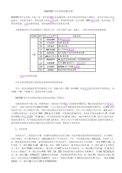
DAX700汽车音响电路分析DAX700型汽车音响,实际上是一种车载MP3U盘播放器,其外形和内部结构如上图所示。
该汽车音响只有电路部分,没有机芯部分。
整机电路主要由电源电路、系统控制电路、显示电路、MP3解码电路、收音电路、音质处理电路、功放电路等组成,其组成框图和信号流程见中图。
该机配置的芯片及在路编号与功能见下表,它们分装在主板.面板上。
主板与面板用连接器相连。
一、电源及其控制电路汽车音响电源电路主要由稳压电路和控制电路组成。
其中,稳压电路通常采用多级稳压方式,将输入的十12V(或+24V)直流电压稳压成各种不同的电压,如+12V、+5v、+3.3V等,提供给各单元电路。
DAX700型汽车音响的电源及其控制电路如下图所示。
电源电路有两个输入端,即整机输入/输出接口的V CC主电源端和ACC端。
VCc端直接接在汽车蓄电池正极上,该端子始终加有+12V(或+24V,下文王要针对采用12V蓄电池供电的机器)的电源电压,而ACC端则是接在汽车上电子钥匙开关的,此端子的电源电压受该开关的控制。
当车上电子钥匙开关打开时,ACC端加上了+12V电源电压,此电压经R45、ZD4稳压为5.6V,为D触发器U4供电。
若此时不按动电源开关Kl,则U4的⑩脚输出低电平(()V),使Q6截止.P沟道的场效应管Q7随之截止,vcc电源电压经Dl、L2后只能向功放集成块Ul供电,而不能通过场效应管Q7( Q7截止,相当于电子开关断开)向稳压块U2输入端提供电源电压,最终使得各级稳压电路均无输出电压送到各单元电路,整机处于等待状态。
1.开机原理待机状态下,按电源开关Kl,将U4的⑩脚电压拉低为0v,但此时触发器仍保持原来的状态,并不翻转,在松手瞬间,开关Kl弹起复位,u4(11)脚突然上升为高电平,产生一个控制脉冲输入U4(11)脚,在脉冲上升沿,触发器的状态发生翻转,Q端⑩脚由低电平变为高电平。
其输出的高电平分为两路:一路经R39使Q6、Q 7导通;另一路经R62使Qll、Q8导通。
车载CD电路讲解
1
17
谢 谢!
1
18
在碟片旋转的同时,进给机构带动激光头做径向运动,在 伺服电路的控制下,才能保证激光束始终照射在盘片的信号轨 迹上。
1
4
四、电路系统原理 1.伺服电路分为聚焦伺服、循迹伺服、进给伺服、主轴伺服。
1)聚焦伺服:使激光头与光盘上信息纹迹之间的距离保持恒定,基本电
路如图:
上下 移动
物镜
激光头
聚焦误差 信号检出
放大器,最大功率4×25W,采用主电源14.4V供电。位于音频 信号末级放大,推动喇叭发出声音。
5、面板控制及显示驱动电路:主要功能是通过操作矩阵
电路对CPU输入指令,通过显示驱动电路处理成串行数据供给 CPU作为输入的操作指令,同时也接收由CPU送回的串行数据, 通过前板驱动IC LC75884W形成驱动信号来驱动显示屏。
6、CPU中央处理器:采用IC SM8060控制整机工作状态,
实现电子调谐,快速接收电台信号,控制面板功能键操作和 LCD显示状态等。
1
9淅沥沥,如牛毛,如花针,如春 姑娘那 柔柔的 发丝…… 雨雾弥 漫,雨 珠
儿串成一个大珠帘,如烟如云地笼罩 了一切 。下面 是美文 阅读网 小编给 大家带 来
1
14
收音及电子音量控制电路原理分析
45、46、47、48脚为音频输出脚,经过IC处理后的音频信号由此输出 至后级功放电路。
50、51脚为时钟振荡脚,主要为IC提供所需的振荡信号。 54、55、57、58脚为外部音频输入脚,如CD的音频输入、AUX的音频 输入等。
1
15
4.中央处理器电路原理图
1
3.收音电路:本产品主要采用软件方式在工厂模式下自动进
行相关参数调整,即可达到最佳性能指标。本产品使用了型号 为TEF6902H的IC,该IC在作为音频处理的同时,也作为收音 FM/AM信号的接收、处理及放大,并解调出立体声信号。
新型BTL功放集成电路TA8220H

新型BTL功放集成电路TA8220H
肖江
【期刊名称】《家庭电子(维修版)》
【年(卷),期】2001(000)012
【摘要】TA8220H是东芝公司最新开发的低电压、单电源供电的双声道BTL功
放集成电路,在8Ω负载下,可以提供2×10W的输出功率,而供电电压仅为13.2V,适合用作汽车音响的大功率输出级。
TA8220H内部框图如图1所示。
该集成电路内设两组独立的前级放大器和BTL输出级,并设有待机控制端和前级电路退耦滤波器。
具有超温和负载短路保护功能。
TA8220H散热片允许接末级地,十分方便散热器安装。
【总页数】1页(P36)
【作者】肖江
【作者单位】无
【正文语种】中文
【中图分类】TN722.75
【相关文献】
1.BTL功放的喇叭保护电路 [J], 成辞
2.BTL功放的喇叭保护电路 [J], 成辞
3.新型BTL功放集成电路TA8220H [J], 肖江
4.清逸伦/G&WTW–368T型胆前石后BTL合并式功功放 [J],
5.新型BTL伴音功放TDA7056A [J], 张玉香
因版权原因,仅展示原文概要,查看原文内容请购买。
推荐-DAX7汽车音响电路分析 精品
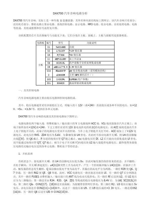
DAX700汽车音响电路分析DAX700型汽车音响,实际上是一种车载U盘播放器,其外形和内部结构如上图所示。
该汽车音响只有部分,没有机芯部分。
整机电路主要由电路、系统控制电路、显示电路、MP3电路、收音电路、音质处理电路、电路等组成,其组成框图和信号流程见中图。
该机配置的芯片及在路编号与功能见下表,它们分装在主板.面板上。
主板与面板用连接器相连。
一、及其控制电路汽车音响电源电路主要由稳压电路和控制电路组成。
其中,稳压电路通常采用多级稳压方式,将输入的十12V(或+24V)直流稳压成各种不同的电压,如+12 V、+5v、+3.3V等,提供给各单元电路。
DAX700型汽车音响的电源及其控制电路如下图所示。
电源电路有两个输入端,即整机输入/输出接口的V主电源端和ACC端。
VCc端直接接在汽车正极上,该端子始终加有+12V(或+24V,下文王要针对采用12V蓄电池供电的机器)的电源电压,而ACC端则是接在汽车上电子钥匙开关的,此端子的电源电压受该开关的控制。
当车上电子钥匙开关打开时,ACC端加上了+12V电源电压,此电压经R45、ZD4稳压为5.6V,为D触发器U4供电。
若此时不按动电源开关Kl,则U4的⑩脚输出低(()V),使Q6截止.P沟道的场效应管Q7随之截止,vcc电源电压经Dl、L2后只能向功放集成块Ul供电,而不能通过场效应管Q7( Q7截止,相当于电子开关断开)向稳压块U2输入端提供电源电压,最终使得各级稳压电路均无输出电压送到各单元电路,整机处于等待状态。
1.开机原理待机状态下,按电源开关Kl,将U4的⑩脚电压拉低为0v,但此时触发器仍保持原来的状态,并不翻转,在松手瞬间,开关Kl弹起复位,u4(11)脚突然上升为高电平,产生一个控制脉冲输入U4(11)脚,在脉冲上升沿,触发器的状态发生翻转,Q端⑩脚由低电平变为高电平。
其输出的高电平分为两路:一路经R39使Q6、Q 7导通;另一路经R62使Qll、Q8导通。
东芝 TA8276HQ 功放音效芯片技术资料
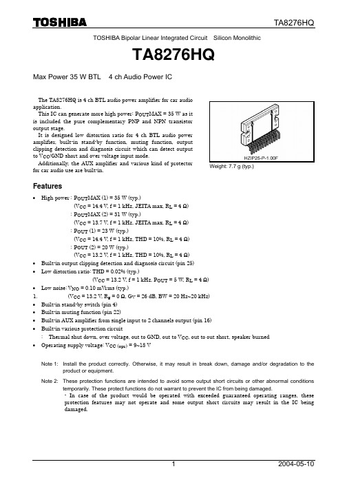
TA8276HQTOSHIBA Bipolar Linear Integrated Circuit Silicon MonolithicTA8276HQMax Power 35 W BTL × 4 ch Audio Power ICThe TA8276HQ is 4 ch BTL audio power amplifier for car audio application. This IC can generate more high power: POUTMAX = 35 W as it is included the pure complementary PNP and NPN transistor output stage. It is designed low distortion ratio for 4 ch BTL audio power amplifier, built-in stand-by function, muting function, output clipping detection and diagnosis circuit which can detect output to VCC/GND short and over voltage input mode. Additionally, the AUX amplifier and various kind of protector for car audio use are built-in.Weight: 7.7 g (typ.)Features• High power : POUTMAX (1) = 35 W (typ.) (VCC = 14.4 V, f = 1 kHz, JEITA max, RL = 4 Ω) : POUTMAX (2) = 31 W (typ.) (VCC = 13.7 V, f = 1 kHz, JEITA max, RL = 4 Ω) : POUT (1) = 23 W (typ.) (VCC = 14.4 V, f = 1 kHz, THD = 10%, RL = 4 Ω) : POUT (2) = 20 W (typ.) (VCC = 13.2 V, f = 1 kHz, THD = 10%, RL = 4 Ω) • • • 1. • • • • • Built-in output clipping detection and diagnosis circuit (pin 25) Low distortion ratio: THD = 0.02% (typ.) (VCC = 13.2 V, f = 1 kHz, POUT = 5 W, RL = 4 Ω) Low noise: VNO = 0.10 mVrms (typ.) (VCC = 13.2 V, Rg = 0 Ω, GV = 26 dB, BW = 20 Hz~20 kHz) Built-in stand-by switch (pin 4) Built-in muting function (pin 22) Built-in AUX amplifier from single input to 2 channels output (pin 16) Built-in various protection circuit : Thermal shut down, over voltage, out to GND, out to VCC, out to out short, speaker burned Operating supply voltage: VCC (opr) = 9~18 VNote 1: Install the product correctly. Otherwise, it may result in break down, damage and/or degradation to the product or equipment. Note 2: These protection functions are intended to avoid some output short circuits or other abnormal conditions temporarily. These protect functions do not warrant to prevent the IC from being damaged. - In case of the product would be operated with exceeded guaranteed operating ranges, these protection features may not operate and some output short circuits may result in the IC being damaged.12004-05-10TA8276HQBlock DiagramC51 TAB20 VCC16 VCC2 OUT1 (+) 9C111IN1 PW-GND1 8 OUT1 (−) 7 RLOUT2 (+) 12 IN25 RLC1PW-GND2 2 OUT2 (−) 3C616AUX INOUT3 (+) 15 IN317 RLC1PW-GND3 18 OUT3 (−) 19OUT4 (+) 14 IN421 RLC1PW-GND4 24 OUT4 (−) 23PRE-GND13 RIP 10 C2CLIP OUT & DIAGNOSIS STBY MUTE OUT 4 25 22 R1 C4: PRE-GND : PW-GNDNote3:Some of the functional blocks, circuits, or constants in the block diagram may be omitted or simplified for explanatory purpose.C322004-05-10TA8276HQCaution and Application Method(Description is made only on the single channel.) 1. Voltage Gain AdjustmentThis IC has no NF (negative feedback) terminals. Therefore, the voltage gain can’t adjusted, but it makes the device a space and total costs saver.Amp. 2A Amp. 1 InputAmp. 2BFigure 1Block DiagramThe voltage gain of Amp.1: GV1 = 0 dB The voltage gain of Amp.2A, B: GV2 = 20 dB The voltage gain of BLT Connection: GV (BTL) = 6 dB Therefore, the total voltage gain is decided by expression below. GV = GV1 + GV2 + GV (BTL) = 0 + 20 + 6 = 26 dB2. Stand-by SW Function (pin 4)By means of controlling pin 4 (stand-by terminal) to high and low, the power supply can be set to ON and OFF. The threshold voltage of pin 4 is set at about 3VBE (typ.), and the power supply current is about 2 µA (typ.) at the stand-by state.VCC ON Power OFF 4 10 kΩ ≈ 2VBE to BIAS CUTTING CIRCUITControl Voltage of pin 4: VSBStand-by ON OFF Power OFF ON VSB (V) 0~1.5 3~VCCFigure 2 With pin 4 set to High, Power is turned ONAdjustage of Stand-by SW(1) (2) Since VCC can directly be controlled to ON or OFF by the microcomputer, the switching relay can be omitted. Since the control current is microscopic, the switching relay of small current capacity is satisfactory for switching32004-05-10TA8276HQLarge current capacity switch BATTERY RELAY BATTERYVCCVCC – Conventional Method –FROM MICROCOMPUTERSmall current capacity switch BATTERYDIRECTLY FROM MICROCOMPUTER BATTERYStand-By VCCStand-By VCC – Stand-by Switch Method –Figure 33. Muting Function (pin 22)By means of controlling pin 22 less than 0.5 V, it can make the audio muting condition. The muting time constant is decided by R1 and C4 and these parts is related the pop noise at power ON/OFF. The series resistance; R1 must be set up less than 10 kΩ to get enough muting attenuation. The muting function have to be controlled by a transistor, FET and µ-COM port which has IMUTE > 250 µA ability. Pin 22 terminal voltage has the temperature characteristics of 4.6 V (low temperature) to 3.2 V (high temperature). Therefore, it is need to design with attention as using the microcontroller of which operating voltage is less than 5 V. Terminal 22 may not be pulled up and shall be controlled by OPEN/LOW. When it is obliged to do, it must be pulled up via diode, because it has to defend flowing reverse current to internal circuit of pin 22.<Recommended Application> ATT – VMUTE20I (100 µA) IMUTE (OFF) 22 C4 R1 IMUTEA(dB)10 kΩ 0 −20 −40 −605 kΩVMUTE<Application for pulled up>Mute attenuation ATTVCC = 13.2 V −80 −100 0 0.4 0.8 1 1.2 1.6 Po = 10 W PL = 4 Ω f = 1 kHz BW = 400~30 kHz 2 2.4 2.8 3I (100 µA) IMUTE (OFF) 22 C4 R1 IMUTE VMUTEPoint A voltage: VMUTE(V)Figure 4Muting FunctionFigure 5 4Mute Attenuation − VMUTE (V) 2004-05-10TA8276HQ4. AUX Input (pin 16)The pin 16 is for input terminal of AUX amplifier. The total gain is 0 dB by using of AUX amplifier. Therefore, the µ-COM can directly drive the AUX amplifier. BEEP sound or voice synthesizer signal can be input to pin 16 directly. When AUX function is not used, this pin must be connected to PRE-GND (pin 13) via a capacitor.20 dB AMP.IN OUT (+)OUT (−) AUX AMP µ-COM AUX-IN 16−20 dBFigure 6 AUX Input5.Diagnosis Output (pin 25)This diagnosis output terminal of pin 25 has open collector output structure on chip as shown in Figure 7. In case diagnosis circuit that detect unusual case is operated, NPN Tr. (Q1) is turned on. It is possible to protect all the system of apparatus as well as power IC protection. In case of being unused this function, use this IC as open-connection on pin 25.5V25 V25 OUTPUT CLIP DETECTOR OUTPUT SHORT PROTECTOR OVER VOLTAGE PROTECTOR GND t Q1 is turned on Q1 5Vpin 25: Open collector output (active low)Figure 75.1Self Diagnosis OutputIn Case of Shorting Output to VCC/GND or Over Voltage Power SuppliedNPN Tr. (Q1) is turned on. Threshold of over voltage protection: VCC = 22 V (typ.)5V µ-COM LED/LCD ALAME (Flashing) (Announcement from a speaker.) OFF (Relay OFF)25REGULATOR MEMORY (Count and record)Figure 85.2Application 1In Case of Shorting Output to OutputNPN Tr. (Q1) is turned on and off in response to the input signal voltage.52004-05-10TA8276HQ5.3 Prevention of speaker burning accident (In Case of Rare Short Circuit of Speaker)When the direct current resistance between OUT + and OUT − terminal becomes 1 Ω or less and output current over 4 A flows, this IC makes a protection circuit operate and suppresses the current into a speaker. This system makes the burning accident of the speaker prevent as below mechanism. <The guess mechanism of a burning accident of the speaker> Abnormal output offset voltage (voltage between OUT + and OUT −) over 4 V is made by the external circuit failure.(Note 4) ↓ The speaker impedance becomes 1 Ω or less as it is in a rare short circuit condition. ↓ The current more than 4 A flows into the speaker and the speaker is burned.Current into a speakerOperating point of protector Less than 4 ΩAbout 1 Ω4ΩSpeaker impedanceFigure 9Note 4: It is appeared by biased input DC voltage (for example, large leakage of the input capacitor, short-circuit between copper patterns of PCB.)5.4ApplicationsWhen output terminals short-circuit to VCC or GND, the voltage of 25pin is fixed to “L”. And when shorting OUT + to OUT −, “L” and “H” are switched according to an input signal. Therefore, it is possible to judge how the power IC condition is if a micro-controller detects the 25pin voltage that is smoothed out with LPF. It is recommend that the threshold voltage (Vth) is set up as higher as possible because output level of LPF is changed according to an input signal. (for example, Vth is set up to 4 V if 25pin is pulled up to 5 V line.)Output voltage of L.P.F. Operating point of protector 5VOutput powerFigure 10 6 2004-05-10TA8276HQ6.Output Clip Detection Function (pin 25)The output clip detection terminal of pin 25 has the open collector output structure on chip as shown in Figure 11. In case that the output waveform is clipping, the clip detection circuit is operated and NPN Tr. is turned on. It is possible to improve the audio quality with controlling the volume, tone control circuit through L.P.F. smoothing circuit as shown in Figure 11. In case of being unused this function, use this IC as open connection on pin 25.(Application) 5V25 OUTPUT CLIP DETECTOR L.P.F. SMOOTHING CIRCUIT VOLUME CONTROL CIRCUIT TONE CONTROL CIRCUITpin 25: Open collector output (active low)Figure 11(A) Output (AC wave form) AC(A)t (B) Clip Detector Circuit (internal)DC(B)t (B) Clip Detector Terminal (pin 25) DC(C) 5VGNDtFigure 12Clip Detection72004-05-10TA8276HQMaximum Ratings (Ta = 25°C)Characteristics Peak supply voltage (0.2 s) DC supply voltage Operation supply voltage Output current (peak) Power dissipation Operation temperature Storage temperature Symbol VCC (surge) VCC (DC) VCC (opr) IO (peak) PD (Note 5) Topr Tstg Rating 50 25 18 9 125 −40~85 −55~150 Unit V V V A W °C °CNote 5: Package thermal resistance θj-T = 1°C/W (typ.) (Ta = 25°C, with infinite heat sink) The absolute maximum ratings of a semiconductor device are a set of specified parameter values, which must not be exceeded during operation, even for an instant. If any of these rating would be exceeded during operation, the device electrical characteristics may be irreparably altered and the reliability and lifetime of the device can no longer be guaranteed. Moreover, these operations with exceeded ratings may cause break down, damage and/or degradation to any other equipment. Applications using the device should be designed such that each maximum rating will never be exceeded in any operating conditions. Before using, creating and/or producing designs, refer to and comply with the precautions and conditions set forth in this documents.Electrical CharacteristicsCharacteristics Quiescent current(unless otherwise specified, VCC = 13.2 V, f = 1 kHz, RL = 4 Ω, Ta = 25°C)Symbol ICCQ POUT MAX (1) Output power POUT MAX (2) POUT (1) POUT (2) Total harmonic distortion Voltage gain Voltage gain ratio Output noise voltage THD GV ∆GV VNO (1) VNO (2) Ripple rejection ratio Cross talk Output offset voltage Input resistance Stand-by current Stand-by control voltage R.R. C.T. VOFFSET RIN ISB VSB H VSB L Mute control voltage (Note 2) VM H VM L Mute attenuation ATT M Test Circuit ⎯ ⎯ ⎯ ⎯ ⎯ ⎯ ⎯ ⎯ ⎯ ⎯ ⎯ ⎯ ⎯ ⎯ ⎯ ⎯ ⎯ ⎯ ⎯ ⎯ VIN = 0 VCC = 14.4 V, max Power VCC = 13.7 V, max Power VCC = 14.4 V, THD = 10% THD = 10% POUT = 5 W VOUT = 0.775 Vrms (0 dBm) VOUT = 0.775 Vrms (0 dBm) Rg = 0 Ω, DIN45405 Rg = 0 Ω, BW = 20 Hz~20 kHz frip = 100 Hz, Rg = 620 Ω Vrip = 0.775 Vrms (0 dBm) Rg = 620 Ω VOUT = 0.775 Vrms (0 dBm) ⎯ ⎯ Stand-by condition Power: ON Power: OFF Mute: OFF Mute: ON, R1 = 10 kΩ Mute: ON, VOUT = 7.75 Vrms (20 dBm) at Mute: OFF. 0 80 Test Condition Min ⎯ ⎯ ⎯ ⎯ 17 ⎯ 24 −1.0 ⎯ ⎯ 40 ⎯ −150 ⎯ ⎯ 3.0 0 Typ. 200 35 31 23 20 0.02 26 0 0.12 0.10 50 65 0 90 2 ⎯ ⎯ Open ⎯ 90 0.5 ⎯ Max 400 ⎯ ⎯ ⎯ ⎯ 0.2 28 dB 1.0 ⎯ 0.35 ⎯ ⎯ 150 ⎯ 10 VCC 1.5 ⎯ V dB mVrms dB dB mV kΩ µA V % W Unit mANote 2: Muting function have to be controlled by open and low logic, which logic is a transistor, FET and µ-COM port of IMUTE > 250 µA ability.This means than the mute control terminal : pin 22 must not be pulled-up.82004-05-10TA8276HQTest Circuit3900 µF1 TAB20 VCC16 VCC2 OUT1 (+) 90.22 µF C1 11IN1 PW-GND1 8 OUT1 (−) 7 RLOUT2 (+) 0.22 µF C1 12 IN25 RLPW-GND2 2 OUT2 (−) 30.22 µF C6 16AUX INOUT3 (+) 0.22 µF C1 15 IN317 RLPW-GND3 18 OUT3 (−) 19OUT4 (+) 0.22 µF C1 14 IN421 RLPW-GND4 24 OUT4 (−) 23PRE-GND13 RIP 10 10 µF C2CLIP OUT & DIAGNOSIS STBY MUTE OUT 4 25 22 10 kΩ R1 1 µF C4: PRE-GND : PW-GNDComponents in the test circuits are only used to obtain and confirm the device characteristics. These components and circuits do not warrant to prevent the application equipment from malfunction or failure.0.1 µFC5C392004-05-10TA8276HQT.H.D – POUT100 VCC = 13.2 V RL = 4 Ω 100 f = 1 kHz RL = 4 ΩT.H.D – POUT(%)10(%) Total harmonic distortion T.H.D10Total harmonic distortion T.H.D1 10 kHz1100 Hz 0.1 1 kHz9.0 V 0.113.2 V16.0 V0.01 0.11101000.01 0.1110100Output powerPOUT(W)Output powerPOUT(W)ICCQ – VCC400 1T.H.D – f(%) Total harmonic distortion T.H.D0.1RL = ∞(mA)VIN = 0 300ICCQOUT3 OUT1 OUT2Quiescent current2000.01 OUT4 VCC = 13.2 V RL = 4 Ω Pout = 5 W 0.001 10 100 1k 10 k 100 k1000 0 10 20 30Power supply voltageVCC (V)Frequency f(Hz)102004-05-10TA8276HQVNO – Rg300 VCC = 13.2 V 0 VCC = 13.2 V −10 −20 −30 −40 −50 −60 −70 10 RL = 4 Ω Rg = 620 Ω Vrip = 0dBmR.R. – f(µVrms)Output noise voltage VNO200150100500 101001k10 kRipple rejection ratioR.R.(dB)RL = 4 Ω 250 BW = 20 Hz~20 kHz100 k1001k10 k100 kSignal source resistance Rg(Ω)Frequency f(Hz)C.T. – f (OUT1)0 VCC = 13.2 V −10 VOUT = 0.775 Vrms (0 dBm) Rg = 620 Ω −10 0 VCC = 13.2 VC.T. – f (OUT2)VOUT = 0.775 Vrms (0 dBm) Rg = 620 Ω RL = 4 ΩCross talk C.T. (dB)−20 −30 −40 −50Cross talk C.T. (dB)OUT1 → OUT2, 3RL = 4 Ω−20 −30 −40 −50 −60−60 −70 10 OUT1 → OUT4 100 1k 10 k 100 kOUT2 → OUT1 OUT2 → OUT3, 4 100 1k 10 k 100 k−70 10Frequency f(Hz)Frequency f(Hz)C.T. – f (OUT3)0 VCC = 13.2 V −10 RL = 4 Ω VOUT = 0dBm Rg = 620 Ω −10 0 VCC = 13.2 V RL = 4 Ω VOUT = 0dBm Rg = 620 ΩC.T. – f (OUT4)Cross talk C.T. (dB)−30 −40 OUT3 → OUT4 −50 OUT3 → OUT1 −60 −70 10 OUT3 → OUT2 100 1k 10 k 100 kCross talk C.T. (dB)−20−20 −30 −40 −50 −60 −70 10OUT4 → OUT3OUT4 → OUT1, 2 100 1k 10 k 100 kFrequency f(Hz)Frequency f(Hz)112004-05-10TA8276HQGV – f40 35 70 60PD – POUTGV (dB)30 25 20 15 10 5 0 10(W)5016 VPower dissipation PD40 13.2 V 30 20 9V 10 0 f = 1 kHz RL = 4 Ω 0 5 10 15 20 25Voltage gainVCC = 13.2 V RL = 4 Ω VOUT = 0.775 Vrms (0 dBm) 100 1k 10 k 100 kFrequency f(Hz)Output powerPOUT/ch (C)PD MAX – Ta120(w)INFINITE HEAT SINK RθJC = 1°C/W 100 HEAT SINK (RθHS = 3.5°C/W) RθJC + RθHS = 4.5°C/W 80 NO HEAT SINK RθJA = 39°C/WAllowable power dissipation PD MAX.6040200 0 25 50 75 100 125 150Ambient temperatureTa (°C)122004-05-10TA8276HQPackage DimensionsWeight: 7.7 g (typ.)132004-05-10TA8276HQAbout solderability, following conditions were confirmed • Solderability (1) Use of Sn-63Pb solder Bath · solder bath temperature = 230°C · dipping time = 5 seconds · the number of times = once · use of R-type flux (2) Use of Sn-3.0Ag-0.5Cu solder Bath · solder bath temperature = 245°C · dipping time = 5 seconds · the number of times = once · use of R-type fluxRESTRICTIONS ON PRODUCT USE• The information contained herein is subject to change without notice.030619EBF• The information contained herein is presented only as a guide for the applications of our products. No responsibility is assumed by TOSHIBA for any infringements of patents or other rights of the third parties which may result from its use. No license is granted by implication or otherwise under any patent or patent rights of TOSHIBA or others. • TOSHIBA is continually working to improve the quality and reliability of its products. Nevertheless, semiconductor devices in general can malfunction or fail due to their inherent electrical sensitivity and vulnerability to physical stress. It is the responsibility of the buyer, when utilizing TOSHIBA products, to comply with the standards of safety in making a safe design for the entire system, and to avoid situations in which a malfunction or failure of such TOSHIBA products could cause loss of human life, bodily injury or damage to property. In developing your designs, please ensure that TOSHIBA products are used within specified operating ranges as set forth in the most recent TOSHIBA products specifications. Also, please keep in mind the precautions and conditions set forth in the “Handling Guide for Semiconductor Devices,” or “TOSHIBA Semiconductor Reliability Handbook” etc.. • The TOSHIBA products listed in this document are intended for usage in general electronics applications (computer, personal equipment, office equipment, measuring equipment, industrial robotics, domestic appliances, etc.). These TOSHIBA products are neither intended nor warranted for usage in equipment that requires extraordinarily high quality and/or reliability or a malfunction or failure of which may cause loss of human life or bodily injury (“Unintended Usage”). Unintended Usage include atomic energy control instruments, airplane or spaceship instruments, transportation instruments, traffic signal instruments, combustion control instruments, medical instruments, all types of safety devices, etc.. Unintended Usage of TOSHIBA products listed in this document shall be made at the customer’s own risk. • The products described in this document are subject to the foreign exchange and foreign trade laws. • TOSHIBA products should not be embedded to the downstream products which are prohibited to be produced and sold, under any law and regulations. • This product generates heat during normal operation. However, substandard performance or malfunction may cause the product and its peripherals to reach abnormally high temperatures. The product is often the final stage (the external output stage) of a circuit. Substandard performance or malfunction of the destination device to which the circuit supplies output may cause damage to the circuit or to the product.142004-05-10。
常用功放IC大全

397 TDA7240AH 20WBRIDGE AMPLIFIER FOR CAR RADIO
STMicroelectronics
396 TDA7240AV 20WBRIDGE AMPLIFIER FOR CAR RADIO
33 TDA8925ST Power stage 2 x 15 to 25Wclass-D audio amplifier
32 TDA8926 Power stage 2 x 50 W class-D audio amplifier
31 TDA8926J Power stage 2 x 50 W class-D audio amplifier
10.前置放大集成电路 前置放大集成电路属于低噪声、低失真、高增益、宽频带的运算放大器,有较高的输入阻抗和良好的线性.
常用的前置放大集成电路有NE5532、NE5534、NE5535、OP248、TL074、TL082、TL084、LM324、LM381、LM382、LM833、LM837等型号.
秀涛电子 更多资料请查看官方网站
TDA8920 2 x 50 W class-D power amplifier
NXP Semiconductors
48 TDA8920B 2 X 100 W class-D power amplifier
17 TDA8941P 1.5 W mono Bridge Tied Load BTL audio amplifier
16 TDA8942 2 x 1.5 W stereo Bridge Tied Load BTL audio amplifier
音频放大器电路图

音频放大器电路图:
这是音频功率放大器的典型应用电路,它受设计的限制,无法在高电路噪音环境中工作。
提高旁路电容值便可改善电源抑制比。
但旁路电容值高,开启时间可能会延长,且电容体积增大,这样做并不切实际。
图二:
这是设有“渐强渐弱”功能的音频功率放大器应用电路。
它添加“渐强渐弱”功能,当LM4897放大器获得停机管脚的供电并重新启动之后,输出电平会慢慢上升。
每当收到停机信号之后,输出电平便会逐渐下降至零,启动/关闭时间可以通过输入电阻及电容器加以设定。
图三:
这是采用无需旁路电容的音频放大器。
没有旁路电容器,启动时间便可缩短,而且仍可在217Hz与1kHz的噪音下分别维持高达62dB与66dB的电源抑制比。
该音频放大器内置输入及反馈电阻,工程师可以利用外接的控制逻辑管脚选择2倍(6dB)或4倍(12dB)的可编程增益,外接元件数目可大幅减少至两颗。
TDA7850-V8版(含BA3121)车载HIFI四声道功放模块产品规格书
二、剑飞电子车载四声道系列产品一览表
序 版本号
号
发行
前级隔 前级放 电位
颜色 PCB 尺寸
目前状态
年份
离模块 大模块 器
1 TDA7850-V1 2005 白色
/
否
2 TDA7850-V2 2007 蓝色
/
否
3 TDA7850-V3 2008 红色 78*48mm 否
再谈汽车音响升级,含功放升级(带电子分频器的CDT4声道放大器)!
duar发表于 2009-11-28 04:12:53| 只看该作者查看 2268 / 回复 5楼主再谈汽车音响升级,含功放升级(带电子分频器的CDT4声道放大器)!本帖最后由 duar 于 2009-12-14 11:57:07 修改先前写过一篇《宝来车音响系统升级手工图解》帖子,因为掉了些图片,现在把它补齐,算是个交代。
一、先说音响升级,也就是扬声器升级。
1、机头升级:原厂配给的机头已经进入梦乡。
喇叭功率太小,所以机头不在改造升级讨论之列。
因为技术更新太快。
个人喜好各异。
现在好的机头带高清屏,像数仍是普通的,等出了1980X1200再换也不迟。
2、扬声器系统:N年了扬声器的性能和结构、材料提升很慢,基本上一次升级到位,终身都可不换,只怕车子寿命还没有扬声器系统寿命长。
注意扬声器的磁钢材料、气孔、直径、厚度、纸盆材质、音圈是否为耐高温、大口径这些后,市面上品种非常丰富,简单的说通过重量和参数比较是能够选到很理想的产品。
原车配备的扬声器都不是很好,按照个头估算额定功率不会超过10W,那些所谓专业店改装的喇叭一样是垃圾,成本不过15元,不要被洋文字给骗了。
他们会毫不留情的放大20倍价格告诉你,有名气的扬声器厂家就那么几家。
在外面改装的整套系统不过是垃圾一堆。
3、音箱:这个只能说尽量利用车门、储藏箱等空间,一般说只要箱体空间大于扬声器锥体有效推动空气体积的25倍以上均有较好的效果,低频不得小于80倍。
市售的汽车里面音响放大器由于采用12V供电,功率都不是很大,4声道也不过65WX4 4Ω。
BTL估计100W。
现在直接改用专用音频喇叭阻抗大多在8Ω,低音更是如此。
本次升级如下:高音单元,采用带式高音,A柱使用长方形带式高音30W/8Ω,后门上的高音采用圆形带式高音。
这个高音在将军电器城有售,约120元一对。
拆卸:原高音拆除,联线注意相位即可。
中音单元:6.5寸,气孔厚磁钢长冲程250W 8Ω(约75元一只)。
BTL功放电路

BTL功放电路集成功率放大器由于不仅具有体积小、重量轻、成本低、外围元件少、安装调试简单、使用方便的优点;而且在性能上也优于分立元件,例如温度稳定性好,功耗小、失真小,特别是集成功率放大器内部还设置有过热、过电流、过电压等自动保护功能的电路对电路自行进行保护。
由于集成功率放大器具有分立元件不具有的很多优点,近年来集成功率放大器件发展很快,使用相当广泛。
产品有单通道和双通道、单功放、双功放及多功放等器件。
集成功放在实际应用中通常接成OCL电路,或OTL电路,接成BTL(Balanced Transformer Less)电路却很少,而BTL电路的优点是电源利用率比前面两种电路高4倍。
本文从BTL电路的结构、原理出发,分析BTL电路输入、输出信号特点,最后介绍如何用集成功率放大器件构成BTL 电路。
1BTL电路1.1BTL电路的组成及工作原理大家知道OCL和OTL两种功放电路的效率很高,但是他们的缺点就是电源的利用率都不高,其主要原因是在输入正弦信号时,在每半个信号周期中,电路只有一个晶体管和一个电源在工作。
为了提高电源的利用率,也就是在较低电源电压的作用下,使负载获得较大的输出功率,一般采用平衡式无输出变压器电路,又称为BTL电路。
电路如图1所示。
在输入信号U i正半周时,V1,V4导通,V2,V3截止,负载电流由V CC经V1,R L,V4流到虚地端。
如图1中的实线所示。
在输入信号Ui负半周时,V1,V4载止,V2,V3导通,负载电流由V CC经V2,R L,V3流到虚地端。
如图1中虚线所示。
可见:(1)该电路仍然为乙类推挽放大电路,利用对称互补的2个电路完成对输入信号的放大;其输出电压的幅值为:U OMV CC最大输出功率为:(2)同OTL电路相比,同样是单电源供电,在V CC,R L相同条件下,BTL电路输出功率为OTL电路输出功率的4倍,即BTL电路电源利用率高;(3)BTL电路的效率在理想情况下,仍近似为78.5%。
集成音频功放IC应用于BTL方法探讨与实验
集成音频功放IC 应用于BTL 方法探讨与实验陈永飞B TL(Bridge-Tied-load)意为桥接式负载。
负载的两端分别接在两个放大器的输出端。
其中一个放大器的输出是另外一个放大器的镜像输出,也就是说加在负载两端的信号仅在相位上相差180°。
负载上将得到原来单端输出的2倍电压。
从理论上来讲电路的输出功率将增加4倍。
BTL 电路能充分利用系统电压,因此BTL 结构常应用于低电压系统或电池供电系统中。
在汽车音响中当每声道功率超过10w 时,大多采用BTL 形式。
BTL形式不同于推挽形式,BTL 的每一个放大器放大的信号都是完整的信号,只是两个放大器的输出信号反相而已。
用集成功放块构成一个BTL 放大器需要一个双声道或两个单声道的功放块。
但是并不是所有的功放块都适用于BTL 形式,BTL 形式的几种接法也各有优劣、下面藉助于制作实验,对各种接法逐一介绍。
实验中用到的功放集成块有LM1875,LM3886,TDA1514,LM4766。
由于个人比较偏好于LM4766的音色,且其他IC 的应用杂志上也多有介绍。
因此以LM4766的BTL 应用为例。
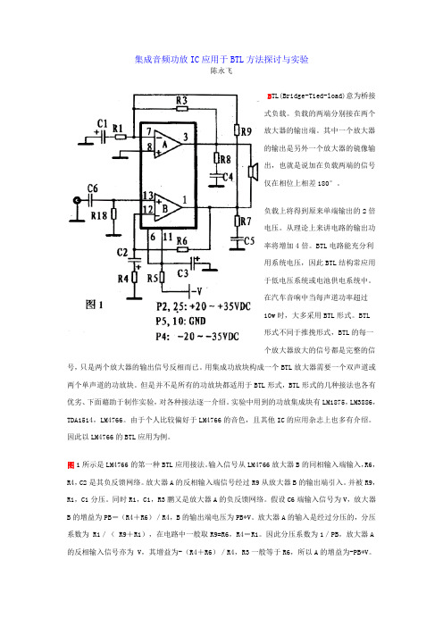
图1所示是LM4766的第一种BTL 应用接法。
输入信号从LM4766放大器B 的同相输入端输入,R6,R4,C2是其负反馈网络。
放大器A 的反相输入端信号经过R9从放大器B 的输出端引入。
并被R9,R1,C1分压。
同时R1,C1,R3鹏又是放大器A 的负反馈网络。
假设C6端输入信号为V ,放大器B 的增益为PB =(R4+R6)/R4,B 的输出端电压为PB*V 。
放大器A 的输入是经过分压的,分压系数为 R1/( R9+R1),在电路中一般取R9=R6,R4=R1。
因此分压系数为1/PB ,放大器A 的反相输入信号亦为 V ,其增益为-(R4+R6)/R4,R3一般等于R6,所以A 的增益为-PB*V。
在负载上得到的输出为此两信号的迭加,即2PB*V。
