S555-5999-40中文资料
TI LMC555 CMOS计时器说明书

ProductFolderOrderNowTechnicalDocumentsTools &SoftwareSupport &CommunityLMC555ZHCSI70M–FEBRUARY2000–REVISED JULY2016 LMC555CMOS计时器1特性•业界超快的非稳态频率(3MHz)•采用业界超小型8凸点DSBGA封装(1.43mm×1.41mm)•采用5V电源时的典型功耗小于1mW• 1.5V电源工作电压保证•采用5V电源的情况下输出与TTL和CMOS逻辑完全兼容•针对10mA和50mA输出电流电平进行了测试•降低了输出转换期间的电源电流尖峰•极低的复位、触发和阈值电流•出色的温度稳定性•与555系列计时器之间实现了引脚对引脚兼容2应用•精准计时•脉冲发生•顺序计时•时延生成•脉宽调制•脉冲位置调制•线性斜坡发生器3说明LMC555器件是业界标准555系列通用计时器的CMOS版本。
除了标准封装(SOIC、VSSSOP和PDIP)外,LMC555还有采用TI DSBGA封装技术的芯片尺寸封装(8凸点DSBGA封装)。
LMC555具有与LM555相同的产生精确时延和频率的能力,但功耗和电源电流尖峰要低得多。
在一次性模式下,时延由单个外部电阻器和电容器精确控制。
在非稳态模式下,振荡频率和占空比由两个外部电阻器和一个电容器精确设置。
TI LMCMOS工艺的运用扩展了频率范围和低电源能力。
器件信息(1)器件型号封装封装尺寸(标称值)LMC555SOIC(8) 4.90mm×3.91mmVSSOP(8) 3.00mm×3.00mmPDIP(8)9.81mm×6.35mmDSBGA(8) 1.43mm×1.41mm (1)如需了解所有可用封装,请参阅数据表末尾的可订购产品附录。
脉宽调制器脉宽调制器波形:上面的波形-调制下面的波形-输出电压LMC555ZHCSI70M–FEBRUARY2000–REVISED 目录1特性 (1)2应用 (1)3说明 (1)4修订历史记录 (2)5引脚配置和功能 (3)6规格 (4)6.1绝对最大额定值 (4)6.2ESD额定值 (4)6.3建议运行条件 (4)6.4热性能信息 (4)6.5电气特性 (5)7参数测量信息 (6)8详细说明 (7)8.1概述 (7)8.2功能框图 (7)8.3特性说明 (7)8.4器件功能模式.............................................................89以下一些应用中 (11)9.1应用信息 (11)9.2典型应用 (11)9.3分频器 (13)9.4脉宽调制器 (13)9.5脉冲位置调制器 (14)9.650%占空比振荡器 (15)10电源建议 (16)11布局 (16)11.1布局指南 (16)11.2布局示例 (16)12器件和文档支持 (17)12.1接收文档更新通知 (17)12.2社区资源 (17)12.3商标 (17)12.4静电放电警告 (17)12.5术语表 (17)13机械、封装和可订购信息 (17)4修订历史记录Changes from Revision L(February2016)to Revision M Page•已更改特性列表的顺序。
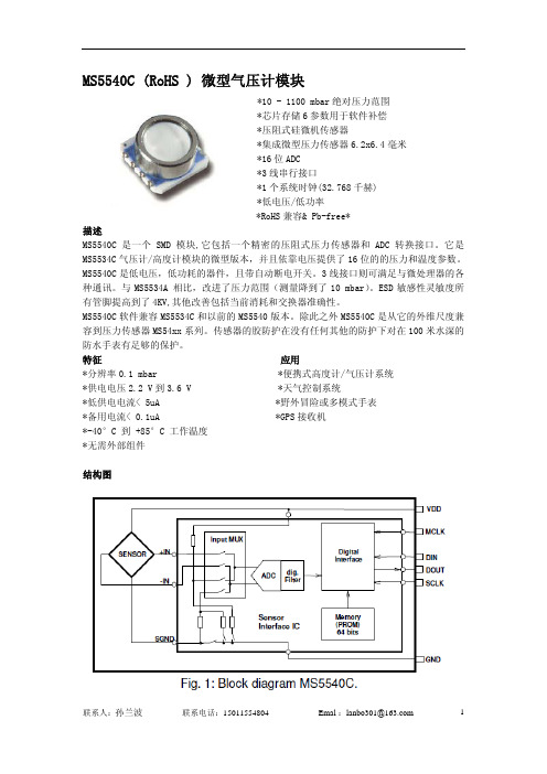
MS5540C中文版
压力和温度测量
压力和温度读数次序和软件补偿操作在图3,图5的流程图里有描述。 首先通过串行接口读取1段字节到4段字节。重起连接MS5540C串行接口的微控制器后可以立 即完成1段字节到4段字节的读取。 其次补偿系数C1到C6通过逻辑和转移操作逐位提取(参见 图4). 为压力测量微控制器在闭路环内(例如每秒钟)必须通过串行接口为压力(D1)和温度(D2) 读 16个位值。然后,根据图3的运算法则,补偿的压力在D1、D2和C1至C6外面被计算(根据图5, 可能使用二次方温度补偿).增殖的结果也许是由32位长决定(+sign)。 在流程中根据图3每 次增殖伴随一次分裂。 这次分裂可以通过逐位转移执行(到功率2是除数)。可以保证的是这 些分裂的结果少于65536(16位)。 由于信号定时由1段字节到4段字节,D1和 D2读出,请参见“串行接口”章节
联系人:孙兰波
联系电话:15011554804
Emal :lanbo301@
9
Fig. 3:压力/温度读取和软件补偿流程图
注意
1)可以不连续地读取D2,但在这种情况下结果将是较为不稳定的。 2)为0.1mbar分辨率显示的稳定性,建议显示8其后的压力平均值。
联系人:孙兰波
联系电话:15011554804
*-40°C 到 +85°C 工作温度
*无需外部组件
结构图
联系人:孙兰波
联系电话:15011554804
Emal :lanbo301@
SES5VT553-5 中文资料
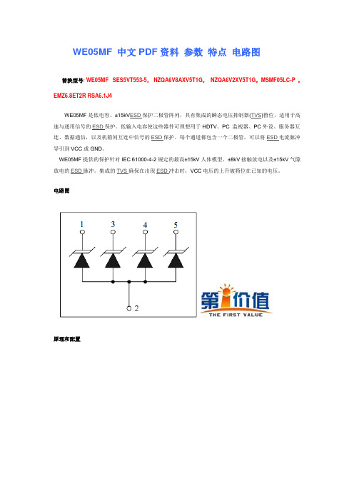
WE05MF 中文PDF资料参数特点电路图
替换型号:WE05MF SES5VT553-5, NZQA6V8AXV5T1G,NZQA6V2XV5T1G,MSMF05LC-P ,EMZ6.8ET2R RSA6.1J4
WE05MF是低电容、±15kV ESD保护二极管阵列,具有集成的瞬态电压抑制器(TVS)箝位,适用于高速与通用信号的ESD保护。
低输入电容使这些器件可理想用于HDTV、PC 监视器、PC外设、服务器互连、数据通信,以及机箱间互连中信号的ESD保护。
每个通道都包含一个二极管,可以将ESD电流脉冲导引到VCC或GND。
WE05MF提供的保护针对IEC 61000-4-2规定的最高±15kV人体模型、±8kV接触放电以及±15kV气隙放电的ESD脉冲。
集成的TVS确保在出现ESD冲击时,VCC电压的上升被箝位在已知的电压。
电路图
原理和配置
电参数
电性能参数
外形图-SOT-553:
尺寸规格
DIM 英寸外型尺寸
Z 0.0708 1.80
G 0.0354 0.90
P 0.0197 TYP 0.50 TYP
X 0.0118 0.3
来源: 第一价值网(IC网络超市)。
555芯片
555芯片引脚图555 定时器是一种模拟和数字功能相结合的中规模集成器件。
一般用双极性工艺制作的称为555,用CM OS 工艺制作的称为7555,除单定时器外,还有对应的双定时器556/7556。
555 定时器的电源电压范围宽,可在 4.5V~16V 工作,7555 可在3~18V 工作,输出驱动电流约为200mA,因而其输出可与TTL、CMOS 或者模拟电路电平兼容。
555 定时器成本低,性能可靠,只需要外接几个电阻、电容,就可以实现多谐振荡器、单稳态触发器及施密特触发器等脉冲产生与变换电路。
它也常作为定时器广泛应用于仪器仪表、家用电器、电子测量及自动控制等方面。
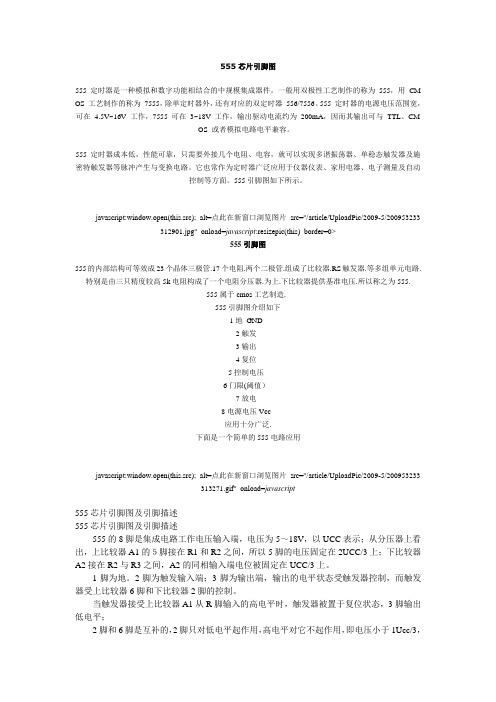
555引脚图如下所示。
javascript:window.open(this.src); alt=点此在新窗口浏览图片src="/article/UploadPic/2009-5/200953233312901.jpg" onload=javascript:resizepic(this) border=0>555引脚图555的内部结构可等效成23个晶体三极管.17个电阻.两个二极管.组成了比较器.RS触发器.等多组单元电路.特别是由三只精度较高5k电阻构成了一个电阻分压器.为上.下比较器提供基准电压.所以称之为555.555属于cmos工艺制造.555引脚图介绍如下1地GND2触发3输出4复位5控制电压6门限(阈值)7放电8电源电压Vcc应用十分广泛.下面是一个简单的555电路应用javascript:window.open(this.src); alt=点此在新窗口浏览图片src="/article/UploadPic/2009-5/200953233313271.gif" onload=javascript555芯片引脚图及引脚描述555芯片引脚图及引脚描述555的8脚是集成电路工作电压输入端,电压为5~18V,以UCC表示;从分压器上看出,上比较器A1的5脚接在R1和R2之间,所以5脚的电压固定在2UCC/3上;下比较器A2接在R2与R3之间,A2的同相输入端电位被固定在UCC/3上。
S555中文资料
Document Number: 63007For any questions, contact: foil@Military and Space Established ReliabilityVishay Foil ResistorsBulk Metal ® Foil TechnologyRNC90Y and RNC90Z (Z-Foil) to MIL-PRF-55182/9INTRODUCTIONVishay Military Established Reliability resistors are available in resistance values from 4.99 Ω through 121 k Ω and for tolerances from ± 0.005 % to ± 1.0 %. The same resistors are also available as a non-qualified product for customers desiring higher or lower resistance values and the same or better performance capabilities. (See table 2) Both the qualified and the non-qualified version are manufactured on the same production line facilities and are subjected to the same process, lot control, conditioning, and GRP A (100 %)screening. Qualified versions receive additional MIL Group B and C testing.FEATURES•QPL product with established reliability (R): meets requirements of MIL-PRF-55182/9•Load life stability: ± 0.005 % for 2000 h, 0.3 W at + 125 °C •Temperature coefficient of resistance (TCR): ± 2 ppm/°C max.(- 55 °C to + 175 °C)•Resistance tolerance: to ± 0.005 %•Thermal EMF: < 0.1 µV/°C•Qualified resistance range: 4.99 Ω to 121 k Ω (RNC90Y)30.1 Ω to 121 k Ω (RNC90Z)•Specially conditioned non-QPL resistors available See data sheet “Improved Performance Tested”•Fast thermal stabilization•Rise time: 1 ns without ringing•Special coatings that provide a cushioning layer which isolates the resistive element from external stresses and moisture •Electrostatic discharge (ESD) above 25 000 V •Non inductive, non capacitive design •Current noise < - 42 dB•Prototype sample available from 72 hNotes1.Qualification and failure rate verification test data is maintained by Vishay Foil and is available upon request. Lot traceability and identification data is maintained by Vishay Foil for 7 years.2.Load life ΔR Maximum can be reduced by 80 % through Enhanced Reliability Testing (ERT). Consult Vishay Applications Engineering for details.3.Inductance (L) due mainly to the leads.4.Not to exceed power rating of resistor.5.µV/°C relates to EMF due to lead temperature differences and µV/W due to power applied to the resistor.6.0.200" (5.08 mm) lead spacing available - specify RNC90T for RNC90Y, and RNC90S for RNC90Z.TABLE 1 - SPECIFICATIONS COMPARISONSPECIFICATION RNC90Y (QUALIFIED) MIL-PRF-55182/9 CHARACTERISTIC Y LIMITS RNC90Z (QUALIFIED) MIL-PRF-55182/9 CHARACTERISTIC Z LIMITS S555 (NON-QUALIFIED)VISHAY PERFORMANCE LIMITS Z555 (NON-QUALIFIED)VISHAY PERFORMANCE LIMITSTemperature Coefficient of Resistance ± 5 ppm/°C ± 2 ppm/°C ± 5 ppm/°C± 3 ppm/°C ± 2.5 ppm/°C ± 2 ppm/°C(- 55 °C to + 125 °C)(- 55 °C to + 175 °C)(- 55 °C to + 125 °C)± 10 ppm/°C(- 55 °C to + 125 °C)(+ 125 °C to + 175 °C)Resistance Range 4.99 Ω to 121 k Ω30.1 Ω to 121 k Ω 1 Ω to 150 k Ω 4.99 Ω to 25 Ω> 25 Ω to 80 Ω> 80 ΩFailure RateLevel R Level R Not specified Not specifiedLoad-Life Stability 0.3 W at + 125 °C at 2000 h ± 0.05 % maximum ΔR ± 0.05 % maximum ΔR ± 0.015 % maximum ΔR 2)± 0.015 % maximum ΔR 2)at 10000 h ± 0.5 % maximum ΔR± 0.5 % maximum ΔR± 0.05 % maximum ΔR 2)± 0.05 % maximum ΔR 2)Current Noise Not specified Not specified - 40 dB minimum - 40 dB minimumHigh-Frequency Operation Rise TimeNot specified Not specified 1.0 ns at 1 k Ω 1.0 ns at 1 k ΩInductance 3) (L)Not specified Not specified 0.1 µH maximum 0.1 µH maximum 0.08 µH typical 0.08 µH typical Capacitance (C)Not specified Not specified 1.0 pF maximum 1.0 pF maximum 0.5 pF typical 0.5 pF typical Voltage Coefficient 0.0005 %/V 0.0005 %/V 0.0001 %/V 0.0001 %/V Working Voltage 4)300 V maximum 300 V maximum 300 V maximum 300 V maximum Thermal EMF 5)Not specifiedNot specified0.1 µV/°C maximum 0.1 µV/°C maximum 1 µV/W maximum 1 µV/W maximumMilitary and Space Established ReliabilityVishay Foil ResistorsBulk Metal ® Foil TechnologyRNC90Y and RNC90Z (Z-Foil) to MIL-PRF-55182/9 For any questions, contact: foil@Document Number: 63007Document Number: 63007For any questions, contact: foil@Military and Space Established ReliabilityBulk Metal ® Foil Technology RNC90Y and RNC90Z (Z-Foil) to MIL-PRF-55182/9Vishay Foil ResistorsNote•S555 and Z555 units are manufactured on the same production line facilities and are subjected to all the same process and lot control requirements imposed on RNC90Y (Z) version, as well as all of the special screening, environmental conditioning and documentation stipulations outlined in MIL-PRF 55182/9Note* For non-standard requests, please contact application engineering.TABLE 2 - MODEL SELECTIONMODELNUMBER RESISTANCE RANGE (Ω)STANDARD RESISTANCETOLERANCE FAILURE RATE AMBIENT POWER RATING AVERAGE WEIGHT(g)DIMENSIONS TIGHTEST %LOOSEST %at + 70 °C at + 125 ° C INCHES mmRNC90Y30.1 to 121K ± 0.005± 1.0M, P , R (SeeT able 3)0.6 W 0.3 W 0.6W: 0.105 ± 0.010L: 0.300 ± 0.010H: 0.326 ± 0.010ST: 0.015 ± 0.005SW: 0.040 ± 0.005LL: 1.000 ± 0.125LS: 0.150 ± 0.005 2.67 ± 0.257.62 ± 0.258.28 ± 0.250.38 ± 0.131.02 ± 0.1325.4 ± 3.183.81 ± 0.1316.2 to 30.0± 0.05± 1.04.99 to 16.0± 0.1± 1.0RNC90Z 30.1 to 121K ± 0.005± 1.00.6 W 0.3 W 0.6S555(NON QPL)30.1 to 121K ± 0.005± 1.0-0.6 W 0.3 W 0.620 to < 30.1± 0.01± 1.05 to < 20± 0.05± 1.02 to < 5± 0.1± 1.01 to < 2± 0.5± 1.0> 121K to 150K ± 0.005± 1.0-0.4 W 0.2 W 0.6Z555(NON QPL)30.1 to 121K ± 0.005± 1.0-0.6 W 0.3 W 0.620 to < 30.1± 0.01± 1.04.99 to < 20R ± 0.05± 1.0TABLE 3 - GLOBAL PART NUMBER INFORMATIONNEW GLOBAL PART NUMBER:Y1189100R500AR0L (preferred part number format)DENOTES PRECISIONVALUE LIFE FAILURE RATE (LFR)AER*YR = ΩK = k ΩR = ± 0.01 %P = ± 0.1 %M = ± 1.0 %0 = standard 1 - 999 = customPRODUCT CODE RESIST ANCE TOLERANCEPACKAGING 1189 = RNC90Z 0089 = RNC90Y 1508 = RNC90T 1506 = RNC90S 0088 = S5551288 = Z555V = ± 0.005 %T = ± 0.01 %A = ± 0.05 %B = ± 0.1 %D = ± 0.5 %F = ± 1.0 %L = bulk pack R = tape and reelFOR EXAMPLE: ABOVE GLOBAL ORDER Y1189 100R500 A R 0 L:TYPE: RNC90Z VALUE: 100.5 ΩABSOLUTE TOLERANCE: ± 0.05 %LIFE FAILURE RATE (LFR): ± 0.01 %AER: standardPACKAGING: bulk packHISTORICAL PART NUMBER:RNC90Z 100R50A R B (will continue to be used)RNC90Z 100R50A R B MODEL OHMIC VALUERESIST ANCE TOLERANCE LIFE FAILURE RA TE (LFR)P ACKAGING RNC90Z RNC90S RNC90Y RNC90T S555Z555100.5 ΩV = ± 0.005 %T = ± 0.01 %A = ± 0.05 %B = ± 0.1 %D = ± 0.5 %F = ± 1.0 %R = ± 0.01 %P = ± 0.1 %M = ± 1.0 %B = bulk pack18910R 50Y 1A R 000LMilitary and Space Established ReliabilityVishay Foil ResistorsBulk Metal ® Foil TechnologyRNC90Y and RNC90Z (Z-Foil) to MIL-PRF-55182/9 For any questions, contact: foil@Document Number: 63007The response of military and non military grade resistors to environmental stresses can be made better by “Improved Performance Testing” (IPT). The IPT part will see burn-in and cycling that removes the “knee” from the normal drift of non IPT parts. (See Table 4 for the improvement to expect in military parts when calling for Vishay recommended screening). Users should be aware that IPT testing renders the part non QPL and so a 3XXXXX part number will be assigned by Vishay. Consult Applications Engineering for details and ordering advice.CAGE #18612“Commercial and Government Entity”Formerly “FSCM”TABLE 4 - IMPROVED PERFORMANCE TESTING (NON-QPL APPROVED) VS. QPLTEST GROUPTESTRNC90YMIL-PRF-55182/9VISHAYIMPROVED PERFORMANCETESTING (IPT) LIMITS METHOD PARAGRAPHLIMITS IPower Conditioning not done -± 0.0025 %Thermal Shock and 4.8.2-± 0.0025 %Overload Combined 4.8.3± 0.05 %± 0.0025 %IIResistance TemperatureCharacteristic 4.8.9± 5 ppm/°C< ± 2 ppm/°C (- 55 °C to + 125 °C)(Can be sorted for tighter tracking)Low T emperature Storage 4.8.23± 0.05 %± 0.0025 %Low Temperature Operation4.8.10± 0.05 %± 0.0025 %T erminal Strength4.8.11± 0.02 %± 0.001 %IIIDWV4.8.12± 0.02 %± 0.001 %Insulation Resistance 4.8.13104 M Ω> 104 M ΩResistance to Soldering Heat4.8.14± 0.02 %± 0.001 %Moisture Resistance4.8.15± 0.05 %± 0.015 %IV Shock 4.8.16± 0.01 %± 0.0025 %Vibration4.8.17± 0.02 %± 0.0025 %V Load Life at + 125 °C; 2000 h 4.8.18± 0.05 %± 0.005 % (50 ppm)Load Life at + 125 °C; 10000 h4.8.18± 0.5 %± 0.015 % (150 ppm)V (a)+ 85 °C Power Rating --± 0.005 % (50 ppm)+ 70 °C Power Rating 4.8.18± 0.05 %± 0.005 % (50 ppm)V (b)+ 25 °C Power Rating--± 0.005 % (50 ppm)VI Storage Life--± 0.0025 %VII High T emperature Exposure 4.8.19± 0.5 %± 0.005 %VIIIMax. Allowance Reactance--< 1 %Current Noise --< - 42 dB Voltage Coefficient4.8.200.0005 %/V < 0.00001 %/V -(5 ppm/V)(< 0.1 ppm/V)Thermal EMF--0.1 µV/°CDisclaimer Legal Disclaimer NoticeVishayAll product specifications and data are subject to change without notice.Vishay Intertechnology, Inc., its affiliates, agents, and employees, and all persons acting on its or their behalf (collectively, “Vishay”), disclaim any and all liability for any errors, inaccuracies or incompleteness contained herein or in any other disclosure relating to any product.Vishay disclaims any and all liability arising out of the use or application of any product described herein or of any information provided herein to the maximum extent permitted by law. The product specifications do not expand or otherwise modify Vishay’s terms and conditions of purchase, including but not limited to the warranty expressed therein, which apply to these products.No license, express or implied, by estoppel or otherwise, to any intellectual property rights is granted by this document or by any conduct of Vishay.The products shown herein are not designed for use in medical, life-saving, or life-sustaining applications unless otherwise expressly indicated. Customers using or selling Vishay products not expressly indicated for use in such applications do so entirely at their own risk and agree to fully indemnify Vishay for any damages arising or resulting from such use or sale. Please contact authorized Vishay personnel to obtain written terms and conditions regarding products designed for such applications.Product names and markings noted herein may be trademarks of their respective owners.元器件交易网Document Number: 。
sa555用法

sa555用法全文共四篇示例,供读者参考第一篇示例:SA555是一种常用的集成电路,通常用作定时器和脉冲发生器。
它是一个精密的计时器,具有多种应用。
SA555的使用非常广泛,可以在各种电子设备和电路中找到它的身影。
在本文中,我们将介绍SA555的用法以及一些常见的应用场景。
让我们了解一下SA555的基本结构和原理。
SA555是一种双电源、稳态或脉冲调制定时器,由著名的电子公司意法半导体(STMicroelectronics)生产。
它是555定时器的改进版本,具有更高的稳定性和可靠性。
SA555内部集成了比555更多的功能模块,可以实现更多不同的应用。
SA555的引脚布局与555基本一致,通常来说,一共有8个引脚。
引脚1是电源输入引脚VCC,引脚2是阴极输出引脚OUT,引脚3是复位引脚RESET,引脚4是控制电平引脚CTRL,引脚5是电压比较器的控制电平引脚THR,引脚6是电压比较器的控制电平引脚TRIG,引脚7是放大器的反馈引脚DISCH,引脚8是电源输入引脚GND。
SA555的工作原理主要是通过内部比较器、放大器和电流源实现的。
具体来说,当输入电压VCTRL超过VTHR时,输出引脚OUT输出高电平。
当输入电压VTRIG低于1/3的电源电压时,输出引脚OUT输出低电平。
当输入电压VTRIG高于2/3的电源电压时,输出引脚OUT输出高电平。
根据这些原理,我们可以设计各种不同的定时器和脉冲发生器电路。
SA555可以实现多种不同的功能,可以用作脉冲发生器、频率测量仪、闪光灯控制器等。
下面我们将介绍一些常见的应用场景。
SA555可以用作简单的脉冲发生器。
通过调整引脚CTRL的电压,可以控制脉冲的频率和占空比。
通过外部电阻和电容的组合,可以调整脉冲的周期和占空比。
脉冲发生器可以用于各种电子设备和测量仪器中,例如数字电路和信号发生器。
SA555还可以用作定时器。
通过设置外部电阻和电容的数值,可以实现不同的时间延迟效果。
负向阈值电压为V气敏传感器采用QM
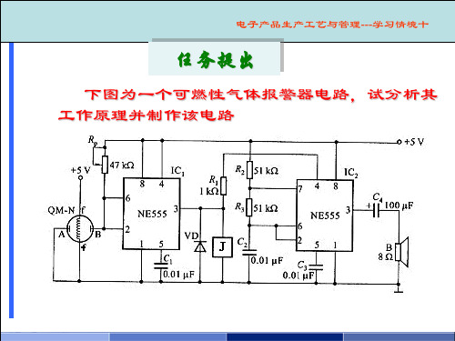
任务提出
下图为一个可燃性气体报警器电路,试分析其 工作原理并制作该电路
电子产品生产工艺与管理---学习情境十
任务目标
通过对可燃性气体报警器电路的分析与制作, 理解和掌握集成555定时器的工作原理及其应用方 法 ,能按工艺要求独立进行电路装配、测试和调 试,并能独立排除装配、调试过程中出现的简单 故障。
(2)555定时器典型应用
构成施密特触发器
电子产品生产工艺与管理---学习情境十
构成单稳态触发器
电子产品生产工艺与管理---学习情境十
构成多谐振荡器
电子产品生产工艺与管理---学习情境十
f 1
1
T 0.7(R1 2R2 )C
电子产品生产工艺与管理---学习情境十
占空比可调的矩形脉冲发生器
输出信号的形式有电流输出和电压输出。对电流输出的 DAC,常常需外接运放将电流转换成电压。左图为反相电压输
出,uOUT=-iRf;右图是同相电压输出, uOUT=-iR3(1+ R2/R1)。
电子产品生产工艺与管理---学习情境十
集成D/A转换芯片
DAC0830系列是8位分辨率的集成D/A转换电路,采用 20脚双列直插封装。主要特性参数如下:
将输入的每一位二进制代码按其权的大小转换成相应 的模拟量,然后将代表各位的模拟量相加,所得的总模拟 量就与数字量成正比,这样便实现了从数字量到模拟量的 转换。
N位 二进
d0 d1
制代
码
dn-1
…
DAC
模拟
uO或iO 输出
uo Ku (dn1 2n1 dn2 2n2 d1 21 d0 20 )
q R1 100 % R1 R2
sa555用法

sa555用法全文共四篇示例,供读者参考第一篇示例:SA555是一种经典的IC集成电路,可以应用于各种定时器、脉冲信号发生器和振荡器等功能。
它常用于电子电路设计中,具有精度高、可靠性强等优点,被广泛应用于电子产品中。
SA555的基本原理是通过内置的双稳态触发器来产生一个稳定的方波输出信号。
它由比较器、RS触发器和输出级组成,可以根据外部元件如电阻、电容的取值来调整输出信号的频率和占空比。
SA555的引脚功能如下:1. GND:地端2. TRIG:触发端,用于接收外部触发信号3. OUT:输出端,输出方波信号4. RESET:复位端,可以通过外部信号对SA555进行复位5. CTRL VCC:控制电压端,连接至电源正极6. THRS:阈值端,与TRIG共同作用于RS触发器7. DISCH:放电端,用于控制电容的放电过程8. VCC:电源端SA555的使用方法:1. 确定工作电压范围SA555的工作电压范围通常为4.5V-16V,因此需要根据实际需求选择适当的电源电压。
2. 接线连接将SA555的引脚按照需求连接至其他元件,保证电路连接正确。
3. 设置电阻和电容数值通过调节接在TRIG和THRS引脚上的电阻和电容的数值,可以调整SA555输出信号的频率和占空比。
4. 外部触发信号通过外部信号(如按钮、传感器等)给TRIG引脚提供触发信号,从而触发SA555产生输出信号。
5. 测试与调试在连接电路后,需要通过示波器或多用表等工具来检测SA555输出信号的波形,并根据需要调整电阻和电容的数值。
SA555常用于各种电子电路设计中,如LED闪烁灯、蜂鸣器、计时器、脉冲信号发生器等。
在实际应用中,需要根据具体需求选择合适的元件和参数,保证电路工作正常稳定。
SA555具有功能强大、性能稳定等优点,适用于各种电子电路设计中,是电子工程师常用的集成电路之一。
希望通过本文的介绍,读者对SA555的用法有所了解,能够在实际应用中灵活运用。
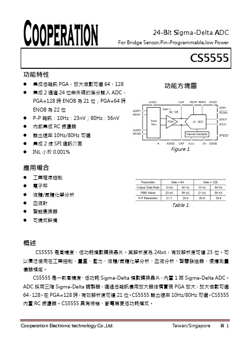
CS5555-中文规格书
時鐘為4.9152MHz 全建立
PGA=128,DR=10Hz PGA=128
10
80
Hz
4
轉換週期
145
nv
±2
±3
ppm
失調誤差 失調誤差漂移
增益誤差
PGA=128 PGA=128 PGA=128
-1 25 ±0.1
uV nv/℃
%
增益誤差漂移 參考電壓輸入
負參考電壓輸入 正參考電壓輸入
PGA=128
PGA 放大器輸出,CAP1、CAP2 之間外接 0.1~0.44uF 電容
通道 1 正輸入 通道 1 負輸入 通道 2 負輸入 通道 2 正輸入 參考電壓負端輸入 參考電壓正端輸入 模擬地 模擬電源 PGA 選擇:0:選擇 PGA64;1:選擇 PGA128 輸出速率選擇:speed=0,10Hz;speed=1,80Hz power down 控制埠(低電平有效) SPI 時鐘輸入埠 SPI 資料登錄/輸出埠
Table 2.
參數
條件
最小值
典型值
最大值
單位
模擬輸入 滿幅輸入電壓(AINP-AIN)
共模輸入電壓 共模電壓抑制比
PGA=64,128
±0.5VREF/PGA
V
AGND+1.5
AVDD-1.5
V
125
dB
差分輸入阻抗 系統性能
解析度
PGA=64、128 無失碼
>1
GΩ
24
Bits
AD速率 建立時間 P-P雜訊 積分線性度
功能方塊圖
Figure 1.
應用場合
工業程序控制 電子秤 液體/氣體化學分析 血液計 智能變換器 可擕式設備
555s_精品文档
555sIntroduction:The 555s is a popular integrated circuit (IC) timer that has been widely used in various applications. It was first introduced in 1971 by Signetics (now a part of NXP Semiconductors) and remains in production today. The 555s IC is versatile and can function as a timer, oscillator, and pulse-width modulator (PWM) with its three internal functional blocks: a voltage divider, a comparator, and a flip-flop.Functionality:The primary function of the 555s IC is as a timer. It can generate precise and adjustable time delays, ranging from microseconds to hours. This timer function makes it a valuable component in many electronic devices, including industrial control systems, lighting systems, and consumer electronics.The 555s IC operates in three different modes, namely monostable, astable, and bistable modes.1. Monostable Mode:In monostable mode, the 555s functions as a one-shot pulse generator. When triggered by an external signal, the IC produces an output pulse of a fixed duration. This mode is commonly used in applications such as timers, delay circuits, and electronic switches.2. Astable Mode:In astable mode, the 555s operates as a free-running oscillator, generating continuous square wave pulses. The frequency and duty cycle of the output pulses can be adjusted by selecting appropriate values for the external timing components connected to the IC. Astable mode finds applications in areas like frequency generators, LED flashers, and tone generators.3. Bistable Mode:Bistable mode, also known as flip-flop mode, enables the 555s to function as a basic memory element. In this mode, the IC remains in one of two stable states until triggered by an external signal. Bistable mode is used in applications like flip-flop circuits, binary counters, and frequency dividers.Features:The 555s IC offers several features that contribute to its widespread use and popularity:1. Wide operating voltage range:The IC can operate within a wide voltage range, typically from 4.5V to 16V. This flexibility makes it suitable for use in both low power and high-power applications.2. Adjustable timing range:By selecting appropriate timing components, the 555s IC can generate time delays ranging from microseconds to hours. This versatility enables its application in a broad range of timing-related projects.3. High output current capability:The IC can source or sink up to 200 mA of current, allowing it to directly drive small loads such as LEDs, relays, and low-power motors.4. Ease of use:The 555s IC has a simple and intuitive pinout, with only eight pins. This simplicity eases the circuit design process andcontributes to its widespread use among both hobbyists and professionals.Applications:The 555s IC finds applications in various fields due to its versatility and ease of use. Some of its common applications are:1. Timing circuits:The timer function of the 555s IC makes it suitable for applications requiring precise time delays, such as traffic light controllers, cooking timers, and battery chargers.2. Oscillators:The astable mode of the 555s IC allows it to generate square wave signals of adjustable frequencies. This feature proves useful in applications like clock generators, frequency synthesizers, and tone generators.3. Motor speed control:By using the 555s as a PWM generator, it is possible to control the speed of DC motors. This feature is utilized inapplications such as electric fans, robotic systems, and motorized vehicles.4. Security systems:The 555s IC can be used in combination with sensors and switches to create simple security systems. For example, it can trigger an alarm or turn on lights when motion is detected or a door is opened.Conclusion:The 555s IC has undoubtedly earned its place as one of the most popular and versatile integrated circuits in the electronics industry. Its ability to function as a timer, oscillator, and pulse-width modulator, along with its ease of use and wide range of applications, has made it a staple component for both hobbyists and professionals alike. As technology continues to advance, the 555s IC remains a reliable and indispensable tool for electronic designers.。
奈姆 555PS 用户手册 - 电源说明书

用户手册电源中文版E1 1 连接E1 2 主电源E2 3 一般安装E3 4 CD555PS,超容量和XPSE4 5 大容量,小容量XS,NAPSA和NAPSC E5 6 电源规格E5 7 符合性声明11 连接随机提供的标准导线未被修改对安全和性能是非常重要的。
1.1如果您的设备和安装可以进行不同选择,DIN 互连插座应优先于RCA 唱机插座使用。
Naim 互连导线的一端带有确定其正确方向的彩带。
该彩带标记连接到信号源的一端。
互联插头和插座应保持清洁,免受腐蚀。
清洁它们的最简单方法是关掉设备,从插座拔出插头,并再次将其放回。
不应使用接触清洁剂和“增强剂”,因为其集聚形成的膜会降低音效。
1.2音箱导线的作用非常重要。
导线至少应3.5米长,且每根长度相等。
建议一般情况下最大长度为20米,但部分Naim 扩音器可能采用更长的导线。
部分Naim 扩音器只能与Naim 扬声器导线共同使用,使用替代品可能会降低扩音器性能,甚至破坏扩音器。
虽然我们建议使用Naim 扬声器导线,但部分Naim 扩音器可以与任何高品质的音箱线共同使用。
Naim 扬声器导线具有方向性,应该使印刷的箭头指向扬声器。
随机提供的Naim 扬声器连接器的设计符合欧洲安全法,必须使用此连接器进行连接。
请联系当地零售商或分销商获取关于扬声器导线和连接器的更多信息。
2 主电源凡使用融合插头时,应配置13安培保险丝。
较低额定值保险丝会在使用一段时间后失去作用。
不要将压敏电阻器或噪声抑制器与主电源插头连接。
它们会降低主电源和声音效果。
Naim 音频产品将性能作为首要考虑因素。
小心安装将有助于确保实现其全部功能。
本手册涵盖了所有电源供应设备。
它从一般性的安装说明和法定的安全警告开始进行阐述。
关于产品的具体信息从第4节开始阐述。
2.1 在部分地区,电源插头可能需要与随机提供的电源线连接。
由于电源导线中电线的颜色可能与标识插头端子的彩色标记不一致,具体如下:绿黄相间的电线必须连接到由字母E 或安全接地符号或绿色或黄绿色标记的插头终端。
5R55N-_5R55S-_5R55W

011H 5R55N (Plastic) (0.4” Pickup Tube)........................................................................... 1 99-Up 46011 011H 5R55S (Metal/Plastic) (1.3” Pickup Tube) (Car)......................................................... 1 03-Up 46011B 011H 5R55S/W (Metal/Plastic) (2.4” Pickup Tube) (SUV).................................................... 1 02-Up 46011A
H
46
195
FORD 5R55N, 5R55S, 5R55W
46300W
46010
46010A 46010B
5R55N (99-Up)
Lincoln LS Jaguar X200
5R55W/S (02-Up)
Explorer
ill.
DESCRIPTION
QTY. YEAR
PART NO.
DELUXE KITS (SUPER KITS)
5R55N
5R55N
FORD 5R55N, 5R55S, 5R55W
F
G
Deluxe Kit---------------------------------- 008 Compliance Kit------------------------- 007 Master Kit -------------------------------- 006 Less Steel Kit--------------------------- 004 Overhaul Kit ----------------------------- 002 Bushing Kit ------------------------------- 030 Washer Kit -------------------------------- 200 Bearing Kit ------------------------------- 201 Technical Manual ------------------ 400 Pump Part---------------------------------- 507 Valve Body Parts -------------------- 741 Case Parts ------------------------------- 761 Note: Not all items are available for all transmissions
SA555

tr tf toff
Notes :
5. No protection against excessive Pin 7 current is necessary, providing the package dissipation rating will not be exceeded. 6. Time mesaured from a positive going input pulse from 0 to 0.8x VCC into the threshold to the drop from high to low of the output trigger is tied to treshold.
®
NE555 SA555 - SE555
GENERAL PURPOSE SINGLE BIPOLAR TIMERS
. . . . . . . .
LOW TURN OFF TIME MAXIMUM OPERATING FREQUENCY GREATER THAN 500kHz TIMING FROM MICROSECONDS TO HOURS OPERATES IN BOTH ASTABLE AND MONOSTABLE MODES HIGH OUTPUT CURRENT CAN SOURCE OR SINK 200mA ADJUSTABLE DUTY CYCLE TTL COMPATIBLE TEMPERATURE STABILITY OF 0.005% PERoC
RES ET DISCHARGE
4 7 Q14
Q15 Q17 R5 10kΩ R6 100kΩ R7 100kΩ
R10 5kΩ
G ND
1
TRIGGER COMPARATOR
SE556中文资料

元器件交易网IMPORTANT NOTICETexas Instruments and its subsidiaries (TI) reserve the right to make changes to their products or to discontinueany product or service without notice, and advise customers to obtain the latest version of relevant informationto verify, before placing orders, that information being relied on is current and complete. All products are soldsubject to the terms and conditions of sale supplied at the time of order acknowledgement, including thosepertaining to warranty, patent infringement, and limitation of liability.TI warrants performance of its semiconductor products to the specifications applicable at the time of sale inaccordance with TI’s standard warranty. Testing and other quality control techniques are utilized to the extentTI deems necessary to support this warranty. Specific testing of all parameters of each device is not necessarilyperformed, except those mandated by government requirements.CERTAIN APPLICATIONS USING SEMICONDUCTOR PRODUCTS MAY INVOLVE POTENTIAL RISKS OFDEATH, PERSONAL INJURY, OR SEVERE PROPERTY OR ENVIRONMENTAL DAMAGE (“CRITICALAPPLICATIONS”). TI SEMICONDUCTOR PRODUCTS ARE NOT DESIGNED, AUTHORIZED, ORWARRANTED TO BE SUITABLE FOR USE IN LIFE-SUPPORT DEVICES OR SYSTEMS OR OTHERCRITICAL APPLICATIONS. INCLUSION OF TI PRODUCTS IN SUCH APPLICATIONS IS UNDERSTOOD TOBE FULLY AT THE CUSTOMER’S RISK.In order to minimize risks associated with the customer’s applications, adequate design and operatingsafeguards must be provided by the customer to minimize inherent or procedural hazards.TI assumes no liability for applications assistance or customer product design. TI does not warrant or representthat any license, either express or implied, is granted under any patent right, copyright, mask work right, or otherintellectual property right of TI covering or relating to any combination, machine, or process in which suchsemiconductor products or services might be or are used. TI’s publication of information regarding any thirdparty’s products or services does not constitute TI’s approval, warranty or endorsement thereof.Copyright © 1999, Texas Instruments Incorporated。
S558-5999-P3中文资料
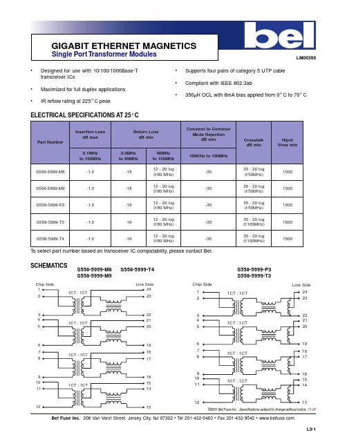
Single Port Transformer Modules
MECHANICALS
0.070 [1.78] ref 0.020 [0.51] 0.050 [1.27] 0.480 [12.19] 0.645 [16.38] 0.030 [0.76] 0.070 [1.78] R0.045 [R1.14] Suggested PCB Pad Layout R0.015 [R0.38]
L3-2
-30
1500
S558-5999-M9
-1.0
-18
-30
1500
S558-5999-P3
-1.0
-18
-30
1500
S558-5999-T3
-1.0
-18
-30
1500
S558-5999-T4
-1.0
-18
-30
1500
To select part number based on transceiver IC compatability, please contact Bel.
Crosstalk dB min
Hipot Vrms min
100KHz to 100MHz 33 - 20 log (f/50MHz) 33 - 20 log (f/50MHz) 33 - 20 log (f/50MHz) 33 - 20 log (f/100MHz) 33 - 20 log (f/100MHz)
©2001 Bel Fuse Inc. Specifications subject to change withoel Fuse Inc. 206 Van Vorst Street Jersey City, NJ 07302 Tel 201-432-0463 Fax 201-432-9542
硅芯片拆解:早期 555 定时器芯片内部一览
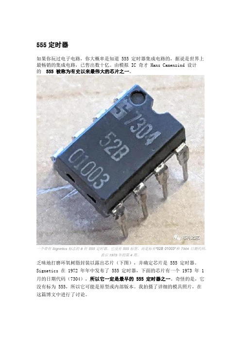
555定时器如果你玩过电子电路,你大概率是知道 555 定时器集成电路的,据说是世界上最畅销的集成电路,已售出数十亿。
由模拟 IC 奇才 Hans Camenzind 设计的555 被称为有史以来最伟大的芯片之一。
一个带有 Signetics 标志的 8 针 555 定时器。
它没有 555 标签,而是标有“52B 01003”和 7304 日期代码,表示 1973 年的第 4 周。
乏味地打磨环氧树脂封装以露出芯片(下图),并确定芯片是 555 定时器。
Signetics 在 1972 年年中发布了 555 定时器,下面的芯片有一个 1973 年 1 月的日期代码(7304),所以它一定是最早的 555 定时器之一。
奇怪的是,它没有标为 555,所以它可能是原型或内部版本。
我拍摄了详细的模具照片,在这篇博文中进行了讨论。
555 定时器的封装被打磨,露出硅芯片,中间的小方块。
简要说明555 定时器有数百种应用,从定时器或锁存器到压控振荡器或调制器的任何操作。
下图说明了 555 定时器如何作为一个简单的振荡器工作。
在 555 芯片内部,三个电阻形成一个分压器,产生 1/3 和 2/3 的电源电压的参考电压。
外部电容器将在这些限制之间充电和放电,从而产生振荡。
更详细地说,电容器将通过外部电阻器缓慢充电 (A),直到其电压达到 2/3 参考电压。
在该点 (B),上(阈值)比较器关闭触发器并关闭输出。
这会打开放电晶体管,使电容器 (C) 缓慢放电。
当电容器上的电压达到 1/3 参考电压 (D) 时,较低(触发)比较器打开,设置触发器和输出,循环重复。
电阻器和电容器的值控制时间,从微秒到几小时。
显示 555 定时器如何作为振荡器工作的图表。
在 555 定时器的控制下,外部电容器通过外部电阻器进行充电和放电。
总而言之,555 定时器的关键组件是检测电压上限和下限的比较器、设置这些限制的三电阻分压器以及跟踪电路是充电还是放电的触发器。
ST NE555 SA555 SE555 说明书

现货库存、技术资料、百科信息、热点资讯,精彩尽在鼎好!March 2007 Rev 41/20NE555SA555 - SE555General purpose single bipolar timersFeatures■Low turn off time■Maximum operating frequency greater than 500kHz■Timing from microseconds to hours ■Operates in both astable and monostable modes■High output current can source or sink 200mA ■Adjustable duty cycle ■TTL compatible■Temperature stability of 0.005% per °CDescriptionThe NE555 monolithic timing circuit is a highly stable controller capable of producing accurate time delays or oscillation. In the time delay mode of operation, the time is precisely controlled by one external resistor and capacitor. For a stable operation as an oscillator, the free runningfrequency and the duty cycle are both accurately controlled with two external resistors and one capacitor.The circuit may be triggered and reset on falling waveforms, and the output structure can source or sink up to 200mA.Contents NE555 - SA555 - SE555Contents1Schematic diagrams . . . . . . . . . . . . . . . . . . . . . . . . . . . . . . . . . . . . . . . . . 3 2Absolute maximum ratings and operating conditions . . . . . . . . . . . . . 4 3Electrical characteristics . . . . . . . . . . . . . . . . . . . . . . . . . . . . . . . . . . . . . 54Application information . . . . . . . . . . . . . . . . . . . . . . . . . . . . . . . . . . . . . . 94.1Monostable operation . . . . . . . . . . . . . . . . . . . . . . . . . . . . . . . . . . . . . . . . . 94.2Astable operation . . . . . . . . . . . . . . . . . . . . . . . . . . . . . . . . . . . . . . . . . . . 104.3Pulse width modulator . . . . . . . . . . . . . . . . . . . . . . . . . . . . . . . . . . . . . . . 134.4Linear ramp . . . . . . . . . . . . . . . . . . . . . . . . . . . . . . . . . . . . . . . . . . . . . . . 134.550% duty cycle oscillator . . . . . . . . . . . . . . . . . . . . . . . . . . . . . . . . . . . . . 144.6Additional information . . . . . . . . . . . . . . . . . . . . . . . . . . . . . . . . . . . . . . . . 15 5Package information . . . . . . . . . . . . . . . . . . . . . . . . . . . . . . . . . . . . . . . . 16 6Ordering information . . . . . . . . . . . . . . . . . . . . . . . . . . . . . . . . . . . . . . . 19 7Revision history . . . . . . . . . . . . . . . . . . . . . . . . . . . . . . . . . . . . . . . . . . . 192/20NE555 - SA555 - SE555Schematic diagrams3/201 Schematic diagramsAbsolute maximum ratings and operating conditions NE555 - SA555 - SE5554/202 Absolute maximum ratings and operating conditionsTable 1.Absolute maximum ratingsSymbol ParameterValue Unit V CC Supply voltage 18V T j Junction temperature 150°C T stgStorage temperature range-65 to 150°CTable 2.Operating conditionsSymbolParameterValue UnitV CCSupply voltage NE555SA555SE5554.5 to 164.5 to 164.5 to 18VV th , V trig , V cl , V reset Maximum input voltageV CC VT operOperating free air temperature range NE555SA555SE5550 to 70-40 to 105-55 to 125°CNE555 - SA555 - SE555Electrical characteristics5/203 Electrical characteristicsTable 3.T amb = +25°C, V CC = +5V to +15V (unless otherwise specified)SymbolParameterSE555NE555 - SA555UnitMin.Typ.Max.Min.Typ.Max.I CCSupply current (R L = ∝)Low stage V CC = +5VV CC = +15VHigh state V CC = 5V 31025123102615mATiming error (monostable)(R A = 2k to 100k Ω, C = 0.1μF)Initial accuracy (1)Drift with temperature Drift with supply voltage0.5300.0521000.21500.130.5%ppm/°C %/VTiming error (astable)(R A, R B = 1k Ω to 100k Ω, C = 0.1μF , V CC = +15V)Initial accuracy -(1)Drift with temperature Drift with supply voltage1.5900.152.251500.3%ppm/°C %/V V CLControl voltage level V CC = +15V V CC = +5V 9.62.9103.3310.43.892.6103.33114VV th Threshold voltage V CC = +15V V CC = +5V 9.42.7103.3310.648.82.4103.3311.24.2V I th Threshold current (2)0.10.250.10.25µA V trig Trigger voltage V CC = +15V V CC = +5V4.81.4551.67 5.21.9 4.51.151.67 5.62.2V I trig Trigger current (V trig = 0V)0.50.90.5 2.0µA V reset Reset voltage (3)0.40.710.40.71V I resetReset current V reset = +0.4V V reset = 0V0.10.40.410.10.40.41.5mAV OLLow level output voltageV CC = +15V I O(sink) = 10mAI O(sink) = 50mA I O(sink) = 100mA I O(sink) = 200mAV CC = +5V I O(sink) = 8mAI O(sink) = 5mA 0.10.422.50.10.050.150.52.20.250.20.10.422.50.30.250.250.752.50.40.35VV OHHigh level output voltageV CC = +15V I O(sink) = 200mAI O(sink) = 100mAV CC = +5V I O(sink) = 100mA13312.513.33.312.752.7512.513.33.3VElectrical characteristics NE555 - SA555 - SE5556/20I dis(off)Discharge pin leakage current (output high) V dis = 10V 2010020100nAV dis(sat)Discharge pin saturation voltage (output low) (4)V CC = +15V , I dis = 15mA V CC = +5V , I dis = 4.5mA 1808048020018080480200mVt r t f Output rise time Output fall time100100200200100100300300ns t offTurn off time (5) (V reset = V CC )0.50.5µs1.Tested at V CC = +5V and V CC = +15V.2.This will determine the maximum value of R A + R B for 15V operation. The maximum total (R A + R B ) is 20M Ω for 15Voperation and 3.5M Ω for +5V operation.3.Specified with trigger input high.4.No protection against excessive pin 7 current is necessary, providing the package dissipation rating is not exceeded.5.Time measured from a positive pulse (from 0V to 0.8xV CC ) on the Threshold pin to the transition from high to low on theOutput pin. Trigger is tied to Threshold.Table 3.T amb = +25°C, V CC = +5V to +15V (unless otherwise specified)SymbolParameterSE555NE555 - SA555UnitMin.Typ.Max.Min.Typ.Max.NE555 - SA555 - SE555Electrical characteristics7/20Figure 3.Minimum pulse width required forFigure 4.Supply current versus supply Figure 5.Delay time versus temperature Figure 6.Low output voltage versus outputFigure 7.Low output voltage versus output sink currentFigure 8.Low output voltage versus output sink currentElectrical characteristicsNE555 - SA555 - SE5558/20Figure 9.High output voltage drop versusFigure 10.Delay time versus supply voltageFigure 11.Propagation delay versus voltageNE555 - SA555 - SE555Application information9/204 Application information4.1 Monostable operationIn the monostable mode, the timer generates a single pulse. As shown in Figure 12, theexternal capacitor is initially held discharged by a transistor inside the timer.The circuit triggers on a negative-going input signal when the level reaches 1/3 V CC . Once triggered, the circuit remains in this state until the set time has elapsed, even if it is triggered again during this interval. The duration of the output HIGH state is given by t = 1.1 R 1C 1 and is easily determined by Figure 14.Note that because the charge rate and the threshold level of the comparator are bothdirectly proportional to supply voltage, the timing interval is independent of supply. Applying a negative pulse simultaneously to the reset terminal (pin 4) and the trigger terminal (pin 2) during the timing cycle discharges the external capacitor and causes the cycle to start over. The timing cycle now starts on the positive edge of the reset pulse. During the time the reset pulse is applied, the output is driven to its LOW state.When a negative trigger pulse is applied to pin 2, the flip-flop is set, releasing the short-circuit across the external capacitor and driving the output HIGH. The voltage across the capacitor increases exponentially with the time constant t = R 1C 1. When the voltage across the capacitor equals 2/3 V CC , the comparator resets the flip-flop which then discharges the capacitor rapidly and drives the output to its LOW state.Figure 13 shows the actual waveforms generated in this mode of operation.When Reset is not used, it should be tied high to avoid any possibility of unwanted triggering.Application information NE555 - SA555 - SE55510/204.2 AstableoperationWhen the circuit is connected as shown in Figure15 (pin 2 and 6 connected) it triggers itselfand free runs as a multi-vibrator. The external capacitor charges through R1 and R2 anddischarges through R2 only. Thus the duty cycle can be set accurately by adjusting the ratioof these two resistors.In the astable mode of operation, C1 charges and discharges between 1/3 V CC and 2/3 V CC.As in the triggered mode, the charge and discharge times and, therefore, frequency areindependent of the supply voltage.NE555 - SA555 - SE555Application information11/20Figure 16 shows the actual waveforms generated in this mode of operation.The charge time (output HIGH) is given by:t1 = 0.693 (R 1 + R 2) C 1and the discharge time (output LOW) by:t2 = 0.693 (R 2) C 1Thus the total period T is given by:T = t1 + t2 = 0.693 (R1 + 2R2) C1The frequency of oscillation is then:It can easily be found from Figure 17.The duty cycle is given by:f = 1T --- 1.44R12R2+()C1--------------------------------------=D R2R12R2+-------------------------=Application information NE555 - SA555 - SE55512/20NE555 - SA555 - SE555Application information13/204.3 Pulse width modulatorWhen the timer is connected in the monostable mode and triggered with a continuous pulse train, the output pulse width can be modulated by a signal applied to pin 5. Figure 18 shows the circuit.4.4 Linear rampWhen the pull-up resistor, R A , in the monostable circuit is replaced by a constant currentsource, a linear ramp is generated. Figure 19 shows a circuit configuration that will perform this function.Application informationNE555 - SA555 - SE55514/20Figure 20 shows the waveforms generator by the linear ramp.The time interval is given by:4.5 50% duty cycle oscillatorFor a 50% duty cycle, the resistors R A and R E can be connected as in figure 19. The time period for the output high is the same as for astable operation (see Section 4.2 on page 10):t1 = 0.693 R A C For the output low it isThus the frequency of oscillation is:T = (2/3 Vcc RE (R1+R2) CR1 Vcc - VBE (R1+R2)--------------------------------------------------------------- VBE = 0.6Vt 2[(R. RB)/(RA+RB)].C.Ln RB 2RA–2RB RA–--------------------------=f 1t1t2+----------------=NE555 - SA555 - SE555Application information15/20Note that this circuit will not oscillate if R B is greater than 1/2 R A because the junction of R A and R B cannot bring pin 2 down to 1/3 V CC and trigger the lower comparator.4.6 Additional informationAdequate power supply by passing is necessary to protect associated circuitry. Theminimum recommended is 0.1µF in parallel with 1µF electrolytic.Package information NE555 - SA555 - SE55516/205 Package informationIn order to meet environmental requirements, STMicroelectronics offers these devices inECOPACK ® packages. These packages have a lead-free second level interconnect. The category of second level interconnect is marked on the package and on the inner box label, in compliance with JEDEC Standard JESD97. The maximum ratings related to soldering conditions are also marked on the inner box label. ECOPACK is an STMicroelectronics trademark. ECOPACK specifications are available at: .NE555 - SA555 - SE555Package information17/20Package information NE555 - SA555 - SE55518/20NE555 - SA555 - SE555Ordering information19/206 Ordering information7 Revision historyTable 4.Order codesPart number Temperature rangePackage Packing Marking NE555N 0°C, +70°CDIP8TubeNE555N NE555D/DT SO8T ube or tape & reelNE555SA555N -40°C, +105°CDIP8TubeSA555N SA555D/DT SO8T ube or tape & reelSA555SE555N -55°C, + 125°CDIP8TubeSE555N SE555D/DTSO8T ube or tape & reelSE555Date RevisionChanges1-Jun-20031Initial release.2004-20062-3Internal revisions15-Mar-20074Expanded order code table.Template update.NE555 - SA555 - SE55520/20Please Read Carefully:Information in this document is provided solely in connection with ST products. STMicroelectronics NV and its subsidiaries (“ST”) reserve the right to make changes, corrections, modifications or improvements, to this document, and the products and services described herein at any time, without notice.All ST products are sold pursuant to ST’s terms and conditions of sale.Purchasers are solely responsible for the choice, selection and use of the ST products and services described herein, and ST assumes no liability whatsoever relating to the choice, selection or use of the ST products and services described herein.No license, express or implied, by estoppel or otherwise, to any intellectual property rights is granted under this document. If any part of this document refers to any third party products or services it shall not be deemed a license grant by ST for the use of such third party products or services, or any intellectual property contained therein or considered as a warranty covering the use in any manner whatsoever of such third party products or services or any intellectual property contained therein.UNLESS OTHERWISE SET FORTH IN ST’S TERMS AND CONDITIONS OF SALE ST DISCLAIMS ANY EXPRESS OR IMPLIED WARRANTY WITH RESPECT TO THE USE AND/OR SALE OF ST PRODUCTS INCLUDING WITHOUT LIMITATION IMPLIED WARRANTIES OF MERCHANTABILITY, FITNESS FOR A PARTICULAR PURPOSE (AND THEIR EQUIVALENTS UNDER THE LAWS OF ANY JURISDICTION), OR INFRINGEMENT OF ANY PATENT, COPYRIGHT OR OTHER INTELLECTUAL PROPERTY RIGHT. UNLESS EXPRESSLY APPROVED IN WRITING BY AN AUTHORIZED ST REPRESENTATIVE, ST PRODUCTS ARE NOT RECOMMENDED, AUTHORIZED OR WARRANTED FOR USE IN MILITARY, AIR CRAFT, SPACE, LIFE SAVING, OR LIFE SUSTAINING APPLICATIONS, NOR IN PRODUCTS OR SYSTEMS WHERE FAILURE OR MALFUNCTION MAY RESULT IN PERSONAL INJURY, DEATH, OR SEVERE PROPERTY OR ENVIRONMENTAL DAMAGE. ST PRODUCTS WHICH ARE NOT SPECIFIED AS "AUTOMOTIVE GRADE" MAY ONLY BE USED IN AUTOMOTIVE APPLICATIONS AT USER’S OWN RISK.Resale of ST products with provisions different from the statements and/or technical features set forth in this document shall immediately void any warranty granted by ST for the ST product or service described herein and shall not create or extend in any manner whatsoever, any liability of ST.ST and the ST logo are trademarks or registered trademarks of ST in various countries.Information in this document supersedes and replaces all information previously supplied.The ST logo is a registered trademark of STMicroelectronics. All other names are the property of their respective owners.© 2007 STMicroelectronics - All rights reservedSTMicroelectronics group of companiesAustralia - Belgium - Brazil - Canada - China - Czech Republic - Finland - France - Germany - Hong Kong - India - Israel - Italy - Japan - Malaysia - Malta - Morocco - Singapore - Spain - Sweden - Switzerland - United Kingdom - United States of America。
SA555N中文资料

NOTES: 1. The junction temperature must be kept below 125°C for the D package and below 150°C for the FE, N and F packages. At ambient temperatures above 25°C, where this limit would be derated by the following factors: D package 160°C/W FE package 150°C/W N package 100°C/W F package 105°C/W
R THRESHOLD 6
CONTROL VOLTAGE 5
COMPARATOR
R TRIGGER COMPARATOR R 2
DISCHARGE 7 FLIP FLOP
RESET 4
OUTPUT STAGE
3 OUTPUT GND
1
EQUIVALENT SCHEMATIC
FM CONTROL VOLTAGE VCC R1 4.7K R2 330 R3 4.7 K R 4 1 K Q9 Q22 Q8 Q19 R13 3.9K R 7 5 K R12 6.8K
• Turn-off time less than 2µs • Max. operating frequency greater than 500kHz • Timing from microseconds to hours • Operates in both astable and monostable modes • High output current • Adjustable duty cycle • TTL compatible • Temperature stability of 0.005% per °C
555定时器芯片引脚参数及功能

555定时器芯片引脚参数及功能摘要:555定时器是一种集成电路芯片,常被用于定时器、脉冲产生器和振荡电路。
555可被作为电路中的延时器件、触发器或起振元件。
下面我们来看看555定时器引脚图和555芯片的引脚参数及功能。
555定时器是一种集成电路芯片,常被用于定时器、脉冲产生器和振荡电路。
555可被作为电路中的延时器件、触发器或起振元件。
下面我们来看看555定时器引脚图和555芯片的引脚参数及功能。
555引脚图一、555定时器引脚功能:引脚1:GND(地),功能:接地,作为低电平(0V)引脚2:TRIG(触发),功能:当此引脚电压降至1/3VCC(或由控制端决定的阈值电压)时输出端给出高电平。
引脚3:OUT(输出),功能:输出高电平(+VCC)或低电平。
引脚4:RST(复位),功能:当此引脚接高电平时定时器工作,当此引脚接地时芯片复位,输出低电平。
引脚5:ctrl(控制),功能:控制芯片的阈值电压。
(当此管脚接空时默认两阈值电压为1/3VCC与2/3VCC).引脚6:THR(阈值),功能:当此引脚电压升至2/3VCC(或由控制端决定的阈值电压)时输出端给出低电平。
引脚7:DIS(放电),功能:内接OC门,用于给电容放电。
引脚8:V+,VCC(供电),功能:提供高电平并给芯片供电。
二、555定时器参数(以ne555参数为主)供电电压(VCC):4.5-16V额定工作电流(VCC=+5V):3-6mA额定工作电流(VCC=+15V):10-15mA最大输出电流:200mA最大功耗:600mW最低工作功耗:30mW(5V),225mW(15V)温度范围:0-70°C以上便是555引脚图以及555芯片引脚功能,以及555定时器的参数相关信息,希望对大家有所帮助。
2SJ555中文资料
V DS = –10 V Pulse Test
25 °C
–60
–40
–20 75 °C
Tc = –25 °C
0
–1 –2 –3 –4 –5
Gate to Source Voltage V GS (V)
3
2SJ555
Drain to Source Saturation Voltage V DS(on) (V)
2SJ555
Normalized Transient Thermal Impedance vs. Pulse Width 3
1 D=1
Tc = 25°C
0.5 0.3
0.2
0.1 0.1
0.05
0.03
0.02 0.011shot
pulse
0.01 10 µ
100 µ
θch – c(t) = γ s (t) • θ ch – c θch – c = 1.0 °C/W, Tc = 25 °C
50000
20000 10000
5000
2000 1000 500
Typical Capacitance vs. Drain to Source Voltage
VGS = 0 f = 1 MHz
Ciss
Coss
200
100 0
Crss
–10 –20 –30 –40 –50 Drain to Source Voltage V DS (V)
–1 –3 –10 –30 –100 Drain Current I D (A)
Drain to Source Voltage V DS (V)
5
2SJ555
Reverse Drain Current I DR (A) Repetive Avalanche Energy EAR (mJ)
- 1、下载文档前请自行甄别文档内容的完整性,平台不提供额外的编辑、内容补充、找答案等附加服务。
- 2、"仅部分预览"的文档,不可在线预览部分如存在完整性等问题,可反馈申请退款(可完整预览的文档不适用该条件!)。
- 3、如文档侵犯您的权益,请联系客服反馈,我们会尽快为您处理(人工客服工作时间:9:00-18:30)。
ELECTRICAL SPECIFICATIONS AT 25° C
Number of Lines
Part Number
(winding x core)
OCL µH min
300kHz
1MHz
Common Mode Attenuation dB typ
DCR Ω max
300MHz
500MHz
10MHz
������������ ������������ ������ ������ ���
������������ ������������������������
����� ������ ��� ������ �������
������ ������
������ �������
������ ������ ���
������
��������������������������������������� ���������������������������������������������������������������������
©2003 Bel Fuse Inc. Specifications subject to change without notice. 03.03
0.100 [2.54]
Dimensions are in inches [millimeters]. Standard dimension tolerance is ±0.005 [0.13] unless otherwise noted.
0555-3001-08
0.500 [12.70] max
-43
-38
-22
-11
0.80
S555-6400-08
4700
-40
-50
-38
-28
-22
-11
-4
---
1.00
S555-2940-00
80
-12
-19
-29
-30
-29
-28
-20
-12
0.20
S555-1084-00
24
-5
-12
-27
-32
-34
-32
-20
-11
0.30
S555-5999-39
©2003 Bel Fuse Inc. Specifications subject to change without notice. 03.03
Bel Fuse Inc. 206 Van Vorst Street, Jersey City, NJ 07302 • Tel 201-432-0463 • Fax 201-432-9542 • CMC-4
COMMON MODE CHOKES
For LAN and Telecom Applications
0.600 [15.24] max
CMC00100
MECHANICALS
0555-6400-06
0.600 [15.24] max
0.400 [10.16] max 0.130 [3.30]
0.200 [5.08] 0.400 [10.16] 0.200 [5.08] x 2 0.100 [2.54] x 2 Dimensions are in inches [millimeters]. Standard dimension tolerance is ±0.005 [0.13] unless otherwise noted.
Bel Fuse Inc. 206 Van Vorst Street, Jersey City, NJ 07302 • Tel 201-432-0463 • Fax 201-432-9542 • CMC-1
COMMON MODE CHOKES
CMC00100
For LAN and Telecom Applications
COMMON MODE CHOKES
For LAN and Telecom Applications
• • •
CMC00100
• • •
Designed to reduce EMI and common mode noise Common mode attenuation from 100kHz to 500MHz Operating temperature 0° to 70° C
Multiple signal lines and packaging options available Low profile, SMT packaging rated to withstand 225° C peak IR reflow temperature Minimum interwinding breakdown voltage of 1500 Vrms
S553-5999-D6
����� ������ ���
����� ������� ���
������������
������ �������
����� �������
������ ������ ������� ������ ������� ������
������������
������������
30MHz
50MHz
100MHz
Surface Mount S555-5999-41 4 (4 x 1) 4 (4 x 1) 4 (2 x 2) 4 (2 x 2) 4 (2 x 2) 4 (4 x 1) 6 (2 x 3) 8 (2 x 4) 8 (2 x 4) 16 (2 x 8) 20 -16 -25 -37 -42 -41 -42 -34 -31 0.50
0.018 ±0.002 [0.46 ±0.05] 0.225 [5.72] max 0.003 - 0.010 [0.08 - 0.25]
0.050 [1.27]
4˚ nom
0.350 ±0.01 [8.89 ±0.25] 0.008 - 0.012 [0.20 - 0.30] 0.035 [0.89]
350
-21
-28
-35
-29
-25
-19
-10
-4
0.20
S553-5999-D6
85
-17
-27
-37
Through Hole
-38
-36
-30
-12
-2
0.30
0553-3965-08
2 (2 x 1) 4 (2 x 2) 4 (4 x 1)
140
-16
-26
-38
-43
-45
-42
-24
-16
Bel Fuse Inc. 206 Van Vorst Street, Jersey City, NJ 07302 • Tel 201-432-0463 • Fax 201-432-9542 • CMC-3
COMMON MODE CHOKES
CMC00100
For LAN and Telecom Applications
COMMON MODE CHOKES
For LAN and Telecom Applications
CMC00100
SCHEMATICS
S555-1084-00 S555-5999-39 S555-2940-00
1 2 3 4
5 6 7 8
16 15 14 13
12 11 10 9
1 2 4 5
16 15 13 12
0.500 [12.70] max
0.400 [10.16] max
0.020 [0.51]
0.110 [2.79] 0.100 [2.54] typ 0.020 ±0.001 [0.51 ±0.03] 0.300 [7.62]
Dimensions are in inches [millimeters]. Standard dimension tolerance is ±0.005 [0.13] unless otherwise noted.
S555-0139-01
5 6 7 8
4 3 2 1
13 15
16 17 18 20
©2003 Bel Fuse Inc.
Specifications subject to change without notice. 03.03
Bel Fuse Inc. 206 Van Vorst Street, Jersey City, NJ 07302 • Tel 201-432-0463 • Fax 201-432-9542 • CMC-2
Bel Fuse Inc. 206 Van Vorst Street, Jersey City, NJ 07302 • Tel 201-432-0463 • Fax 201-432-9542 • CMC-5
COMMON MODE CHOKES
CMC00100
For LAN and Telecom Applications
0.004 [1.10]源自Dimensions are in inches [millimeters]. Standard dimension tolerance is ±0.005 [0.13] unless otherwise noted.
©2003 Bel Fuse Inc.
Specifications subject to change without notice. 03.03
MECHANICALS
S555-0139-01
0.100 [2.54] 0.710 [18.03] 0.030 [0.76] 0.070 [1.78]
0.670 [17.02]
