EDA练习
eda技术与vhdl设计答案
eda技术与vhdl设计答案eda技术与vhdl设计答案【篇一:eda技术与vhdl复习练习题】/p> 一、填空题1、pld的中文含义是:________。
2、asic的中文含义是:________。
3、“与-或”结构的可编程逻辑器件主要由四部分构成:________、________、____________和____________。
4、可编程逻辑器件结构图中一般用“x”表示此编程单元为________。
6、可编程逻辑器件结构图中无任何标记表示此编程单元为________。
7、可编程逻辑器件按规模的大小一般分为________和_________。
8、低密度可编程逻辑器件的主要有________和_________。
9、gal器件________取代全部pal器件。
10、pal器件只能________次编程。
11、gal器件能________次编程。
12、gal器件________取代ttl器件。
13、gal器件采用________擦除。
14、pal和gal器件________在系统编程。
15、pal和gal器件需要使用________编程。
二、选择题1、可编程逻辑器件pld的基本结构形式是_______:a:与——与b:与——或c:或——与d:或——或2、可以多次编程的器件是_______:a:prom b:plac:pal d:gal3、pld器件未编程时_______:a:有逻辑功能 b:没有逻辑功能c:pal器件有逻辑功能d:gal 器件有逻辑功能 4、gal器件可以用擦除:a:普通光 b:紫外线c:红外线 d:电5、gal16v8器件的输出引脚最多有______:a:16b:4 c:8 d:206、pal16v8器件的输入引脚最多有_______:a:16 b:4 c:8 d:207、gal16v8不能取代_________:a:pal16v b:74ls138c:74ls373 d:isplsi1032e-70plcc848、gal16v8的_______不可编程:a:与阵列b:或阵列c:输出逻辑宏单元olmc d:a、b都三、判断题1、gal器件的输出逻辑宏单元olmc不能实现pal器件的所有输出形式。
EDA技术EDA技术试卷(练习题库)(2023版)

EDA技术EDA技术试卷(练习题库)1、个项目的输入输出端口是定义在()。
2、描述项目具有逻辑功能的是()。
3、关键字ARCHITECTURE定义的是。
4、M AXP1USII中编译VHD1源程序时要求()。
5、1987标准的VHD1语言对大小写是()。
6、关于1987标准的VHD1语言中,标识符描述正确的是()。
7、符合1987VHD1标准的标识符是()。
8、VHD1语言中变量定义的位置是()。
9、VHD1语言中信号定义的位置是()。
10、变量是局部量可以写在()。
11、变量和信号的描述正确的是()。
12、关于VHD1数据类型,正确的是()。
13、下面数据中属于实数的是()。
14、下面数据中属于位矢量的是()。
15、可以不必声明而直接引用的数据类型是()。
16、STD_10GIG_1164中定义的高阻是字符()。
17、STD_10GIG」164中字符H定义的是()。
18、使用STD_1OG1G」164使用的数据类型时()。
19、VHD1运算符优先级的说法正确的是()。
20、如果a=1,b=0,则逻辑表达式(aANDb)OR(NOTbANDa)的值是()。
21、不属于顺序语句的是()。
22、正确给变量X赋值的语句是()。
23、EDA的中文含义是()。
24、EPF10K20TC144-4具有多少个管脚()。
25、如果a=1,b=1,则逻辑表达式(aXORb)OR(NOTbANDa)的值是()。
26、MAX+P1USII的,数据类型为std_1ogic_vector,试指出下面那个30、在一个VHD1,数据类型为integer,数据范围0to127,下面哪个赋31、下列那个流程是正确的基于EDA软件的FPGA/CP1D和变量的说法,哪一个是不正确的:()。
33、下列语句中,不属于并行语句的是:()。
34、O在EDA工具中,能将硬件描述语言转换为硬件电路的重要工具软件称为。
35、不是操作符号它只相当与作用〃target=Zb1ank〃>在VHD1的CASE语句中,条件句中的“二>”不是操作符号,它只相当与O作用。
EDA考试必考知识点

EDA考试必考知识点好嘞,以下是为您创作的关于“EDA 考试必考知识点”的文案:咱先来说说 EDA 这玩意儿,这可在电子信息领域里有着相当重要的地位!对于准备 EDA 考试的小伙伴们,下面这些必考知识点可得好好掌握啦。
先说 EDA 工具的使用,就像咱平时用的手机,得知道每个功能咋用才能玩得转。
比如说像 Cadence、Synopsys 这些主流的 EDA 工具,得熟悉它们的操作界面,知道怎么去画原理图、做版图设计。
我记得有一次,我带着学生做一个简单的电路设计项目,有个同学对工具的使用不太熟练,画个简单的电阻都找半天工具按钮,那着急的样子真让人哭笑不得。
这就告诉咱,熟练掌握工具的使用,那是基础中的基础。
再说说硬件描述语言,Verilog HDL 和 VHDL 那可是重点中的重点。
就好比我们说话得有语法,写代码也得遵循一定的规则。
得搞清楚怎么用这些语言去描述逻辑电路,怎么写状态机,怎么进行时序控制。
记得我之前参加一个竞赛,团队里有个小伙伴因为对硬件描述语言的一些细节没掌握好,导致整个模块的功能出现了偏差,最后我们不得不加班加点去修改,那叫一个累啊!还有数字电路的设计原理,像组合逻辑电路、时序逻辑电路这些,那是必须要搞明白的。
比如加法器、计数器、寄存器,得清楚它们的工作原理和实现方法。
我曾经在一次实验课上,看到一个学生设计的计数器总是出错,后来一检查,原来是对时钟信号的理解不到位,这可让他吃了大亏。
另外,EDA 中的综合优化技术也别忽略。
怎么把写好的代码优化得更高效,占用资源更少,这可是个技术活。
就像咱们收拾房间,得把东西整理得井井有条,既节省空间又方便取用。
还有仿真验证,这就像是考试前的模拟测试,得保证设计的电路能正常工作。
学会怎么设置仿真条件,怎么分析仿真结果,找出问题所在。
我之前指导过一个毕业设计,学生做完设计觉得没问题了,一仿真,结果出来一堆错误,这时候才发现自己忽略了很多细节。
总之,要想在 EDA 考试中取得好成绩,上面这些知识点可得牢牢掌握。
EDA技术与应用实践学习内容(QuarstusⅡ设计之仿真观察RTL电路练习)
技能点六(QuarstusⅡ设计之仿真观察RTL电路练习)Quartus II软件的仿真分为功能仿真和时序仿真。
功能仿真是忽略延时、按照逻辑关系仿真,而时序仿真则是加上了一些延时的仿真,这种情况更接近与实际情况。
在实践中先进行功能仿真,验证设计逻辑关系的正确性,然后进行时序仿真,验证设计是否满足要求。
Quartus II软件可以仿真整个设计,也可以仿真设计的任何部分。
通过使用〖Settings〗对话框(在【Assignments】菜单下)或〖Simulator Tool〗对话框(在【Processing】菜单下),用户可以指定要执行的仿真类型、仿真所需的时间、向量激励源以及其它选项。
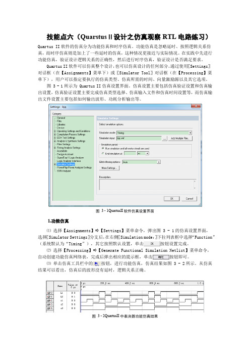
图 3 - 1所示为 Quartus II仿真设置界面。
仿真设置主要包括仿真验证设置和仿真输出设置,仿真验证设置主要完成仿真类型选择、仿真输入文件和仿真时间设置等,而仿真输出文件设置主要包括如何输出波形、功耗分析输出等。
图 3 - 1QuartusII软件仿真设置界面⒈功能仿真⑴选择【Assignments】⇨【Settings】菜单命令,弹出图 3 - 1的仿真设置界面,选择〖Simulator Settings〗分支后,在右侧〖Simulation mode:〗下拉列表框中选择“Function”(系统默认为“Timing”),其它按照默认设置,单击按钮设置完成。
⑵选择【Processing】⇨【Generate Functional Simulation Netlist】菜单命令,自动创建功能仿真网络表,完成后弹出相应的提示框,单击按钮即可。
⑶单击仿真工具栏中的按钮,进行功能仿真,仿真结果如图 3 - 2所示。
从仿真结果可以看出,仿真后的波形没有延时,逻辑关系正确。
图 3 - 2QuartusII中表决器功能仿真结果⒉时序仿真⑴图 3 - 1 中选择〖Simulator Settings〗分支,在右侧〖Simulation mode:〗下拉列表框中选择“Timing”(系统默认值),其它按照默认设置,单击按钮。
eda考试题及答案
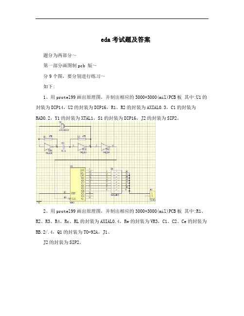
eda考试题及答案题分为两部分~第一部分画图制pcb 版~分9个图,要分别进行练习~如下:1、用protel99画出原理图,并制出相应的3000*3000(mil)PCB板其中:U1的封装为DIP14,U2的封装为DIP16,R1、R2的封装为AXIAL0.3,C1的封装为RAD0.2,Y1的封装为XTAL1,S1的封装为DIP16,J2的封装为SIP2。
2、用protel99画出原理图,并制出相应的3000*3000(mil)PCB板其中:R1、R2、R3、R4、Rc、RL的封装为AXIAL0.4,Rw的封装为VR3,C1、C2、Ce的封装为RB.2/.4,Q1的封装为TO-92A,J1、J2的封装为SIP2。
3、用protel99画出原理图,并制出相应的2000*2000(mil)PCB板其中:R1、R2、R3的封装为AXIAL0.4,R的封装为VR2,UA741的封装为DIP8,JP1、JP2的封装为SIP2。
4、用protel99画出原理图,并制出相应的3000*3000(mil)PCB板其中:R1、R2、R3、R4、R5、R6、R7的封装为AXIAL0.4,U1、U2、DS1的封装为DIP16。
5、用protel99画出原理图,并制出相应的2000*2000(mil)PCB板其中:U1、U2的封装为DIP14,J1、J2的封装为SIP2。
6、用protel99画出原理图,并制出相应的2000*2000(mil)PCB板其中:U1的封装为DIP16,U2、U3的封装为DIP14, J2的封装为SIP3。
7、用protel99画出原理图,并制出相应的2000*3000(mil)PCB板其中:R1、R2、R3、R4、R5、R6、R7的封装为AXIAL0.4,Rw的封装为VR3,U1的封装为DIP8, J1的封装为SIP2。
8、用protel99画出原理图,并制出相应的2000*2000(mil)PCB板其中: U1的封装为DIP16,U2的封装为DIP14,J1的封装为SIP6。
EDA考试必考知识点

EDA考试必考知识点咱先来说说 EDA 这玩意儿哈,这在考试里可重要得很呢!就像你去参加一场刺激的冒险,EDA 知识就是你手中的关键地图。
首先,EDA 的基本概念那是必考的。
啥是 EDA 呢?简单来说,就是电子设计自动化,它能帮工程师们更高效地设计电路和系统。
比如说,有一次我去一个电子厂参观,看到工程师们坐在电脑前,用 EDA软件就像变魔术一样,把复杂的电路设计得井井有条。
那场面,真让人惊叹!然后就是 EDA 工具的使用。
像那些常见的 EDA 工具,比如Cadence、Altium Designer 等等,你得熟悉它们的操作界面、功能模块。
我记得有个学生,在考试前拼命练习工具的使用,结果考试的时候碰到一个相似的题目,轻松就拿下了高分。
再说说硬件描述语言,像 VHDL 和 Verilog 这俩“大佬”。
你得搞清楚它们的语法规则、数据类型、控制结构。
想象一下,你要用这些语言来给电路“说话”,告诉它该怎么做。
这就好比你指挥一个机器人,得把指令说得明明白白。
还有数字电路设计,这也是重点中的重点。
什么组合逻辑电路、时序逻辑电路,都得弄得清清楚楚。
我曾经遇到过一个实际的案例,一个电路出现故障,就是因为时序逻辑没设计好,导致整个系统都乱套了。
另外,系统级设计也是必考的一块儿。
从顶层到底层,怎么把一个大的系统分解成一个个小模块,再把它们整合起来,这可需要不少功夫。
在 EDA 考试中,仿真和验证也是不能忽视的。
你设计好的电路到底行不行,得通过仿真来验证一下。
就像你做好了一道菜,得尝尝味道对不对。
最后,可别忘了综合和布局布线。
这就像是给你的电路找个合适的“家”,让它能舒舒服服地工作。
总之,EDA 考试的必考知识点就像一个个宝藏,你得用心去挖掘、去掌握。
只要你认真学习,多做练习,相信在考试中一定能取得好成绩,顺利开启你的电子设计之旅!加油吧!。
EDA实验设计报告流水灯

EDA实验设计报告流水灯一、实验背景流水灯是一种光电组合组件,它大多由两个简单元件组成,一个是led发光二极管,另一个是电位器,可以改变二极管的亮度。
本实验以FATI0A0话题,使用IMO89C52单片机实现流水灯,探究LED的工作原理和单片机的控制原理。
二、实验目的1、通过练习,掌握FATI0A0开发工具的使用,熟悉FATI0A0的基础开发流程;2、掌握基于PORTA的控制方法,通过调节端口的输出电压,控制LED的亮度和闪烁;3、掌握基于定时器的控制方法,使LED实现流水灯效果;4、掌握电路结构和作用原理,用多种方式实现流水灯效果,利用延时函数编程,启用定时器0、定时器1和定时中断,掌握定时器的设置方法等。
三、实验环境本次流水灯实验由FATI0A0开发平台准备了硬件环境:实验台、IMO89C52单片机、晶振、电源、LED等组成。
四、实验步骤(一)编写程序1.首先利用CY8IDE软件设计并编写流水灯程序,开启定时器,通过定时中断实现LED 的闪烁;2.然后了解定时器1的设置方法,编写流水灯程序,将定时器1设置为内部计数,并设定中断周期;3.最后将定时器1设置为高中断优先级,以确保流水灯的互斥性。
(二)烧写1.连接实验台的FATI0A0和串口,Push连接拨码开关,检查元件布局是否正确;2.将编写的程序烧写到FATI0A0,同时将电源和晶振接到FATI0A0的连接器上;3.然后将烧写好的源代码下载到FATI0A0可编译环境,并在FATI0A0上启动,程序就会运行起来。
(三)验证1.将拉线连接到LED上,先检查LED是否能正常亮灭;2.将程序烧写到FATI0A0后,打开LED,检查流水灯效果,看是否按照要求显示;3.如果实验结果满足要求,实验就成功。
五、结论本次实验熟悉了FATI0A0开发环境的使用,掌握了PORTA的控制方法,熟悉了基于定时器的控制方法,使LED实现流水灯效果,用多种方式实现流水灯效果,利用延时函数编程,启动定时器0、定时器1和定时中断,掌握定时器的设置方法等,有助于更好、更全面地掌握IMO89C52单片机和流水灯的相关知识。
EDA技术习题集及答案

第一章 EDA概述一、填空题1.2000年推出的Pentium 4微处理器芯片的集成度达——万只晶体管。
2.一般把EDA技术的发展分为——、——和——三个阶段。
3.在EDA发展的——阶段,人们只能借助计算机对电路进行模拟、预测,以及辅助进行集成电路版图编辑、印刷电路板(PcB)布局布线等工作。
4.在EDA发展的——阶段,人们可以将计算机作为单点设计工具,并建立各种单元库,开始用计算机将许多单点工具集成在一起使用。
5.EDA设计流程包括——、——、——和——四个步骤。
6.EDA的设计验证包括——、——和——三个过程。
7.EDA的设计输入主要包括——、——和———。
8.文本输入是指采用——进行电路设计的方式。
9.功能仿真是在设计输入完成之后,选择具体器件进行编译之前进行的逻辑功能验证,因此又称为——。
10.时序仿真是在选择了具体器件并完成布局、布线之后进行的时序关系仿真,因此又称为——或——。
11.当前最流行的并成为1EEE标准的硬件描述语言包括————和——。
12.采用PLD进行的数字系统设计,是基于芯片的设计或称之为——的设计。
13.硬件描述语言HDL给PLD和数字系统的设计带来了更新的设计方法和理念,产生了目前最常用的并称之为——的设计法。
14.EDA工具大致可以分为——、——、———、———和——等五个模块。
15.将硬件描述语吉转化为硬件电路的重要工具软件称为——————。
二、单项选择题1.将设计的系统或电路按照EDA开发软件要求的某种形式表示出来,并送入计算机的过程称为( )。
①设计输入②设计输出③仿真④综合2.一般把EDA技术的发展分为( )几个阶段。
①2 ②3 ③4 ④53.AHDL属于( )描述语言。
①普通硬件②行为③高级④低级4.vHDL属于( )描述语言。
①普通硬件②行为③高级④低级5.包括设计编译和检查、逻辑优化和综合、适配和分割、布局和布线,生成编程数据文件等操作的过程称为( )。
数字系统设计与EDA技术课后练习题含答案

数字系统设计与EDA技术课后练习题含答案一、十进制和二进制数转换练习题1:将十进制数87转换为二进制数。
答案1:87的二进制表示为1010111。
练习题2:将二进制数1110101转换为十进制数。
答案2:1110101的十进制表示为117。
练习题3:将十进制数170转换为八进制数。
答案3:170的八进制表示为252。
练习题4:将八进制数243转换为十进制数。
答案4:243的十进制表示为163。
练习题5:将十进制数189转换为十六进制数。
答案5:189的十六进制表示为0xBD。
练习题6:将十六进制数0x3F转换为十进制数。
答案6:0x3F的十进制表示为63。
二、布尔代数和逻辑门电路练习题1:使用逻辑门实现以下布尔代数:Y = (A and B and C) or D答案1:这个布尔代数可以用以下逻辑门实现: +----+A -------| ||AND +--------+B -------| | |+----+ +----v----+C --------------| || OR +----- YD --------------| |+----------+练习题2:设计一个电子逻辑门电路,将两个单字节二进制数相加。
输入是两个二进制数,输出是相加的结果。
假设不会有溢出。
答案2:这个电子逻辑门电路可以用以下连线和逻辑门实现:输入1 --> +-----+--> | |+-----+| | | ADD +--> C3 --------+ +-----+--> || |输入2 --> +-----+--> | | | | | | | ADD |+-----+--> C2 --------+-->| |--> | +--+--+| | ||| | ||+-----+--> ||||||+-----+--> C1 --------+--> 输出其中ADD代表一个加法器电路,C1-C3代表进位。
第一章EDA技术实验基础实验

第一章 技术实验基础实验实验一 用原理图输入法设计一位半加器一、实验目的.熟悉利用Ⅱ的原理图输入方法设计简单组合电路;.通过一个半加器的设计把握利用软件进行电子线路设计的详细流程;.学会对实验板上的进行编程下载,硬件验证自己的设计项目。
二、实验设备及器材配置机一台综合实验开发系统中:基本核心板模块、发光管显示模块、普通键盘模块、下载器、下载线、十针连接线根。
三、实验原理.根据真值表表写出电路的逻辑表达式表 一位半加器真值表其中, 为输入端口,与分别为半加器的和与进位。
其逻辑表达式为:o s a b =⊕ab Co =.根据逻辑表达式进行原理图设计。
注意:在进行原理图设计时,元件之间的连线应尽量避免与元件外的虚线框重合。
四、实验步骤:.为本项工程设计建立文件夹,注意文件夹名不能用中文,且不可带空格。
.根据半价器逻辑表达式进行原理图设计。
.对所设计的工程文件进行编译,排查错误。
.时序仿真,记录时序分析表。
.选择目标芯片。
.引脚锁定。
推荐锁定形式:输入接口选择核心板上接口,与普通键盘模块相连,连接后,可任意选择按键所对应的引脚(例如,选择和,它们所对应的引脚编号为和;输出接口选择核心板上接口,与发光管显示模块相连,连接后,课任意选择发光二级管所对应的引脚(例如选择和,它们所对应的引脚编号为和)。
注:输入输出接口可在核心板上十针接口中任意选择(白色接口除外),对应的引脚可在核心板上的引脚标注中查找。
.编程下载,观察硬件结果。
下载时请下载器形式请选择。
注:如下载后硬件调试没有通过,需重新检查连接,如果修改后重新进行下载,请将下载界面中原有的*文件删除,重新加载一次,然后再下载。
.撰写实验报告册,思考如何利用半加器设计一位全加器。
五、练习题. 请用本实验所作的一位半加器设计一位全加器。
要求利用原理图输入方式。
. 请利用一位全加器设计四位全加器。
要求利用原理图输入方式。
注:本练习主要使学生牢固掌握原理图输入设计方法,同时掌握设计中有关层次的基本概念。
EDA实训报告.doc

设计报告课程名称在系统编程技术任课教师查长军设计题目电子钟班级11通信1班姓名郭丽丽学号1105021006 日期2014-6-25目录一、题目分析 (1)1、总体方框图: (1)2、设计指标: (1)3、功能要求: (1)二、选择方案 (1)三、细化框图 (2)四、编写应用程序并仿真 (2)1、秒计数器 (2)2、分钟计数器 (3)3、时钟计数器 (4)4、整点报时模块 (4)五、全系统联调,画出整机电路,波形图等 (5)1、数字时钟系统总原理图 (5)2、数字时钟系统波形图仿真 (5)六、硬件测试及说明。
(5)1、各部分引脚图 (6)七、结论 (6)1、实验调试结果分析 (6)八、课程总结 (6)九、参考文献目录 (7)十、附录(源程序) (7)1、小时计数器VHDL语言源程序(底层文件) (7)2、分钟计数器VHDL语言源程序(底层文件) (8)3、秒钟计数器VHDL语言源程序(底层文件) (9)4、整点报时报警模块VHDL语言源程序(底层文件) (10)一、题目分析2、设计指标:(1)时间以 24 小时为一个周期;(2)显示时、分、秒;(3)有校时功能,可以分别对时及分进行单独校时,使其校正到标准时间;(4)计时过程具有报时功能,当时间到达整点进行蜂鸣报时并延时2秒。
3、功能要求:1.时钟计数:完成时、分、秒的正确计时并且显示所计的数字;对秒、分 60 进制计数,即从 0 到 59 循环计数,对时 24 进制计数,即从 0 到 23 循环计数。
2.时间设置:手动调节分钟(setfen)、小时(setshi),高定平时有效,可以对分、时进行进位调节,低电平时正常计数。
这样可以对所设计的时钟的时间任意调。
3.清零功能:reset 为复位端,低电平时实现清零功能,高电平时正常计数。
这样可以对所设计的时钟的时间进行清零处理。
4.整点报时功能:当分由 59 进位时,会在整点报时输出端输出高电平,此信号可以通过 LED 点亮检验。
altium designer练习题

altium designer练习题Altium Designer是一款功能强大的电子设计自动化(EDA)软件,广泛应用于电子产品设计和PCB布局。
为了帮助大家更好地掌握Altium Designer的使用技巧,下面将给出一些练习题,旨在提供实践机会,加深对软件的理解和运用。
1. 绘制一个简单的电路图在Altium Designer中创建一个新的电路图,绘制一个简单的电路,例如一个LED灯的电路。
包括电源、电阻、LED灯和电源接地。
确保电路图的连线准确、清晰可读。
2. 添加电源和元件参数在前面绘制的电路图中,给电源和各个元件添加参数。
例如,对于电源,可以设置电压值和电流值;对于电阻,可以设置阻值;对于LED灯,可以设置电压、电流和功率等参数。
3. 创建PCB布局在Altium Designer中创建一个新的PCB文件,根据前面绘制的电路图进行布局。
确保元件的位置合理,连线路径清晰简洁。
利用软件的布局工具,可以自动排列元件,提高生产效率。
4. 进行网络连接在PCB布局中,使用软件提供的功能进行网络连接。
确保连线正确无误,并且符合电路图的要求。
根据需要添加电源和地线,连接各个元件,形成完整的电路板布局。
5. 添加焊盘和丝印在PCB布局中,为各个元件添加焊盘和丝印。
焊盘用于元件的焊接,丝印用于标识元件的名称、值或其他信息。
确保焊盘的大小和形状与元件匹配,丝印的位置清晰可读。
6. 进行布线在PCB布局中,使用软件的布线功能,对各个元件进行适当的布线。
确保信号线和电源线之间的距离足够,以免干扰;同时,避免信号线之间的交叉和干扰。
优化布线路径,使其简洁美观。
7. 生成制造文件在Altium Designer中,生成制造文件,包括Gerber文件、钻孔文件等。
确保生成的文件与PCB布局一致,并符合制造厂商的要求。
可通过软件提供的检查功能进行验证,避免制造中的问题。
这些练习题涵盖了Altium Designer的基本操作和常见任务,帮助初学者熟悉软件界面和功能。
eda课程设计自动演奏

eda课程设计自动演奏一、教学目标本课程的教学目标是使学生掌握eda课程设计自动演奏的基本原理和方法,能够运用所学知识进行简单的自动演奏设计。
1.理解eda的基本概念和原理。
2.掌握自动演奏的基本方法和技巧。
3.能够使用eda工具进行简单的自动演奏设计。
4.能够分析并解决自动演奏过程中遇到的问题。
情感态度价值观目标:1.培养学生对音乐和艺术的热爱和尊重。
2.培养学生的创新精神和团队合作意识。
二、教学内容本课程的教学内容主要包括eda的基本概念和原理,自动演奏的基本方法和技巧。
1.eda的基本概念和原理:介绍eda的基本概念,包括eda的定义、特点和应用范围;讲解eda的基本原理,包括数字信号处理、声音合成和音乐理论。
2.自动演奏的基本方法和技巧:介绍自动演奏的基本方法,包括midi文件编辑、音频处理和虚拟乐器;讲解自动演奏的技巧,包括节奏控制、音色选择和音乐创作。
三、教学方法本课程的教学方法主要包括讲授法、实践法和讨论法。
1.讲授法:通过讲解eda的基本概念和原理,自动演奏的基本方法和技巧,使学生掌握相关知识。
2.实践法:通过让学生实际操作eda工具,进行自动演奏设计,使学生掌握实际操作技能。
3.讨论法:通过分组讨论,让学生分享自己的设计和经验,促进学生之间的交流和合作。
四、教学资源本课程的教学资源包括教材、多媒体资料和实验设备。
1.教材:选用权威、实用的教材,如《eda教程》等。
2.多媒体资料:提供相关的视频、音频和图文资料,如eda软件教程、自动演奏案例等。
3.实验设备:准备计算机、音响设备、midikeyboard等实验设备,为学生提供实践操作的机会。
五、教学评估本课程的评估方式包括平时表现、作业和考试三个部分,以全面客观地评价学生的学习成果。
1.平时表现:通过观察学生在课堂上的参与度、提问和回答问题的情况,以及小组讨论的表现来评估学生的学习态度和理解程度。
2.作业:布置适量的作业,如eda工具的使用练习、自动演奏设计案例分析等,通过学生的作业完成情况评估其掌握程度。
eda乒乓球课程设计

eda乒乓球课程设计一、课程目标知识目标:1. 学生能理解乒乓球运动的基本规则和比赛方法。
2. 学生掌握乒乓球运动的基本技巧,如发球、接球、攻球和防守。
3. 学生了解乒乓球运动的历史和发展,以及我国在乒乓球运动中的成就。
技能目标:1. 学生能够正确使用乒乓球拍,进行基本的发球、接球和击球动作。
2. 学生能够在对战中运用所学技巧,展示良好的战术素养。
3. 学生通过乒乓球锻炼,提高身体协调性、反应速度和团队合作能力。
情感态度价值观目标:1. 学生培养对乒乓球运动的兴趣,积极参与体育锻炼,养成良好的运动习惯。
2. 学生在乒乓球比赛中,学会尊重对手,树立公平竞争的意识。
3. 学生通过乒乓球运动,培养勇敢、自信、坚韧的品质,增强集体荣誉感和团队精神。
4. 学生了解我国乒乓球运动的发展,激发爱国情怀,增强民族自信心。
课程性质:本课程以实践为主,结合理论讲解,注重培养学生的动手能力和实际操作能力。
学生特点:学生处于小学高年级阶段,具有一定的乒乓球基础,好奇心强,活泼好动。
教学要求:教师需关注学生的个体差异,因材施教,确保每个学生都能在课程中收获成长。
同时,注重培养学生的运动兴趣,激发他们积极参与体育活动的热情。
通过课程教学,使学生在乒乓球运动中不断提高,达到预期的学习成果。
二、教学内容1. 乒乓球运动概述- 乒乓球运动的历史与发展- 乒乓球运动的基本规则与比赛方法2. 乒乓球基本技术- 发球技术:正手发球、反手发球- 接球技术:正手接球、反手接球- 攻球技术:正手攻球、反手攻球- 防守技术:挡球、削球、挑球3. 乒乓球战术与应用- 基本战术:快攻、慢攻、旋球、短球- 战术组合:发球抢攻、拉球突袭、防守反击- 战术分析:观察对手,调整战术4. 乒乓球训练方法- 基本动作训练:站位、握拍、摆臂- 技术训练:发球、接球、攻球、防守- 战术训练:模拟比赛,实际操作5. 乒乓球比赛与裁判- 比赛规则:单打、双打、团体赛- 裁判方法:比赛裁判、比分记录教学内容安排与进度:第一课时:乒乓球运动概述,了解运动起源、发展及规则第二课时:乒乓球基本技术(1),学习发球、接球技术第三课时:乒乓球基本技术(2),学习攻球、防守技术第四课时:乒乓球战术与应用,学习战术组合及分析第五课时:乒乓球训练方法,进行基本动作、技术、战术训练第六课时:乒乓球比赛与裁判,熟悉比赛规则,进行实际操作教学内容与课本关联性:本教学内容与体育课本中乒乓球章节内容相符,确保学生能够掌握乒乓球运动的基本知识、技能和战术。
完整word版EDA技术与VHDL复习练习题

EDA技术与VHDL复习练习题 8、GAL16V8的_______不可编程:A:与阵列 B:或阵列>※<习题一 C:输出逻辑宏单元OLMC D:A、B都三、判断题一、填空题1、GAL器件的输出逻辑宏单元OLMC不能实现PAL________1、PLD的中文含义是:。
器件的所有输出形式。
() ASIC的中文含义是:________。
2、2、PAL器件只能一次编程。
()、“与-或”结构的可编程逻辑器件主要由四33、GAL器件只能一次编程。
()____________________、部分构成:________、4、PAL和GAL器件需要使用专门的编程器编程。
____________。
和5、PAL器件可以在系统编程。
()”表示此、可编程逻辑器件结构图中一般用“x46、GAL器件可以在系统编程。
()________。
编程单元为7、PAL器件可以取代GAL器件。
()、可编程逻辑器件结构图中一般用“·”表示58、GAL器件可以取代PAL器件。
()。
此编程单元为________9、GAL器件可以使用紫外线擦除。
()、可编程逻辑器件结构图中无任何标记表示此610、GAL器件OLMC不可编程。
()。
编程单元为________11、GAL器件不能加密。
()、可编程逻辑器件按规模的大小一般分为7。
和_________________答案:和________8、低密度可编程逻辑器件的主要有一、填空题 _________。
1、可编程逻辑器件2、专用集成电路________9、GAL器件取代全部PAL器件。
3、输入电路、可编程“与”阵列、可编程或阵 PAL次编程。
器件只能________10、列、输出电路4、编程连接5、固定连接 ________器件能次编程。
11、GAL6、不连接7、低密度可编程逻辑器件、髙密度可 TTL器件。
取代器件、12GAL________编程逻辑器件8、PAL、GAL9、可以10、一 GAL、器件采用擦除。
EDA技术习题.

第一章EDA技术概述填空题1.一般把EDA技术的发展分为_______、_______和________三个阶段。
2.在EDA发展的_________阶段,人们只能借助计算机对电路进行模拟、预测,以及辅助进行集成电路版图编辑、印刷电路板(PCB)布局布线等工作。
3.在EDA发展的_______阶段,人们可与将计算机作为单点设计工具,并建立各种设计单元库,开始用计算机将许多单点工具集成在一起使用。
4.EDA设计流程包括_________、__________、__________和_________四个步骤。
5.EDA的设计验证包括________、__________和_________。
6.EDA的设计输入方式主要包括________、________和_________。
7.文本输入是指采用_________进行电路设计的方式。
8.功能仿真是在设计输入完成之后,选择具体器件进行编译之前进行的逻辑功能验证,因此又称为_______。
9.时序仿真是在选择了具体器件并完成布局、布线之后进行的时序关系仿真,因此又称为________或_______。
10.当前最流行的并成为IEEE标准的硬件描述语言包括_________和________.11.硬件描述语言HDL给PLD和数字系统的设计带来了更新的设计方法和理念,产生了目前最常用的并称之为_______的设计法。
12.EDA工具大致可以分为________、_______、_______、________以及_____等5个模块。
13.将硬件描述语言转换为硬件电路的重要工具称为_______。
单项选择题1.将设计的系统或电路按照EDA开发软件要求的某种形式表示出来,并送入计算机的过程称为( ).①设计输入②设计输出③仿真④综合2.在设计输入完成后,应立即对设计文件进行()①编辑②编译③功能仿真④时序仿真3.在设计处理工程中,可产生器件编程使用的数据文件,对于CPLD来说是产生()①熔丝图②位流数据③图形④仿真4.在设计处理过程中,可产生供器件编程使用的数据文件,对于FPGA来说是生成()①熔丝图②位流数据③图形④仿真5.在C语言的基础上演化而来的硬件描述语言是()①VHDL②Verilog HDL③AHD④CUPL6.基于硬件描述语言HDL的数字系统设计目前最常用的设计法称为()设计法。
13届4t蓝桥杯eda模拟题

主题:13届4t蓝桥杯EDA模拟题内容:一、引言13届4t蓝桥杯EDA模拟题是蓝桥杯电子设计自动化(EDA)方向的一道经典题目。
本题旨在考察参赛者在EDA领域的知识水平和解决问题的能力。
下面将对这道题目进行详细的分析和解答。
二、题目描述13届4t蓝桥杯EDA模拟题是关于电子设计自动化(EDA)领域的一个实际问题。
题目描述如下:某公司需要设计一个8位的RISC处理器,你需要根据给定的指令集和对应的控制信号,完成以下任务:1. 给出处理器的状态转移图;2. 根据状态转移图,设计电路逻辑,完成对指令的译码功能;3. 给出至少三个任意指令序列,并用状态转移图表示每个指令序列的执行过程。
三、解题步骤为了解答13届4t蓝桥杯EDA模拟题,我们可以按照以下步骤逐步完成:1. 理解题目要求:明确了解题目的需求,分析每个任务的具体要求;2. 掌握RISC处理器基础知识:了解RISC处理器的基本结构和指令集,理解状态转移图的概念;3. 状态转移图设计:根据给定的指令集和控制信号,绘制处理器的状态转移图;4. 电路逻辑设计:根据状态转移图,设计电路逻辑,完成对指令的译码功能;5. 指令序列执行过程的表示:给出至少三个任意指令序列,并用状态转移图表示每个指令序列的执行过程。
四、解题过程详解1. 理解题目要求我们要明确理解题目的要求,明白每个任务需要完成的具体内容。
只有充分理解题目的要求,才能有针对性地进行解题。
2. 掌握RISC处理器基础知识在解答该题之前,我们需要对RISC处理器的基础知识进行了解和掌握。
RISC处理器是一种采用精简指令集的微处理器。
了解其基本结构和指令集,以及如何设计状态转移图是解答本题的基础。
3. 状态转移图设计根据题目所给的指令集和对应的控制信号,我们可以通过分析指令的执行过程,绘制出相应的状态转移图。
状态转移图反映了处理器在执行指令时状态的变化和相应的控制信号。
4. 电路逻辑设计根据状态转移图,我们需要设计相应的电路逻辑,完成对指令的译码功能。
立创eda 技巧

立创eda 技巧
1.利用快捷键提高工作效率:掌握一些常用的快捷键,如
ctrl+c,ctrl+v等,可以大大提高工作效率。
2. 学会使用自动化工具:立创EDA提供了很多自动化工具,如PCB绘制自动化工具、原理图自动化工具等,学会使用这些工具可以减少重复性的工作,提高工作效率。
3. 熟悉软件的各种设置:了解软件的各种设置可以让你更好地利用软件的功能,如设置自己的快捷键、自定义菜单等。
4. 掌握好文档管理:文档管理非常重要,可以让你更好地管理自己的工作,如备份工程、文档归档等。
5. 学习优化设计:通过学习优化设计,可以使你的设计更加稳定、可靠、高效。
可以学习一些优化设计的技巧,如减少电路噪声、优化布线等。
6. 多做练习:练习可以帮助你更好地掌握软件的使用,可以多做一些小项目,如设计一个简单的电路板、绘制一张简单的原理图等。
7. 多和同行交流:和同行交流可以让你更好地了解软件的使用技巧和优化设计的方法,可以加入一些技术交流群组,和其他从事电路设计的人交流。
- 1 -。
FloTHERM V8.1 升级练习题 EDA接口
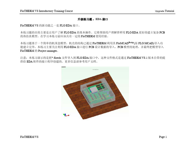
Upgrade Tutorial
FloTHERM/V8
Page 8
FloTHERM V8 Introductory Training Course 升级练习题:EDA 接口 PCB现在已经被处理了。 点击[File/Save as]把处理后的文件另存为一个.flopcb文件。 注意:可以把此文件重新导入到FLO/EDA进行编辑,当此模 型被导入到Flotherm中后,我们还可以进行进一步的修改以定 义不同精度的PCB模型。 点击[File/Transfer and Quit]把此 PCB 模型传入 Flotherm 并退出 FLO/EDA 接口程序。 在 FloTHERM 中查看模型。 注意:从 FLO/EDA 中导入的模型已经被自动附加了网格约 束。这些约束附加到 volume regions 上,而这些 Region 已经把 像散热器和元件组之类的组件包含进去了。
Upgrade Tutorial
FloTHERM/V8
Page 6
FloTHERM V8 Introductory Training Course 升级练习题:EDA 接口 在模型树中展开Layers组件 右击TOP layer并选择Process Layer,导电层处理窗口打开。 注意:图形区显示的图形就是所选层从EDA软件中导入时的结 构情况。下面两个滚动条可以用来对该层进行离散化并产生一 定数量的小铜块来代替该层。 用“Refresh Patch Number”按钮可以计算并查看在当前设置下该 层被划分成了多少小块。 设置滚动条“Resolution of longest side”的值到 25 设置滚动条“Number of %CU bands”的值到 65 点击“Refresh Patch Number”按钮来检查产生了多少个小块(411 个) 点击按钮“Create Patches”
- 1、下载文档前请自行甄别文档内容的完整性,平台不提供额外的编辑、内容补充、找答案等附加服务。
- 2、"仅部分预览"的文档,不可在线预览部分如存在完整性等问题,可反馈申请退款(可完整预览的文档不适用该条件!)。
- 3、如文档侵犯您的权益,请联系客服反馈,我们会尽快为您处理(人工客服工作时间:9:00-18:30)。
Exercise ManualforQuartus® II Software Design Series:FoundationSoftware Requirements to complete all exercisesQuartus II software version 11.0Link to the Quartus II Handbook:/literature/hb/qts/quartusii_handbook.pdfUse the link below to download the design files for the exercises: /customertraining/ILT/Quartus_II_Design_Series_Foundation_11_0_v1.zip2Copyright © 2011 Altera CorporationA-MNL-QII-F-EX-11-0-v1Copyright © 2011 Altera CorporationA-MNL-QII-F-EX-11-0-v13Exercise 14Copyright © 2011 Altera CorporationA-MNL-QII-F-EX-11-0-v1Copyright © 2011 Altera CorporationA-MNL-QII-F-EX-11-0-v15Exercise 1Objectives:∙ Create a project using the New Project Wizard ∙ Name the project ∙ Pick a deviceNote : In these exercises, you’ll crea te a brand new project and complete an existingdesign. You’ll have the choice of creating the design using three different types of design entry: Verilog, VHDL, or as a Quartus II schematic. Where noted, be sure to only follow the instructions appropriate for your choice of design entry method. By the end of the class, you’ll have a final, optimized design, ready for programming into a Cyclone ® IV E FPGA device.Be sure to completely read the instructions for each step and sub-step in this lab manual. Each step first summarizes what you’ll be doing in that step before providing complete instructions. Use the lines next to each step (____) to keep track of your progress or to check off completed steps in the exercises.If you have any questions or problems, please ask the instructor for assistance.Copyright © 2011 Altera CorporationA-MNL-QII-F-EX-11-0-v16Step 1: Create new project for use in the lab exercises____ 1. Unzip the lab project files. In an Explorer window, go toC:\altera_trn\Quartus_II_Software_Design_Series_Foundation . The name of the directory may be shortened to Quartus_II_Foundation or similar on some machines. This will be your lab installation directory. Delete any old lab file folders that may already exist there labeled QIIF*. Double-click the executable file found in that location or the file you downloaded from the link in your class registration email. If you still cannot find this file, ask your instructor for assistance. In the WinZip dialog box, simply click Unzip to automatically extract the files in place to a new folder named QIIF11_0 in the directory mentioned above. Close WinZip. ____ 2. Start the Quartus II software. In the Windows Start menu from the All Programslist, go to the Altera folder and then the Quartus II 11.0 folder. Depending on your operating system, click Quartus II 11.0 (64-bit) or Quartus II 11.0 (32-bit) to start the program. Check with your instructor if unsure. There may also be a shortcut on the desktop. ____ 3. Start the New Project Wizard. You can open it from the Getting Started WithQuartus II Software welcome dialo g that appears. If you’ve closed this window, in the Tasks window on the left side of the Quartus II interface, expand the Start Project folder and double-click Open New Project Wizard . You can also select New Project Wizard… from the File menu. The New Project Wizard appears. If the Introduction screen appears, click Next . ____ 4. Complete the New Project Wizard to create the project. Select one of the workingdirectories shown in Table 1 depending on the type of design entry you want to use. Name the project pipemult and leave the top level entity name pipemult.Table 1. Settings for page 1 of New Project Wizard____ 5. Click Next to advance to page 2.Copyright © 2011 Altera CorporationA-MNL-QII-F-EX-11-0-v17____ 6.On page 2, click the browse button . Navigate to the project directory as theSelect File dialog box may not automatically be pointing there. Select the top-level file pipemult (.v, .vhd, or .bdf, depending on the design entry method you chose in #4). After clicking Open , click Add to add the file to the project. Click Next .Note that this step isn’t really necessary since the design file is already l ocated in the project working directory. The new project would automatically include the design file as part of the project. Files or file directories (libraries) only need to be added on page 2 of the New Project Wizard if they are not located in the project directory. Adding the file to the project removes the warning that the file has not been added.____ 7. On page 3, select Cyclone IV E as the Family . In the Show in ‘Available device’list section, set Package to FBGA , Pin count to 256, and Speed grade to Fastest . This filters the list of available devices. Select the EP4CE6F17C6 device from the Available devices:window.____ 8. Click Next ./////////////////////////////////////////////////////////////////////////////////////////////////////////////8Copyright © 2011 Altera CorporationA-MNL-QII-F-EX-11-0-v1Copyright © 2011 Altera CorporationA-MNL-QII-F-EX-11-0-v1910Copyright © 2011 Altera CorporationA-MNL-QII-F-EX-11-0-v1Copyright © 2011 Altera CorporationA-MNL-QII-F-EX-11-0-v111Copyright © 2011 Altera CorporationA-MNL-QII-F-EX-11-0-v112____ 9. On page 4 (shown below), you can specify third-party EDA tools you may be using.Since these exercises will be done entirely within the Quartus II software without any other tools, click Nextto skip this step.____ 10. The summary screen appears.Copyright © 2011 Altera CorporationA-MNL-QII-F-EX-11-0-v113____ 11. Click Finish .The project is now created.Keep the project open as you continue through the exercises. There is no need to close the project. If you do close the project for some reason, be sure to select Open Project instead of just Open from the File menu (or Open Existing Project from the Tasks window). The Open command is used to simply open a single file instead of a project, preventing the ability to perform many project-based operations, such as compilation.Exercise SummaryCreated a project using the New Project Wizard– Named the project – Picked a deviceEND OF EXERCISE 1Exercise 214Copyright © 2011 Altera CorporationA-MNL-QII-F-EX-11-0-v115Copyright © 2011 Altera Corporation A-MNL-QII-F-EX-11-0-v1Copyright © 2011 Altera CorporationA-MNL-QII-F-EX-11-0-v116Exercise 2Objectives:∙ Create a multiplier and RAM block using the MegaWizard Plug-in Manager tocomplete the design ∙ Create a HEX file to initialize the RAM block using the Memory Editor ∙ Analyze and elaborate the design to check for errorsPipelined Multiplier DesignFigure 1 shows a schematic representation of the top-level design file you will be using today. It consists of a multiplier and a RAM block. Data is fed to the multiplier from an external source and stored in the RAM block, which is also controlled externally. The data is then read out of the RAM block by a separate address control.Figure 1Copyright © 2011 Altera CorporationA-MNL-QII-F-EX-11-0-v117IMPORTANT NOTE: For exercises 2-6, you should either continue working in the Ex1 directory (preferred), or you can open a project (File menu or Tasks window ⇒ Open [Existing] Project ⇒ Select pipemult.qpf and click Open ) found in one of the Ex#directories. The Ex# directories each contain projects in the three versions (schematic, Verilog, VHDL) completed up to the beginning of that exercise in the exercise manual. The Solutions directory contains a Word document with the answers to questions asked in the exercises as well as the final project as it would be set up at the end of exercise 5.Step 1: Build an 8x8 multiplier using the MegaWizard ® Plug-in Manager____ 1. Choose Tools ⇒ MegaWizard Plug-In Manager or double-click MegaWizardPlug-In Manager in the Create Design folder of the Tasks window. In the window that appears, select Create a new custom megafunction variation . Click Next . ____ 2. Select the megafunction to create. On page 2a (shown above), do the following:a. Expand the Arithmetic folder and select LPM_MULT .b. In the drop-down menu, make sure the Cyclone IV E device family is selected.The selection of a device family here lets the MegaWizard Plug-In Manager know what device resources are available as the megafunction is created. You could change the device family if you wanted to create the same megafunction but for a different project that uses a different device.c. Choose VHDL or Verilog HDL output depending on your choice of HDL andexercise directory. If you are using the Schematic exercise, choose either VHDL or Verilog. d. For the name of the output file, type mult . You can add this to the end of thedirectory path or erase the entire path to automatically place the generated megafunction files in the project directory.Copyright © 2011 Altera CorporationA-MNL-QII-F-EX-11-0-v118____ 3. Click Next .///////////////////////////////////////////////////////////////////////////////////////////// \Copyright © 2011 Altera CorporationA-MNL-QII-F-EX-11-0-v11920Copyright © 2011 Altera CorporationA-MNL-QII-F-EX-11-0-v1Copyright © 2011 Altera Corporation22____ 4.On page 3 (General), set the width of the dataa and datab buses to 8 bits if they are not already set. For the remaining settings in this window, use the defaults thatappear.Copyright © 2011 Altera Corporation24____ 5. Click Next .____ 6. On page 4 (General 2), use all the default settings (i.e. datab input does NOT have aconstant value, use unsigned multiplication, and select the default multiplier implementation).____ 7. Click Next.____ 8. On page 5 (Pipelining), choose Yes, I want an output latency of 2 clock cycles .____ 9.Click Next.____ 10.You should now be on page 6 (section 2 of the MegaWizard called EDA). This tab indicates the simulation model file needed to simulate LPM_MULT in an EDAsimulation tool (e.g. ModelSim or some other 3rd-party simulation tool). The lpmsimulation model file should be indicated as shown above. You also have the optionof generating a timing and resource estimation netlist for use by a 3rd-party synthesistools. We are not using any third-party tools, so just click Next.Copyright © 2011 Altera Corporation26____ 11. On page 7, using Table 2 below check the appropriate boxes depending on theDesign Entry Method selected.Table 2. MegaWizard files to generate____ 12. Click Finish to create the megafunction. If a dialog box appears asking if you wantto add the QIP file to the Quartus II project, click Yes .The multiplier is built.If for some reason your megafunction is incorrect or you forgot or missed a checkbox for generating all the required output files, open the MegaWizard Plug-In Manager again from the Tools menu or Tasks window. Select to edit an existing megafunction. Then select the main variation file for the megafunction (mult.v or mult.vhd), and go through the pages of the MegaWizard again (skip around with the tabs at the top) to fix your mistakes or generate the missing file(s). Click Finish to update the megafunction files.Step 2: Create a 32x16 RAM using the MegaWizard Plug-In Manager____ 1.Open the MegaWizard Plug-In Manager again (Tools or Tasks window MegaWizard Plug-In Manager). Select to Create a new custom megafunctionvariation, and click Next.____ 2.Select the megafunction to create. On page 2a (shown above), do the following:a.Expand the Memory Compiler folder and select RAM: 2-PORT.b.As before, choose the Cyclone IV E device family and VHDL or Verilog HDL.c.For the name of the output file,enter ram.____ 3.Click Next.///////////////////////////////////////////////////////////////////////////////////////////////////////////////////////////////// ///28Copyright © 2011 Altera Corporation30Copyright © 2011 Altera CorporationCopyright © 2011 Altera CorporationA-MNL-QII-F-EX-11-0-v13132Copyright © 2011 Altera CorporationA-MNL-QII-F-EX-11-0-v1Copyright © 2011 Altera CorporationA-MNL-QII-F-EX-11-0-v133____ 4. On page 3, select O ne read port and one write port for the Dual –port RAM mode.Select memory size by words .____ 5. Click Next .____ 6. On page 4 (Widths/Blk Type ), set the width of the data_a bus to 16 and the numberof 16-bit words to 32. Select the Memory block type to Auto and Max depth to Auto .____ 7.Click Next twice.34Copyright © 2011 Altera CorporationA-MNL-QII-F-EX-11-0-v1Copyright © 2011 Altera CorporationA-MNL-QII-F-EX-11-0-v135____ 8. On page 7 (Regs/Clkens/Aclrs ), disable the option to register the Read outputport(s) ‘q’. Accept the remaining default settings.____ 9. Click Next 2 times.____ 10. On page 10 (Mem Init ), click Yes, use this file for the memory content data.Once enabled, type in the file name ram.hex . You’ll be creating this file next, but you can enter it now so you don’t have to go back into the MegaWiza rd later.____ 11. Click Next .Copyright © 2011 Altera CorporationA-MNL-QII-F-EX-11-0-v136____ 12. On page 11, the altera_mf simulation model file is displayed as being needed tosimulate this function in a 3rd -party EDA simulation tool. Click Next . ____ 13. Choose the same files to generate for ram as you selected for mult earlier (Step 1,#11). Click Finish to close the wizard and then Yes to add the Quartus II IP file to the project.You have now created the two components needed for this design. Now you will create the HEX file needed to initialize the contents of the RAM.Step 3: Create HEX file using the Memory Editor____ 1. From the Tasks window, in the Create Design folder, double-click Create NewDesign File . (You may have to change the Tasks Flow to Full Design.) You couldalso go to the File menu and select Newor clickin the toolbar.____ 2. In the New dialog box, expand the Memory Files category and select Hexadecimal(Intel-Format) File.____ 3. Click OK .Copyright © 2011 Altera CorporationA-MNL-QII-F-EX-11-0-v137____ 4. In the memory size dialog box, choose 32 as the number of words and 16 as theword size.____ 5. Click OK.The Memory Editor now displays your memory space. If your memory space is not displayed exactly as above, you can change the number of cells per row (View menu) to 16, the memory radix (View menu) to Hexadecimal , and the address radix to Decimal .____ 6. Highlight all of the memory locations in your memory space. Right-click and selectCustom Fill Cells . ____ 7. Use the Custom Fill Cells dialog box to enter your own values to initialize yourmemory. You can enter any values you want. Do one of the following:a. Repeating Sequence: Enter a series of numbers separated by commas orspaces to be repeated in memory. b. Incrementing/Decrementing: Enter a start value and another value bywhich to increment or decrement the start value.____ 8. Save the file as ram.hex in the project directory (you may have to navigate to theproject directory again before you save). Close ram.hex.Copyright © 2011 Altera CorporationA-MNL-QII-F-EX-11-0-v138Step 4: Instantiate and connect design blocks according to design entry method Choose ONE of the following procedures based on your design entry method (VHDL, Verilog, or Schematic). Follow only the directions for your selected design entry method and then proceed to Step 5. VHDLPerform these instructions only if you are using VHDL.____ 1. Open pipemult.vhd . You can use the Open command from the File menu, click thetoolbar button, or double-click the top-level entity in the Project Navigator. You can also double-click Open Existing Design File in the Create Design folder of the Tasks window.This is the top-level file for the design. Normally, you would have to instantiate both ram and mult and connect them together. In the interest of time, the file has been almost completed for you, but it is missing the instantiation of the multiplier.____ 2. Open the file mult.cmp . Copy the component declaration from mult.cmp and pasteit into the architecture declaration section of pipemult.vhd where indicated. ____ 3. Close mult.cmp .____ 4. Open the file mult_inst.vhd . Copy the contents of mult_inst.vhd (the componentinstantiation) and paste into the architecture body of pipemult.vhd where indicated. Change the following signal names in the instantiation:clock_sig to clk1 dataa_sig to dataa datab_sig to datab result_sigtomult_to_ram____ 5. Save pipemult.vhd . ____ 6. Close mult_inst.vhd .____ 7. Continue to Step 5: Check the design .VerilogPerform these instructions only if you are using Verilog entry.____ 1. Open pipemult.v . You can use the Open command from the File menu, click thetoolbar button, or double-click the entity in the Project Navigator. You can also double-click Open Existing Design File in the Create Design folder of the Tasks window.Copyright © 2011 Altera CorporationA-MNL-QII-F-EX-11-0-v139This is the top-level file for the design. Normally, you would have to instantiate both ram and mult and connect them together. In the interest of time, the file has been almost completed for you, but it is missing the instantiation of the multiplier.____ 2. Open the file mult_inst.v . Copy the contents of mult_inst.v (the componentinstantiation) and paste into the body of pipemult.v where indicated. Change the following signal names in the instantiation:clock_sig to clk1 dataa_sig to dataa datab_sig to datab result_sigtomult_to_ram____ 3. Close mult_inst.v . ____ 4. Save pipemult.v .____ 5. Continue to Step 5: Check the design .SchematicPerform these instructions only if you are using schematic entry.____ 1. Open pipemult.bdf . You can use the Open command from the File menu, click thetoolbar button, or double-click the entity in the Project Navigator. You can also double-click Open Existing Design File in the Create Design folder of the Tasks window.This is the top-level schematic file for the design. Normally, you would have to instantiate both ram and mult sub-designs and connect them together manually. In the interest of time, the schematic file has been almost completed for you, but it is missing the ram and mult blocks and the output pins q[15..0].____ 2. In the schematic file, double-click any empty space in the schematic so that theSymbol window appears. In the Symbol window, click to expand the symbols defined in the Project folder. Double-click the mult symbol. Click the left mouse button to place the symbol inside the schematic file where indicated.Note: The three ports on the left side of the multiplier should line up exactly with the wires coming from the input pins (no X’s). If not, you may not have specified the multiplier parameters correctly when configuring the megafunction. If this is the case, hit the Esc key to cancel the symbol placement, reopen the MegaWizard Plug-In Manager, and select Edit an existing megafunction variation to open and edit the mult megafunction to fix the problem and regenerate the symbol.____ 3. Right-click on the mult symbol and choose Properties . In the Symbol Propertiesdialog box, change the Instance name: from inst to mult_inst . Click OK .Copyright © 2011 Altera CorporationA-MNL-QII-F-EX-11-0-v140____ 4. Double-click an open area again to reopen the Symbol window. This time, select theram symbol and place it in the schematic file where indicated.Note: With ram , the lower 4 ports on the left side of the symbol should line up with the wires coming from the input pins. The data port should be unconnected.____ 5. As you did with mult, use the Symbol Properties dialog box to change the name ofthe ram instantiation from inst to ram_inst . ____ 6. Open the Symbol window again and this time, as a shortcut, type output in the Name:field.The Symbol window found the output symbol automatically by name.____ 7. Click OK and place the output pin near the output port of the inst2 register symbol.Double-click the pin_name and change it to q[15..0]. ____ 8.Click on the bus drawing tool , found in the schematic editor toolbar, and draw thebus connections between mult (result ) and ram (data ).Your resulting schematic should look like the above figure.____ 9. Save pipemult.bdf .Copyright © 2011 Altera CorporationA-MNL-QII-F-EX-11-0-v141Step 5: Check the design____ 1. From the Processing menu, select Start ⇒ Start Analysis & Elaboration .Analysis and elaboration checks that all the design files are present and connections have been made correctly. It also establishes the project hierarchy.____ 2. Click OK when analysis and elaboration is completed. If there are any errors detailedin the Messages window, check your connections or return to the MegaWizard Plug-In Manager for either megafunction to fix the problem (select to edit an existing megafunction instead of creating a new one). You can safely ignore any blue warnings that appear.Feel free to explore the Project Navigator that now contains the complete project hierarchy.//////Exercise Summary∙ Generated a multiplier and RAM using the MegaWizard Plug-In Manager andincorporated into a design ∙ Created a HEX file for RAM initialization using the Memory Editor ∙ Checked the design files using Analysis and ElaborationEND OF EXERCISE 2Exercise 342Copyright © 2011 Altera CorporationA-MNL-QII-F-EX-11-0-v143Copyright © 2011 Altera Corporation A-MNL-QII-F-EX-11-0-v1Copyright © 2011 Altera CorporationA-MNL-QII-F-EX-11-0-v144Exercise 3Objectives:∙ Perform full compilation∙ Locate information in the Compilation Report∙ Explore cross-probing capabilities by viewing logic in various windowsTable 3 – Compilation ReportCopyright © 2011 Altera CorporationA-MNL-QII-F-EX-11-0-v145Step 1: Compile the design____ 1. Select Start Compilation from the Processing menu or clicklocated in thetoolbar to perform a full compilation of the design. You can also double-clickCompile Design in the Tasks window. A dialog box will appear to indicate when the compilation is complete. ____ 2. Click OK .////Step 2: Gather information from the Compilation Report)The Compilation Report provides all information on design processing. You use it to understand how the compiler interpreted your design and to verify results. It is organized by compiler executables, with each one generating its own folder. By default, the Compilation Report opens when any processing begins and displays the Flow Summary Section when that process finishes.____ 1. From the Flow Summary section of the Compilation Report , record the Total logicelements , Total memory bits , number of Embedded multiplier 9-bit elements and Total pins in the table at the beginning of this exercise (Table 3).From these results, you can see that this design is currently using only dedicated device resources (i.e. embedded memory, embedded multipliers) and no logic other than the registers included within these resources. ///Copyright © 2011 Altera CorporationA-MNL-QII-F-EX-11-0-v146//////////////////////////////////____ 2. Expand the Fitter folder in the Compilation Report . Locate the Resource Sectionfolder. From the Resource Utilization by Entity table, record again in Table 3, the resource counts for the mult and ram sub-designs.///////////////////////////////////Copyright © 2011 Altera CorporationA-MNL-QII-F-EX-11-0-v147____ 3. From the Control Signals table, also in the Resource Section , record the controlsignals found and their fan-out.///////////////////////////////////In the next few steps, you will take a look at some additional ways to analyze the results of your compilation and determine the location of the output registers.Copyright © 2011 Altera CorporationA-MNL-QII-F-EX-11-0-v148Step 3: Explore the design logically using the RTL ViewerThe RTL Viewer allows you to view a logical representation of an analyzed design graphically. It is a very helpful tool for debugging HDL synthesis results.____ 1. From the Tools menu, open the RTL Viewer (under Netlist Viewers ). You can alsoaccess the RTL Viewer from the Compile Design section of the Tasks window.You should see the diagram shown above. The output register block is namedinst2[15..0] in the schematic version of the project, but the rest of the diagram is the same for all three versions. This is a graphical view displaying the logicalrepresentation of the design. Currently it shows the I/O, the instantiation of the mult and ram sub-designs, and an additional set of output registers. Notice the registers are external to the memory block per the original design.//////////////////////////////////____ 2. Select the ram sub-design to highlight it. The outline of the block turns bright redwhen the block is selected. Right-click and select Ungroup Selected Nodes .Copyright © 2011 Altera CorporationA-MNL-QII-F-EX-11-0-v149The ram block is now displayed with all of the input and output buses expanded. This operation is helpful when you want to see how individual bits are connected. This operation can be performed on internal blocks and I/O./////////////////////////////////Copyright © 2011 Altera CorporationA-MNL-QII-F-EX-11-0-v150Select the ram sub-design again if it was deselected. Right-click and select Group Related Nodes .This returns the RTL Viewer to the previous view.____ 3. Double-click on the ramsub-design block.You have now descended the hierarchy into the ram sub-design. As a result, the view changes to the above (or similar) image. This shows that the ram sub-design is made up of a single megafunction block called altsyncram . You can continue double-clicking blocks to descend the hierarchy to its lowest level: single-bit RAM functions. Let’s view this lowest level of the hierarchy in a different way.///////////////////////////////____ 4. Double-click in any empty space.This returns the viewer to the top-level view of the design. If you’ve descended further into the hierarchy, you may need to do this a few times to return to the top.。
