Sliding-window Motion Artifact Rejection for Functional NearInfrared Spectroscopy
brother P-touch PT-7600 说明书
编辑和出版声明 本说明书在兄弟工业株式会社的监督下编辑和出版,其中包括最新的产品说明和 规格。 本说明书的内容和本产品的规格如有变更,恕不另行通知。 Brother 公司保留在不另行通知的情况下,对其中所包含的规格和材料进行更改的 权利,由于信任所引用的材料所造成的损害 (包括结果性损害),包括但不限于 印刷上的错误和其他与此出版物相关的错误, Brother 将不承担任何责任。 商标 Brother 标识是兄弟工业株式会社的注册商标。 Brother 是兄弟工业株式会社的注册商标。 © 2010 Brother Industries, Ltd. 版权所有。
P-touch 打印机 为避免引起火灾、损坏、触电或震动,请遵守下列指导。 请勿让 P-touch 打印机以任何方式受潮。 请勿触摸打印头附近的任何金属部件。打 印头在使用期间温度极高并在使用之后短 期内保持高温状态。请勿直接用手触摸。
打印头
请勿分解 P-touch 打印机。检查、设置和 修理 P-touch 打印机,应联系出售本打印 机的零售商或当地的授权维修中心。 本打印机使用塑料包装。 为避免引起窒息 危险, 请将塑料袋保存在儿童不易接触到 的地方。 使用或存放期间,当您发现异味、发热、 变色、变形或任何异常情形时,应立即断 开电源,取出电池,并停止使用。 为防止受损,请勿跌落或碰撞本机器。
1. 启动前准备工作 .................................................................... 1
拆开打印机包装 ......................................................................................1 概述 ..........................................................................................................2 顶视图和底视图 ..........................................................................................2 键盘和液晶显示屏 ......................................................................................3 背景灯 ..........................................................................................................4 电源 ..........................................................................................................4 电源适配器 .................................................................................................. 4 电池 ..............................................................................................................5 充电电池组 .................................................................................................. 6 色带盒 ......................................................................................................8 安装色带盒 .................................................................................................. 8 开启 / 关闭打印机 .................................................................................10
Ingenia MotionLab安装与配置指南说明书
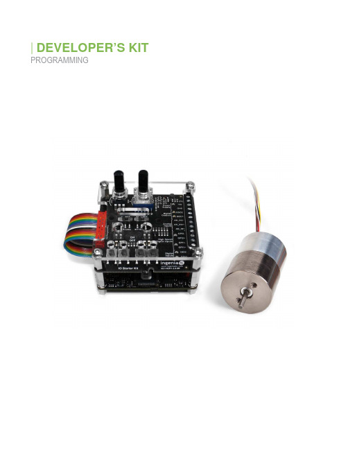
DEVELOPER’S KIT PROGRAMMINGCopyright © 2019 Sensata Technologies, Inc. Rev. 04/11/2023 Installing & Configuring MotionLab1.Head to Ingenia MotionLab and click on the ‘Download ’ button in the software section.2.Run the prompted download and complete the setup as you would any other program.3.While downloading, connect the provided Flash drive to your computer 4.Run MotionLab.5.If your drive has an update, click on ‘New FW Available ’ then click on automatic update in thebox that pops up.6.Select your drive by clicking near the green box above. This will take you to a new screen. If youdo not see your drive:a.Ensure that your drive is connected to the computer.b.Click on scan again.7.Click on ‘Load’ and use the directory to pull up the contents of the flash drive. Load the .xdc filenamed after the actuators part number. If you don’t know the part number, check the engravings on the actuator itself.8.Once loaded, click on ‘Write’ to load the parameters to the drive. At this point your drive is fullyconfigured and ready to use.Move OverviewThis section will discuss the different functions and parameters found within the ‘Move’ window. Entering this window is done by clicking on the top of the main Motionlab window. This action will bring up a new window.Homing: Sets the read value of the shaft location1.Homing method - Chooses the type of homing procedure. I suggest using either NegativeMechanical Limit or Positive Mechanical limit for initial calibration. These methods will push the shaft all the way in, or all the way out respectively.2.Homing offset - This is the value that will be written to the corresponding homing position. In theabove picture, the current position of the shaft will be set to -500 counts.Position: Moves shaft to a designated positionTARGET:1.Target position – sets the shaft to the specified position.a.You can set an accurate desired position with the box to the right of the bar.2.Step size – sets a wanted step size for use with the ‘- step’ and the -+ Step’ buttons. PROFILE:1.Profile velocity – controls speed that shaft attains wanted position.2.Profile acceleration – controls acceleration of shaft towards wanted position.3.Profile deceleration – controls stop speed of shaft when reaching wanted position. LIMITS:1.Minimum absolute position – sets lower limit of shaft position2.Maximum absolute position – sets upper limit of shaft position.THRESHOLDS:1.Position window – sets accepted range of position values relative to target value in which thecontroller will stop trying to correct the shafts current position.2.Position window time – sets the measuring time for the controller to check if position is correct3.Following error window – has a similar concept as the position window. I suggest making thisvalue the same as the position window.4.Following error timeout – sets a measurement time for the shaft position. If the shaft is not in thespecified position for this time an error will be produced.*CONTROL LOOP:1.Proportional gain – sets proportional constant (Kp’) for PID loop.2.Integral gain – sets integral constant (Ki’) for PID loop3.Derivative gain – sets derivative constant (Kd’) for PID loop.4.Integral AW gain – sets integral anti-windup (kii’) constant5.Velocity FF gain – Sets velocity feedforward (Kffv’) constant6.Acceleration FF gain – sets acceleration feedforward (kffa’) constant.7.Integral Limit – puts a limit on the integral gain’s contribution.*This window only controls the position PID loop. It does not affect the force and velocity PID.Velocity: Increases speed that shaft moves toward end of stroke.TARGET:1.Target Velocity – sets desired instantaneous velocity value2.Manual increments – sets a wanted step size for use with the ‘- Target velocity’ and the ‘+ Targetvelocity’ buttons.PROFILER:1.Profile acceleration - Defines the maximum allowed acceleration.2.Profile deceleration - Defines the maximum allowed deceleration.LIMITS:1.Maximum profile velocity - Define the maximal allowed velocity in each direction during a profiledmotion.THRESHOLDS:1.Velocity window – Defines the acceptable window for error. A higher window means a lowertolerance for reaching a specific target velocity.2.Velocity window time- Indicates the configured time (in ms), during which the actual velocitywithin the velocity window is measured. If the actual velocity is within the velocity window for a velocity window time, the target is reached3.Velocity threshold- Indicates the configured zero velocity threshold time. If the actual velocity isabove the velocity threshold longer than velocity threshold time, the motor is seen as moving.4.Velocity threshold time- Indicates the configured zero velocity threshold time. If the actualvelocity is above the velocity threshold longer than velocity threshold time, the motor is moving. **CONTROL LOOP:1.Proportional gain – sets proportional constant (Kp’) for PID loop.2.Integral gain – sets integral constant (Ki’) for PID loop3.Derivative gain – sets derivative constant (Kd’) for PID loop.4.Integral AW gain – sets integral anti-windup (kii’) constant5.Acceleration FF gain – sets acceleration feedforward (kffa’) constant.6.Integral Limit – puts a limit on the integral gain’s contribution.**This only controls the velocity PID loop. The force/position PID is unaffected.Force: Increases Push/Pull force on shaftTARGET:1.Target force – Sets the desired instantaneous torque value.2.Manual increment – Sets incremental torque value for use with ‘- Target force’ and ‘+ Targetforce’ buttons.PROFILER:1.Force Slope – defines slope of force increase towards target force.LIMITS:1.Negative force limit – indicates maximum pulling force2.Positive force limit – indicates maximum pushing forceTHRESHOLDS:1.Force window – Defines the acceptable window for torque/force error. A higher window means alower tolerance for reaching a specific target torque/force.2.Force window time - Indicates the configured time (in ms), during which the actual torque withinthe torque window is measured. If the actual torque is within the torque window for a torquewindow time, the target torque is set as reached.***CONTROL LOOP:1.Proportional gain – defines proportional constant (Kp’) value.2.Integral gain – defines integral constant (Ki’) value3.Cutoff frequency – sets desired cutoff frequency of lowpass filter.***This only controls the force PID loop.Multi-Point: Moves shaft to multiple locations in successionPosition:1.Position box – Sets the desired position2.Capture – Captures the desired position3.Repeat Sequence – Toggles repeat actions after the entire list of positions is reached.4.Pause before repeating – Sets delay before repeat sequence is performedAdditional Position Parameters:1.Profile Parametersa.Profile velocity – controls speed that shaft attains wanted position.b.Profile acceleration – controls acceleration of shaft towards wanted position.c.Profile deceleration – controls stop speed of shaft when reaching wanted position.2.Limit Parametersa.Minimum absolute position – sets lower limit of shaft positionb.Maximum absolute position – sets upper limit of shaft position.3.Threshold Parametersa.Position window – sets accepted range of position values relative to target value in whichthe controller will stop trying to correct the shafts current position.b.Position window time – sets the measuring time for the controller to check if position iscorrectc.Following error window – has a similar concept as the position window. I suggest makingthis value the same as the position window.d.Following error timeout – sets a measurement time for the shaft position. If the shaft isnot in the specified position for this time an error will be produced.Advanced Motion Control:1.Position Loop Parametersa.Proportional gain – sets proportional constant (Kp’) for PID loop.b.Integral gain – sets integral constant (Ki’) for PID loopc.Derivative gain – sets derivative constant (Kd’) for PID loop.d.Integral AW gain – sets integral anti-windup (kii’) constante.Velocity FF gain – Sets velocity feedforward (Kffv’) constantf.Acceleration FF gain – sets acceleration feedforward (kffa’) constant.g.Integral Limit – puts a limit on the integral gain’s contribution. Oscillation: Moves the shaft back and forth between specified boundsInitial Positioning:1.Oscillate around: defines the initial position that the shaft will oscillate around.Oscillation:1.Mode: allows you to choose between a sinusoidal or square oscillation profile.2.Amplitude: defines zero to peak oscillation height. The actual oscillation travel distance will betwice this value3.Frequency: defines the frequency of oscillation.4.Interpolation Period:Additional Position Parameters:1.Profile Parametersa.Profile velocity – controls speed that shaft attains wanted position.b.Profile acceleration – controls acceleration of shaft towards wanted position.c.Profile deceleration – controls stop speed of shaft when reaching wanted position.2.Threshold Parametersa.Position window – sets accepted range of position values relative to target value in whichthe controller will stop trying to correct the shafts current position.b.Position window time – sets the measuring time for the controller to check if position isCorrectAdditional Oscillation Parameters:1.Limit Parametera.Minimum absolute position – sets lower limit of shaft positionb.Maximum absolute position – sets upper limit of shaft position.2.Threshold Parametersa.Following error window – has a similar concept as the position window. I suggest makingthis value the same as the position window.b.Following error timeout – sets a measurement time for the shaft position. If the shaft isnot in the specified position for this time an error will be produced.Advanced Motion Control:1.Position Loop Parametersa.Proportional gain – sets proportional constant (Kp’) for PID loop.b.Integral gain – sets integral constant (Ki’) for PID loopc.Derivative gain – sets derivative constant (Kd’) for PID loop.d.Integral AW gain – sets integral anti-windup (kii’) constante.Velocity FF gain – Sets velocity feedforward (Kffv’) constantf.Acceleration FF gain – sets acceleration feedforward (kffa’) constant.g.Integral Limit – puts a limit on the integral gain’s contribution.Program:This section will display the controller’s ability to run and create macros. Entering this window is done by clicking ‘Program’ on the top of the main Motionlab window. This action will bring up a new window. The image below shows an example of an oscillate function. See Ingenia Knowledge Base for examples of how to execute most move functions. Any other inquiries can be sent to *******************Program Control:1.Write reserved memory2.Load – Brings up explorer to choose a preexisting file.3.Save All – Saves the current macro set up.4.Write All – Writes all macros to the controller5.Set Interruption – Writes interruptions to the controller. Used with Interrupt Designation.6.Run – Runs the selected macro.7.Stop – Force stops all programs.Copyright © 2023 Sensata Technologies, Inc. Rev. 04/11/2023 Sensata Technologies, Inc. (“Sensata”) data sheets are solely intended to assist designers (“Buyers”) who are developing systems thatincorporate Sensata products (also referred to herein as “components”). Buyer understands and agrees that Buyer remains responsiblefor using its independent analysis, evaluation and judgment in designing Buyer’s systems and products. Sensata data sheets have beencreated using standard laboratory conditions and engineering practices. Sensata has not conducted any testing other than thatspecifically described in the published documentation for a particular data sheet. Sensata may make corrections, enhancements,improvements and other changes to its data sheets or components without notice. Buyers are authorized to use Sensata data sheets with the Sensata component(s) identified in each particular data sheet. HOWEVER,NO OTHER LICENSE, EXPRESS OR IMPLIED, BY ESTOPPEL OR OTHERWISE TO ANY OTHER SENSATA INTELLECTUALPROPERTY RIGHT, AND NO LICENSE TO ANY THIRD PARTY TECHNOLOGY OR INTELLECTUAL PROPERTY RIGHT, ISGRANTED HEREIN. SENSATA DATA SHEETS ARE PROVIDED “AS IS”. SENSATA MAKES NO WARRANTIES ORREPRESENTATIONS WITH REGARD TO THE DATA SHEETS OR USE OF THE DATA SHEETS, EXPRESS, IMPLIED ORSTATUTORY, INCLUDING ACCURACY OR COMPLETENESS. SENSATA DISCLAIMS ANY WARRANTY OF TITLE AND ANYIMPLIED WARRANTIES OF MERCHANTABILITY, FITNESS FOR A PARTICULAR PURPOSE, QUIET ENJOYMENT, QUIETPOSSESSION, AND NON-INFRINGEMENT OF ANY THIRD PARTY INTELLECTUAL PROPERTY RIGHTS WITH REGARD TO SENSATA DATA SHEETS OR USE THEREOF.All products are sold subject to Sensata’s terms and conditions of sale supplied at SENSATA ASSUMES NOLIABILITY FOR APPLICATIONS ASSISTANCE OR THE DESIGN OF BUYERS’ PRODUCTS. BUYER ACKNOWLEDGES ANDAGREES THAT IT IS SOLELY RESPONSIBLE FOR COMPLIANCE WITH ALL LEGAL, REGULATORY AND SAFETY-RELATEDREQUIREMENTS CONCERNING ITS PRODUCTS, AND ANY USE OF SENSATA COMPONENTS IN ITS APPLICATIONS,NOTWITHSTANDING ANY APPLICATIONS-RELATED INFORMATION OR SUPPORT THAT MAY BE PROVIDED BY SENSATA. Mailing Address: Sensata Technologies, Inc., 529 Pleasant Street, Attleboro, MA 02703, USA.CONTACT US Americas +1 (760) 597 7042**************************Europe, Middle East & Africa +1 (760) 597 7042support @se Asia Pacific *************************.com China +86 (21) 2306 1500Japan +81 (45) 277 7117Korea +82 (31) 601 2004India +91 (80) 67920890Rest of Asia +603-5566 6001Macro Access:-Lets you choose which macro to edit.-Macro 0 will work on controller startup.Macro Programming:1.Add – Adds the selected item from the dropdown box to the current macro.2.Dropdown – Selects the program function that you want to add to the macro. Requires the ‘Add’button to place.3.Remove All – Deletes all functions from the current macro.4.Save – Saves the current macro.5.Write – Writes the selected macro to the controller6.Copy/Move – Copies or moves the current macro to a macro number of your choosing.7.Current Function Properties – Allows you to edit the highlightedInterrupt Designation:1.Active – Checking the box will allow the interrupt to be written to the controller. You need topress ‘Set Interruptions’ in the Program Control section.2.Source – Selects the type of interrupt you want to use.3.Macro – Designates the macro that will be called when the interrupt is triggered.。
详解Metrics应用监控指标的使用说明
详解Metrics应⽤监控指标的使⽤说明⽬录引⽤Metric库RegistryGauge(仪表)Counter(计数器)Meter()Histogram(直⽅图)Timer(计时器)HealthCheck(健康检查)JMX报表HTTP报表其它报表MetricSet第三⽅库MetricsforSpring基本⽤法XML风格的配置java注解的⽅式题前:做过虚拟化级别、系统级别、容器级别监控;应⽤级别监控有哪些⽅法可以做?Metrics是个很好的选择。
java、python、go均可⽀持。
Metrics可以为你的代码的运⾏提供⽆与伦⽐的洞察⼒。
作为⼀款监控指标的度量类库,它提供了很多模块可以为第三⽅库或者应⽤提供辅助统计信息,⽐如Jetty, Logback, Log4j, Apache HttpClient, Ehcache, JDBI, Jersey, 它还可以将度量数据发送给Ganglia和Graphite以提供图形化的监控。
Metrics提供了Gauge、Counter、Meter、Histogram、Timer等度量⼯具类以及Health Check功能。
引⽤Metric库将metrics-core加⼊到maven pom.xml中:<dependencies><dependency><groupId>com.codahale.metrics</groupId><artifactId>metrics-core</artifactId><version>${metrics.version}</version></dependency></dependencies>将metrics.version设置为metrics最新的版本。
现在你可以在你的程序代码中加⼊⼀些度量了。
RegistryMetric的中⼼部件是MetricRegistry。
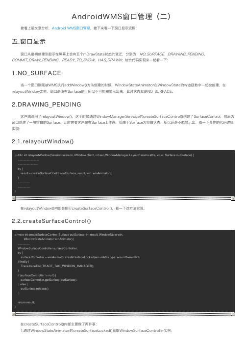
AndroidWMS窗口管理(二)
...................... mSurfaceController = new WindowSurfaceController(mSession.mSurfaceSession,
attrs.getTitle().toString(),width, height, format, flags, this, windowType, ownerUid); mSurfaceFormat = format; w.setHasSurface(true); } .................................. mService.openSurfaceTransaction(); try { mSurfaceController.setPositionInTransaction(mTmpSize.left, mTmpSize.top, false); mSurfaceController.setLayerStackInTransaction(getLayerStack()); mSurfaceController.setLayer(mAnimLayer); } finally { mService.closeSurfaceTransaction(); } mLastHidden = true; return mSurfaceController; }
斑马技术公司DS8108数字扫描仪产品参考指南说明书

verifying signed artifacts报错的解决方法 -回复
verifying signed artifacts报错的解决方法-回复问题:verifying signed artifacts报错的解决方法引言:在软件开发和应用分发过程中,数字签名用于确保软件包或文件的完整性和认证来源。
然而,当使用工具或平台进行验证过程时,有时会遇到“verifying signed artifacts报错”的问题。
本文将分步介绍如何解决这个问题,并提供一些可能出现的原因和解决方法。
第一步:理解问题在开始解决问题之前,先了解一下“verifying signed artifacts报错”是什么意思。
当我们在使用工具或平台验证数字签名时,系统会对文件进行验证,并比对该文件的签名与公钥是否匹配。
如果出现报错,通常意味着该文件的签名无效或已被篡改。
第二步:检查环境和资源首先,确保你使用的工具或平台处于正常工作状态,并且具备所需的资源。
有时,验证过程需要连接到外部服务器或使用特定的密钥库。
确保网络连接稳定并检查所需的授权文件或证书是否存在且有效。
第三步:检查数字签名相关的问题在继续进行深入排查之前,需要确认问题是否与数字签名本身相关。
验证签名时,可能会出现以下几种情况:1. 签名无效:签名可能已过期、使用的密钥已被吊销、签名证书已被篡改或不匹配等。
检查签名证书的相关信息,并确保其有效性。
2. 签名算法错误:验证签名需要使用正确的算法。
检查所使用的工具或平台是否支持所需的算法,并确保配置正确。
3. 私钥或公钥错误:验证签名需要使用正确的密钥对。
确保所使用的密钥对与签名一致,并且私钥和公钥没有被篡改。
第四步:检查文件完整性如果数字签名本身没有问题,接下来需要检查文件的完整性。
在签名过程中,通常会对文件进行散列(hash)。
验证签名时,系统会计算文件的散列,并将其与签名中的散列进行比对。
如果文件被篡改,那么散列值就会不匹配。
1. 文件传输错误:在文件传输过程中,存在文件损坏的风险。
确保文件的传输是完整的,并与原始文件保持一致。
known issues with graphics drivers -回复
known issues with graphics drivers -回复在计算机科学和图形处理中,图形驱动程序是连接操作系统和图形硬件之间的重要组成部分。
它们负责管理计算机系统的图形输出,确保图形和视频在屏幕上正确显示。
然而,许多计算机用户经常遇到图形驱动程序的问题。
这些问题可能会导致屏幕闪烁、图像失真、游戏性能下降等各种问题。
本文将探讨与图形驱动程序相关的已知问题,并提供解决这些问题的步骤。
首先,有时候安装了最新的图形驱动程序后,用户可能会发现屏幕闪烁或出现黑屏。
这可能是由于驱动程序与操作系统或其他软件之间的兼容性问题导致的。
要解决这个问题,用户可以尝试以下步骤:1. 卸载当前的图形驱动程序:在Windows操作系统中,用户可以打开设备管理器,展开“显示适配器”选项,右键单击当前的图形驱动程序并选择“卸载”。
在macOS中,用户可以前往“系统偏好设置”>“显示”>“图像”选项卡,然后单击“高级”按钮并选择“恢复默认值”。
2. 更新操作系统:操作系统的更新通常包含修复与图形驱动程序相关的问题的补丁。
用户可以查看操作系统的更新通知,并确保安装最新的更新。
3. 下载并安装最新的图形驱动程序:用户可以访问计算机制造商的官方网站或图形卡制造商的网站,然后下载并安装最新的图形驱动程序。
在安装之前,用户应该确保下载适用于其操作系统和图形卡型号的正确版本。
4. 执行图形驱动程序的清洁安装:有时,以前安装的版本可能会与新版本的图形驱动程序产生冲突。
为了避免这种情况,用户可以使用“显示驱动程序卸载工具”等第三方软件来清除所有以前安装的图形驱动程序文件和设置,并执行全新的图形驱动程序安装。
其次,用户还可能遇到图形驱动程序导致的图像失真问题。
这可能表现为图像模糊、颜色不准确或分辨率不正确。
要解决这个问题,用户可以尝试以下步骤:1. 调整图形设置:用户可以打开图形驱动程序的控制面板(例如NVIDIA 控制面板,AMD Radeon设置等),然后调整相关的图形设置,如亮度、对比度、饱和度等,以优化图像质量。
Projector Image Tool 版本3.20 用户手册说明书
mediacreationtool 命令行参数
mediacreationtool 命令行参数
MediaCreationTool是一款微软开发的软件,用于从Microsoft服务器下载Windows ISO映像。
它支持命令行参数,允许用户通过命令行来启动和配置该工具。
以下是MediaCreationTool支持的一些命令行参数:
/acceptEula:接受软件使用条款。
/install:执行安装程序。
/?, /h, /help:显示帮助信息。
/u:指定用户名。
/p:指定密码。
/target:指定目标文件夹路径,用于保存下载的ISO 映像。
/lang:指定语言。
/sku:指定要下载的Windows版本(例如,Home、Professional等)。
/arch:指定系统架构(例如,x86、x64等)。
/version:指定要下载的Windows版本号(例如,10、
11等)。
/bitsclipper:禁用位剪裁器(bitsclipper)。
/nocopy Protection:禁用复制保护。
这些命令行参数可以帮助用户定制MediaCreationTool 的行为,以满足特定的需求。
请注意,命令行参数的具体使用方法和效果可能因MediaCreationTool的不同版本而有所差异。
在使用命令行参数时,建议查阅官方文档或参考相关资源以获取准确的信息和指导。
1PPC控制器故障代码查询重要

Rexroth IndraControl VCP 20Industrial Hydraulics Electric Drivesand ControlsLinear Motion andAssembly Technologies PneumaticsServiceAutomationMobileHydraulicsRexroth VisualMotion 10 Multi-Axis Machine Control R911306327 Edition 01Troubleshooting GuideAbout this Documentation Rexroth VisualMotion 10 Troubleshooting Guide DOK-VISMOT-VM*-10VRS**-WA01-EN-PRexroth VisualMotion 10Multi-Axis Machine ControlTroubleshooting Guide DOK-VISMOT-VM*-10VRS**-WA01-EN-P Document Number, 120-2300-B323-01/ENPart of Box Set, 20-10V-EN (MN R911306370)This documentation describes …•the use of VisualMotion Toolkit for assitance in diagnostics •the proper steps for indentifing diagnostic faults • and the suggested remedies for clearing faults Description ReleaseDateNotes DOK-VISMOT-VM*-10VRS**-WA01-EN-P 08/2004Initial release© 2004 Bosch Rexroth AGCopying this document, giving it to others and the use or communicationof the contents thereof without express authority, are forbidden. Offendersare liable for the payment of damages. All rights are reserved in the eventof the grant of a patent or the registration of a utility model or design(DIN 34-1).The specified data is for product description purposes only and may notbe deemed to be guaranteed unless expressly confirmed in the contract.All rights are reserved with respect to the content of this documentationand the availability of the product.Bosch Rexroth AGBgm.-Dr.-Nebel-Str. 2 • D-97816 Lohr a. MainTel.: +49 (0)93 52/40-0 • Fax: +49 (0)93 52/40-48 85 • Telex: 68 94 21Bosch Rexroth Corporation • Electric Drives and Controls5150 Prairie Stone Parkway • Hoffman Estates, IL 60192 • USATel.: 847-645-3600 • Fax: 847-645-6201/Dept. ESG4 (DPJ)This document has been printed on chlorine-free bleached paper.Title Type of DocumentationDocument TypecodeInternal File Reference Purpose of Documentation Record of Revisions Copyright Validity Published byNoteRexroth VisualMotion 10 Troubleshooting Guide Table of Contents I Table of Contents1VisualMotion Tools for Diagnosing1-1 The Diagnostics Menu.............................................................................................................1-1System Diagnostics.................................................................................................................1-1Tasks Diagnostics...................................................................................................................1-3Drive Overview….....................................................................................................................1-42Monitoring and Diagnostics2-12.1System Diagnostics - Codes and Message...................................................................................2-1Parameters..............................................................................................................................2-2DriveTop..................................................................................................................................2-32.2Control Startup Messages.............................................................................................................2-4PPC Boot-Up Sequence..........................................................................................................2-4Control Firmware Sequence....................................................................................................2-42.3Status Messages (001-199)...........................................................................................................2-5001 Initializing System.............................................................................................................2-5002 Parameter Mode...............................................................................................................2-5003 Initializing Drives...............................................................................................................2-5004 System is Ready...............................................................................................................2-5005 Manual Mode....................................................................................................................2-5006 Automatic Mode: ABCD....................................................................................................2-5007 Program Running: ABCD.................................................................................................2-6008 Single-Stepping: ABCD....................................................................................................2-6009 Select Parameter Mode to Continue................................................................................2-6010 Breakpoint Reached: ABCD.............................................................................................2-6018 Please cycle power to continue........................................................................................2-6019 Executing User Initialization Task....................................................................................2-62.4Warning Messages (201-399).......................................................................................................2-7201 Invalid jog type or axis selected........................................................................................2-7202 Drive %d is not ready.......................................................................................................2-7203 Power Fail detected..........................................................................................................2-7204 Sercos ring was disconnected..........................................................................................2-8205 Parameter transfer warning in Task %c...........................................................................2-8207 Axis %d position limit reached..........................................................................................2-8208 Lost Fieldbus Connection.................................................................................................2-9209 Fieldbus Mapping Timeout...............................................................................................2-9210 File System Defrag: %d completed................................................................................2-10211 Program- & Data memory cleared..................................................................................2-10212 Option Card PLS Warning, see ext. diag.......................................................................2-10213 Sercos cycle time changed.............................................................................................2-11214 PCI Bus Cyclic Mapping Timeout...................................................................................2-11 DOK-VISMOT-VM*-10VRS**-WA01-EN-PII Table of Contents Rexroth VisualMotion 10 Troubleshooting Guide215 RECO I/O Failure, see ext. diag.....................................................................................2-11216 Control PLS %d warning, see ext. diag..........................................................................2-12217 PCI Bus Communication, see ext. diag..........................................................................2-12218 PCI Bus Register Mapping Timeout...............................................................................2-13219 PCI Bus Lifecounter Timeout.........................................................................................2-13220 Excessive deviation in PMG%d, see ext. diag...............................................................2-13221 Excessive Master Position Slip Deviation......................................................................2-13222 ELS Config. Warning, see ext. diag...............................................................................2-14223 PCI Bus reset occurred, cyclic data are invalid..............................................................2-14225 System booted................................................................................................................2-14226 RS485 Serial Communication Error (port X1%d)...........................................................2-15227 Control Over-temperature Warning................................................................................2-15228 Control - SYSTEM WARNING.......................................................................................2-152.5Shutdown Messages (400 - 599).................................................................................................2-16400 EMERGENCY STOP......................................................................................................2-16401 Sercos Controller Error: %02d........................................................................................2-16402 Sercos Config. Error: see ext. diag................................................................................2-16403 System Error see ext. diag.............................................................................................2-17405 Phase %d: Drive did not respond...................................................................................2-17407 Drive %d Phase 3 Switch Error......................................................................................2-17409 Sercos Disconnect Error.................................................................................................2-18411 Drive %d Phase 4 Switch Error......................................................................................2-18412 No drives were found on ring..........................................................................................2-18414 Parameters were lost......................................................................................................2-19415 Drive %d was not found..................................................................................................2-19416 Invalid Instruction at %04x..............................................................................................2-19417 SYSTEM ERROR: pSOS #%04x...................................................................................2-19418 No program is active.......................................................................................................2-20419 Invalid Program File: code = %d....................................................................................2-20420 Drive %d Shutdown Error...............................................................................................2-20421 User Program Stack Overflow........................................................................................2-20422 Parameter transfer error in Task %c..............................................................................2-21423 Unimplemented Instruction.............................................................................................2-21425 Instruction error: see Task %c diag................................................................................2-21426 Drive %d is not ready.....................................................................................................2-22427 Calc: invalid table index %d............................................................................................2-22428 Calc: division by zero......................................................................................................2-22429 Calc: too many operands................................................................................................2-22430 Calc: invalid operator......................................................................................................2-23431 Calc error: see Task %c diag.........................................................................................2-23432 Calc: too many nested expressions...............................................................................2-23433 Setup instruction outside of a task.................................................................................2-23434 Axis %d configured more than once...............................................................................2-23435 Axis %d is not assigned to a task...................................................................................2-24436 General Compiler Error: %04x.......................................................................................2-24438 Invalid Axis Selected: %d...............................................................................................2-24DOK-VISMOT-VM*-10VRS**-WA01-EN-PRexroth VisualMotion 10 Troubleshooting Guide Table of Contents III439 Axis %d: Invalid Motion Type.........................................................................................2-24440 I/O Transfer Error: see task diag....................................................................................2-25450 Event %d: invalid event type..........................................................................................2-25451 Invalid event number ‘%d’..............................................................................................2-25452 More than %d event timers armed.................................................................................2-25453 Homing param. transfer error: %d..................................................................................2-25454 Axis %d homing not complete........................................................................................2-26459 Axis %d target position out of bounds............................................................................2-26460 Invalid program %d from binary inputs...........................................................................2-26463 Ratio command: invalid ratio..........................................................................................2-26464 Can't activate while program running.............................................................................2-27465 Drive %d config. error, see ext. diag..............................................................................2-27467 Invalid ELS Master Option..............................................................................................2-27468 ELS adjustment out of bounds.......................................................................................2-27470 Axis %d velocity > maximum..........................................................................................2-28474 Drive %d cyclic data size too large.................................................................................2-28477 Axis D: probe edge not configured.................................................................................2-28478 Calc: operand out of range.............................................................................................2-28483 Parameter Init. Error: see Task %c diag........................................................................2-29484 Control SYSTEM ERROR..............................................................................................2-29486 Sercos Device %d is not a drive.....................................................................................2-29487 CAM %d is invalid or not stored.....................................................................................2-29488 CAM Error: See Task %c diag........................................................................................2-30489 More than %d CAM axes selected.................................................................................2-30490 System Memory Allocation Error....................................................................................2-30492 Programs were lost, see ext. diag..................................................................................2-30496 Can't execute this instruction from an event..................................................................2-31497 Limit switch config. error, see ext. diag.........................................................................2-31498 Drive %d Shutdown Warning..........................................................................................2-32499 Axis number %d not supported in this version...............................................................2-32500 Axis %d is not referenced...............................................................................................2-32501 Drive %d comm. error, see ext. diag..............................................................................2-33502 ELS and cams not supported in this version..................................................................2-33504 Communication Timeout.................................................................................................2-33505 Axis %d is not configured...............................................................................................2-33508 User Watchdog Timeout.................................................................................................2-33509 Control System Timing Error (%d).................................................................................2-34515 PLC Communications Error............................................................................................2-34516 More than %d registration functions enabled.................................................................2-34519 Lost Fieldbus/PLC Connection.......................................................................................2-35520 Fieldbus Mapping Timeout.............................................................................................2-35521 Invalid Virtual Master ID: %d..........................................................................................2-36522 Invalid ELS Master ID: %d..............................................................................................2-36523 IFS status, facility = 0x%x..............................................................................................2-36524 Hardware Watchdog timeout..........................................................................................2-36525 I/O Configuration error, see ext. diag.............................................................................2-36 DOK-VISMOT-VM*-10VRS**-WA01-EN-PIV Table of Contents Rexroth VisualMotion 10 Troubleshooting Guide526 Sercos Multiplex Channel Config, see ext. diag.............................................................2-37527 Control Initialization Error, see ext. diag.........................................................................2-38528 System Event %d Occurred...........................................................................................2-38529 Invalid ELS Group ID: %d...............................................................................................2-38530 CAM %d is active, can't overwrite..................................................................................2-39531 Invalid variable for Fieldbus/PCI Bus Mapping...............................................................2-39532 Power fail brown out condition detected.........................................................................2-39533 Multiple instances of index CAM: %d found...................................................................2-39534 Hardware Version Not Supported..................................................................................2-40539 Invalid Parameter Number..............................................................................................2-40540 Option Card PLS error....................................................................................................2-40541 Link Ring Error, see ext. diag.........................................................................................2-41542 PLC Cyclic Mapping Timeout.........................................................................................2-42543 PCI Bus Runtime Error...................................................................................................2-42544 RECO I/O Failure, see ext. diag.....................................................................................2-42545 Invalid Coordinated Articulation Function ID: %d...........................................................2-43546 Multiple Instance of Coordinated Articulation Function with ID: %d...............................2-43547 Task %c Coordinated Articulation Error, see ext. diag...................................................2-43548 Invalid Kinematic Number: %d.......................................................................................2-43549 Fieldbus Initialization Error.............................................................................................2-43550 User Initialization Task Timeout.....................................................................................2-44551 Master Slip Config. Error, see ext. diag..........................................................................2-44552 Excessive Master Position Slip Deviation......................................................................2-44553 Invalid Parameter Detected, see C-0-2002....................................................................2-44554 Excessive Deviation in PMG%d, see ext. diag...............................................................2-45555 PCI Bus Register Mapping Timeout...............................................................................2-45556 PCI Bus Lifecounter Timeout.........................................................................................2-45557 PMG%d Maximum allowed deviation window is Zero....................................................2-45558 PMG%d Only 1 axis parameterized...............................................................................2-46559 PMG%d Number of offsets does not match number of Axis..........................................2-46560 PMG%d Max. allowed dev. window is larger than 25% of Modulo................................2-46561 PMG%d Offset is larger than Modulo.............................................................................2-46562 PMG%d Parameterized Axis is not in system................................................................2-46563 Invalid Task Specified, Must be A-D..............................................................................2-46564 PMG%d Invalid configuration, see ext. diag...................................................................2-46565 Axis %d: Configuration error, see ext. diag....................................................................2-47566 Filter sample rate and cutoff frequency mismatch.........................................................2-47567 ELS Config. Error, see ext. diag.....................................................................................2-47568 Axis %d: Assigned Task is Not Defined.........................................................................2-48570 ELS Max. Vel. Exceeded, see ext. diag.........................................................................2-48571 No Program Found.........................................................................................................2-49572 PCI Bus reset occurred, cyclic data is invalid.................................................................2-49573 CAM %d is being built....................................................................................................2-49575 ELS Master for ELS Group %d is invalid........................................................................2-49576 Event for input I%d is already armed, cannot arm again...............................................2-50577 Restored non volatile memory from compact flash........................................................2-50DOK-VISMOT-VM*-10VRS**-WA01-EN-PRexroth VisualMotion 10 Troubleshooting Guide Table of Contents V578 Virtual Master %d Exceeded Its Max. Vel., see ext. diag...............................................2-50579 Group %d Exceeded Its Jog Velocity, see ext. diag......................................................2-51580 pROBE Error Occurred in Task:0x%04X.......................................................................2-51581 Probe Function for Axis # is locked by the PLC.............................................................2-51582 Integrated PLC: PLC Stopped in Operation Mode.........................................................2-51583 Integrated PLC: Internal System Error...........................................................................2-51584 ELS System Master %d is invalid, see ext. diag............................................................2-51585 Drive %d separate deceleration not supported..............................................................2-52586 Master Encoder Card Error, see ext diag.......................................................................2-522.6Integrated PLC Status Messages................................................................................................2-536001 Integrated PLC: Running..............................................................................................2-536002 Integrated PLC: Stopped..............................................................................................2-536002 Integrated PLC: Stopped at Breakpoint........................................................................2-532.7Integrated PLC Error Codes........................................................................................................2-530016 Integrated PLC: Software Watchdog Error...................................................................2-530019 Integrated PLC: Program Checksum Error..................................................................2-530020 Integrated PLC: Fieldbus Master Error.........................................................................2-540021 Integrated PLC: I/O Update Error.................................................................................2-542000 Integrated PLC: Internal SIS System Error..................................................................2-542001 Integrated PLC: Internal Acyclic Access Error.............................................................2-542002 Integrated PLC: Internal Acyclic Memory Error............................................................2-542003 Integrated PLC: PLC Configuration Error.....................................................................2-552004 Integrated PLC: File Access Error................................................................................2-552005 Integrated PLC: Internal Fatal Task Error....................................................................2-556011 Integrated PLC: PLC Program Stopped in Operation Mode........................................2-556012 Integrated PLC: General Error.....................................................................................2-552.8Communication Error Codes and Messages...............................................................................2-56!01 Sercos Error Code # xxxx...............................................................................................2-56!02 Invalid Parameter Number..............................................................................................2-57!03 Data is Read Only...........................................................................................................2-57!04 Write Protected in this mode/phase...............................................................................2-57!05 Greater than maximum value.........................................................................................2-57!06 Less than minimum value...............................................................................................2-57!07 Data is Invalid.................................................................................................................2-57!08 Drive was not found........................................................................................................2-57!09 Drive not ready for communication.................................................................................2-57!10 Drive is not responding...................................................................................................2-57!11 Service channel is not open...........................................................................................2-57!12 Invalid Command Class..................................................................................................2-57!13 Checksum Error: xx (xx= checksum that control calculated).........................................2-58!14 Invalid Command Subclass............................................................................................2-58!15 Invalid Parameter Set.....................................................................................................2-58!16 List already in progress..................................................................................................2-58!17 Invalid Sequence Number..............................................................................................2-58!18 List has not started.........................................................................................................2-58!19 List is finished.................................................................................................................2-58 DOK-VISMOT-VM*-10VRS**-WA01-EN-P。
如何在自动化测试脚本中处理Windows系统弹窗
如何在自动化测试脚本中处理Windows系统弹窗在进行自动化测试的过程中,您可能会遇到Windows系统弹窗。
这些弹窗可能是由操作系统、浏览器或其他应用程序引起的,它们经常会导致测试脚本中的错误或异常,从而使测试无法完成或产生误报结果。
因此,在自动化测试中处理Windows系统弹窗非常重要。
在本文中,我们将描述几种方法来解决这个问题。
一、使用AutoIt工具AutoIt是一个免费的Windows自动化工具,它可以模拟用户操作,包括鼠标点击、键盘输入以及处理Windows系统弹窗。
以下是使用AutoIt工具处理Windows系统弹窗的步骤:1、安装AutoIt软件,并运行其脚本编辑器。
2、编写脚本,该脚本模拟用户操作来处理弹窗。
例如,以下示例展示了如何通过单击“确定”按钮来处理一个弹窗:WinWait("确认", "是否要保存更改?")ControlClick("确认", "", "Button1")这段代码等待名为“确认”的窗口,其中包括一个名为“是否要保存更改?”的文本标签。
然后,它单击名为“Button1”的按钮,该按钮被指定为“确定”按钮。
3、在测试脚本中包含这段AutoIt脚本代码。
当测试脚本遇到弹窗时,AutoIt脚本会自动执行,并处理弹窗。
二、使用Sikuli工具Sikuli是一个开源自动化工具,它使用图像识别技术来匹配和处理屏幕上的图像。
以下是使用Sikuli工具处理Windows系统弹窗的步骤:1、安装Sikuli软件,并启动其脚本编辑器。
2、编写脚本,在其中包括针对弹窗的处理步骤。
例如,以下示例展示了如何使用Sikuli处理Chrome浏览器中的弹窗:wait("chrome_screenshot.png")click("chrome_button.png")这段代码等待名为“chrome_screenshot.png”的屏幕截图出现,该截图显示了Chrome浏览器中的弹窗。
CrysAlisPro User Guide
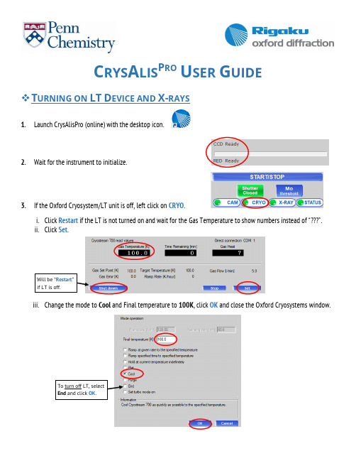
C RYS A LIS P RO U SER G UIDE❖T URNING ON LT D EVICE AND X-RAYSunch CrysAlisPro (online) with the desktop icon.2.Wait for the instrument to initialize.3.If the Oxford Cryosystem/LT unit is off, left click on CRYO.i.Click Restart if the LT is not turned on and wait for the Gas Temperature to show numbers instead of “”.ii.Click Set.Will be “Restart”if LT is off.iii.Change the mode to Cool and Final temperature to 100K, click OK and close the Oxford Cryosystems window.To turn off LT, selectEnd and click OK.4.If the X-ray generator is off, left click on X-RAY.i.Click Set kV, mA, X-ray.ii.Select Default and click OK.iii.Close the window when Voltage is 50.0 and Current is 1.00.Note: The generator window cannot be closed while the X-rays are being ramped up.5.X-ray generator will turn off automatically after 6 hours. If you’d like to turn them off manually, click Set kV, mA, X-ray,select Off and click OK.❖G ETTING S TARTED (SETTING UP AN EXPERIMENT) 1.Click on START/STOP.2.Click on Start new.3.Click on Edit to setup experiment info.4.Click on Browse root folder and locate your lab’s folder in the D:\DATA drive and click OK (click No when asked tochange root folder).5.Change the name of the experiment (check Penn database or sign-up board) and click Exit.e.g. 6874a (# differs between labs, letter is used if multiple crystals of the same sample are being tested)Will be “ClearFolder” if thename is taken.Please do notoverwriteanything. Usethe next letter.❖C ENTERING THE C RYSTAL1.Click Mount or press on the keyboard, this will open the centering interface.Note: If the door is open, press and hold both “Motion Enable” buttons in the enclosure or the goniometer will not move. Alternatively, you can close the door and press the “Doors OK” button.2.Click Home or Center and mount the goniometer head, do not overtighten. Be careful not to bump the beamstop,collimator or coldstream nozzle.3.Click Center (either Center will work) to begin centering (hold down Motion Enable buttons to allow movement).4.Cycle through 0, 90, 180 and 270 phi orientations while centering the crystal at each position. Use the knobsfacing you on the gonio head to adjust the position shown on the camera.5.Once centered, click Exit, gently close the door and press the Doors OK button.❖S CREENING,P RE-E XPERIMENT AND S TRATEGY1.Click the Screen button using default exposure time.Note: If you have tried several crystals and they are all weak, you can increase the exposure time by clicking and adjusting the value in the Exposure time box. It is beneficial to find a good sample BEFORE the pre-experiment.2.Examine the images to ensure you have well-defined spots with no rings/streaks or overlaps. If you have troubleseeing spots, make sure the contrast is at Level 1 (255) and you can change the image color scheme as well.3.Once screening is complete, you should check the results before continuing to the Pre-Experiment.i.High % fit of predicted cell to observed spotsii.Reasonable unit cell (volume and lattice)iii.Well diffracting sample and good quality reflectionsa)If you have a 50-70% fit, then you might have a twinnedcrystal, try another and if it persists, you may continue.b)Check the density of your crystal sample (d = MW/V x 1.66 x Z),a reasonable density is 1.2 to 2.0 g/cm3.c)If you have a moderately diffracting or weakly diffractingsample, try another crystal, if it persists but the reflectionslook well-defined, you may continue.4.Click Pre-Exp to begin the pre-experiment with default exposure time (estimated from screening process).Note: The pre-experiment is a more intensive screening where more frames are collected to better determine exposure times, unit cell and the orientation matrix.5.Once the pre-experiment is finished, the strategy module will openautomatically.Note: Double check the pre-experiment results are consistent with thescreening results. (% of fit reflection and unit cell)Note: If you closed the Experiment Strategy window, the only way to re-open it is to click START/STOP, then Resume all/pre-experiment; recalculate strategy, and then select the “pre_xxxx.run” file. If you want to Screen a different crystal, you must start over. Click START/STOP, then Start New and change the name of the experiment before continuing.6.Click Lattice Wizard in the top right of the Experiment Strategy window.7.Click Lattice transformation.8.Select aP for Triclinic P (should always be on the bottom) and click OK.9.Click Close to exit the Lattice wizard. A window will pop up informing you of the unit cell change, click Yes. Thestrategy module will re-open with recalculated exposure times.10.aP should be the new Cell and the Lauegroup should be 1.11.Under Strategy parameters, change theResolution to 0.77 for heavy atomcompounds (contains elements heavierthan Cl) or 0.83 for light atomcompounds (contains only Cl or lighter).12.Click Advanced to open the StrategyAdvanced Options window.13.Select Use constraints, and One kappa range restriction and change themin to -80 and max to 80, click OK.(kappa restriction prevents icing for long collections)14.Under Strategy mode, use the dropdown menu to select Complete redundant data and change the value to 4 if thecrystal may be higher symmetry than triclinic and 6 if the crystal can only be triclinic.15.The checkbox for Friedel mates and Detector Distance value can be left as is. (the only reason to increase detectordistance is if you have a twinned crystal with a lot of overlapping spots).16.Exp time can be left as is or adjusted (we like to change it to a whole number, a half or an interval of 5).17.Click Calculate New Strategy (might have to change exp time again).18.Make note of the total experiment time and the experiment finish time.19.Click Autochem/Movie/Cryo/Red.20.Enter the Expected chemical formula.21.If the experiment will finish in the middle of thenight or another user will not use the diffractometerafter you, check the Auto cryo device shutdown.22.Click AutoChem settings.23.Select Single trial and use the dropdown menu to select ShelXT.24.Click OK, then OK again to exit Experiment options.25.Click Start Experiment.26.CrysAlisPro will begin automatically processing the data every 25 frames and attempt a solution when the datacompleteness reaches ~40%.Note: When the collection is finished allow it to run a final integration, scaling and AutoChem. You can find the AutoChem files (.res, .hkl and .cif_od) in the struct folder of your corresponding experiment.•If the automatic data processing and solution are satisfactory, you can use the files in the struct to finish the structure. If you would like to manually process the data (we prefer to cutoff the resolution at 0.77Å or 0.83Å) then continue to the next section.❖M ANUALLY P ROCESSING THE D ATAunch CrysAlisPro (red) with the desktop icon.2.Locate the experiment you are trying to open. Select it and click Open selected. (If it’s not automatically listed, clickBrowse experiment, locate the folder, click on the xxxx.par file, click Open, and then Open selected.)3.Left-click or move cursor on Crystal RED, then click Full auto unit cell finding.4.Check that the PEAK TABLE has a good fit (80-100%). If not, you might have a twin and will need to process thedata as a twin. This is done using the Ewald explorer – reciprocal space interface in the Lattice wizard.5.Click Data Reduction, then move cursor over Data Reduction. Then select Data reduction with options.6.The Proffit interface will open. Check that theselected cell and lattice extinctions match.Click Next >.7.Step 2 is useful if you need to change the startor end frame (due to icing or other issues).Click Next >.8.Click Clear data from previous run and Clear alldata from tmp to delete all info from previousprocessing runs. Then click Edit special pars.9.In the special parameters window,check Use resolution limits and clickEdit limits.10.Click Edit high limit and change to 0.77Å for heavy atom compoundsand 0.83Å for light atom compounds (no element heavier than Cl). Then click OK and OK in the special parameters window.11.Select Smart background and click Next >. This isused if the X-ray background is high and/orirregular throughout the dataset. Automaticintegration uses Average background.12.Check the outlier rejection and make sure itmatches previous lattice selections.Click Next >.13.Click Change output name and enter a newoutput name (e.g. 8010a_v1), Click OK. Thisis important so no files will be overwritten.14.Check the Automatic structure solution box.This will generate a new struct folder withyour new output .res and .hkl.Note: If you forget to select this, only an .ins and .hklwill be generated in the primary experiment folder.Open the .ins in Olex2 and SOLVE with ShelXT.15.Click AutoChem options and select SingleTrial and ShelXT, then click OK.16.Click Finish. CrysAlis Pro will integrate,determine the space group and scale.17.If the resulting .res and .hkl files in thecorresponding struct folder are satisfactory,you may finish refining the structure.18.To further inspect the data collection and reduction results, click in the left toolbar.❖U SEFUL N OTES AND COMMANDS•To go to Home position, click in the left toolbar. Make sure CCD tab is selected and type “gt a 0 0 0 0 180” (goto all omega# theta# kappa# phi# detector distance#)•If you forget to select Auto cryo device shut down during the Strategy setup, you can do so after the experiment has started. Click Data Collection and click on “Off: Autocryo Shutdown”. It should now read “On: AutocryoShutdown.”。
Silicon Motion
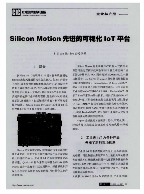
入 门级 人 机 接 口 ( HMI )是 O s p r e y开 方 式 平
台的理想应用 。I o T 设备需要一个人机接 口来访 问 系统架构 ,而小型和低功耗 的可视化触摸系统是本 地用户接 口控制的完美搭配。您可通过将触摸显示 器连接到 O s p r e y 来创建应用。 触摸屏可连接到内置 U S B 集线器或通过 串行端 口进行连接。 U S B集线器
清 1 9 2 0 x 1 0 8 0 。单 显 示最 高为 1 9 2 0 x 1 2 0 0 。 S M7 5 0 2 D引 擎包 括 一 个 前 端 色 彩 空 间 转换 器
开发的可视化 l o T平台。想像一下用作数字相框 以 显示数字照片的家 电控制面板 , 包括当今 的智能手
级标牌产品使用专为工业应用设计 的组件 ,可降低
功 耗且 占地小 。工业 级 H MI 、 测试 设备 、 P O S和 医用
应 用 范 围广 泛 , O s p r e y提 供 了 用 于产 品应 用 设 计 和
●双 数字 视 频 R G B输 出 ( 2 x l 8位 或单 2 4 位 ) 。O s p r e y 使用 2 4 位进行 H D M I 输出。 ●分辨率支持 : 从 V G A 6 4 0 x 4 8 0至最高 的全高
够满足 建立在成熟技术上 的可视化 I o T应用 的小 型、低功耗和低预算要求。这些设备都具有寿命周 期承诺 以满足工业级应用的要求 ,并按工业温度等 级提供 。O s p r e y 是专为工业级产品开发而设计的开 放式平 台, 能够更快地引进和开发 I o T产 打印机或读卡器 。入门
度 。传感 器和 诊断 数据 ( 本 地 和通过 网络 )可 通过
高中英语读后续写积累情绪篇(1)知识清单(1)

2025年高中英语读后续写素材积累1——情绪篇(1)开心1.The joy of acplishment filled my heart, as if each cell in my body was dancingwith glee.成就的快乐填满了我的心,仿佛我身体的每个细胞都在快乐地舞蹈。
2.Her smile, as bright as the morning sun, warmed my soul and brought joy to myday.她的笑容如同早晨的阳光般灿烂,温暖了我的灵魂,给我的一天带来了欢乐。
ughter echoed through the room, a reminder of the simple pleasures of lifethat bring us such happiness.笑声在房间里回荡,提醒我们生活中的简单乐趣能带给我们如此大的快乐。
4.With every passing moment, my happiness grew, like a flower blooming in thesun.随着时间的流逝,我的快乐像阳光下绽放的花朵一样增长。
5.The sight of the children playing happily filled me with a sense of profound joy.看到孩子们快乐地玩耍,我心中充满了深深的快乐。
6.Her eyes sparkled with happiness, reflecting the joy that filled her heart.她的眼睛闪烁着快乐的光芒,反映出她心中满满的喜悦。
7.The feeling of being loved is indescribable, a joy that transcends words and fillsthe heart.被爱的感觉无法用言语描述,那是一种超越语言的快乐,填满了整个心灵。
verifying signed artifacts报错的解决方法 -回复
verifying signed artifacts报错的解决方法-回复Verifying Signed Artifacts: A Step-by-Step Troubleshooting GuideIntroduction:In this article, we will explore the common issues and troubleshooting steps associated with the "verifying signed artifacts" error. Verifying signed artifacts is a crucial process in software development and deployment, ensuring that the digital signature attached to a file or artifact is valid and has not been tampered with. However, sometimes these verifications may fail, leading to errors or unexpected behavior. In this comprehensive guide, we will delve into the potential causes of these errors and outline step-by-step solutions to rectify them.Step 1: Understand the BasicsBefore diving into troubleshooting, it is important to have a clear understanding of the concept of signed artifacts and why verification is essential. Signed artifacts are files that have a digital signature attached to them, intended to prove the authenticity and integrity of the file. The verification process involves checking the signature against a trusted certificate authority (CA) to ensure its validity.Step 2: Identify the Error MessageThe first step in troubleshooting is to identify the exact error message you encounter when trying to verify the signed artifact. This information is crucial as it provides important clues about the root cause of the problem. Common error messages may indicate issues with the certificate, the signing process, or the verification mechanism.Step 3: Check the Certificate ChainOne possible cause of the error is an incomplete or improperly installed certificate chain. Start by checking the certificate chain attached to the signed artifact. Ensure that all intermediate certificates are present and correctly installed on the machine doing the verification. If any of the certificates are missing or expired, obtain the correct certificates from the issuing CA and install them correctly.Step 4: Verify the Certificate Revocation StatusAnother potential issue could be the revocation status of the certificate used to sign the artifact. Certificates can be revoked for various reasons, including compromise, expiration, or a change inthe certificate owner's circumstances. Verify the revocation status of the certificate using the certificate's serial number or thumbprint. Check the certificate authority's Certificate Revocation List (CRL) or Online Certificate Status Protocol (OCSP) to ensure that the certificate is valid and has not been revoked.Step 5: Validate the Digital Signature AlgorithmSometimes, the error can be caused by an incompatibility between the signing algorithm used to sign the artifact and the verification mechanism being used to validate it. Ensure that the signature algorithm used is supported by the verification process. Check if the verification mechanism requires specific algorithms or cryptographic standards, and verify that the signature algorithm used is compliant.Step 6: Confirm the Trustworthiness of the CertificateThe error could also occur if the certificate used to sign the artifact is not trusted by the verification mechanism. Check the trust anchors, root certificates, or certificate trust lists (CTLs) used by the verification component. Ensure that the certificate used to sign the artifact is present and trusted.Step 7: Verify Time and Date SettingsIncorrect time and date settings on the machine performing the verification can also cause errors during the verification process. Ensure that the system clock is correctly set and synchronized with a reliable time source. An incorrect time or date can cause the verification mechanism to deem the certificate invalid.Step 8: Update Software and Security ComponentsOutdated or incompatible software or security components can introduce compatibility issues that lead to verification errors. Ensure that all relevant software, including certificate authorities, verification libraries, and operating systems, are up to date. Check with the software vendors for any known issues or updates specific to the verification process.Step 9: Seek Assistance from Trusted SourcesIf the above steps do not resolve the issue, it might be beneficial to seek assistance from trusted sources. Reach out to software vendors, certificate authorities, or online forums dedicated to software security and digital signatures. These sources may provide specific guidance or solutions tailored to your particular situation.Conclusion:Verifying signed artifacts is a critical step in ensuring the integrity and authenticity of software. This troubleshooting guide has provided a step-by-step approach to identify and resolve the "verifying signed artifacts" error. By understanding the basics, checking the certificate chain, validating the signing algorithm, and confirming trustworthiness, you can diagnose and rectify common issues that may arise during the verification process. Remember to keep all software up to date and seek assistance when needed. With these steps, you can ensure the successful verification of signed artifacts and maintain the security and trustworthiness of your software.。
ionic rejectunauthorized -回复
ionic rejectunauthorized -回复什么是"ionic rejectunauthorized"?在Ionic开发中,"ionic rejectunauthorized" 是一个命令行选项,可以用来拒绝未经授权的证书。
在应用程序的开发和部署过程中,我们通常需要配置和使用证书,以确保应用程序的安全性和保护用户的隐私。
然而,有时我们可能会遇到一些问题,例如应用程序无法正确处理某些证书或者存在未经授权的证书。
在这种情况下,"ionic rejectunauthorized" 提供了一种解决方案。
为什么需要使用"ionic rejectunauthorized"?当应用程序遇到证书问题时,通常会在运行或部署过程中出现错误。
这些错误可能会导致应用程序无法与服务器进行安全的通信,或者无法正确验证服务器的身份。
在这种情况下,"ionic rejectunauthorized" 是一种有效的解决方案,它可以让应用程序继续工作,同时拒绝未经授权的证书。
如何使用"ionic rejectunauthorized"?"ionic rejectunauthorized" 可以通过以下步骤使用:步骤一:打开终端或命令行工具,并导航到您的Ionic项目的根目录。
步骤二:运行以下命令:shellionic rejectunauthorized步骤三:在运行命令后,您将收到关于未经授权证书的警告信息。
您可以选择继续操作或中止操作。
步骤四:如果您选择继续操作,您可以在应用程序的代码中添加自定义逻辑,以处理未经授权的证书。
您可以选择忽略证书错误、使用自签名证书或从可信任的证书颁发机构获得验证的证书。
步骤五:保存代码更改并重新运行应用程序。
现在,您的应用程序将能够继续与服务器进行通信,并拒绝未经授权的证书。
layout 快捷键(免费)
Command Shortcuts DescripttionAdd Jumper Ctrl+Alt+J Add a jumper.Add Route<F2>Start routing the selected connection. Align Ctrl+L Align multiple selections to the lastselected item.Alternate Dynamic Zooming <Num Del>,Shift+MButton+<StartDrag>Auto Route<F7>Automatically route a connection.Backup<Backspace>Undo the last corner.Board<Num 7>, Ctrl+B, <Home>Center the board outline in the window. Bus Route Ctrl+Alt+B Bus route the selected connections. Cancel<Esc>Cancel the current operation.Create Cluster Ctrl+K Create a cluster with the selected items. Create Union Ctrl+G Create a union with the selected items. Cycle<Tab>Cycle select several objects at the samelocation.Cycle Via Pattern Ctrl+<Tab>Debug Dump Ctrl+Alt+Shift+<F10>Delete TAXY Reset Ctrl+<Page Down>,Ctrl+<Num 3>Design Options Ctrl+Alt+D Design options.Display Colors Setup Ctrl+Alt+C Set colors for items per layer; save customcolor configs.Dynamic Panning Alt+MButton+<StartDrag>Dynamic Route<F3>Dynamically route the selected connection. Dynamic Zooming<Num 5>,MButton+<StartDrag>Edit Copy Ctrl+C Copy the selected items from the design tothe Clipboard.Edit Cut Ctrl+X Cut the selected items from the design tothe Clipboard.Edit Delete Group<Delete>Delete selected items. Perform net or partlist changes in ECO.Edit Highlight Ctrl+H Highlight the specified item.Edit Paste Group Move Ctrl+V Paste from the Clipboard. Use ECO for netor part list items.Edit Unhighlight Ctrl+U Unhighlight the specified item.Extents Ctrl+Alt+E Display all items within the window.Filter Ctrl+Alt+F Enable/disable item types for selection. Flip Component Ctrl+F Move a component/union to the oppositeside.Global Options Ctrl+<Enter>, Ctrl+Alt+GGo to Next View Alt+NGo to Previous View Alt+PHelp<F1>Display the initial On-line Help screen. Layer Toggle<F4>Change the active layer.Length Minimization Ctrl+M Minimizes the unrouted length of each net. Move Ctrl+E Move the selected item.New Design Ctrl+N Create a new file.Open Ctrl+O Open a .pcb or .job file.Pan To Center<Insert>, MButton+<Click>,<Num 0>Previous Guide Shift+<Tab>Properties Ctrl+Q, Alt+<Enter>View info., edit width, net name, layer,etc.Query Rules Ctrl+Alt+Shift+<F11>Not implemented.Redo Ctrl+Y Reverses Undo by redoing the last Undo. Redraw<End>, Ctrl+D, <Num 1>Refresh display.Rotate 90Ctrl+R Rotate the selected items at 90 degreeincrements.Route Loop Ctrl+J Start routing a loop for the selectedconnection.Save Ctrl+S Quick save the current file.Scroll Line Down<RotateBackward>Scroll Line Left Shift+<RotateForward>Scroll Line Right Shift+<RotateBackward>Scroll Line Up<RotateForward>Scroll Page Down<Num 2>Scroll Page Left<Num 4>Scroll Page Right<Num 6>Scroll Page Up<Num 8>Scroll Pixel Down Ctrl+Alt+<RotateBackward>Scroll Pixel Left Alt+Shift+<RotateForward>Scroll Pixel Right Alt+Shift+<RotateBackwardScroll Pixel Up Ctrl+Alt+<RotateForward>Select All Ctrl+ASelect Nets<F6>Select associated nets.Select Pin Pairs<F5>Select associated pin pairs.Select Target Ctrl+Shift+ZShow Route Length Ctrl+<Page Up>Spin Ctrl+I Rotate any angle at the origin.Status Window Ctrl+Alt+S Hide-Show Status Window.Stretch Shift+S Drag the selected mitered corner. Teardrop Properties Ctrl+T View/edit teardrop parametersUndo Ctrl+Z Undo the last command.View Nets Ctrl+Alt+N Display/hide connections by net name. Window Menubar Ctrl+Alt+M Hide the menu bar.Zoom Ctrl+W Left mouse button, zoom in; right mousebutton, zoom out.Zoom In Ctrl+<RotateForward>Zoom In Center<Num 9>, <Page Up>Zoom in to cursor position.Zoom Out Ctrl+<RotateBackward>Zoom Out Center<Num 3>, <Page Down>Zoom out at cursor position.Zoom To Selection Alt+ZMode: Add RouteAdd Route Corner LButton+<Click>, <Space>Insert a corner at the cursor point.Add Via To Route Shift+LButton+<Click>Add a via at the cursor point.Complete Route<Enter>, <DoubleClick>Finish operation.End Route Ctrl+LButton+<Click>End the current routing.Mode: AddingTerminals In DecalEditorPlace Terminal<Space>, LButton+<Click>Mode: AssociatingCopper In DecalEditorSelect For Associating<Space>, LButton+<Click>Mode: BGABGA ControlDown Ctrl+LButton+<ButtonDownBGA CtrlSelect Ctrl+LButton+<Click>BGA CtrlStartDrag Ctrl+LButton+<StartDrag>BGA DoubleClick<Enter>, <DoubleClick>BGA Down LButton+<ButtonDown>BGA EndDrag LButton+<EndDrag>BGA Select LButton+<Click>, <Space>BGA ShiftDown Shift+LButton+<ButtonDownBGA ShiftSelect Shift+LButton+<Click>BGA ShiftStartDrag Shift+LButton+<StartDrag>BGA StartDrag LButton+<StartDrag>Cancel Drag<CancelDrag>Mode: ClusterComplete Edit Cluster Shift+LButton+<Click>Finish operation. Edit Cluster Select<Space>, LButton+<Click>Mode: CopyCancel Drag<CancelDrag>Complete SelectingLButton+<EndDrag>Area For CopySelect Area For Copy LButton+<StartDrag>Mode:Copy RouteCopy Route<Space>, LButton+<Click>Dimension options. Mode: Decal EditorComplete Move<Space>, LButton+<Click>End Move Drag LButton+<EndDrag>Mode: DimensionCancel Drag<CancelDrag>Complete Leader<DoubleClick>Finish operation. Delete Leader LastCtrl+LButton+<Click>CornerEnd Drag Dim LButton+<EndDrag>LButton+<Click>, <Space>Select Point ForDimensioningStart Drag Dim LButton+<StartDrag>Mode: DraftingAdd Corner To Drafting LButton+<Click>, <Space>Cancel Drag<CancelDrag>End Drafting<Enter>, <DoubleClick>End Drag Drafting LButton+<EndDrag>Start Drag Drafting LButton+<StartDrag> Mode: ECO AddConnectionSelect Pin To ConnectTo<Space>, LButton+<Click>Mode: ECO ChangeComponentSelect Component ToChange<Space>, LButton+<Click>Mode: ECO SwapGateSelect Gate Pin ToSwap<Space>, LButton+<Click> Mode: ECO Swap PinSelect Pin To Swap<Space>, LButton+<Click> Mode: Flip GroupLButton+<Space>, LButton+<Click> Mode: JumperComplete Adding Jumper <Space>, LButton+<Click>,Shift+LButton+<Click>,<DoubleClick>Click means complete.End Route Ctrl+LButton+<Click>End the current routing. Mode: Modify RouteEndDrag RouteSelect Route LButton+<Click>, <Space>Mode: MoveCancel Drag<CancelDrag>Complete Move<Space>, LButton+<Click>End Move<DoubleClick>, <Enter>End Move Drag LButton+<EndDrag>Start Move Drag LButton+<StartDrag>Mode:Move RouteSelect Route<Space>, LButton+<Click>Mode: NegativeApply LButton+<EndDrag>Cancel<Esc>, <CancelDrag>Cancel the current operation. Dynamic Zooming LButton+<StartDrag>Pan To Center MButton+<Click>Zoom In Center<Space>, LButton+<Click>Zoom in to cursor position. Zoom Out Center RButton+<Click>Zoom out at cursor position. Mode: Rotate 90LButton+<Space>, LButton+<Click>Mode: Rotate GroupLButton+<Space>, LButton+<Click>Mode: RouteAdd Corner To Guide Alt+LButton+<Click>Add Tack To Route<Space>, LButton+<Click>Add a tack at the cursor point.LButton+<EndDrag>Add Via To Guide Alt+Shift+LButton+<Click>Add Via To Route Shift+LButton+<Click>Add a via at the cursor point. Complete Route<Enter>, <DoubleClick>Finish operation.End Guide Ctrl+Alt+LButton+<Click>End Route Ctrl+LButton+<Click>End the current routing. Mode: SelectorArea Complete LButton+<EndDrag>Select an object.Area Select LButton+<StartDrag>Cancel Drag<CancelDrag>Control Area Select Ctrl+LButton+<StartDrag>ControlDown Ctrl+LButton+<ButtonDownDoubleClick<Enter>, <DoubleClick>Down LButton+<ButtonDown>Select LButton+<Click>, <Space>Shift Area Select Shift+LButton+<StartDrag>ShiftDown Shift+LButton+<ButtonDownToggle Selection Ctrl+LButton+<Click>Mode: Swap PartSelect Part To Swap<Space>, LButton+<Click>Mode: ViewApply LButton+<EndDrag>,MButton+<EndDrag>Cancel<CancelDrag>Cancel the current operation. Dynamic Zooming LButton+<StartDrag>Pan To Center MButton+<Click>Zoom In Center<Space>, LButton+<Click>Zoom in to cursor position. The othersDesign units UM UMM Mil mm。
使用AdobeEdgeInspect在各种设备中轻松测试同一页面
使⽤AdobeEdgeInspect在各种设备中轻松测试同⼀页⾯有过移动⽹站开发经历的开发者都知道,在各种设备中测试同⼀页⾯是⼀项⾮常繁琐的⼯作。
现在,我们可以使⽤Adobe Edge Inspect来简化这⼀⼯作。
如果使⽤Edge Inspect,可以在各种设备的浏览器中同时浏览同⼀页⾯。
另外,该软件中也提供了⽤于调试的⼯具,可以轻松调试页⾯上所存在的任何问题。
Web⽹站所需⽀持的设备越多,使⽤Edge Inspect软件所能节省的时间及⼯作量也将越多。
本⽂介绍Adobe Edge Inspect的安装及使⽤⽅法。
虽然Adobe Edge Inspect为Creative Cloud中的⼀个可以被免费使⽤的软件,但免费版中可以使⽤的功能也被受到了限制,可以同时连接的设备也仅限⼀台。
如果要使⽤商业版Adobe Edge Inspect,需要注册为Creative Cloud成员,然后购买Adobe Edge Inspect产品。
在商业版中,不对同时连接的设备数量进⾏限制。
安装Adobe Edge Inspect的安装⾮常简单,分为以下三个步骤:1. 在PC机中安装。
2. 在Chrome浏览器中安装3. 客户端、客户端与客户端。
在Adobe Edge Inspect(以下简称Edge Inspect)安装完毕后,可以通过如下所⽰的步骤使⽤该软件。
1. 在PC机中启动Edge Inspect软件。
2. 在设备中启动Edge Inspect客户端(免费版中只⽀持1台设备同时连接)。
3. 当设备与PC机中位于同⼀⽹络中时,各设备的Edge Inspect客户端中的“Connections”列表中显⽰PC机名。
4. 点击该PC机名,显⽰passcode。
5. 打开PC机中的Chrome浏览器,地址栏右边显⽰代表Edge Inspect扩展功能的图标。
点击该图标,⾯板中显⽰同⼀⽹络中的设备名称。
点击设备名,输⼊该设备的passcode,并勾选右边的复选框后,设备与PC机即建⽴连接,在PC机中浏览测试⽹页,该⽹页将同步显⽰在设备中。
- 1、下载文档前请自行甄别文档内容的完整性,平台不提供额外的编辑、内容补充、找答案等附加服务。
- 2、"仅部分预览"的文档,不可在线预览部分如存在完整性等问题,可反馈申请退款(可完整预览的文档不适用该条件!)。
- 3、如文档侵犯您的权益,请联系客服反馈,我们会尽快为您处理(人工客服工作时间:9:00-18:30)。
Abstract— Functional Near-Infrared Spectroscopy (fNIR) is an optical brain monitoring technology that tracks changes in hemodynamic responses within the cortex. fNIR uses specific wavelengths of light, introduced at the scalp, to enable the noninvasive measurement of changes in the relative ratios of deoxygenated hemoglobin (deoxy-Hb) and oxygenated hemoglobin (oxy-Hb) during brain activity. This technology allows the design of portable, safe, affordable, noninvasive, and minimally intrusive monitoring systems that can be used to measure brain activity in natural environments, ambulatory and field conditions. However, for such applications fNIR signals can get prone to noise due to motion of the head. Improving signal quality and reducing noise, can be especially challenging for real time applications. Here, we study motion artifact related noise especially due to poor and changing sensor coupling. We have developed a simple and iterative method that can be used to automate the preprocessing of data to identify segments with such noise for exclusion and this method is also suitable for real time applications.
I. INTRODUCTION Near Infrared Spectroscopy (fNIR) is a multi-wavelength optical technique originally developed for clinical monitoring of tissue oxygenation [1] but eventually evolved into a useful tool for neuroimaging studies [2-4]. The technology has advanced and a variety of instruments have been developed. fNIR instruments monitor changes in local cerebral oxygenation by measuring concentration changes of both deoxygenated hemoglobin (deoxy-Hb) and oxygenated hemoglobin (oxy-Hb). Various types of brain activities, such as motor and cognitive activities, have been studied using fNIR [5-7]. fNIR has become increasingly popular for neuroimaging studies due to its portability and relatively low cost. It measures hemodynamic changes in the brain similar to functional magnetic resonance imaging (fMRI) but unlike it, fNIR is quiet (no operating sound), provides higher temporal resolution and participants are not restricted to a confined space or are not required to lie down. These qualities pose fNIR as an ideal candidate for monitoring brain activityUNCTIONAL Manuscript received April 23, 2010. This work was supported in part by the U.S. Federal Aviation Administration through BAE Systems Technology Solutions Services Inc. under Primary Contract, DTFA01-00C-00068 and Subcontract Number, 31-5029862. B. Onaral, M. Izzetoglu and H. Ayaz are with the School of Biomedical Engineering Science & Health Systems, Drexel University, Philadelphia, PA 19104 USA (Direct correspondence to phone: 215-571-3709; fax: 215571-3718; e-mail: ayaz@). P. A. Shewokis is with the College of Nursing and Health Professions, Drexel University, Philadelphia, PA 19104 USA
32nd Annual International Conference of the IEEE EMBS Buenos Aires, Argentina, August 31 - September 4, 2010
Sliding-window Motion Artifact Rejection for Functional NearInfrared Spectroscopy
F
ቤተ መጻሕፍቲ ባይዱ
related hemodynamic changes not only in laboratory settings but also under working conditions and in more ecologically valid environments. In addition, fNIR is more tolerant to motion artifact induced by movement of the head compared to fMRI [8] and has been used in experiments that even require participants to exercise; yet it still is not immune to such types of noise [9]. Failure to adequately remove or correct for motion artifacts may lead to biased or false results. Real-time applications, such as brain-computer interface scenarios, will benefit most from algorithms that can both process data in real time and can lead to acceptable results using only current and past data points. When the fNIR sensor, light sources and/or detectors slide from their original attached location or lose contact with the skin due to head motion, unexpected sudden bursts or spikes can happen in the fNIR measurements. Furthermore, if the light source loses coupling with the skin, the detector may record either very low values since no light may pass towards it or extremely high intensities due to the reflected light from the skin surface instead of through the tissue underneath that can cause saturation, momentarily. Similar saturation effects may happen if the detector pops and loses contact with the skin, causing ambient light to leak. Head movement can further cause changes in the pressure applied to the sensor pad or to the light sources and detectors. These changes may allow more photons to enter into the tissue, thus temporarily varying the detected light intensity. Other than just visually inspecting the data for possible motion artifacts, there are growing numbers of motion artifact detection and removal algorithms to automate the process and eliminate subjectivity [9-13]. Most of these algorithms are developed and modeled for oxy-Hb, deoxyHb and blood volume (oxy-Hb + deoxy-Hb) data [9-11], and the remaining algorithms perform analysis on the raw intensity measurements [12, 13]. It may be more appropriate to perform the algorithms for motion artifact detection and removal on raw measurements which can further eliminate propagation of error, bias and cross talk between hemodynamic signals. In [12], a combined temporal independent component analysis (ICA) and principal component analysis (PCA) based method was proposed and implemented on raw intensity measurements collected at two wavelengths and dark current conditions. A spatial PCA based filtering algorithm was proposed in [13] exploiting the property that motion artifact has an intense and correlated effect on a large area of Near Infrared Spectroscopy (NIRS) sensor. In the most simplistic approach, raw data processing is typically limited to low-pass or band-pass filtering to
