II924-6#眼排瓦斯措施
电批编号对照表-1
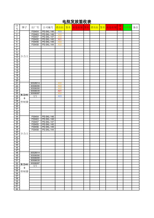
小力士
30528014 30506090 30506095 30506035 30506087 无号
BSD600 控制器
电批发放签收表
序号 牌子
1 2 3 4 5 6 7 8 9 10 11 12 13 14 15 16 17 18 19 20 21 22 23 24 25 26 27 28 29 31 32 33 34 35 36 37 38 39 40 41 42 43 44 45 46 47 48 49 50 51 52 53 54 55 56 57 58 59 60 61 62 63 64
公司编号 借出拉 签名 还仓拉别 签名 借出拉 签名 还仓拉别 签名 在库数 备注
PD-SKL-089 PD-SKL-065 PD-SKL-067 PD-SKL-066 PD-SKL-076 PD-SKL-092 PD-SKL-069 PD-SKL-071 PD-SKL-085 PD-SKL-078 PD-SKL-111 PD-SKL-079 PD-SKL-110 PD-SKL-075 PD-SKL-068 PD-SKL-084 PD-SKL-073 PD-SKL-077 PD-SKL-080 PD-SKL-074 PD-SKL-088 PD-SKL-083 PD-SKL-082 PD-SKL-091 PD-SKL-090 PD-SKL-081 PD-SKL-093 A03 A03 A01 A01 A03 A03 A01 A01 A02 A02 A02 A02 A01 A02 A02 A03 A03 A02 A02 A02 A03 A02 A03 A03 A03 A02 A02
出厂号
J2003033 J2003105 J2003044 J2003035 J2002964 J2003124 J2003175 J2003115 J2003216 J2002959 J2002955 J2002505 J2003202 J2003113 J2003116 J2003039 J2003121 J2003117 J2003954 J2002948 J2003662 J2003103 J2002950 J2003120 J2002952 J2003051 J2003111
Eaton 9155和9355系列UPS的安装说明及UL924安装补充说明说明书

In addition to the standard install guide and manual supplied for the Eaton 9155 and 9355 series UPS. Please review this addendum; it contains a listing of specific changes made to meet all UL924 Emergency Lighting System requirements.IMPORTANT SAFEGUARDSWhen using electrical equipment, basic safety precautions should always be followed including the following:READ AND FOLLOW ALL SAFETY INSTRUCTIONS.-Do not let power supply cords touch hot surfaces.-Do not mount near gas or electric heaters.-Use caution when servicing batteries. If acid is spilled on the skin or eyes, flush acid with fresh water and contact a physician immediately.-Equipment should be mounted in locations and at heights where it will not be subject to tampering by unauthorized personnel.-Use of accessory equipment not recommended by the manufacturer may cause an unsafe condition-Do not use this equipment for other than its intended use.SAVE THESE INSTRUCTIONSATTENTION: These systems are designed and tested as a set and require both the inverter (UPS) and added battery cabinet(s) as listed to supply a minimum 90 minutes of on-battery runtime in the event of a power outage for EMERGENCY EGRESS LIGHTING.These systems are designed for dedicated egress lighting only.These systems have been specifically modified to require mechanical means to shut off or turnto bypass mode (or otherwise disable) as required by Life Safety Codes within the UL924 standard. All modifications done to achieve UL924 listings do not interfere with standard accessories typically available for use with these 8-30KVA Eaton products. Examples include Seismic Kits and Options cabinets.1Part Number 90-016 rev 5 1. This is true for the 20-30 KVA 480 V Models. The UL approved 20-30 KVA 208 V system is used, with anDETAILED 10KVA/7.2KW & 15KVA/9.1KW 277VAC versionsSummary of mechanical changes for inverter and matching Battery Cabinet(s)Shield Guard over any exposed circuit breakers, the DC breaker on the back of each battery cabinet and the 2 breakers on the UPS (one DC breaker and one input breaker). This Shield Guard requires a small tool to disconnect (open) but can be switched on by a finger.Mechanical BATTERY CABLE STRAIN RELIEFs are also added on all 15KVA and below systems to DC Battery connectors which are supplied and are required to be re-installed before system activation is complete.FIGURE 1DC BATTERY BREAKERSHIELD GUARDINSTALLEDBolts added to secure front panel (or Bezel) which otherwise exposes a means of disconnectBOLTSADDEDFIGURE 2SHIELDED BRACKET installed over front panel display buttons which requires a pen tip or other small tool to activate controls.DISPLAYSHIELDCOVERINGBUTTONSFIGURE 3Redesign and relocation of the typical Input/Output configuration of a 9155 series with theisolation transformer option, which is required for 277VAC design. The Input and Output terminal block of the Isolation Transformer is prewired with NO USER ACCESS. In addition the UPS module terminal block is relocated lower on the rear panel and serves as BOTH INPUT and OUTPUTaccess. BOTH ORIGINAL access plates are pre-wired. There is a NEW Input and Output terminal block now centrally located behind a single access panel.9155 Series 277VAC 1P 15KVA Chassis models approved and UL Listed UL924 configurations:10KVA 277VAC 1PH 7.2KW includes (1) BH-8KEL277-100 Controller (UPS) module and (2) BH-EBM96EL-60015KVA 277VAC 1PH 9KW includes (1) BH-10KEL277-100 Controller (UPS) module and (2) BH-EBM96EL-600DETAILED 8KVA/7.2KW, 10KVA/8.5KW & 15KVA/13.1KW 3P 208VAC versionsSummary of mechanical changes for inverter and matching Battery Cabinet(s)Shield Guard over any exposed circuit breakers, the DC breaker on the back of each battery cabinet and the 2 breakers on the UPS (one DC breaker and one input breaker). This Shield Guard requires a small tool to disconnect (open) but can be switched on by a finger.Mechanical BATTERY CABLE STRAIN RELIEFs are also added on all 15KVA and below systems to DC Battery connectors which are supplied and are required to be re-installed before system activation is complete.FIGURE 5DC BATTERY BREAKERSHIELD GUARDINSTALLEDFigure 6 shows the Service Bypass Switch with the handle removed, this is another requirement based on the UL924 Standard in which the handle when installed can place the system off line. The handle ships with the UPS, but should be stored in a secure place and only used during authorized service.FIGURE 6Bolts added to secure front panel (or Bezel) which otherwise exposes a means of disconnectFIGURE 7 BOLTS ADDEDSERVICE BYPASS SWITCH WITH HANDLE REMOVEDSHIELDED BRACKET installed over front panel display buttons which requires a pen tip or other small tool to activate controls.DISPLAYSHIELDCOVERINGBUTTONSFIGURE 89355 Series 208VAC 3P 15KVA Chassis models approved and UL Listed UL924 configurations:8KVA 208VAC 3PH 7.2KW includes (1) BH-8KEL2083P-100 Controller (UPS) module and (1) BH-EBM96EL-60010KVA 208VAC 3PH 8.5KW includes (1) BH-10KEL2083P-100 Controller (UPS) module and (2) BH-EBM96EL-60015KVA 208VAC 3PH 13.1KW includes (1) BH-15KEL2083P-100 Controller (UPS) module and (3) BH-EBM96EL-60020-30KVA Chassis ModelsDETAILED 20KVA/18KW, 30KVA/24KW & 30KVA/27KW 3P 208VAC versions Summary of mechanical changes for inverter and matching Battery Cabinet(s)Modifications include:Shielded bracket over front panel display buttons of which require a pen tip or other small tool to activate. (See FIGURE 9)Front panel has Bolts added (similar to all Extended Battery Cabinets) which otherwise exposes ameans of disconnect via Service Bypass Switch.9355 Series 208VAC 3P 30KVA Chassis current models approved and UL Listed UL924 configurations:20KVA 208VAC 3PH 18KW includes (1) BH-20KEL2083P-100 Controller (UPS) module and(2) BH-EBC72EL-60030KVA 208VAC 3PH 24KW includes (1) BH-30KEL208SF-100 Controller (UPS) module and(2) BH-EBC72EL-60030KVA 208VAC 3PH 27KW includes (1) BH-30KEL2083P-100 Controller (UPS) module and(3) BH-EBC72EL-600DISPLAYSHIELDCOVERINGBUTTONSFIGURE 9。
UL924 应急灯测试项目要求
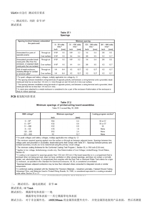
UL924应急灯测试项目要求一:测试项目:间距章节37测试要求PCB板装配间距要求二:测试项目:漏电流测试章节44测试要求; <0.75mA测试部位:裸露带电体表面——地裸露带电导体表面——其它裸露带电体表面测试方法:对于非金属外壳,100X200mm的金属箔放置外壳中,并使金属箔连接到产品表面,然后再测量金属箔到接地导体,金属箔和其它裸露导体到接地导体,以及金属箔到产品裸露表面之间的电流三:测试项目:电池放电测试章节46测试要求:电池电压不小于额定电压的87.5 %。
流明输出不小于的60%测试方法1:温度:产品宣称温度低于20°,测试温度为额定温度低5度,产品宣称额定温度高于30°,测试温度为额定温度高5度,产品宣称温度20-30°,测试温度为25度,2:电池在最大额定负载下放电,放电时间以制造商规定的时间但是不能小于1-1/2 小时,然后测量闭合电路下电池端的电压或者流明输出。
3:充电电池连接到最大额定负载,且允许放电。
产品进行流明输出测量,进入放电后1分钟记录流明值测试项目:输入测试章节48测试方法,额定输入电压和频率下测试要求,如是瓦特,则输入功率不大于额定输入功率的10%,如是安培,则输入电流不大于额定电流的5% PS: 对于带有电池充电器的应急灯,产品的输入测试需要在电池进行放电测试后测量。
(电池在最大额定负载条件下放电24个小时)四:低电压和限能电路的判定章节49测试要求:最大输出电路电压小于30V AC , 42.4 peak 最大电流不超过8A测试时间1min测试方法:输出电路连接一可调电阻负载,(如多组输出,则每组输出单独评估,其它输出开路),从开路到短路调节可调电阻,直到获得最大电流8A 且稳定保持操作1分钟。
如在任何负载条件下无法获得最大电流8A 则,放弃此测试如次级使用了保险丝或类似装置来限制输出电流,保险丝额定值如下49.1表五:限阻抗电路判定测试要求:任何负载下(包括短路),从电路中传输的最大功率小于15W测试时间1min测试方法:输出电路连接一可调电阻负载,(如多组输出,则每组输出单独评估,其它输出开路),从开路到短路调节可调电阻,直到获得最大输出功率15W持操作1分钟。
SP-801-2型通用压力变送器说明书
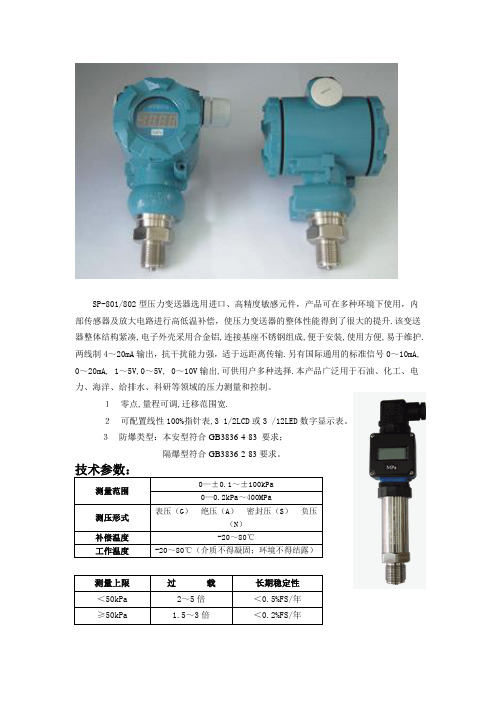
SP-801/802型压力变送器选用进口、高精度敏感元件,产品可在多种环境下使用,内部传感器及放大电路进行高低温补偿,使压力变送器的整体性能得到了很大的提升.该变送器整体结构紧凑,电子外壳采用合金铝,连接基座不锈钢组成,便于安装,使用方便,易于维护.两线制4~20mA输出,抗干扰能力强,适于远距离传输.另有国际通用的标准信号0~10mA, 0~20mA, 1~5V,0~5V, 0~10V输出,可供用户多种选择.本产品广泛用于石油、化工、电力、海洋、给排水、科研等领域的压力测量和控制。
1零点,量程可调,迁移范围宽.2可配置线性100%指针表,3 1/2LCD或3 /12LED数字显示表。
3防爆类型:本安型符合GB3836·4-83 要求;隔爆型符合GB3836·2-83要求。
注:具体参数可根据客户要求定制或见本产品出厂说明书.SP-801选型表注:型号,量程范围,测压形式,输出信号,接口尺寸,引线方式,供电电源为必选区。
现场显示,防爆类型为任选区。
负载:与供电电源有关,负载阻抗R与电源电压V的关系式为R≤50(V—12)Ω。
(工厂一般用24VDC供电,负载250Ω)注:带数显表头时,负载能力有所降低SP-802选型表注:型号,量程范围,测压形式,输出信号,接口尺寸,引线方式,供电电源为必选区。
现场显示,防爆类型为任选区。
负载:与供电电源有关,负载阻抗R与电源电压V的关系式为R≤50(V—12)Ω。
(工厂一般用24VDC供电,负载250Ω)注:带数显表头时,负载能力有所降低接线方式电路IC24VZS SP-801结构尺寸:·电子外壳:合金铝 ·主体结构:不锈钢 ·重 量:约1.0kg ·涂 层:塑料喷涂现场连线:Z---调零电位器 S---调量程电位器SP-802简易型结构尺寸主体结构:不锈钢重 量:约1.0kg电气连接注意:如无计量设备,请勿调节量程(S)电位器。
国家仪器 NI 9246 设备参数说明说明书
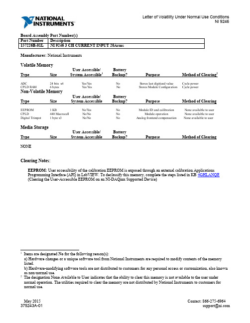
Manufacturer: National InstrumentsVolatile MemoryUser Accessible/ BatteryType Size System Accessible1Backup? Purpose Method of Clearing2ADC 24 bits x4 Yes/Yes No Stores last digitized value Cycle powerCPLD RAM 6 bytes Yes/Yes No Stores Module Configuration Cycle powerNon-Volatile MemoryUser Accessible/ BatteryType Size System Accessible Backup? Purpose Method of Clearing EEPROM 1 KB No/Yes No Module ID and calibration None available to userCPLD 440 Macrocell No/No No Module operation None available to userDigital Trimpot 1 byte x3 No/No No Analog frontend compensation None available to user Media StorageUser Accessible/ BatteryType Size System Accessible Backup? Purpose Method of Clearing NONEClearing Notes:EEPROM: User accessibility of the calibration EEPROM is exposed through an external calibration Applications Programming Interface (API) in LabVIEW. To declassify this memory, complete the steps listed in KB 4GHLANQE (Clearing the User-Accessible EEPROM on an NI-DAQmx Supported Device)1 Items are designated No for the following reason(s):a) Hardware changes or a unique software tool from National Instruments are required to modify contents of the memory listed.b) Hardware-modifying software tools are not distributed to customers for any personal access or customization, also known as non-normal use.2 The designation None Available to User indicates that the ability to clear this memory is not available to the user under normal operation. The utilities required to clear the memory are not distributed by National Instruments to customers for normal use.Terms and DefinitionsUser Accessible Allows the user to directly write or modify the contents of the memory during normal instrument operation.System Accessible Does not allow the user to access or modify the memory during normal instrument operation. However, system accessible memory may be accessed or modified by background processes. This can be something that is not deliberate by the user and can be a background driver implementation, such as storing application information in RAM to increase speed of use.Cycle Power The process of completely removing power from the device and its components. This process includes a complete shutdown of the PC and/or chassis containing the device; a reboot is not sufficient for the completion of this process. Volatile Memory Requires power to maintain the stored information. When power is removed from this memory, its contents are lost.Non-Volatile Retains its contents when power is removed. This type of memory typically contains calibration or chip configuration information, such as power up states.。
小学_六年级_口算_强化练习题
用时:分秒用时:分 秒测试时间:年月日测试时间:年月日小学数学六年级下册口算训练(1) 训练(2)小学数学六年级下册口算小学数学六年级下册口算训练(3)小学数学六年级下册口算训练(4)日小学数学六年级下册口算训练(5) 小学数学六年级下册口算训练(6)用时:分秒用时:分秒测试时间:年月日测试时间:年月360防900=0.3+0.7二 320?80=1-0.64=17 7—+—= 18 180.58-0.5=11_3= 16165.7+4.5=35-+—= 8810-0・1二9 _7= 10 100.6X100=6|5+ 6|5 I I7.3三1000=1142121=7200三2524=17 7—+—= 18 188X(40+20)=11_3= 1616422(90230)=8_2= 1515182(2424)=5_1= 8810.5-1.5-3.5=71 —+—= 12124.6+2.3+7.7=00I 3+ 0015 I I145+78+255=9 _7= 10 10125X32=6|5+ 6|5 I I156-64-36=1.5X 0.2=4X250= 1.5X0.5=0X518=3X 2= 8510X76=9・8*98=36X10= 9.8*100=15X6=2224X3=82・5—3.25=5X18=1.5X 0.2=26X4=1+1=23403X15=1+丄=2467X18=1-20%=180X50=13 1+—=440424=1+60%=78+32=2X 2=280+60=0.25+0.75=0.8+0.2= 713X (2+13)=720290=1.5X 5=7)用时:分秒用时:分 秒测试时间: 年月日测试时间:年月日训练(8)4X 2=1.25X8—0.1X0.02=3.7+7.6—1丄3_—•—— 25910寺70=4.220.1=100_1・01=2+1- 3623—+—=1515100X0.35=18.2+0.28=小学数学六年级下册口算训练(9)训练(10)小学数学六年级下册口算用时:分秒秒用时:分小学数学六年级下册口算训练(11)小学数学六年级下册口算训练(12)用时:分秒用时:分秒测试时间:年月日测试时间:年月日小学数学六年级下册口算训练(13)小学数学六年级下册口算训练(14)用时:分秒用时:分秒测试时间:年月日测试时间:年月小学数学六年级下册口算训练(17)小学数学六年级下册口算训练(18)用时:分秒用时:分秒测试时间:年月日测试时间:年月日小学数学六年级下册口算训练(19)小学数学六年级下册口算训练(20)用时:分秒用时:分秒测试时间:年月日测试时间:年月日小学数学六年级下册口算训练(21)小学数学六年级下册口算训练(22)用时:分秒用时:分秒测试时间:年月日测试时间:年。
双法兰差压变送器技术规格书及数据表(6台)(1)

兖矿鲁南化工有限公司技术协议书双法兰差压变送器编制:审核:审批:卖方:上海盛凯隆自动化仪表有限公司买方:兖矿鲁南化工有限公司二○一七年三月1.总则1.1 设备名称:双法兰差压变送器1.2 本技术规格书提出的是最低限度的要求,并未对一切细节做出规定,也未充分引述有关标准和规范的条文,卖方应保证提供符合本技术规格书和有关最新工业标准的产品。
1.3 所招产品为双法兰变送器,卖方产品必须完全满足水煤浆加压气化工艺的特殊工况。
2. 产品描述2.1本规格书要求购买变送器共6台。
2.2本变送器要求为进口品牌的产品。
品牌限定为罗斯蒙特3051系列变送器。
2.3针对此变送器的重要性及其较苛刻的工况,卖方均要严格按本技术要求及数据表的要求进行配置。
3.设计依据3.1此变送器的设计和选型应严格按照协议书的要求,以及买方提出的任何其它技术要求。
3.2环境状况:年平均气温:13.7℃;极端最高气温:40.4℃;极端最低气温:-21.8℃;年平均相对湿度:69%;地区大气压:平均1079mbar;3.3仪表及所配电气附件防护要求:防护等级:IP65防爆等级:ExdII CT44.应用标准仪表安装手册API RP550仪器仪表包装运输技术条件ZBY003-84工业仪表模拟信号ISA S50.1爆炸性环境用防爆电气设备IEC 60079—1998、GB3886仪表防护IEC 529、GB4208-2000法兰标准见数据表铭牌和印记MSS-SP-255.技术要求5.1 卖方所供差压变送器及附件产品必须是全新产品,整体集成供货。
5.2 卖方所供产品必须满足后面数据表的要求。
5.3 输出两线制4-20mA DC信号,具有HART通讯功能,能被普通HART375、475手操器支持。
5.4 仪表应带有现场液晶指示功能。
5.5 隔膜密封变送器,要求测量膜片及毛细管耐真空设计。
5.6 特殊介质场合,变送器的测量元件材质应保证变送器的使用性能。
乙烯基三(2-甲氧基乙氧基)硅烷

乙烯基三(2-甲氧基乙氧基)硅烷下载温馨提示:该文档是我店铺精心编制而成,希望大家下载以后,能够帮助大家解决实际的问题。
文档下载后可定制随意修改,请根据实际需要进行相应的调整和使用,谢谢!并且,本店铺为大家提供各种各样类型的实用资料,如教育随笔、日记赏析、句子摘抄、古诗大全、经典美文、话题作文、工作总结、词语解析、文案摘录、其他资料等等,如想了解不同资料格式和写法,敬请关注!Download tips: This document is carefully compiled by the editor. I hope that after you download them, they can help you solve practical problems. The document can be customized and modified after downloading, please adjust and use it according to actual needs, thank you!In addition, our shop provides you with various types of practical materials, such as educational essays, diary appreciation, sentence excerpts, ancient poems, classic articles, topic composition, work summary, word parsing, copy excerpts, other materials and so on, want to know different data formats and writing methods, please pay attention!化学品乙烯基三(2-甲氧基乙氧基)硅烷(VTMOS)是一种广泛应用于涂料、纤维、橡胶、塑料等领域的重要有机硅化合物。
924AIY中文资料
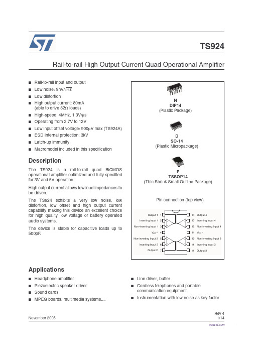
Rev 4November 20051/14TS924Rail-to-rail High Output Current Quad Operational Amplifier■Rail-to-rail input and output ■Low noise: 9nV/√Hz ■Low distortion■High output current: 80mA (able to drive 32Ω loads)■High-speed: 4MHz, 1.3V/µs ■Operating from 2.7V to 12V■Low input offset voltage: 900µV max (TS924A)■ESD Internal protection: 3kV ■Latch-up immunity■Macromodel included in this specificationDescriptionThe TS924 is a rail-to-rail quad BiCMOS operational amplifier optimized and fully specified for 3V and 5V operation.High output current allows low load impedances to be driven.The TS924 exhibits a very low noise, low distortion, low offset and high output current capability making this device an excellent choice for high quality, low voltage or battery operated audio systems.The device is stable for capacitive loads up to 500pF .Applications■Headphone amplifier ■Piezoelectric speaker driver ■Sound cards■MPEG boards, multimedia systems,...■Line driver, buffer■Cordless telephones and portable communication equipment■Instrumentation with low noise as key factorTS9242/14Order CodesPart Number Temperature RangePackagePackagingMarking TS924IN -40°C, +125°C DIP14T ubeTS924IN TS924AIN TS924AIN TS924ID/IDT SO-14T ube or T ape & Reel924I TS924AID/AIDT 924AI TS924IPT TSSOP14(Thin Shrink Outline Package)Tape & Reel924I TS924AIPT 924AI TS924IYD/IYDT SO-14 (automotive grade level)T ube or T ape & Reel924IY TS924AIYD/AIYDT 924AIY TS924IYPT TSSOP14 (automotive grade level)Tape & Reel924IY TS924IAIYPT924AIYTS924Absolute Maximum Ratings3/141 Absolute Maximum RatingsTable 1.Key parameters and their absolute maximum ratingsSymbol ParameterValue Unit V CC Supply voltage (1)1.All voltages values, except differential voltage are with respect to network ground terminal.14V Vid Differential Input Voltage (2)2.Differential voltages are the non-inverting input terminal with respect to the inverting input terminal. If Vid > ±1V ,the maximum input current must not exceed ±1mA. In this case (Vid > ±1V) an input serie resistor must be added to limit input current.±1V V i Input Voltage (3)3.Do not exceed 14V.V DD -0.3 to V CC +0.3V T stg Storage T emperature-65 to +150°C T jMaximum Junction Temperature 150°CR thjaThermal Resistance Junction to Ambient DIP14103°C/W SO1466TSSOP14100ESDHBM: Human Body Model (4)4.Human body model, 100pF discharged through a 1.5k Ω resistor into pin of device.3kV MM: Machine Model (5)5.Machine model ESD, a 200pF cap is charged to the specified voltage, then discharged directly into the IC withno external series resistor (internal resistor < 5Ω), into pin to pin of device.100V CDM: Charged Device Model 1kV Output Short Circuit Duration see note (6)6.There is no short-circuit protection inside the device: short-circuits from the output to V cc can cause excessiveheating. The maximum output current is approximately 80mA, independent of the magnitude of V cc . Destructive dissipation can result from simultaneous short-circuits on all amplifiers.Latch-up Immunity200mA Soldering T emperature (10sec), leaded version 250°C Soldering T emperature (10sec), unleaded version260°C Table 2.Operating conditionsSymbol ParameterValue Unit V CC Supply voltage2.7 to 12V V icm Common Mode Input Voltage Range V DD -0.2 to V CC +0.2V T operOperating Free Air T emperature Range-40 to +125°CCharacteristics2 ElectricalTable 3.V CC = +3V, V DD = 0V, V icm = V CC/2, T amb = 25°C, R L connected to V CC/2 (unless4/14Table 4.V CC = +5V, V DD = 0V, V icm = V CC/2, T amb = 25°C, R L connected to V CC/2 (unless5/14Figure 1.Output short circuit current vs.Figure 2.Output short circuit current vs.Figure 3.Voltage gain and phase vs.6/147/14Macromodel TS9248/143 Macromodel3.1Important note concerning this macromodelPlease consider following remarks before using this macromodel.●All models are a trade-off between accuracy and complexity (i.e. simulation time).●Macromodels are not a substitute to breadboarding; rather, they confirm the validity of a design approach and help to select surrounding component values.●A macromodel emulates the NOMINAL performance of a TYPICAL device withinSPECIFIED OPERATING CONDITIONS (i.e. temperature, supply voltage, etc.). Thus the macromodel is often not as exhaustive as the datasheet, its goal is to illustrate the main parameters of the product.●Data issued from macromodels used outside of its specified conditions (Vcc, T emperature, etc.) or even worse: outside of the device operating conditions (Vcc, Vicm, etc.) are not reliable in any way.In Section 3.3, the electrical characteristics resulting from the use of these macromodels are presented.3.2 Electrical characteristics from macromodelizationTable 5.Electrical characteristics resulting from macromodel simulation at V CC = 3V, V DD = 0V, R L , C L connected to V CC/2, T amb = 25°C (unless otherwise specified)Symbol ConditionsValue Unit V io 0mV A vd R L = 10k Ω200V/mV I CC No load, per operator1.2mA V icm -0.2 to 3.2V V OH R L = 10k Ω2.95V V OL R L = 10k Ω25mV I sink V O = 3V 80mA I source V O = 0V 80mA GBP R L = 600k Ω4MHz SR R L = 10k Ω, C L = 100pF 1V/µs φmR L = 600k Ω68DegreesTS924Macromodel9/143.3 Macromodel code** Standard Linear Ics Macromodels, 1996.** CONNECTIONS:* 1 INVERTING INPUT* 2 NON-INVERTING INPUT * 3 OUTPUT* 4 POSITIVE POWER SUPPLY * 5 NEGATIVE POWER SUPPLY.SUBCKT TS92X 1 2 3 4 5 *.MODEL MDTH D IS=1E-8 KF=2.664234E-16 CJO=10F ** INPUT STAGECIP 2 5 1.000000E-12CIN 1 5 1.000000E-12EIP 10 5 2 5 1EIN 16 5 1 5 1RIP 10 11 8.125000E+00RIN 15 16 8.125000E+00RIS 11 15 2.238465E+02DIP 11 12 MDTH 400E-12DIN 15 14 MDTH 400E-12VOFP 12 13 DC 153.5u VOFN 13 14 DC 0IPOL 13 5 3.200000E-05CPS 11 15 1e-9DINN 17 13 MDTH 400E-12VIN 17 5 -0.100000e+00DINR 15 18 MDTH 400E-12VIP 4 18 0.400000E+00FCP 4 5 VOFP 1.865000E+02FCN 5 4 VOFN 1.865000E+02FIBP 2 5 VOFP 6.250000E-03FIBN 5 1 VOFN 6.250000E-03* GM1 STAGE ***************FGM1P 119 5 VOFP 1.1FGM1N 119 5 VOFN 1.1RAP 119 4 2.6E+06RAN 119 5 2.6E+06* GM2 STAGE *************** G2P 19 5 119 5 1.92E-02G2N 19 5 119 4 1.92E-02R2P 19 4 1E+07R2N 19 5 1E+07**************************VINT1 500 0 5GCONVP 500 501 119 4 19.38 VP 501 0 0GCONVN 500 502 119 5 19.38 VN 502 0 0Macromodel TS92410/14********* orientation isink isource ******* VINT2 503 0 5FCOPY 503 504 VOUT 1DCOPYP 504 505 MDTH 400E-9VCOPYP 505 0 0DCOPYN 506 504 MDTH 400E-9VCOPYN 0 506 0***************************F2PP 19 5 poly(2) VCOPYP VP 0 0 0 0 0.5F2PN 19 5 poly(2) VCOPYP VN 0 0 0 0 0.5F2NP 19 5 poly(2) VCOPYN VP 0 0 0 0 1.75F2NN 19 5 poly(2) VCOPYN VN 0 0 0 0 1.75* COMPENSATION ************CC 19 119 25p* OUTPUT ***********DOPM 19 22 MDTH 400E-12DONM 21 19 MDTH 400E-12HOPM 22 28 VOUT 6.250000E+02VIPM 28 4 5.000000E+01HONM 21 27 VOUT 6.250000E+02VINM 5 27 5.000000E+01VOUT 3 23 0ROUT 23 19 6COUT 3 5 1.300000E-10DOP 19 25 MDTH 400E-12VOP 4 25 1.052DON 24 19 MDTH 400E-12VON 24 5 1.052.ENDS ;TS92X4 Package Mechanical DataIn order to meet environmental requirements, ST offers these devices in ECOPACK® packages.These packages have a Lead-free second level interconnect. The category of second levelinterconnect is marked on the package and on the inner box label, in compliance with JEDECStandard JESD97. The maximum ratings related to soldering conditions are also marked onthe inner box label. ECOPACK is an ST trademark. ECOPACK specifications are available at:.11/1412/1413/14Revision History TS92414/145 Revision HistoryDate RevisionChangesMay 20011First ReleaseMay 20052Modifications on AMR Table 1 on page 3 (explanation of Vid and Vilimits, ESD MM and CDM values added, Rthja added)July 20053PP AP references inserted in the datasheet see Table on page 2.Nov. 20054–Package mechanical data modified–TS924IYPT/TS924AYIPT PPAP reference inserted in Table on page 2.–Macromodel modifiedInformation furnished is believed to be accurate and reliable. However, STMicroelectronics assumes no responsibility for the consequences of use of such information nor for any infringement of patents or other rights of third parties which may result from its use. No license is granted by implication or otherwise under any patent or patent rights of STMicroelectronics. Specifications mentioned in this publication are subject to change without notice. This publication supersedes and replaces all information previously supplied. STMicroelectronics products are not authorized for use as critical components in life support devices or systems without express written approval of STMicroelectronics.The ST logo is a registered trademark of STMicroelectronics.All other names are the property of their respective owners© 2005 STMicroelectronics - All rights reservedSTMicroelectronics group of companiesAustralia - Belgium - Brazil - Canada - China - Czech Republic - Finland - France - Germany - Hong Kong - India - Israel - Italy - Japan -Malaysia - Malta - Morocco - Singapore - Spain - Sweden - Switzerland - United Kingdom - United States of America。
原料性能参数表
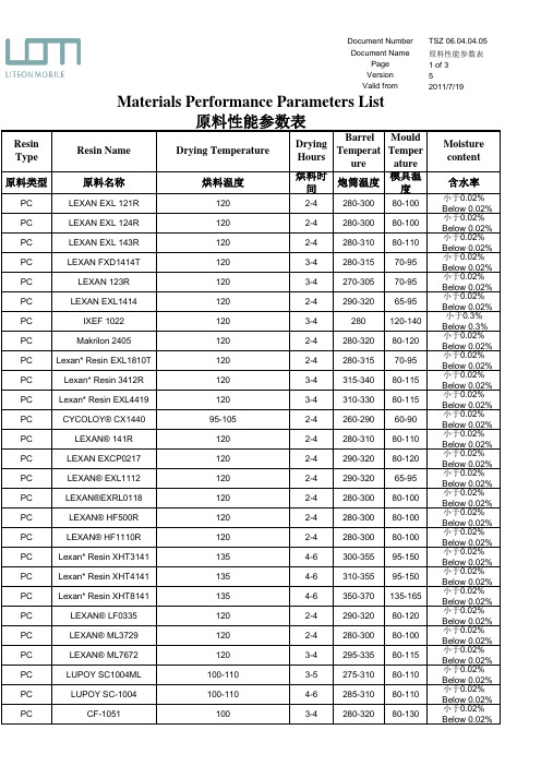
TSZ 06.04.04.05原料性能参数表1 of 352011-7-19Resin Type Resin Name Drying TemperatureDryingHoursBarrel Temperat ure MouldTemperatureMoisturecontent 原料类型原料名称烘料温度烘料时间炮筒温度模具温度含水率PC LEXAN EXL 121R 1202-4280-30080-100小于0.02% Below 0.02%PC LEXAN EXL 124R 1202-4280-30080-100小于0.02% Below 0.02%PC LEXAN EXL 143R 1202-4280-31080-110小于0.02% Below 0.02%PC LEXAN FXD1414T 1203-4280-31570-95小于0.02% Below 0.02%PC LEXAN 123R 1203-4270-30570-95小于0.02% Below 0.02%PC LEXAN EXL14141202-4290-32065-95小于0.02% Below 0.02%PC IXEF 10221203-4280120-140小于0.3% Below 0.3%PC Makrilon 24051202-4280-32080-120小于0.02% Below 0.02%PC Lexan* Resin EXL1810T 1202-4280-31570-95小于0.02% Below 0.02%PC Lexan* Resin 3412R 1203-4315-34080-115小于0.02% Below 0.02%PC Lexan* Resin EXL44191203-4310-33080-115小于0.02% Below 0.02%PC CYCOLOY® CX144095-1052-4260-29060-90小于0.02% Below 0.02%PC LEXAN® 141R 1202-4280-31080-110小于0.02% Below 0.02%PC LEXAN EXCP02171202-4290-32080-120小于0.02% Below 0.02%PC LEXAN® EXL11121202-4290-32065-95小于0.02% Below 0.02%PC LEXAN®EXRL01181202-4280-30080-100小于0.02% Below 0.02%PC LEXAN® HF500R 1202-4280-30080-100小于0.02% Below 0.02%PC LEXAN® HF1110R 1202-4280-30080-100小于0.02% Below 0.02%PC Lexan* Resin XHT31411354-6300-35595-150小于0.02% Below 0.02%PC Lexan* Resin XHT41411354-6310-35595-150小于0.02% Below 0.02%PC Lexan* Resin XHT81411354-6350-370135-165小于0.02% Below 0.02%PC LEXAN® LF03351202-4290-32080-120小于0.02% Below 0.02%PC LEXAN® ML37291202-4280-30080-100小于0.02% Below 0.02%PC LEXAN® ML76721203-4295-33580-115小于0.02% Below 0.02%PC LUPOY SC1004ML 100-1103-5275-31080-110小于0.02% Below 0.02%PC LUPOY SC-1004100-1104-6285-31080-110小于0.02% Below 0.02%PCCF-10511003-4280-32080-130小于0.02% Below 0.02%Materials Performance Parameters List原料性能参数表Document Number Document NamePage Version Valid from。
BPS4000产品规格说明书

1 2 3 4 5 6 7 8 9Specification StatusChange Made atBPS4000 revRev revDate Attachments Org Title supersededBy specialNotes latestSupersedingDoc reviewBy 160-006AM040322BHTI Alternate Materials List M&P 299-947-100-690115BHTI Procurement Specification for Epoxy Adhesive, Heat Resistant M&P 299-947-320-820507BHTIAdhesive Film and Primer System, Intermedite Cure Temperature (260-290º F) ServiceTemerature 67-225º F)M&P 68A900000G011101BAC Finish Spec:F-15M&P 74A900000E990308BAC Finish Specification for F18 Aircraft M&P 74A900004L010501BAC Ctrl:Fract Crit Parts, F-18M&P 74A901001F981208BAC Std Finish Codes:F-18 A\C M&P 901-947-002CA D950510BHTI Finish Specification for the V-22 Aircraft (Bell Boeing) Model 901) EMD Aircraft M&P10 11 12 13 14 15 16 17 18 19 20 21 22 23 24 25 26A-A-208B951120Notice 2 Notice 3FED Ink, Marking, Stencil, Opaque M&P A-A-2962Cancelled no s/s spec A980810canc notice 2-060106FED Commercial Item Description Enamel, Alkyd, Exterior, Solvent Based, Low Voc ok to use canc spec M&P A-A-3097BK-970506Notice 3FEDCommercial Item Description Adhesives, Cyanoacrylate, Rapid Room Temperature-Curing,SolventlessM&P A-A-3165CA A071116Notice 2FED Lacquer, Gloss, for A/C Use M&P A-A-52080B980523Notice 1FED Tape, Lacing, and Tying, Nylon M&P A-A-52081B980523FED Tape, Lacing, and Tying, Polyester M&P A-A-52082CE C070904Notice 1FED Tape, Lacing and Tying, TFE-Fluorocarbon M&P A-A-52083BJ C040223FED Tape, Lacing, and Tying, Glass M&P A-A-52084B980523Notice 1FED Tape, Lacing and Tying, Aramid M&P A-A-55829-970204Notice 1DLA Acetic Acid, Glacial, Technical M&P A-A-56032CN D030521Notice 1FED Commercial Item Description (CIDS) Ink, Marking, Epoxy Base M&P A-A-59126-970926FED Terminals, Feedthru (Insulated) and Terminals, Stud (Insulated and Noninsulated)ENG A-A-59132CR A100607Validation Notice 1DLA Amyl Acetate, Technical M&P A-A-59135CR-971028FED Commercial Item Description Packaging Material, Sheet M&P A-A-59136CR-971028FED Cushioning Material, Packaging, Closed Cell Foam Plank M&P A-A-59178CL A041012USGOVT Nipple, Electrical Terminal ENG A-A-59503CG B081020FED Commercial Item Description Nitrogen, Technical M&P A A59551Wire Electrical Copper(Uninsulated)27 28 29 30 31 32 33 34 35 36 37 38 39 40 41 42 43 44A-A-59551CP A091022USGOVT Wire, Electrical, Copper (Uninsulated) M&P A-A-59569CK C090122DLA Qualification Sampling and Testing of Steels for Transverse Tensile Properties ENG A-A-59588BK A050707FED Commercial Item Description Rubber, Silicone M&P A-A-59877CT-100909FED Comemrcial Item Description Insulating Compound, Electrical, Embedding M&P AIR4127CG - 071101SAE Steel: Chemical Composition and Hardenability M&P AISI-1010Unavailable-AISI Low Carb Stl Unavailable M&P AISI-50100Unavailable-AISI Bearing Stl Unavailable M&P AISI-52100Unavailable-AISI Bearing Stl Unavailable M&P AISI-B-1112Unavailable-AISI Low Carb Free Mach Stl Unavailable M&P AISI-C-1212Unavailable-AISI Matl Spec, Stl Unavailable M&P AISI-C-1213Unavailable-AISI Low Carb Free Mach Stl Unavailable M&P AISI-C-1214Unavailable-AISI Matl Spec, Stl Unavailable M&P AMS 2175CR A100601SAE Castings, Classification and Inspection of M&PAMS 2201Cancelled CN Can940901SAETolerances Aluminum and Aluminum Alloy Bar, Rod, Wire, and Forging Stock Rolled or Cold-FinishedANSI H35.2M&PAMS 2221G060201SAE Tolerances, Copper and Copper Alloy Bars and Rods M&P AMS 2222BG J060201SAE Tolerances, Copper and Copper Alloy Sheet, Strip, and Plate M&P AMS 2223BF H060201SAE Tolerances Copper and Copper Alloy Seamless Tubing M&P AMS 2224G060201SAE Tolerances Copper and Copper Alloy Wire M&P AMS2241Tolerances,Corrosion and Heat-Resistant Steel,Iron Alloy,Titanium,and Titanium Alloy Bars and45 46 47 4849 50 51 52 53 54 55 56 57 58AMS 2241CN R070701SAETolerances, Corrosion and Heat Resistant Steel, Iron Alloy, Titanium, and Titanium Alloy Bars andWireM&P AMS 2242CC G080604SAETolerances Corrosion and Heat Resistant Steel, Iron Alloy, Titanium and Titanium Alloy Sheet,Strip and PlateM&P AMS 2243BJ H060501SAE Tolerances Corrosion and Heat-Resistant Steel Tubing M&P AMS 2248CN F060501SAEChemical Check Analysis Limits Corrosion and Heat-Resistant Steels and Alloys, Maraging andother Highly-Alloyed Steels, and Iron AlloysM&PAMS 2249CN G090701SAEChemical Check Analysis Limits Titanium and Titanium AlloysM&PAMS 2259CN E071201SAE Chemical Check Analysis Limits Wrought Low-Alloy and Carbon Steels M&P AMS 2269CN F060501SAE Chemical Check Analysis Limits Nickel, Nickel Alloys, and Cobalt Alloys M&P AMS 2300BF K031001SAE Steel Cleanliness, Premium Aircraft-Quality Magnetic Particle Inspection Procedure M&P AMS 2301CT K100801SAE Steel Cleanliness, Aircraft Quality Magnetic Particle Inspection Procedure M&P AMS 2303CT F100801SAESteel Cleanliness, Aircraft Quality, Martensitic Corrosion Resistant Steels Magnetic ParticleInspection ProcedureM&P AMS 2304CN A060301SAE Steel Cleanliness, Special Aircraft-Quality Magnetic Particle Inspection Procedure M&P AMS 2310BE F060201SAE Qualification Sampling and Testing of Steels for Transverse Tensile Properties M&P AMS 2315CN F080101SAE Determination of Delta Ferrite Content M&PAMS 2350Cancelled no s/s spec CN BA891001SAEStandards and Test Methodsok to use canc spec M&P1Specification Status Change Made atBPS4000 revRev revDate Attachments Org Title supersededBy specialNotes latestSupersedingDoc reviewBy59 60 61 62 63 64AMS 2355CN J090701SAEQuality Assurance Sampling and Testing Aluminum Alloys and Magnesium Alloy WroughtProducts (Except Forging Stock), and Rolled, Forged, or Flash Welding RingsM&P AMS 2360CN D070701SAE Room Temperature Tensile Properties of Castings M&P AMS 2370CN J071101SAEQuality Assurance Sampling and Testing Carbon and Low-Alloy Steel Wrought Products andForging StockM&P AMS 2371CN H071101SAEQuality Assurance Sampling and Testing Corrosion and Heat-Resistant Steels and Alloys WroughtProducts and Forging StockM&P AMS 2372CN E070601SAE Quality Assurance Sampling and Testing Carbon and Low-Alloy Steel Forgings M&P AMS 2375CN D070601SAE Control of Forgings Requiring First Article Approval M&PA l d C t l f P i Q lit Tit i All65 66 67 68 69 70 71 72 73 74 75 76 77 78 79 80 81 82AMS 2380CN F080601SAE Approval and Control of Premium-Quality Titanium Alloys M&P AMS 2400BV W070701SAE Plating, Cadmium M&P AMS 2401CN H071101SAE Plating, Cadmium Low Hydrogen Content Deposit M&P AMS 2403BM L041001SAE Plating, Nickel General Purpose M&P AMS 2404CH F081201SAE Plating, Electroless Nickel M&P AMS 2405Noncurrent CN C841010SAE Electroless Nickel Plate, Low Phosphorous M&P AMS 2406BV L070501SAE Plating, Chromium Hard Deposit M&P AMS 2408CF J081101SAE Plating, Tin M&P AMS 2410CR K100401SAE Plating, Silver Nickel Strike, High Bake M&P AMS 2411CB G080201SAE Plating, Silver for High Temperature Applications M&P AMS 2412CN J091201SAE Plating, Silver Copper Strike, Low Bake M&P AMS 2416K040301SAE Plating, Nickel-Cadmium Diffused M&P AMS 2417G040701SAE Plating, Zinc-Nickel Alloy M&P AMS 2418G060101SAE Plating, Copper M&P AMS 2419BM C030501SAE Plating, Cadmium-Titanium M&P AMS 2420D021201SAE Plating of Aluminum for Solderability Zinc Immersion Pre-Treatment Process M&PAMS 2423**See special notes CE D020401SAE Plating, Nickel Hard DepositContinue to use AMS-QQ-N-290 for Class2 NickelM&PAMS 2424CR F100401SAE NI Plate, Low Stressed Deposit M&P AMS2426D Coating Cadmium Vacuum Deposition83 84 85 86 87 88 89 90 91 92 93 94AMS 2426BT020901SAE Coating, Cadmium Vacuum Deposition M&P AMS 2429C011101SAE Bronze Plate Masking M&P AMS 2430CN R100101SAE Shot Peening, Automatic M&P AMS 2433C041001SAE Plating, Nickel-Thallium-Boron or Nickel-Boron M&P AMS 2434CN C060501SAE Plating, Tin-Zinc Alloy M&P AMS 2435Noncurrent CN G070601SAE Coating, Tungsten Carbide-Cobalt Coating, Detonation Process M&P AMS 2437BN C710111SAE Coating, Plasma Spray Deposition M&P AMS 2438CL D090701SAE Plating, Chromium Thin, Hard, Dense Deposit M&P AMS 2444BM A001201SAE Coating, Titanium Nitride Physical Vapor Deposition M&P AMS 2451BN B060501SAE Plating, Brush General Requirements M&PAMS 2460See special notes CA-070701SAE Plating, ChromiumIf dwg requires chrome plate per AMS-QQ-C-320 then stress relief and embritlmnt(emb) bake relief per BPS4620. If dwg req'schrome plate per AMS 2460 then stressrelief and bake relief per AMS 2460 unlessthe dwg specifically req's BPS 4620M&PAMS 2468Cancelled CN G981001SAE Hard Anodic Coating Treatment of Aluminum Alloys AMS 2469M&P AMS 2469CG H080701SAEHard Anodic Coating Treatment of Aluminum and Aluminum Alloys Processing and PerformanceRequirementsM&P95 96 97 98 99 100 101 102 103 104 105 106 107 108 109 110 111qAMS 2470CN M070401SAE Anodic Treatment of Aluminum Alloys Chromic Acid Process M&P AMS 2471CN G081201SAE Anodic Treatment of Aluminum Alloys Sulfuric Acid Process, Undyed Coating M&P AMS 2481CP J100201SAE Phosphate Treatment Antichafing M&PAMS 2482CN D100101SAEHard Anodic Coating on Aluminum Alloys Polytetrafluoroethylene (PTFE)-Impregnated orCodepositedM&PAMS 2485BY K080101SAE Coating, Black Oxide M&P AMS 2486CR E100501SAE Conversion Coating of Titanium Alloys Fluoride-Phosphate Type M&P AMS 2487CN A000301SAE Anodic Treatment of Titanium and Titanium Alloys Solution pH 12.4 Maximum M&P AMS 2488D000606SAE Anodic Tr:Ti,Ti Alys M&P AMS 2515BM E900101SAE Polytetrafluoroethylene (PTFE) Resin Coating Low Build, 370 to 400 °C (698 to 752 °F) Fusion M&P AMS 2516BM D900101SAE Polytetrafluoroethylene (PTFE) Resin Coating High Build, 370 to 400 °C (698 to 752 °F) Fusion M&P AMS 2525C030401SAE Graphite Coating, Thin Lubricating Film Impingement Applied M&P AMS 2526BW C071001SAE Molybdenum Disulfide Coating, Thin Lubricating Film Impingement Applied M&P AMS 2615BM F060901SAE Pressure Testing Hydraulic Pressure as Specified M&P AMS 2630CR C100101SAE Inspection, Ultrasonic Product Over 0.5 Inch (12.7 mm) Thick M&P AMS 2631CN C090701SAE Ultrasonic Inspection Titanium and Titanium Alloy Bar and Billet M&P AMS 2632BN A950301SAEInspection, Ultrasonic, Of Thin Materials 0.50 Inch (12.7 mm) and Under in Cross-SectionalThicknessM&P1Specification Status Change Made atBPS4000 revRev revDate Attachments Org Title supersededBy specialNotes latestSupersedingDoc reviewBy112 113 114 115 116 117 118 119 120AMS 2635Cancelled Can810701SAE Radiographic Insp ASTM E1742M&P AMS 2640Cancelled CH Can960401SAE Magnetic Particle Inspection ASTM E1444M&P AMS 2645Cancelled CH Can950201SAE Fluorescent Penetrant Inspection ASTM E1417M&P AMS 2649CA C080101SAE Etch Inspection of High Strength Steel Parts M&P AMS 2658CN C091001SAE Hardness and Conductivity Inspection of Wrought Aluminum Alloy Parts M&P AMS 2664CH F950701SAE Brazing, Silver For Use Up to 800 °F (427 °C)M&P AMS 2665G030101SAE Brazing, Silver for Use up to 400 °F (204 °C)M&P AMS 2666Cancelled Can840101SAE Ag Braz,High Temp AMS 2664M&P AMS 2670BK J060601SAE Brazing, Copper M&P121 122 123 124 125 126 127 128 129 130 131 132 133 134135AMS 2671Cancelled CH Can920101SAE Copper Brazing Corrosion and Heat Resistant Steels and Alloys AMS 2670M&P AMS 2672BM F010301SAE Brazing, Aluminum Torch or Furnace M&P AMS 2673BM D010301SAE Brazing, Aluminum and Aluminum Alloys Molten Flux (Dip)M&P AMS 2675G020501SAE Brazing, Nickel Alloy Filler Metal M&P AMS 2680C010601SAE Electron--Beam Welding for Fatigue Critical Applications M&P AMS 2681B000301SAE Electron Beam Welding M&P AMS 2685Noncurrent CP E071001SAE Welding, Tungsten Arc, Inert Gas GTAW Method M&P AMS 2689Noncurrent CH A980201SAE Fusion Welding Titanium and Titanium Alloys M&P AMS 2694BR B070201SAE In-Process Welding of Castings M&PAMS 2700CF C081101SAE Passivation of Corrosion Resistant SteelsIf no Method & Type are specified must useMethod 1, Type 2,6,7 or 8 depending on thebase material. All acceptance testing shallbe per Class 4.M&PAMS 2728BM A050301SAE Heat Treatment of Wrought Copper Beryllium Alloy Parts M&P AMS 2745CJ A071201SAE Induction Hardening of Steel Parts M&P AMS 2750BN D050901SAE M&P AMS 2753CF C080801SAE Liquid Salt Bath Ferritic Nitrocarburizing Non-Cyanide Bath M&P AMS 2755Cancelled CM Can090701SAE Nitriding, Molten Salt BathProcess not available, consider AMS 2753as replacementM&P136137 138 139140 141 142 143 144 145as replacement.AMS 2759CE E081001SAE Heat Treatment of Steel Parts General Requirements M&P AMS 2759/1CJ E090201SAEHeat Treatment of Carbon & Low-Alloy Steel Parts Minimum Tensile Strength Below 220 ksi (1517Mpa)Supersedes MIL-H-6875 for carbon & low-alloy steels below 220 KSIM&P AMS 2759/10CN A060601SAE Automated Gaseous Nitriding Controlled by Nitriding Potential M&P AMS 2759/11BW-050401SAE Stress Relief of Steel Parts M&P AMS 2759/2CR F100501SAE Heat Treatment of Low-Alloy Steel Parts Minimum Tensile Strength 220 ksi (1517 Mpa) and HigherSupersedes MIL-H-6875 for low-alloysteels, 220 KSI & higher M&P AMS 2759/3CE E080801SAE Heat Treatment Precipitation-Hardening Corrosion-Resistant & Maraging Steel PartsSupersedes MIL-H-6875 for precipitationhardening & maraging steelM&P AMS 2759/4CA C080301SAE Heat Treatment Austenitic Corrosion-Resistant Steel PartsSupersedes MIL-H-6875 for austenticsteelsM&P AMS 2759/5D040601SAE Heat Treatment Martensitic Corrosion Resistant Steel PartsSupersedes MIL-H-6875 for martensiticsteelsM&P AMS 2759/6BM B051101SAE Gas Nitriding & Heat Treatment of Low - Alloy Steel Parts Use Standard Drawing Notes per BDS2240M&P AMS 2759/7CT B100501SAE Carburizing and Heat Treatment of Carburizing Grade Steel Parts M&P1. Infrared pyrometry may be used to146 147 148 149 150 151 152 153 154 155 156AMS 2759/8CG A070601See Special Notes SAE Ion Nitridingmeasure temperature. 2. The nitridingtemperature may be less than 50 degreesbelow the tempering or aging temperatureprovided that the core hardness is notreduced. 3. For small loads, a minimum oftwo acceptance testing specimens may beused in lieu of four, provided that at leastone specimen is placed in each layer.M&P AMS 2759/9CL D090501SAE Hydrogen Embrittlement Relief (Baking of Steel Parts)Supersedes MIL-H-6875 for stress relievingsteelsM&P AMS 2762Noncurrent CP B020101SAE Carburizing Carbon and Low-Alloy Steel Parts M&P AMS 2768CR C100701SAE Heat Treatment of Magnesium Alloy Castings M&P AMS 2770BJ H060801SAE Heat Treatment of Wrought Aluminum Alloy Parts M&P AMS 2771C040701SAE Heat Treatment of Aluminum Alloy Castings M&P AMS 2772BY E080201SAE Heat Treatment of Aluminum Alloy Raw Materials M&P AMS 2774CG B080801SAE Heat Treatment Wrought Nickel Alloy and Cobalt Alloy Parts M&P AMS 2800CN D060801SAE Identification Finished Parts M&P AMS 2801B030301SAE Heat Treatment of Titanium Alloy Parts M&P AMS 2807CF B080201SAEIdentification Carbon and Low-Alloy Steels, Corrosion and Heat-Resistant Steels and Alloys Sheet,Strip, Plate and Aircraft TubingM&P1Specification Status Change Made atBPS4000 revRev revDate Attachments Org Title supersededBy specialNotes latestSupersedingDoc reviewBy157 158 159 160161162AMS 3025CN C090901SAE Polyalkylene Glycol Heat Treat Quenchant M&P AMS 3106Cancelled Can830401SAE Primer, Adhesive,Corr Inhib AMS 3107M&P AMS 3107A910401SAE Primer, Adhesive,Corr-Inhibiting M&P AMS 3195E920101SAE Silicone Rubber Sponge M&PAMS 3216G050901SAE Fluorocarbon (FKM) Rubber High-Temperature - Fluid Resistant Low Compression Set 70 to 80M&P AMS 3218C050901SAE Fluorocarbon (FKM) Rubber High-Temperature - Fluid Resistant Low Compression Set 85 to 95M&P AMS3276Sealing Compound,Integral Fuel Tanks and General Purpose,Intermittent Use to360°F(182°C)163 164 165 166 167 168 169 170 171 172 173 174 175 176 177 178 179 180AMS 3276CB E080301SAE Sealing Compound, Integral Fuel Tanks and General Purpose, Intermittent Use to 360 F (182 C)M&PAMS 3301G900401SAE Silicone Rubber, Gen Purp,35-45M&P AMS 3305H900401SAE Silicone Rubber, Gen Purp,75-85M&P AMS 3374C050701SAE Sealing Compound Aircraft Firewall M&P AMS 3410J981001SAE Flux,Ag Braz M&P AMS 3411D981001SAE Flux Silver Brz, High Temp M&P AMS 3644BL G060901SAE Plastic: Polyimide For Molded Rod, Bar, and Tube, Plaque, and Formed Parts M&P AMS 3645CN C010101SAE Polychlorotrifluoroethylene (PCTFE), Compression Molded Heavy Sections, Unplasticized M&P AMS 3650CN C910101SAE Rods, Sheets, and Molded Shapes, Polychlorotrifluoroethylene (PCTFE) Unplasticized M&P AMS 3651Cancelled Can870401SAE Ptfe AMS 3667M&P AMS 3651Cancelled Can870401Ptfe AMS 3652M&P AMS 3651Cancelled Can870401Ptfe AMS 3656M&P AMS 3651Cancelled Can870401Ptfe AMS 3660M&P AMS 3652C930101SAE Ptfe Film,Non-Crit Grade M&P AMS 3656CT G080301SAE Ptfe Extrusions,Norm Strength, As Sintered M&P AMS 3657CC D080301SAE Ptfe, Extrusions, Premium M&P AMS 3658CC D080301SAE Ptfe, Extrusions, Premium M&PAMS 3659CR E100501SAE Polytetrafluoroethylene (PTFE) Extrusions, Premium Strength, Sintered and Stress-Relieved M&P AMS3660D100601Polytetrafluoroethylene Moldings M&P181 182 183 184 185 186 187 188 189190191192193194AMS 3660CR SAE Polytetrafluoroethylene MoldingsAMS 3666D930701SAE Ptfe Sht, Glass Reinforced M&P AMS 3667CA D080301SAE Polytetrafluorethylene Sheet, Molded General Purpose Grade, As Sintered M&P AMS 3668CT D100501SAE Ptfe, Moldings, Premium Grade, A Sintered M&P AMS 3670/1B950401SAE Unfilled Polyamide-Imide, Bar M&P AMS 3824CN C950901SAE Cloth, Glass Finished for Resin Laminates M&P AMS 4001Cancelled CK Can070701SAE Aluminum Sheet and Plate 0.12Cu (1100-0) Annealed ASTM B209M&P AMS 4013CN F070501SAE Aluminum Sheet, Laminated Surface Bonded M&P AMS 4015CN L070201SAE Aluminum Alloy, Sheet and Plate 2.5Mg - 0.25Cr (5052-0) Annealed M&PAMS 4016CN L060901SAEAluminum Alloy, Sheet and Plate 2.5Mg - 0.25Cr (5052-H32) Strain Hardened, Quarter Hard, andStabilizedM&P AMS 4017CN K041201SAEAluminum Alloy Sheet and Plate 2.5Mg - 0.25Cr (5052-H34) Strain-Hardened, Half Hard, andStabilizedM&P AMS 4023CN E840401SAEAluminum Alloy Sheet and Plate Alcalad 1.0Mg - 0.60Si - 0.28Cu - 0.20Cr (Alclad 6061; -T6 Sheet,-T651 Plate)M&P AMS 4025CE L080701SAE Aluminum Alloy, Sheet and Plate 1.0Mg - 0.60Si-0.28Cu-0.20Cr(6061-0) Annealed AMS-QQ-A-250/11A - cancelled - 2008M&P AMS 4026CE M080701SAEAluminum Alloy, Sheet and Plate 1.0Mg -0.60Si-0.28Cu-0.20Cr (6061;-T4 Sheet, T-451 Plate)Solution Heat Treated and Naturally AgedAMS-QQ-A-250/11A - cancelled - 2008M&P AMS4027Aluminum Alloy,Sheet and Plate1.0Mg-0.60Si-0.28Cu-0.20Cr(6061;-T6Sheet,T-651Plate)AMS QQ A250/11A ll d2008195 196 197 198 199 200 201 202 203 204AMS 4027CE N080701SAEAluminum Alloy, Sheet and Plate 1.0Mg 0.60Si0.28Cu0.20Cr (6061;T6 Sheet, T651 Plate)Solution and Precipitation Heat TreatAMS-QQ-A-250/11A - cancelled - 2008M&P AMS 4037CN N030701SAEAluminum Alloy, Sheet and Plate 4.4Cu - 1.5Mg - 0.60Mn (2024; - T3 Flat Sheet, T351 Plate)Solution Heat TreatedM&P AMS 4080CN N091201SAE Aluminum Alloy, Drawn Seamless Tubing 1.0Mg - 0.60Si - 0.28Cu - 0.20Cr (6061-O) Annealed M&P AMS 4081CC J080601SAEAluminum Alloy Tubing, Hydraulic, Seamless, Drawn, Round 1.0Mg - 0.60Si - 0.28Cu - 0.20Cr(6061-T4) Solution Heat Treated and Naturally AgedM&P AMS 4083BW K000901SAEAluminum Alloy Tubing, Hydraulic, Seamless, Drawn, Round 1.0Mg - 0.60Si - 0.28Cu - 0.20Cr-(6061-T6) Solution and Precipitation Heat TreatedM&P AMS 4086BL N060901SAEAluminum Alloy, Drawn, Round, Seamless Hydraulic Tubing 4.4Cu-1.5Mg-0.60Mn (2024-T3)Solution Heat Treated, Cold Worked, and Naturally AgedM&P AMS 4088BT K070301SAEAluminum Alloy, Drawn, Seamless Tubing 4.4Cu-1.5Mg-0.60Mn (2024-T3) Solution Heat Treatedand Cold WorkedM&P AMS 4107F051101SAE Alum Aly Die Forg, (7050-T14)M&P AMS 4113CH E030701SAEAluminum Alloy, Extruded Profiles 1.0Mg - 0.60Si - 0.28Cu - 0.20Cr (6061-T6) Solution andPrecipitation Heat TreatedM&P AMS 4116CN H090701SAEAluminum Alloy, Bars, Rods, and Wire 1.0Mg - 0.60Si - 0.3Cu - 0.20Cr (6061-T4) Cold Finished,Solution Heat Treated and Naturally AgedM&P1Specification Status Change Made atBPS4000 revRev revDate Attachments Org Title supersededBy specialNotes latestSupersedingDoc reviewBy205 206 207AMS 4117CM J090701SAEAluminum Alloy, Rolled or Cold Finished Bars, Rods, and Wire and Flash Welded Rings 1.0Mg -0.60Si - 0.28Cu - 0.20Cr (6061; - T6, -T651) Solution and Precipitation Heat TreatedM&P AMS 4119Cancelled CN Can900101SAEAluminum Alloy Bars, Rolled, Drawn, or Cold Finished 4.4Cu - 1.5Mg - 0.60Mn (2024-T351) StressRelief StretchedAMS 4120M&P AMS 4120R020901SAEAluminum Alloy, Rolled or Cold Finished Bars, Rods, and Wire 4.4Cu - 1.5 Mg - 0.60Mn (2024)Solution Heat Treated and Naturally Aged (T4) Solution Heat Treated, Cold Worked, and NaturallyAged (T351)M&P AMS4121Aluminum Alloy Bars, Rods, and Wire, Rolled or Cold Finished 4.5Cu - 0.85Si - 0.80Mn - 0.50Mg208 209 210 211 212 213 214 215 216AMS 4121CA H071101SAE(2014-T6) Solution and Precipitation Heat TreatedM&P AMS 4123CN H060101SAEAluminum Alloy, Rolled or Cold Finished Bars and Rods (7075-T651) Solution and PrecipitationHeat TreatedM&P AMS 4124BU D050801SAEAluminum Alloy, Rolled or Cold Finished Bars, Rods, and Wire 5.6Zn-2.5Mg-1.6Cu-0.23Cr (7075-T7351) Solution Heat Treated, Stress Relieved by Stretching and OveragedM&P AMS 4128CN D071001SAEAluminum Alloy Bars, Rolled or Cold Finished 1.0Mg - 0.60Si - 0.30Cu - 0.20Cr (6061-T451)Solution Heat Treated and Stress Relieved by StretchingM&P AMS 4132CF F081201SAEAluminum Alloy, Die and Hand Forgings, Rolled Rings, and Forging Stock 2.3Cu-1.6Mg-1.1Fe-1.0Ni-0.18Si-0.07Ti (2618-T61) Solution and Precipitation Heat TreatedM&P AMS 4133CN E090301SAEAluminum Alloy Forgings and Rolled Rings 4.4Cu -0.85Si -0.80Mn - 0.50Mg (2014-T6) Solutionand Precipitation Heat TreatedM&P AMS 4135Cancelled CN Can860401SAEAluminum Alloy Forgings 4.5Cu - 0.85Si - 0.80Mn - 0.50Mg (2014-T6) Solution and PrecipitationHeat TreatedAMS 4133M&P AMS 4141CE F081001SAEAluminum Alloy Die Forgings 5.6Zn - 2.5Mg - 1.6Cu - 0.23Cr (7075-T73) Solution and PrecipitationHeat TreatedM&P AMS 4144BN F060501SAEAluminum Alloy, Hand Forgings and Rolled Rings 6.3Cu - 0.30Mn - 0.18Zr - 0.10V - 0.06Ti (2219-T852/T851) Solution Heat Treated, Mechanically Stress Relieved, and Precipitation Heat-TreatedM&P AMS 4149D020901SAEAluminum Alloy, Die and Hand Forgings 5.6n - 2.5Mg - 1.6Cu - 0.23Cr (7175-T74) Solution andPrecipitation Heat TreatedM&P217218219220 221 222 223 224 225 226 227 228 229230Precipitation Heat TreatedAMS 4150CN L030801SAEAluminum Alloy, Extrusions and Rings 1.0Mg - 0.60Si - 0.28Cu - 0.20Cr - (6061-T6) Solution andPrecipitation Heat TreatedM&P AMS 4162D030701SAEAluminum Alloy, Extrusions 6.3Cu - 0.30Mn - 0.18Zr - 0.10V - 0.06Ti (2219-T8511) SolutionTreated, Stress Relief Stretched, Straigtened, and Precipitation Heat TreatedM&P AMS 4173CN E030701SAEAluminum Alloy, Extrusions 1.0Mg - 0.60Si - 0.30Cu - 0.20Cr (6061-T6511) Solution HeatTreated,Stress Relieved by Stretching, Straightened, and Precipitation Heat TreatedM&P AMS 4181C030401SAE Aluminum Alloy, Welding Wire 7.0Si - 0.38Mg - 0.10Ti (4008) (UNS A94008)M&P AMS 4182CN G091201SAE Alum Aly Wire, Annealed 5.0Mg - 0.12Mn - 0.12Cr (5056-0) Annealed M&P AMS 4185D000701SAE Fill Mtl, Alum Braz,12SI,(4047)M&P AMS 4188Cancelled Can861001SAE Wldg Wire AMS 4181M&P AMS 4188Cancelled Can861001SAE Wldg Wire AMS 4233M&P AMS 4188Cancelled Can861001SAE Wldg Wire AMS 4244M&P AMS 4188Cancelled Can861001SAE Wldg Wire AMS 4245M&P AMS 4188Cancelled Can861001SAE Wldg Wire AMS 4246M&P AMS 4210CN K050301SAE Aluminum Alloy, Castings 5.0Si - 1.2Cu - 0.50Mg (355.0-T51) Precipitation Heat Treated M&P AMS 4212CN J051001SAEAluminum Alloy Castings 5.0Si - 1.2Cu - 0.50Mg (355.0-T6) Solution and Precipitation HeatTreatedM&P AMS 4214CN J080601SAECastings, Aluminum Alloy Sand 5.0Si - 1.2Cu - 0.50Mg (355.0 T71) Solution Heat Treated andOveragedM&P231 232 233 234 235 236 237 238 239 240 241O e agedAMS 4215CN H080301SAEAluminum Alloy, Castings 5.0Si - 1.2Cu - 0.50Mg (C355.0-T6) Solution and Precipitation HeatTreatedM&P AMS 4217CN H070401SAEAluminum Alloy, Castings 7.0Si - 0.32Mg (A356.0-T6) (Formerly T6P Temper) Solution andPrecipitation Heat TreatedM&P AMS 4218CN J100101SAEAluminum Alloy Castings 7.0Si-0.35Mg (A356.0-T6) (Formerly T6P Temper) Solution andPrecipitation Heat TreatedM&P AMS 4223CN D070401SAEAluminum Alloy, Castings 4.5Cu - 0.70Ag - 0.30Mn - 0.25Mg - 0.25Ti (A201.0-T4) Solution HeatTreated and Naturally AgedM&P AMS 4224Cancelled no s/s spec CN C100101SAEAluminum Alloy Castings, Sand 4.0Cu - 2.1Ni - 2.0Mg - 0.30Cr - 0.30Mn - 0.13T - 0.13V (243.0)Stabilizedok to use canc spec M&P AMS 4225CN D070601SAEAluminum Alloy, Heat Resistant, Castings 5.0Cu - 1.5Ni - 0.25Mn - 0.25Sb - 0.25Co - 0.20Ti -0.20Zr (203.0-T6) Solution Heat Treated and Precipitation Heat TreatedM&P AMS 4226Noncurrent CN A830101SAEAluminum Alloy Castings, High Strength 5.0Cu - 0.35Mn - 0.18Zr- 0.10V (224.0) Solution andPrecipitation Heat Treated (Overaged)M&P AMS 4227Cancelled no s/s spec CN E050701SAE Aluminum Alloy, Casting, Sand, 8.0Cu 6.0Mg 0.50Mn 0.50Ni, As Cast ok to use canc spec M&P AMS 4229CN D010501SAEAluminum Alloy Castings, High Strength 4.5Cu - 0.7Ag - 0.30Mn - 0.25Mg - 0.25Ti (A201.0-T7)Solution Heat Treated and OveragedM&P AMS 4233C030301SAE Aluminum Alloy, Welding Wire 4.5 Cu - 0.70Ag - 0.30Mn - 0.25Mg - 0.25Ti (201) (UNS A02010)M&P1Specification Status Change Made atBPS4000 revRev revDate Attachments Org Title supersededBy specialNotes latestSupersedingDoc reviewBy242 243 244 245AMS 4235CN B080301SAEAluminum Alloy Castings 4.6Cu - 0.35Mn - 0.25Mg - 0.22Ti (A206.0-T71) Solution andPrecipitation Heat TreatedM&P AMS 4236CN B070801SAEAluminum Alloy Castings 4.6Cu - 0.35Mn - 0.25Mg - 0.22Ti (A206.0-T4) Solution Heat Treated andNaturally AgedM&P AMS 4237Cancelled no s/s spec CN B070401SAEAluminum Alloy Castings, Sand 4.6Cu - 0.35Mn - 0.25Mg - 0.22Ti (206.0 - T71) Solution HeatTreated and Naturally Agedok to use canc spec M&P AMS 4241CN D091101SAEAluminum Alloy Castings 7.0Si - 0.58Mg - 0.15Ti -0.06Be (D357.0 - T6) Solution and PrecipitationHeat Treated Dendrite Arm Spacing (DAS) ControlledM&P AMS4244Aluminum Alloy,Welding Wire4.6Cu-0.35Mn-0.25Mg-0.22Ti for Welding A206.0Type Alloys246 247 248 249 250 251 252 253 254 255 256 257AMS 4244CE B080701SAE Aluminum Alloy, Welding Wire 4.6Cu 0.35Mn 0.25Mg 0.22Ti for Welding A206.0 Type Alloys M&PAMS 4245Noncurrent CR E100401SAE Aluminum Alloy, Welding Wire 5.0Si - 1.2Cu - 0.50Mg (355) (UNS A03550)M&P AMS 4246Noncurrent CP D080201SAE Aluminum Alloy, Welding Wire 7.0Si - 0.52Mg (357) (UNS A03570)M&PAMS 4260Not Acceptable to Useat Parker HannifinAerospaceCL G080601SAE Alum Aly Cast, Invest(356.0-T6)BPS4829AMS4260G unacceptable for Parker Use.BPS4829 created as replacement.M&P AMS 4261CN F091201SAE Aluminum Alloy Castings, Investment 7.0Si - 0.32Mg (356.0 - T51) Precipitation Heat Treated M&P AMS 4280CN J080601SAEAluminum Alloy Castings, Permanent Mold 5.0Si - 1.2Cu - 0.5Mg (355.0-T71) Solution HeatTreated and OveragedM&P AMS 4284CN H080601SAEAluminum Alloy Castings, Permanent Mold 7.0Si - 0.30Mg (356.0-T6) Solution and PrecipitationHeat TreatedM&P AMS 4289CN-011101SAEAluminum Alloy Castings 7.0Si - 0.55Mg - 0.12Ti (F357.0-T6) Solution and Precipitation HeatTreatedM&PAMS 4291CT H101001SAE Aluminum Alloy, Die Castings 8.5Si - 3.5Cu (A380.0-F) (See AS1990) As Cast M&PAMS 4315CK-050701SAEAluminum Alloy Sheet and Plate 5.6Zn - 2.5Mg - 1.6Cu - 0.23Cr 7075: (-T76 Sheet, -T7651 Plate)Solution and Precipitation Heat TreatedM&PAMS 4316CN-050701SAE Aluminum Alloy, Alclad Sheet and Plate 5.6Zn - 2.5Mg M&PAMS 4437CN E080501SAE Magnesium Alloy Castings, Sand 8.7Al - 0.70Zn (AZ91C-T6) Solution Heat Treated and Aged M&P258 259 260 261 262 263 264 265 266 267 268 269AMS 4507BW H011101SAE Copper Alloy (Brass), Sheet, Strip, and Plate 70Cu - 30Zn Half Hard (H02)M&P AMS 4510CN G010501SAE Phosphor Bronze, Sheet, Strip, and Plate 94.5Cu - 4.0Sn - 0.19P Spring Temper (H08)M&PAMS 4511A040701SAECopper Beryllium Alloy Castings 97Cu-2.1Be-0.52(Co+Ni)-0.28Si Solution and Precipitation HeatTreated (TFOO)M&P AMS 4530G050201SAE Copper -Beryllium Alloy Sheet, Strip, and Plate 98Cu - 1.9Be Solution Heat Treated (TB00)M&P AMS 4533CL C090701SAECopper-Beryllium Alloy, Bars and Rods 98Cu - 1.9Be Solution and Precipitation Heat Treated(TF00, formerly AT)-UNS C17200M&P AMS 4597CN-060801SAECopper-Nickel-Tin Alloy, Bars and Rods 77Cu - 15Ni - 8Sn Solution Annealed, Cold Finished andSpinodal Hardened (TX TS)M&PAMS 4631Noncurrent CL E880401SAE Aluminum Bronze Rods, Bars, and Forgings 90.5Cu - 7.5Al - 1.95: Stress Relieved M&PAMS 4633CL A031201SAEBronze, Aluminum Silicon, Rods, Bars, and Forgings 90Cu - 7.0Al - 1.8Si Drawn and StressRelieved (HR50)M&PAMS 4634CL B090301SAE Aluminum Bronze Bars, Rods, and Forgings 905Cu - 7.5Al - 1.9Si Stress Relieved M&P AMS 4635CL F090701SAE Aluminum Bronze Bars, Rods, and Forgings 87Cu - 9Al - 3Fe Stress Relieved M&P AMS 4640G050801SAEAluminum Bronze, Bars, Rods, Shapes, Tubes, and Forgings 81.5Cu - 10.0Al - 4.8Ni - 3.0FeDrawn and Stress Relieved (HR50) or Temper Annealed (TQ50)M&P AMS 4650L040301SAECopper-Beryllium Alloy, Bars, Rods, Shapes and Forgings 98Cu - 1.9Be Solution Heat TreatedTB00 (A)M&P270271 272 273 274 275 276 277 278279280281282283()AMS 4651CN C050701SAE Copper-Beryllium Alloy, Bars and Rods 98Cu - 1.9Be (CDA 172) Hard Temper (TD04)M&PAMS 4674CN G060901SAE Nickel - Copper Alloy, Corrosion-Resistant, Bars and Forgings 67Ni - 30Cu - 0.04S Free Machining M&PAMS 4701CN G091001SAE Copper Wire, Oxygen-Free 99.95 (Cu+Ag) Annealed M&P AMS 4730CN G080701SAE Nickel-Copper Alloy Wire, Corrosion-Resistant 67Ni-31Cu Annealed (400)M&P AMS 4765E990501SAE Braz Fill Mtl M&P AMS 4769F990501SAE Braz Fill Mtl M&P AMS 4770K990501SAE Braz Fill Mtl M&P AMS 4772J990501SAE Braz Fill Mtl M&P AMS 4774F990501SAE Braz Fill Mtl M&PAMS 4775CT J101001SAENickel Alloy, Brazing Filler Metal 73Ni - 0.75C - 4.5Si - 14Cr - 3.1B - 4.5Fe 1790 to 1970 °F (977 to1077 °C) Solidus-Liquidus RangeM&P AMS 4776CT H101001SAENickel Alloy, Brazing Filler Metal 73Ni - 4.5Si - 14Cr - 3.1B - 4.5Fe (Low Carbon) 1790 to 1970 °F(977 to 1077 °C) Solidus-Liquidus RangeM&P AMS 4777CT H101001SAENickel Alloy, Brazing Filler Metal 82Ni - 4.5Si - 7.0Cr - 3.1B - 3.0Fe 1780 to 1830 °F (971 to 999°C) Solidus-Liquidus RangeM&P AMS 4786CN H090701SAEGold-Palladium-Nickel Alloy, Brazing Filler Metal, High Temperature 70 Au - 8.0Pd - 22Ni 1845 to1915 °F (1007 to 1046 °C) Solidus-Liquidus RangeM&P AMS 4787F000401SAE Gold-Nickel Alloy, Brazing Filler Metal, High Temperature 70Au - 8.0Pd - 22Ni 1845 to 1915M&P。
Baumer POG 10 增量编码器商品说明书
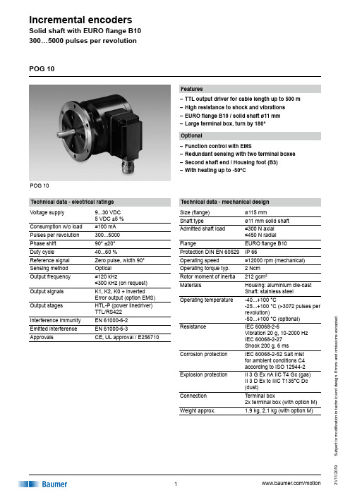
POG 10Features–TTL output driver for cable length up to 500 m –High resistance to shock and vibrations –EURO flange B10 / solid shaft ø11 mm –Large terminal box, turn by 180°Technical data - electrical ratings Voltage supply 9...30 VDC 5 VDC ±5 %Consumption w/o load ≤100 mA Pulses per revolution 300...5000Phase shift 90° ±20°Duty cycle 40...60 %Reference signal Zero pulse, width 90°Sensing method OpticalOutput frequency ≤120 kHz≤300 kHz (on request)Output signals K1, K2, K0 + inverted Error output (option EMS)Output stages HTL-P (power linedriver) TTL/RS422Interference immunity EN 61000-6-2Emitted interference EN 61000-6-3ApprovalsCE, UL approval / E256710POG 10Technical data - mechanical design Size (flange)ø115 mmShaft typeø11 mm solid shaft Admitted shaft load ≤300 N axial ≤450 N radial FlangeEURO flange B10Protection DIN EN 60529IP 66Operating speed ≤12000 rpm (mechanical)Operating torque typ. 2 Ncm Rotor moment of inertia 212 gcm²MaterialsHousing: aluminium die-cast Shaft: stainless steelOperating temperature-40...+100 °C-25...+100 °C (>3072 pulses per revolution)-50...+100 °C (optional)ResistanceIEC 60068-2-6Vibration 20 g, 10-2000 Hz IEC 60068-2-27 Shock 200 g, 6 ms Corrosion protection IEC 60068-2-52 Salt mist for ambient conditions C4 according to ISO 12944-2Explosion protectionII 3 G Ex nA IIC T4 Gc (gas) II 3 D Ex tc IIIC T135°C Dc (dust)Connection Terminal box2x terminal box (with option M)Weight approx.1.9 kg,2.1 kg (with option M)Optional–Function control with EMS–Redundant sensing with two terminal boxes –Second shaft end / Housing foot (B3) –With heating up to -50°CS u b j e c t t o m o d i fi c a t i o n i n t e c h n i c a n d d e s i g n . E r r o r s a n d o m i s s i o n s e x c e p t e d .S u b j e c t t o m o d i fi c a t i o n i n t e c h n i c a n d d e s i g n . E r r o r s a n d o m i s s i o n s e x c e p t e d .POG 10Part number POG10DNMounting type EURO flange B10B3Housing foot B3Voltage supply / signalsI 9...30 VDC / output stage HTL with inverted signals TTL 5 VDC / output stage TTL with inverted signals R 9...30 VDC / output stage TTL with inverted signalsPulse number - see tableOutput signals DN K1, K2, K0Redundant sensingWithout redundant sensingM With redundant sensing (not possible at version with housing foot B3)EMS - Enhanced Monitoring System Without EMS .2With EMSAccessoriesConnectors and cables HEK 8Sensor cable for encoders Mounting accessoriesK 35Spring washer coupling for solid shaft ø6...12 mm K 50Spring washer coupling for solid shaft ø11...16 mm K 60Spring washer coupling for solid shaft ø11...22 mm Diagnostic accessories 11075858Analyzer for encoders HENQ 1100Other pulse numbers on request.Incremental encoder Pulse number 30010002048409650010242500500051212003072Terminal assignmentPOG 10Output signals+UB Voltage supply (for the device); Ground (for the signals); Earth ground (housing)K1; A; A+ Output signal channel 1K1; A; A- Output signal channel 1 invertedK2; B; B+ Output signal channel 2 (offset by 90° tochannel 1)K2; B; B- Output signal channel 2 (offset by 90° tochannel 1) invertedK0; C; R; R+ Zero pulse (reference signal)K0; C; R; R- Zero pulse (reference signal) invertedErr; Err- Error output (option EMS)dnu Do not useTerminal significanceSubjecttomodificationintechnicanddesign.Errorsandomissionsexcepted.S u b j e c t t o m o d i fi c a t i o n i n t e c h n i c a n d d e s i g n . E r r o r s a n d o m i s s i o n s e x c e p t e d .DimensionsPOG 10 - Version with housing foot (B3)POG 10 (POG 10.2, POG 10 M, POG 10.2 M) - Version with Euro flange (B10)POG 10。
纺织品 1-乙烯基咪唑和2-甲基咪唑的测定-最新国标

纺织品1-乙烯基咪唑和2-甲基咪唑的测定警示:使用本文件的人员应有正规实验室工作的实践经验。
本文件并未指出所有可能的安全问题。
使用者有责任采取适当的安全和健康措施,并保证国家有关法规规定的条件1范围本文件描述了采用高效液相色谱仪(HPLC)测定纺织品中附录A所列的1-乙烯基咪唑和2-甲基咪唑的方法。
本文件适用于各类纺织品。
2规范性引用文件下列文件中的内容通过文中的规范性引用而构成本文件必不可少的条款。
其中,注日期的引用文件,仅该日期对应的版本适用于本文件;不注日期的引用文件,其最新版本(包括所有的修改单)适用于本文件。
GB/T6682分析实验室用水规格和试验方法3术语和定义本文件没有需要界定的术语和定义。
4原理试样经乙腈超声萃取,提取液经滤膜过滤后,用高效液相色谱仪(HPLC)测定,外标法定量。
5试剂除非另有说明,所用试剂均为分析纯。
5.1水:GB/T6682中三级水,色谱用水符合GB/T6682中一级水。
5.2乙腈:色谱纯。
5.3氨水。
5.4氨水溶液:0.05%(体积分数)。
移取0.5mL氨水(5.3),用溶解定容至1000mL,摇匀。
5.51-乙烯基咪唑标准物质:CAS号1072-63-5,纯度不小于98.0%。
5.62-甲基咪唑标准物质:CAS号693-98-1,纯度不小于98.0%。
5.7标准储备溶液:质量浓度≥200mg/L,准确称取1-乙烯基咪唑标准物质(5.5)、2-甲基咪唑标准物质(5.6),用乙腈(5.2)配制。
注:此溶液在0℃~4℃冰箱中避光保存,有效期为6个月。
5.8标准工作溶液:准确移取适量的标准储备溶液(5.7),用乙腈(5.2)稀释配制。
注:此溶液在0℃~4℃冰箱中避光保存,有效期为3个月。
6仪器设备6.1高效液相色谱仪(HPLC ):配有二极管阵列检测器(DAD )。
6.2分析天平:分度值分别为0.01g 和0.1mg 。
6.3提取器:具塞密闭,约50mL ,由硬质玻璃制成。
一种SATA Ⅲ的Sigma-Delta小数分频扩频时钟产生器设计

一种SATA Ⅲ的Sigma-Delta小数分频扩频时钟产生器设计龙强;田泽;邵刚;王晋【摘要】整数分频扩频时钟产生器具有较大的频率分辨率,不能满足SATA Ⅲ的要求,针对该问题提出了一种SATA Ⅲ的6 GHz Sigma-Delta小数分频扩频时钟产生器的设计.扩频时钟产生器基于65 nm CMOS工艺,采用了数字MASH Sigma-Delta频率调制技术和一个产生33 kHz的三角波产生器,输出频率达到6 GHz,向下扩频达到5 000 ppm.测试结果表明,在1.2V的电源电压下,功耗为48 mW,非扩频时钟的峰峰抖动为8 ps,电磁干扰降低了15 dB.Sigma-Delta小数分频扩频时钟产生器克服了整数分频器扩频时钟产生器的缺点,较好地满足了SATA Ⅲ的要求.【期刊名称】《无线电工程》【年(卷),期】2017(047)001【总页数】5页(P62-66)【关键词】扩频时钟产生器;Sigma-Delta;SATA Ⅲ;小数分频【作者】龙强;田泽;邵刚;王晋【作者单位】中航工业西安航空计算技术研究所,陕西西安710068;集成电路与微系统设计航空科技重点实验室,陕西西安710068;中航工业西安航空计算技术研究所,陕西西安710068;集成电路与微系统设计航空科技重点实验室,陕西西安710068;中航工业西安航空计算技术研究所,陕西西安710068;集成电路与微系统设计航空科技重点实验室,陕西西安710068;中航工业西安航空计算技术研究所,陕西西安710068;集成电路与微系统设计航空科技重点实验室,陕西西安710068【正文语种】中文【中图分类】TN792近年来,随着芯片的工作速度越来越快,数据率也达到了Gbits/s,由此造成了信号路径中的电压和电流的高次谐波引入的电磁干扰问题愈发严重。
作为高速接口电路中的主要的噪声源,必须采取各种方法降低电磁干扰。
传统的方法主要是通过切断或者减小电磁干扰的辐射量,但是这种方法高昂的成本不适合深亚微米电路。
Eaton Moeller PKZM0电机保护断路器说明书
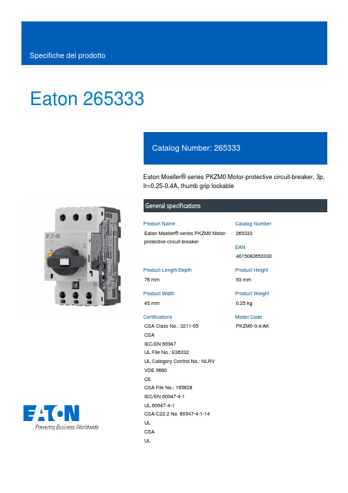
Eaton 265333Eaton Moeller® series PKZM0 Motor-protective circuit-breaker, 3p,Ir=0.25-0.4A, thumb grip lockableGeneral specificationsEaton Moeller® series PKZM0 Motor-protective circuit-breaker265333401508265333076 mm93 mm45 mm0.25 kgCSA Class No.: 3211-05CSAIEC/EN 60947UL File No.: E36332UL Category Control No.: NLRV VDE 0660CECSA File No.: 165628IEC/EN 60947-4-1UL 60947-4-1CSA-C22.2 No. 60947-4-1-14 ULCSAUL PKZM0-0,4/AKProduct Name Catalog NumberEANProduct Length/Depth Product Height Product Width Product Weight Certifications Model Code0.4 A2 x (1 - 6) mm², ferrule to DIN 462281 x (1 - 6) mm², ferrule to DIN 46228Is the panel builder's responsibility. The specifications for the switchgear must be observed.25 °C0.09 kW50 kA, 600 Y/347 V, SCCR (UL/CSA)65 kA, 480 Y/277 V, SCCR (UL/CSA)65 kA, 240 V, SCCR (UL/CSA)Accessories required BK25/3-PKZ0-E150 kAMeets the product standard's requirements.Is the panel builder's responsibility. The specifications for the switchgear must be observed.Does not apply, since the entire switchgear needs to be evaluated.0.4 A, AC-3 up to 690 V0.4 A (3 contacts in series), DC-5 up to 250V10 mm40 °C150 kA eaton-manual-motor-starters-characteristic-characteristic-curve-008.eps eaton-manual-motor-starters-characteristic-characteristic-curve-003.epsDA-DC-00004921.pdfDA-DC-00004892.pdfeaton-manual-motor-starters-pkz-dimensions.epseaton-manual-motor-starters-pkz-dimensions-002.epseaton-manual-motor-starters-pkzm0-3d-drawing.epseaton-manual-motor-starters-pkzm0-3d-drawing-008.epsDA-CE-ETN.PKZM0-0,4_AKIL122023ZUIL03402034ZIL03407010ZDA-CS-pkzm0_ak_neu_aDA-CD-pkzm0_ak_neu_aeaton-manual-motor-starters-transformer-pkzm0-wiring-diagram.epsRated operational current for specified heat dissipation (In) Terminal capacity (flexible with ferrule)10.11 Short-circuit ratingAmbient operating temperature (enclosed) - minRated operational power at AC-3, 380/400 V, 50 HzShort-circuit current rating (type E)Rated short-circuit breaking capacity Ics at 440 V AC10.4 Clearances and creepage distances10.12 Electromagnetic compatibility10.2.5 LiftingSwitching capacityStripping length (main cable)Ambient operating temperature (enclosed) - maxRated short-circuit breaking capacity Icu at 400 V AC 10.2.3.1 Verification of thermal stability of enclosures Characteristic curve Declarations of conformity DisegnieCAD modelGuide utenteIstruzioni di installazione mCAD modelSchemi di cablaggioMeets the product standard's requirements.Ambient storage temperature - min40 °CAdjustment range undelayed short-circuit release - max6.2 A10.8 Connections for external conductorsIs the panel builder's responsibility.ProtectionFinger and back-of-hand proof, Protection against direct contact when actuated from front (EN 50274)Actuator typeTurn buttonRated operational power at AC-3, 440 V, 50 Hz0.12 kWAmbient operating temperature - max55 °CRated operational power at AC-3, 220/230 V, 50 Hz0.06 kWClimatic proofingDamp heat, cyclic, to IEC 60068-2-30Damp heat, constant, to IEC 60068-2-78Device constructionBuilt-in device fixed built-in techniqueFeaturesPhase-failure sensitivity (according to IEC/EN 60947-4-1, VDE 0660 Part 102)Lifespan, electrical100,000 operations (at 400V, AC-3)Static heat dissipation, non-current-dependent Pvs0 WElectrical connection type of main circuitScrew connection10.9.3 Impulse withstand voltageIs the panel builder's responsibility.Number of polesThree-poleRated short-circuit breaking capacity Icu at 690 V AC150 kAAmbient operating temperature - min-25 °C10.6 Incorporation of switching devices and componentsDoes not apply, since the entire switchgear needs to be evaluated.10.5 Protection against electric shockDoes not apply, since the entire switchgear needs to be evaluated.Mounting positionCan be snapped on to IEC/EN 60715 top-hat rail with 7.5 or15 mm height.Rated uninterrupted current (Iu)0.4 ATripping characteristicOverload trigger: tripping class 10 AShort-circuit release± 20% tolerance, Trip blocks6.2 A, Irm, Setting range max.Basic device fixed 15.5 x Iu, Trip Blocks10.13 Mechanical functionThe device meets the requirements, provided the information in the instruction leaflet (IL) is observed.10.2.6 Mechanical impactDoes not apply, since the entire switchgear needs to be evaluated.10.9.4 Testing of enclosures made of insulating materialIs the panel builder's responsibility.10.3 Degree of protection of assembliesDoes not apply, since the entire switchgear needs to be evaluated.Heat dissipation per pole, current-dependent Pvid1.74 WOperating frequency40 Operations/hProduct categoryMotor protective circuit breakerOverload release current setting - min0.25 ARated operational power at AC-3, 690 V, 50 HzRated short-circuit breaking capacity Ics at 400 V AC150 kARated short-circuit breaking capacity Icu at 440 V AC150 kAEquipment heat dissipation, current-dependent Pvid5.22 WHeat dissipation capacity Pdiss0 WRated operational current (Ie)0.4 ASuitable forBranch circuit: Manual type E if used with terminal, or suitable for group installations, (UL/CSA)Also motors with efficiency class IE3Internal resistance10500 mΩTemperature compensation-5 - 40 °C to IEC/EN 60947, VDE 0660-25 - 55 °C, Operating range≤ 0.25 %/K, residual error for T > 40°Terminal capacity (solid)2 x (1 - 6) mm²1 x (1 - 6) mm²Rated frequency - min50 HzShort-circuit current60 kA DC, up to 250 V DC, Main conducting pathsPower loss5.22 W10.2.3.2 Verification of resistance of insulating materials to normal heatMeets the product standard's requirements.10.2.3.3 Resist. of insul. mat. to abnormal heat/fire by internal elect. effectsMeets the product standard's requirements.Lifespan, mechanical100,000 Operations (Main conducting paths)Terminal capacity (solid/stranded AWG)Overload release current setting - max0.4 A10.9.2 Power-frequency electric strengthIs the panel builder's responsibility.Rated short-circuit breaking capacity Ics at 500 V AC150 kAOvervoltage categoryIIIDegree of protectionIP20Terminals: IP00Rated frequency - max60 HzSwitch off techniqueThermomagneticAmbient storage temperature - max80 °CAdjustment range undelayed short-circuit release - min6.2 APollution degree310.7 Internal electrical circuits and connectionsIs the panel builder's responsibility.Rated impulse withstand voltage (Uimp)6000 V ACConnectionScrew terminals10.10 Temperature riseThe panel builder is responsible for the temperature rise calculation. Eaton will provide heat dissipation data for the devices.FunctionsMotor protectionPhase failure sensitiveTightening torque1.7 Nm, Screw terminals, Main cable1 Nm, Screw terminals, Control circuit cablesEaton Corporation plc Eaton House30 Pembroke Road Dublin 4, Ireland © 2023 Eaton. Tutti i diritti riservati. Eaton is a registered trademark.All other trademarks areproperty of their respectiveowners./socialmedia150 kA690 VATEX dust-ex-protection, PTB 10, ATEX 3013, Ex II(2) GD Meets the product standard's requirements.Meets the product standard's requirements.Meets the product standard's requirements.150 kA0.12 kW 25 g, Mechanical, according to IEC/EN 60068-2-27, Half-sinusoidal shock 10 ms690 V Max. 2000 mRated short-circuit breaking capacity Icu at 500 V AC Rated operational voltage (Ue) - min Explosion safety category for dust10.2.2 Corrosion resistance10.2.4 Resistance to ultra-violet (UV) radiation 10.2.7 InscriptionsRated short-circuit breaking capacity Ics at 690 V AC Rated operational power at AC-3, 500 V, 50 Hz Shock resistanceRated operational voltage (Ue) - max Altitude。
- 1、下载文档前请自行甄别文档内容的完整性,平台不提供额外的编辑、内容补充、找答案等附加服务。
- 2、"仅部分预览"的文档,不可在线预览部分如存在完整性等问题,可反馈申请退款(可完整预览的文档不适用该条件!)。
- 3、如文档侵犯您的权益,请联系客服反馈,我们会尽快为您处理(人工客服工作时间:9:00-18:30)。
编号:2010-07-02【11】淮北矿业(集团)有限责任公司
芦岭煤矿排放瓦斯安全措施
矿别:芦岭煤矿
地点: II924-6#眼
时间: 2010年07月12日
淮北矿业集团公司芦岭煤矿排放瓦斯安全措施
2010 年07月12日第2010-07-02【11】号
1.排放瓦斯地点:Ⅱ924-6#眼
2.排放原因:根据矿计划安排,掘进二区将施工II927-2#眼,施工前需要启封密闭
3.巷道及瓦斯情况:巷道长度120米,巷道断面8.0m2,墙内瓦斯浓度3.0%以上,封闭设
置时间为2010年04月10日。
4.制定措施依据:根据国家安全生产监督管理局和国家煤矿安全监察局颁发的《煤矿安全
规程》第140条及集团公司颁发的《关于恢复停工地点生产,排放积聚瓦斯》的制度,特制订本措施。
5.排放时间10年 07月日点分至点分,瓦斯存储量约240立方约需190分
钟。
6.排放瓦斯由矿山救护队、安监处、瓦斯办、掘进二区、保运二区、通风区等共同进行,
排放瓦斯地面总指挥由同志担任,现场总指挥由同志担任;具体分工如下:
(1)掘进二区在启封巷道前将水管接到封闭墙前以备启封密闭墙时湿润墙体;在排瓦斯地点附近的新鲜风流中设置一门电话并保证正常使用;准备好15节风筒和足够长的铁丝;其跟班干部要配合通风区跟班干部共同完成警戒人的安设工作;警戒人负责将警戒区域内的人员和电车全部撤至警戒区域以外,严禁任何人员和电车进入警戒区域以内;
警戒人的撤除工作由掘进二区跟班干部负责进行撤除;所有警戒人由掘进二区负责,并且所有警戒人必须要有明显的警戒标志。
(2)通风区在瓦斯排放前必须确保通风系统合理可靠;在排放瓦斯前通风区必须在瓦斯排放点全风压混合处设置探头,确保断电灵敏可靠;在瓦斯排放过程中,如遇积水或漏顶堵实巷道无法继续进行排放时,通风区应及时打好栅栏揭示警标,待巷道疏通后方可另行编制措施进行排放。
(3)在排放瓦斯前1小时,掘进二区负责将II924-6#联巷内的人员撤至警戒范围之外。
(4)在排放瓦斯前1小时,基建三区必须将II825轨道巷内的所有工作人员和电车撤至警戒范围之外,并切断其所用的动力电源。
(5)在排放瓦斯前1小时,综采二区负责将II824西延轨道巷内看油泵的人员撤至警戒范围之外,并严禁任何人员进入到轨道巷内。
(6)在排放瓦斯前1小时,保运二区必须保证局扇供电正常、主备局扇能够自动倒台,开局扇的人员排放前在局扇前待命。
保运二区负责处切断II水平中部回风上和II84回风上山及II104回风上山内绞车所用动力电;并负责将II823变电所、II824西延变电所和II84变电所内的人员撤至警戒范围之外;排放结束后负责检查开关周围20米范围内的瓦斯情况,符合规定后恢复送电工作。
(7)安监处和瓦斯办负责监督检查措施的落实,并随时检查风流中的瓦斯浓度。
(8)救护队负责扒开封闭和排放瓦斯工作,排放前佩戴呼吸器进入瓦斯区域侦察,摸清瓦斯情况一个小队排放,另一个小队排放时在局扇前待命。
在排瓦斯前救护队必须将“三孔”打开;将墙内积水排净然后自上而下依次扒开。
在瓦斯排放过程中,救护队必须将风筒接至迎头离无法进人地点不大于5米,且风筒吊挂要牢固,压边压实,防止脱节。
(9)调度所负责扒封闭前后的各项事宜。
7.排放瓦斯前通风区要在全风压混合处设置甲烷报警仪,救护队也应在此处悬挂便携式瓦
斯报警仪严格控制风流中的瓦斯浓度。
8.排放前将回风流中的人员和电车全部撤至警戒区以外,切断沿途所有电源,排放时,排
除瓦斯沿途回风流中禁止人员工作。
9.影响范围:II823轨道巷、II824轨道巷、II824西延轨道巷、II82新回风、II104回风
上山、II水平中部回风上、十煤运输大巷、102中部回风上山。
10.安设警戒人具体地点:见图
11.需扒开封闭排放瓦斯的地点,扒封闭时为防止产生火花造成事故,因而必须使用铜顶工
具:钎子、锤。
12.排放瓦斯前,首先检查该地点风流是否稳定,局扇附近的瓦斯情况和是否喝循环风如发
现不安全隐患,待设法排除后,方可进行排放工作。
13.排放瓦斯期间通风区要设专人严格掌握回风流中的瓦斯浓度,排放地点最大不得超过
1.5%其全风压混合后最大不得超过1%,回风流中的瓦斯浓度超过1%时,立即停止排
放,待降到1%以下时再进行排放工作。
瓦斯排放过程中,只有巷道风流中瓦斯浓度不超过1%和二氧化碳不超过1.5%,氧气浓度不低于20%时,稳定30分钟,瓦斯浓度无变化时瓦斯排放工作方可结束。
14.排放瓦斯顺序由外向里,从下向上逐段进行。
15.排出瓦斯的回风所经路线:①Ⅱ924-6#眼→II824西延轨道巷→II104回风上山→十煤运
输大巷→102中部上山→南风井→地面。
②Ⅱ924-6#眼→II824西延轨道巷→II825出架道→II水平中部回风上山→102轨道上山→82石门→南风井。
16.排放瓦斯期间严禁产生明火,参加排放瓦斯人员必须携带矿灯和自救器,并且矿灯必须
符合防爆要求。
17.由排放瓦斯地面总指挥组织参加排放瓦斯有关人员,贯彻排放瓦斯安全措施明确责任。
18.排放瓦斯前排放瓦斯井下现场负责人组织安排回风系统撤人、断电和设置警戒,所有警
戒人和参与排瓦斯的人员必须在措施上签字。
19.排放地点附近的进风流中必须设置电话,保持畅通。
排放瓦斯前后均要用电话通知调度
所及地面总指挥,经地面总指挥同意后方可进行排放。
20.排放人员必须按措施的要求进行组织排放,排放时观察局部通风机是否喝循环风,一旦
出现循环风立即停止排放。
21.排放瓦斯后,由现场负责人组织测气员和电工检查确认排放区瓦斯和二氧化碳浓度,只
有送电开关周围20米范围内瓦斯浓度符合规定。
方可向地面调度所汇报,由地面总指挥下令撤出警戒、恢复送电,宣布排放瓦斯结束。
22.参加排放人员:救护队2个小队,安全监察处 1人,瓦斯办 1人、掘进二区跟班干部1
人,保运二区1人,通风区1人,警戒人21人。
23.排放时将风联开关锁好,严防误送电。
24.排放前,救护队必须先将“三孔”打开,墙内如有积水应先放净,而后在从墙的顶部从
上而下依次扒开。
25.扒开封闭墙的瓦石严禁向墙内推放,以防出现火花。
26.未尽事宜按《煤矿安全规程》执行。
27.警戒人员职责:警戒人1负责严禁任何人员进入II82边界下山以上区域;警戒人2负责
严禁任何人员进入到II82边界下山;警戒人3负责严禁任何人员由II823变电所进入到II823轨道巷;警戒人4负责严禁任何人员由II824轨道车场进入到II824轨道巷;警戒人5负责严禁任何人员进入到II824轨道巷;警戒人6负责严禁任何人员进入到II82回风上山以上区域;警戒人7负责严禁任何人员由II824-9#联巷进入到II824轨道巷;警戒人8负责严禁任何人员进入II82新回风上山;警戒人9负责严禁任何人员进入II824-6#联巷;警戒人10负责严禁任何人员进入到II824轨道巷;警戒人11负责严禁任何人员由II824西延变电所进入到II824西延轨道巷;警戒人12负责严禁任何人员进入到II824西延轨道巷;警戒人13负责严禁任何人员由II842瓦斯道进入到II824西延轨道巷;戒人14、警戒人15、警戒人16负责严禁任何人员进入到II84回风上山;警戒人17负责严禁任何人员进入到II104回风上山;警戒人18负责严禁任何人员由102大联巷进入到II104回风上山;警戒人19负责严禁任何人员进入到8414轨道巷;警戒人20负责严禁任何人员进入到II水平中部回风上山;警戒人21负责严禁任何人员进入到82泵房以里区域。