为什么同样的配件苹果卖588,而小米却只卖149?小米USB
学生使用手机情况调查报告

No one's life is smooth sailing, and no one knows how to grow from birth. It is through constant tempering thatwe learn to grow.整合汇编简单易用(页眉可删)学生使用手机情况调查报告学生使用手机情况调查报告1一、调查目的为了了解当下大学生使用的手机的价位、选取手机的着重点、手机的品牌、等情况进行了本次的问卷调查,以便分析当下大学生在手机消费方面的消费倾向和消费行为,从而了解大学生消费群体的手机市场发展情况。
二、调查背景随着科技的发展和经济的飞越成长,全国的经济面貌焕然一新,人民生活水平迅速提高。
社会信息化进程加快,高新科技产品成为了消费热点,手机作为一种方便快捷通讯工具已经逐步走进了现代生活的各个领域。
对于二十一世纪的大学生来说,在这个信息飞跃的时代,手机几乎人手一部,走在校园中,随处可见大学生一边走路一边拿着款式不同的手机打电话或者发信息,这已然成为了一种生活方式,手机成为了生活中不可或缺的物品。
面对越来越离不开手机的大学生群体而言,大学生手机的使用已经成为一种值得研究的现象。
三、调查内容本次问卷调查的主要内容包括大学生手机使用的品牌、手机使用的时间、用处、价格以及每月的话费等情况。
四、调查概况调查对象:本次的调查对象选取为所有在校大学生调查时间:20__年11月5日——20__年11月10日调查方式:本次问卷采取络问卷的调查方法,将问卷通过QQ等社交平台发放进行随机抽样。
采用络问卷,更能提高效率,减少调查工作量。
电子版调查问卷使用电子邮箱发给大家,无需分配问卷,数据统计便捷。
五、问卷的设计本次问卷调查采用的是络问卷的调查方式,所以选取了腾讯问卷平台制作平台,这样可以方便的将问卷的链接分享到平时使用的腾讯社交软件上面,而问卷的问题主要是围绕大学生使用的手机的品牌、价格等方面设计的。
STIR4200S中文资料

Integrated Mixed-Signal SolutionsCopyright © 2003 SigmaTel, Inc. All rights reserved.All contents of this document are protected by copyright law and may not be reproduced without the express written consent of SigmaTel, Inc.SigmaTel, the SigmaTel logo, and combinations thereof are registered trademarks of SigmaTel, Inc. Other product names used in this pub-lication are for identification purposes only and may be trademarks or registered trademarks of their respective companies. The contents of this document are provided in connection with SigmaTel, Inc. products. SigmaTel, Inc. has made best efforts to ensure that the information contained herein is accurate and reliable. However, SigmaTel, Inc. makes no warranties, express or implied, as to the accuracy or com-pleteness of the contents of this publication and is providing this publication "AS IS". SigmaTel, Inc. reserves the right to make changes to specifications and product descriptions at any time without notice, and to discontinue or make changes to its products at any time without notice. SigmaTel, Inc. does not assume any liability arising out of the application or use of any product or circuit, and specifically disclaims any and all liability, including without limitation special, consequential, or incidential damages.STIr4200USB/IrDA Bridge ControllerVersion 2.0 April ‘03OFFICIAL PRODUCT DOCUMENTATION3-4200-D1-2.0-0403STIr4200USB/IrDA Bridge Controller1.TABLE OF CONTENTS1. TABLE OF CONTENTS (2)1.1. List of Figures (3)1.2. List of Tables (3)2. PRODUCT OVERVIEW (4)2.1. Features (4)2.2. Description (4)2.3. Ordering Information (4)2.4. STIr4200 Block Diagram (5)3. CHARACTERISTICS AND SPECIFICATIONS (5)3.1. Absolute Maximum Ratings (5)3.2. Recommended Operating Conditions (5)3.3. Electrical Characteristics (6)4. FUNCTIONAL DESCRIPTION (6)4.1. Overview (6)4.2. USB Interface (7)4.3. Vendor-Specific Device Requests (7)4.3.1. Write Multiple Registers (7)4.3.2. Write One Register (7)4.3.3. Read Multiple Registers (8)4.3.4. Read ROM (8)4.3.5. Vendor Clear Stall (8)4.4. Digital IR Transceiver (9)4.5. FIFO Contents (9)5. IR FRAMING FORMATS (10)5.1. Transmit Frame Format (10)5.1.1. SIR Transmit Frame (10)5.1.2. FIR Transmit Frame (11)5.1.3. Receive Frame Format (12)5.1.3.1. SIR Receive Frame (12)5.1.3.2. FIR Receive Frame (13)6. DIGITAL IR TRANSCEIVER REGISTERS (14)6.1. Detailed STIr4200 Register Descriptions (14)6.1.1. FIFO Data Register (14)6.1.2. Mode and Baud Rate Registers (15)6.1.2.1. Mode Register (15)6.1.2.2. Baud Rate Register (15)6.1.3. Control Register (16)6.1.4. Sensitivity Register (17)6.1.5. Status Register (17)6.1.6. FIFO Count Registers (LSB,MSB) (18)6.1.6.1. FIFO Count LSB (18)6.1.6.2. FIFO Count MSB (18)6.1.7. DPLL Tune Register (18)6.1.8. IRDIG Setup Register (19)6.1.9. Test Register (19)7. PIN DESCRIPTION (20)7.1. STIr4200S 28-Pin SSOP Pin Description (20)8. PACKAGE DRAWINGS (21)STIr4200USB/IrDA Bridge Controller1.1.List of FiguresFigure 1. STIr4200 Block Diagram (5)Figure 2. Typical USB-IR Application (6)Figure 3. Block Diagram of Digital IR Transceiver (9)Figure 4. SIR Transmit Frame Format (10)Figure 5. FIR Transmit Frame Format (11)Figure 6. SIR Receive Frame Format (12)Figure 7. FIR Receive Frame Format (13)Figure 8. STIr4200S 28-Pin SSOP Pin Assignment Drawing (20)Figure 9. 28-Pin SSOP Package Drawing (21)1.2.List of TablesTable 1. Absolute Maximum Ratings (5)Table 2. Recommended Operating Conditions (5)Table 3. Electrical Characteristics (6)Table 4. Write Multiple Registers (7)Table 5. Write One Register (7)Table 6. Read Multiple Registers (8)Table 7. Read ROM (8)Table 8. Vendor Clear Stall (8)Table 9. IrLAP Frame (9)Table 10. Ir Transceiver Registers (14)Table 11. FIFO Data Register (14)Table 12. Mode Register (15)Table 13. Baud Rate Register (15)Table 14. Mode and Buad Rate Values for Required IrDA Modes of Operation (15)Table 15. Control Register (16)Table 16. Sensitivity Register (17)Table 17. Status Register (17)Table 18. FIFO Count LSB (18)Table 19. FIFO Count MSB (18)Table 20. DPLL Tune Register (18)Table 21. IRDIG Setup Register (19)Table 22. Test Register (19)Table 23. Pin Descriptions for STIr4200S 28-Pin SSOP Package (20)STIr4200USB/IrDA Bridge Controller 2.PRODUCT OVERVIEW2.1.Features•Low-power CMOS design•IrDA data rates from 2.4Kbps to 4Mbps •Obtains power from USB port •Uses standard IrDA transceivers•Optional LED driver for additional flexibility–LED driver capable of > 650ma @ 5V, 25% duty cycle •Full compliance to IrDA 1.3 and USB 1.1 specifications •4Kbyte FIFO buffer memory •Requires a single 12Mhz crystal•Windows 98/98SE/ME/2000/XP™ NDIS/USB driver •Low-profile 28-Pin SSOP package2.2.DescriptionThe SigmaTel STIr4200 is a low cost, low power, USB/IrDA Bridge Controller inte-grated circuit for enabling IrDA wireless data communications through a standard PC USB port. The STIr4200 directly interfaces to both single path and dual path receive IrDA transceiver module architectures and contains a USB controller, IrDA controller, interface logic, and memory buffer for full IrDA 1.3, 4Mbps data transfer rates. A block diagram is hown in Figure 1.The STIr4200 is bundled with a Windows 98/98SE/ME/2000/XP™ NDIS/USB driver for enabling the implementation of a cost effective USB/IrDA Adapter solution for wireless data communications.2.3.Ordering InformationPart Number PackageTemp Range Supply Range STIr4200S28-Pin SSOP0° C to +70° CVdd = 3.1 - 3.6VInfrared Communication TransmissionInfrared TransceiverSigmaTel USB/IrDA Bridge ControllerData TransferUSB Connection to the PCSTIr4200USB/IrDA Bridge Controller2.4.STIr4200 Block DiagramFigure 1. STIr4200 Block Diagram3.CHARACTERISTICS AND SPECIFICATIONS3.1.Absolute Maximum RatingsSymbol Parameter MIN MAX UNITS CONDITIONS P D Power Dissipation (Package constraint) mWT A Operating Temperature070°CT J Lead Solder Temperature260°C for 10 sec max.T S Storage Temperature-55125°CV CC Supply Voltage-0.3 V6VVmax Voltage at any pin V DD + 0.4V VESD Electrostatic Discharge (ESD)+/- 2KV V See Note 1 Note: 1.The device meets the JESD22-A114-A Electrostatic Discharge (ESD) Sensitivity T esting Human Body Model (HBM) requirements of +/- 2KV on all pins, except the TXDIODE pin (Pin 2), where the limit is +/1.5KV.Table 1. Absolute Maximum Ratings3.2.Recommended Operating ConditionsSymbol Parameter MIN TYP MAX UNITS CONDITION V DD Supply Voltage 3.1 3.3 3.6VT A Operating Temperature Range02570°CTable 2. Recommended Operating ConditionsSTIr4200USB/IrDA Bridge Controller3.3.Electrical CharacteristicsT A = 25°C A V DD = 3.3V unless otherwise specified. Cap Load = 50pF Symbol Parameter MIN TYP MAX UNITS CONDITIONI CC Active Supply Current1219mAI CC Suspend Supply Current1450µAV RXDH Receive Data Logic High V DD x 0.8VV RXDL Receive Data Logic Low0.8VV TXDH Transmit Data Logic High V DD x 0.6VV TXDL Transmit Data Logic Low V DD x 0.4VTable 3. Electrical Characteristics4.FUNCTIONAL DESCRIPTION4.1.OverviewThe STIr4200 consists of two major functional blocks, the USB controller and thedigital IR transceiver. The USB controller provides a Control, Bulk-In, and Bulk- Outendpoints to the USB host. The digital IR transceiver consists of a transmit andreceive interface that connects to an analog IR front end. Figure 1shows a block dia-gram of the device.This USB/IrDA Bridge Controller has full interface capability to connect between aUSB bus , and an IrDA-compatible infrared transceiver device. A simplified sche-matic of this arrangement is shown in Figure 2.Figure 2. Typical USB-IR ApplicationSTIr4200USB/IrDA Bridge ControllerB InterfaceThe USB interface to the host controller includes a Control endpoint, a Bulk-In end-point, and a Bulk-Out endpoint. The USB controller supports the USB 1.1 specifica-tion. Hence, it supports all standard functionality associated with deviceenumeration, standard USB device requests, etc. In addition, there is a set of ven-dor specific commands provided to allow a USB driver to access registers in theDigital IR Transceiver and ROM in the USB controller.Note: The STIr4200 device conforms to all of the USB 1.1 specifications with oneexception of the "get_interface" command. This command is used only during USBconformance testing, and during that testing, improper operation will be noted ontest results. However, the software drivers provided by SigmaTel, Inc. do NOT usethat command at all, and this does NOT cause any problem of any kind in operation.A waiver for this command has been obtained from USBIF by SigmaTel, Inc. Thiscommand is not used by the software, and therefore has no effect on device andsystem operation. The only time this "get_interface" command is even accessed isduring USB conformance testing.4.3.Vendor-Specific Device Requests4.3.1.Write Multiple RegistersThe write multiple registers vendor specific command allows the user to write multi-ple sequential registers to the Digital IR Transceiver. Each register is one byte wide,so the command indicates first register to write, the number of registers to write, andthe data phase supplies the data for those registers.Offset Field Size Value (hex)Description0bmRequestType10x40Host to device, vendor type, device recipient1Brequest10x00Write multiple registers2Wvalue2Not used (0x0000)4Windex20x0001–0x000f First register to write6Wlength20x0001–0x000f Number of registers to writeData phase1-15 bytes of Register DataTable 4. Write Multiple Registers4.3.2.Write One RegisterThe write one register vendor specific command allows the user to write a singleregister to the Digital IR Transceiver.Offset Field Size Value (hex)Description0bmRequestType10x40Host to device, vendor type, device recipient1Brequest10x03Write one register2Wvalue2LSB contains data The data to write the register4Windex20x0001 – 0x000f Register to write6Wlength2Not used (0x0000)Table 5. Write One RegisterSTIr4200USB/IrDA Bridge Controller4.3.3.Read Multiple RegistersThe read multiple registers vendor specific command allows the user to read multi-ple sequential registers from the Digital IR Transceiver. Each register is one bytewide, so the command indicates the first register to read, the number of registers toread, and the responding data phase supplies the data from those registers. Thiscommand is also used for the case of reading only one register.Offset Field Size Value (hex)Description0bmRequestType10xc0Device to host, vendor type, device recipient1BRequest10x01Read multiple registers2Wvalue2Not used (0x0000)4Windex20x0001 – 0x000f First register to read6Wlength20x0001 – 0x000f Number of registers to readTable 6. Read Multiple Registers4.3.4.Read ROMThe read ROM vendor specific command allows the user to read the contents of theUSB controller endpoint zero ROM. This is primarily a debug feature that allows ver-ification of the endpoint zero ROM contents. Only 64 bytes of ROM data can berequested at a time. The responding data phase supplies the data from the endpointzero ROM.Offset Field Size Value (hex)Description0BmRequestType10xc0Device to host, vendor type, device recipient1Brequest10x02Read ROM2Wvalue2Not used (0x0000)4Windex20x0000–0x00ff Base ROM address6Wlength20x01–0x0040Number of ROM locations to read (64 bytesmax per request)Table 7. Read ROM4.3.5.Vendor Clear StallThe vendor clear stall command is included as a potential work around for limita-tions in early versions of the Microsoft™ USB driver stack. Although not a concernwith the latest operating systems, the earlier versions could have the possibility thatthe USB driver stack would not properly clear endpoint stalls. The standard deviceclear stall request is also supported.Offset Field Size Value (hex)Description0BmRequestType10x42Device to host, vendor type, endpointrecipient1Brequest10x01Clear endpoint stall2Wvalue2Not used (0x0000)4Windex20x0000 – 0x0002Endpoint on which to clear stall6Wlength2Not used (0x0000)Table 8. Vendor Clear StallSTIr4200USB/IrDA Bridge Controller4.4.Digital IR TransceiverThe Digital IR Transceiver is responsible for driving the transmit diode and receivingthe digital input from an analog IR front end. The primary components are the trans-mit modulator, the receive demodulator, the FIFO, the analog transmit section, andthe register array. Figure 3 shows a block diagram of the Digital IR Transceiver. Byprogramming the registers in the register array, the device’s operation is deter-mined. Various registers are used to specify operations such as the modulationscheme, the baud rate, the current frame size in the FIFO, the RX input selection,etc. The FIFO is 4K bytes in size.Figure 3. Block Diagram of Digital IR TransceiverIn steady state transmit operation, the USB controller is filling the FIFO with datawhile the Digital IR Transceiver is emptying it via the transmit modulator. In steadystate receive operation, the USB controller is emptying the FIFO while the RXdemodulator is filling the FIFO.4.5.FIFO ContentsData sent to the USB controller for transmission by the TX modulator must be orga-nized into frames. An IrLAP frame is made up of the following portions:BOF A C I FCS EOFBOF Beginning of frame(s)A Address fieldC Control fieldI Information fieldFCS Frame check sequence (CRC)EOF End of frameTable 9. IrLAP FrameThe NDIS IR stack only provides the A, C, and I fields to the NDIS mini-port devicedriver that communicates with the USB/IrDA transceiver. Hence, the mini-port mustfill in the BOF, FCS, and EOF fields. Additionally, the driver must add a 2-byteheader ID code and a 2-byte frame size to the packet before passing the packetonto the USB stack for delivery to the USB/IrDA transceiver. There are additionalspecial characters and required escape sequences depending upon the rate oftransfer. Details on the frame format for each of the support rates is discussed in thefollowing sections.STIr4200USB/IrDA Bridge Controller5.IR FRAMING FORMATS5.1.Transmit Frame Format5.1.1.SIR Transmit FrameThe SIR rates include 2.4, 9.6, 19.2, 38.4, 57.6, and 115.2 Kbps. For SIR, the framepresented to the USB bulk transmit interface must be organized in the followingfashion as shown in Figure 4.Figure 4. SIR Transmit Frame Format5.1.2.FIR Transmit FrameThe FIR rate is 4 Mbps The frame organization is detailed in Figure 5.5.1.3.Receive Frame FormatData received into the STIr4200 FIFO from the digital infrared interface can beaccessed by performing a bulk read on the USB interface. The received data con-tains the encoded infrared data. The STIr4200 does not perform any frame valida-tion or CRC-Checking. Multiple frames may exist within one bulk read dependingupon the size of the bulk read. However, the end of the bulk read buffer may notnecessarily coincide with the end of an infrared frame. It is highly likely that the dataat the end of a bulk read will be a partial frame. The remaining frame data will beacquired in the next bulk read.The bulk data thus contains start-of-frame (BOF) characters, end-of-frame (EOF)characters, and escape characters that delineate the actual frame. It is the responsi-bility of the host software to reconstruct the frame.5.1.3.1.SIR Receive FrameThe standard SIR encoding scheme provides all information needed to delineatethe encoded receive frames. Figure 6 summarizes the SIR receive frame formatencoding scheme.Figure 6. SIR Receive Frame Format5.1.3.2.FIR Receive FrameThe FIR encoding scheme is modified slightly from the standard scheme. The char-acter 0x7E is used to delineate the BOF and EOF. The STIr4200 escapes three characters in the data field on receive, 0x7F, 0x7E and 0x7D, which allows the 0x7E characters used as BOF and EOF to be unique. The 0x7E character can then be used to delineate the infrared frame boundaries. This hardware escaping in the data portion is specific to the STIr4200, and the software must un-escape the data portion of the received frame to restore the original data. Figure 7 summarizes the FIR receive frame format encoding scheme.Figure 7. FIR Receive Frame Format6.DIGITAL IR TRANSCEIVER REGISTERS6.1. Detailed STIr4200 Register Descriptions6.1.1.FIFO Data RegisterOffset 0Offset Description AccessBit Position 76543210FIFO Data R/W Reserved 1Mode Register R/W FIRReservedSIRASK FASTRXEN FFRSTEN FFSPRST PDCLK(8)2Baud Rate Register R/W PDCLK(7: 0)3Control Register R/WSDMODE RXSLOW DLOOP1TXPWDRXPWDTXPWR(1: 0)SRESET 4Sensitivity Register RXDSNS(2: 0)BSTUFF R/W SPWIDTH R/W ID(2)ROID(1)ROID(0)RO5Status Register EOFRAME RO FFUNDER ROC FFOVERROCFFDIR ROFFCLR WO FFEMPTY RO FFRXERR ROC FFTXERRROC6FIFO Count (Note 1)Register (LSB)RO FFCNT(7:0)7FIFO Count (Note 1) Register (MSB)RO 0FFCNT(12: 8)8DPLL Tune Register RO DPCNT(5: 0)LONGP(1: 0)9IRDIG Setup RegisterR/W RXHIGHTXLOWReserved Reserved ReservedReserved Reserved Reserved10Reserved R/W Reserved 11Reserved R/W Reserved 12Reserved R/W Reserved 13Reserved R/W Reserved 14Reserved R/W Reserved15Test RegisterR/WPLLDWN LOOPIR LOOPUSB TSTENATSTOSC(3: 0)R/W : Read/WriteRO : Read onlyROC : Read only, clear on read WO : Write onlyNote: 1.Due to double buffering, FFCNT could be off by as much as 3 bytesTable 10. Ir Transceiver Registers7654321FIFO Data ReservedDefault State 00000Bit NumberBit Mnemonic Access Function7 – 0ReservedR/WThe FIFO data register is used internally by the USB interface to access the FIFO data in the digital infrared block. Although this register is accessible through the USB interface, it should never be accessed during normal operation.Table 11. FIFO Data Register6.1.2.Mode and Baud Rate RegistersOffset 1 and 26.1.2.1.Mode RegisterOffset 16.1.2.2.Baud Rate RegisterOffset 2Below is a table of values to be written to the mode and baud rate registers to setthe required IrDA modes of operation:76543210Mode Register FIR ReservedSIR ASK FASTRXEN FFRSTEN FFSPRST PDCLK(8)Default State100Bit Number Bit Mnemonic AccessFunction7FIR R/W When set, puts the infrared modulators into fast infrared mode (4PPM). Must be mutually exclusive with the SIR bit.6Reserved RO Reserved. Write as zero.5SIR R/W When set, puts the infrared modulators into slow infrared mode. Must be mutually exclusive with the FIR bit.4ASK R/W When set, puts the infrared modulators into amplitude shift keying infrared mode.3FASTRXEN R/W Enables simultaneous reads and writes to/from the FIFO.2FFRSTEN R/W Allows the FIFO receive shift register to be automatically reset in FIR mode.1FFSPRST R/W Manually resets the FIFO shift register. Must be set to ‘1’ to release the FIFO shift register from reset.0PDCLK(8)R/WMSB of baud rate register.Table 12. Mode Register76543210Baud Rate Register PDCLK(7: 0)Default State1110111Bit Number Bit Mnemonic AccessFunction7:0PDCLK (7 : 0)R/WSets the divide ratio of the PLL for the infrared modulator/demodulator.Table 13. Baud Rate RegisterOperational ModeSpeed Mode RegisterBaud Rate RegisterFIR4.0 Mbps 0x800x02SIR115.2 Kbps 0x200x0957.6 Kbps0x200x1338.4 Kbps 0x200x1D 19.2 Kbps 0x200x3B 9.6 Kbps 0x200x772.4 Kbps0x210xDFTable 14. Mode and Buad Rate Values for Required IrDA Modes of Operation6.1.3.Control RegisterOffset 376543210 Control Register SDMODE RXSLOW Reserved TXPWD RXPWD TXPWR(1: 0)SRESET Default State00000000Bit Number Bit Mnemonic Access Function7SD/MODE R/W Use this bit only when the STIr4200 is connected to a TEMIC style infraredtransceiver. This bit is used to put the infrared transceiver into the powerdown state or toggle the transceiver between high and low speed.POWER DOWN STATE: Set the SD/MODE bit to enter the power down state.Clear the SD/MODE bit to exit the power down state.SET TEMIC HIGH SPEED: Set the FIR bit (bit 7) in the Mode Register, thenset SD/MODE bit, then clear SD/MODE bit.SET TEMIC LOW SPEED: Clear the FIR bit (bit 7) in the Mode Register, thenset the SD/MODE bit, then clear the SD/MODE bit.The sequences described above for setting the high or low speed modeenables a state machine in the STIr4200 to automatically toggle the TXDATAand UOUT (SD/MODE) pins on the STIr4200.6RXSLOW R/W When set, selects RXSLOW as the receive input. When cleared, selectsRXFAST as the receive input.5Reserved R Reserved4TXPWD R/W When set, powers down the infrared transmitter (modulator).3RXPWD R/W When set, powers down the infrared receiver (demodulator).2-1TXPWR(1: 0)R/W Sets the internal pull down resistance to control the current presented to thetransmit diode.00 : HIGH (max current)01 : MED HIGH10 : MED LOW11 : LOW (min current)0SRESET R/W When set, performs soft reset of the infrared modulator/demodulator.Table 15. Control Register6.1.4.Sensitivity RegisterOffset 476543210 Sensitivity Register RXDSNS(2: 0)Reserved SPWIDTH ID(2: 0)Default State00100ID(2)ID(1)ID(0) Bit Number Bit Mnemonic Access Function7-5RXDSNS(2: 0)R/W Used to program the sensitivity of the DRS demodulator. The correspondingsamples is the number of consecutive samples of an IrDA pulse it takes thedigital detector to declare the presence of a valid IrDA pulse.Value FIR SIR0001400128010312011416100520101Illegal24110Illegal28111Illegal Illegal 4Reserved RO Reserved. Write as zero.3SPWIDTH R/W SIR transmit pulse width. When cleared, the pulse width for SIR modetransmission is 1.6usec. When set, the pulse width is 3/16th the bit rate.2-0ID(2: 0) (Note 1)RO Revision ID of the chip.Table 16. Sensitivity Register6.1.5.Status RegisterOffset 576543210 Status Register Reserved FFDIR FFCLR FFEMPTY Reserved Default State01010Bit Number Bit Mnemonic Access Function7-5Reserved N/A Reserved4FFDIR RO When set, the FIFO is in transmit mode. When cleared, the FIFO is in receive mode.3FFCLR WO When set, clears the FIFO by resetting the pointers to the empty position. This bitmust then be cleared to enable operation of the FIFO. Failing to do so, willprohibit operation of the FIFO. The state of the bit can not be read.2FFEMPTY RO When set, indicates there is no data in the FIFO.1-0Reserved N/A ReservedTable 17. Status Register6.1.6.FIFO Count Registers (LSB,MSB)Offset 6&76.1.6.1.FIFO Count LSBOffset 676543210 FIFO Count Register (LSB)FFCNT(7: 0)Default State00000000Bit Number Bit Mnemonic Access Function7-0FFCNT(7:0)RO When combined with the FIFO Count Registers (MSB), indicates the numberof bytes in the FIFO.Table 18. FIFO Count LSB6.1.6.2.FIFO Count MSBOffset 776543210 FIFO Count Register (MSB)Reserved FFCNT(12: 8)Default State00000000Bit Number Bit Mnemonic Access Function7-5Reserved RO Write as zeros.4-0FFCNT(12:8)RO When combined with the FIFO Count Registers (LSB), indicates the numberof bytes in the FIFO.Table 19. FIFO Count MSB6.1.7.DPLL Tune RegisterOffset 876543210 DPLL Tune Register DPCNT(5: 0)LONGP(1: 0) Default State01010010Bit Number Bit Mnemonic Access Function7-2DPCNT(5: 0)R/W Sets the sensitivity of the receiver’s digital PLL. This bit should be used forchip debug purposes only. This register setting only affects FIR mode. Thedefault setting is proper for normal operation.1-0LONGP(1: 0)R/W Sets the sensitivity of the pulse detector of the receiver. These bits should beused for chip debug purposes only.Table 20. DPLL Tune Register6.1.8.IRDIG Setup RegisterOffset 976543210 IRDIG Setup Register RXHIGH TXLOW ReservedDefault State000Bit Number Bit Mnemonic Read/Write Access Function7RXHIGH R/W When set, this bit inverts the polarity of the data received by thedigital interface on the RXFAST and RXSLOW pins.6TXLOW R/W When set, this bits inverts the polarity of the data transmitted bythe digital interface on the TXDATA pin.5-0Reserved R/W ReservedTable 21. IRDIG Setup Register6.1.9.Test RegisterOffset 1576543210Test Register PLLDWN LOOPIR LOOPUSB Reserved TSTOSC(3 : 0)Default State00000000Bit Number Bit Mnemonic Read/Write Access Function7PLLDWN R/W When set, powers down the secondary infrared transceiver PLL.This bit should be cleared for SIR operation. Two independentPLLs are required in this mode of operation. This bit should beset for FIR operation since the infrared transceiver uses the USBPLL in this mode of operation.6LOOPIR R/W When set, puts the infrared transceiver into internal loop backusing the FIFO to buffer data. This bit should be used for chipdebug purposes only.5LOOPUSB R/W When set, puts the USB interface into loop back mode using theFIFO to buffer data. This bit should be used for chip debugpurposes only.4TSTENA R/W Enables the oscillator to be powered down while in USB SuspendMode.3-0TSTOSC(3: 0)R/W Sets the bias currents for the crystal oscillator circuitry. These bitsshould be used for chip debug purposes only.Table 22. Test Register7.PIN DESCRIPTION7.1.STIr4200S 28-Pin SSOP Pin DescriptionPin NumberSignal Name Type Description 1TX DIODE GND PWR TX DIODE power supply ground 2TX DIODE O Optional LED driver output 3NC No connect 4NC No connect 5RX FAST I Receive data from IR module (Fast)6TX DATA O Transmit data output to IR module 7RX SLOW I Receive data from IR module (Slow)8U OUT O SD/Mode control to IR module 9DGND PWR Digital power supply ground 10V DD PWR Digital power supply (+)11AGND PWR USB transceiver power supply ground 12D NEG I/OUSB interface negative (-) data 13NC No connect 14NC No connect 15NC No connect 16NC No connect 17D POS I/O USB interface positive (+) data 18V DA PWR USB transceiver power supply (+)19U IN I/O Test 20TST-CLK I Test clock input 21TSTD I/O Test data input/output 22TST_EN I Test enable 23RESETZ I Master reset, active low 24GNDD PWR Power supply ground 25XTALI I 12Mhz crystal/clock input 26XTALO O 12Mhz crystal/clock output 27NC No connect 28NC No connectTable 23. Pin Descriptions for STIr4200S 28-Pin SSOP PackageTX DIODE GNDTX DIODEN/C N/C RX FAST TX DATA RX SLOWU OUTD IGITAL GNDV DDA NALOG GNDD NEG N/C N/CN/C N/C X TALO X TALI G ND D R ESET Z T ST_EN T ST D T ST-CLK U IN V DA D POS N/C N/CFigure 8. STIr4200S 28-Pin SSOP Pin Assignment Drawing。
投影仪操作手册说明书

小米手机消费者行为分析

小米手机消费者行为分析摘要近年来,我国移动通讯业发展迅速,手机已渐渐普及。
截至2011年8月底,中国手机用户总数已达9.2726亿户,中国成为全球最大的手机市场。
面对容量巨大且竞争激烈的手机市场环境,小米手机作为国产手机的一个品牌,异军突起。
但小米公司和国内外的手机产业相比也还存在着很大差距。
本文以小米手机营销策略为研究对象,通过对小米手机现行的营销策略、品牌策略、渠道策略、产品策略、价格和促销策略的基本分析,归纳了小米手机现行营销策略存在的主要问题和已具备的优势,最后在前文的基础上,提炼出小米手机营销的启示。
目录一、小米公司简介 (3)(一)小米简介 (3)(二)小米发展经历 (3)二、小米的商业模式分析 (4)(一)小米的战略目标 (5)(二)小米的目标用户 (5)(三)小米的产品和服务 (5)(1)小米手机 (5)(2)MIUI简介 (6)(3)米聊简介 (6)(四)小米的盈利模式 (7)(五)小米的核心能力 (7)(1)产品优势 (7)(2)团队优势 (8)(3)经济优势 (8)(4)销售推广模式 (8)结论 (9)一、小米公司简介(一)小米手机简介小米公司(全称北京小米科技有限责任公司)由前Google、微软、金山等公司的顶尖高手组建,是一家专注于iphone、android等新一代智能手机软件开发与热点移动互联网业务运营的公司。
2011年08月16日,小米手机正式发布,国内媒体第一次接触到这款号称为“中国手机发烧友打造”的智能手机。
小米手机最为瞩目的地方在于硬件配置和价格,作为国产乃至全球目前最强的双核Android手机,小米手机再次刷新了我们心目中的硬件高度。
小米手机采用了高通MSM8260 1.5GHz双核处理器,与HTC G14的CPU相似,但是主频更高。
内存方面是1GB RAM和4GB ROM,完全满足应用的需求。
另外屏幕方面采用的是夏普的4英寸屏幕,材质估计是ASV,分辨率是16:9的854x480,即FWVGA。
USB数据线检验规范
标准修订记录表QJ 珠海格力电器股份有限公司标准QJ/GD 41.09.003代替 QJ/GD 41.09.002QJ/GD 41.09.007QJ/GD 41.09.009 QJ/GD 41.09.010电线电缆检验规范第八部分手机USB数据线2016-12-1发布2016-12-1实施珠海格力电器股份有限公司发布目录目录 (3)前言 (4)USB数据线 (5)1范围 (5)2规范性引用文件 (5)3技术要求 (5)4试验要求和方法 (5)4.1外观 (5)4.2规格尺寸 (6)4.3线芯排列 (7)4.4物理性能 (7)4.5VW-1燃烧试验 (8)4.6摇摆测试 (8)4.7吊重测试 (8)4.8插拨力测试 (8)4.9电气性能 (9)4.10火花试验 (9)4.11耐压测试 (9)4.12盐雾试验 (9)4.13有害物质含量 (9)5检验规则 (10)6标志、包装、运输和存贮 (10)6.1标志 (10)6.2包装 (11)6.3运输 (11)6.4存贮 (11)附录A (规范性附录)检验报告模板 (12)前言珠海格力电器股份有限公司技术标准是公司标准化技术委员会发布的标准,作为公司内部使用的技术法规性文件。
本部分标准与前一版本相比的主要变化如下:——4.1添加了外观判断图本部分标准由珠海格力电器股份有限公司提出。
本部分标准由珠海格力电器股份有限公司标准化技术委员会归口。
本部分标准由珠海格力电器股份有限公司标准管理部起草。
本部分主要起草人:蔡春晓(标管部)本部分标准本次修订人:蔡春晓(标管部)本部分标准于2016年6月首次发布(换版)。
·USB数据线1 范围本部分规定了USB线的技术要求、试验要求和方法、检验规则、标志、包装、运输和贮存。
本部分适用于USB线。
2 规范性引用文件下列文件对于本文件的应用是必不可少的。
凡是注日期的引用文件,仅注日期的版本适用于本标准。
凡是不注日期的引用文件,其最新版本(包括所有的修改单)适用于本文件。
IT8800 使用手册说明书

用户使用手册
直流可编程电子负载
IT8800 系列
型号IT8811/IT8812 IT8812B/IT8812C
© 版权归属于艾德克斯电子有限公司 Ver1.13 /MAR, 2012/ IT8800-701
1
用户使用手册
目录
IT8800 使用手册
第一章 验货与安装 ............................................................... 6
第二章 快速入门............................................................................................................................................ 9
2.1 开机自检 .............................................................................................................................................. 9 2.1.1 介绍 .............................................................................................................................................. 9 2.1.2 自检步骤....................................................................................................................................... 9 2.1.3 如果负载不能启动 ...................................................................................................................... 10
最新大学生使用手机调查报告

大学生使用手机调查报告近年来,随着我国社会的进步,经济的发展,信息化进程的不断加快和提高,高新科技产品成为人们使用和消费的热点。
手机作为其中的代表之一,也不断地被人们关注和亲睐。
而大学生作为一个特殊的群体,他们接受新的事物和想拥有高新产品的欲望比较强烈,尤其是在手机使用方面更为突出,此次的调查研究与分析正是对当前的大学生手机使用情况的进一步了解。
本次调查主要以某一高校的不同学院的同学作为调查对象,通过问卷的形式较全面的了解当代大学生手机的使用情况。
一、大学生开始使用手机的时间经过问卷调查基本了解,手机在大学生中使用广泛,几乎每一位大学生都有一部手机。
大多的大学生开始使用手机的时间是高中,占被调查人数的60%,有34%的大学生是在大学才开始使用手机的,更有5%的同学在初中就开始使用手机20xx年大学生使用手机调查报告20xx年大学生使用手机调查报告。
二、大学生对手机附加功能的要求在当今互联网发展迅速的情况下,更多的大学生对手机能否上网有一定要求,调查显示70%的大学生希望手机带有上网的功能。
另外对带有游戏的要求占35%,照相也是一种需求大的功能,大约有60%的大学生要求手机能带照相,还有40%的大学生乐于手机能带MP4。
三、平时使用手机做哪些事当代的手机功能齐全,大学生们使用手机主演用于通讯、上网浏览网页、听歌看电影、照相和看小说,它们分别占了调查人数的70%、76%、31%、29%和28%。
四、一个月的消费情况大学生手机消费占了生活费的一部分,但总的来说,大学生手机的消费都不是很高。
经调查:一个月消费20元以下的占了8%,更多的人消费20—50元,它们占了60%;其他的在50—100元之间的有23%;100元以上的有8%。
五、大学生对手机价格的敏感程度63%的大学生能接受的价格区间在500——1000元之间,10%的大学生能接受的价格在500元以下,27%愿意考虑1000——20xx元的手机,没有能够接受更高的价格的同学。
电子邮件系统方案

J I N D I®M A I L S Y S T E M S O L U T I O N 金笛®电子邮件系统方案电话:***********/76/77传真:***********-6004北京春笛网络信息技术服务有限公司中国·北京市海淀区知春路23号863软件园量子银座903______________________________________________ jindi®mail, 金笛®, jdmail 均指金笛®邮件系统目录简介 ............................................................................................................................................. - 5 - 概论 ............................................................................................................................................. - 6 - 需求篇 ......................................................................................................................................... - 7 - 基本功能需求...................................................................................................................... - 7 - 系统扩展需求.................................................................................................................... - 10 - 其它需要考虑的................................................................................................................ - 10 - 产品篇 ....................................................................................................................................... - 11 - 产品介绍............................................................................................................................ - 11 - 体系结构............................................................................................................................ - 11 - 技术架构............................................................................................................................ - 12 - 金笛®邮件系统五大功能模块逻辑关系图............................................................. - 12 -金笛邮件系统技术架构优势:................................................................................ - 13 -金笛®邮件的主要技术特点..................................................................................... - 14 - Jindi®mail 主要功能..................................................................................................... - 24 - -用户管理................................................................................................................ - 24 --域管理.................................................................................................................... - 24 --公共地址簿............................................................................................................ - 24 --用户组管理............................................................................................................ - 25 --系统设置................................................................................................................ - 25 --全局过滤规则设置................................................................................................ - 28 --邮件监控................................................................................................................ - 28 --反垃圾、反病毒设置............................................................................................ - 28 --日志查看................................................................................................................ - 30 --系统备份................................................................................................................ - 30 --注册码管理............................................................................................................ - 30 --邮件管理................................................................................................................ - 31 --邮件全文检索:.................................................................................................... - 31 --设置........................................................................................................................ - 31 - Jindi®mail功能偏移表..................................................................................................... - 32 - Jindi®mail邮件系统测试性能指标................................................................................. - 34 - WebMail页面服务器的性能............................................................................................ - 34 - 单机测试邮件服务器性能测试(10K邮件,本地投递) ............................................ - 34 - 邮件服务器性能测试(300K邮件,本地投递) .......................................................... - 35 - NAS存储结构模拟环境测试结果................................................................................... - 36 - 设计篇 ....................................................................................................................................... - 38 - 设计目标............................................................................................................................ - 38 - 底层坚固、高度稳定。
物料描述规则.doc
文件编号:WJ2011110401B
RIGOL
物料描述规则(修订版) 制定日期:2020-1-3 12 时 15 分 2011-11-04
版本:02
页码:1 ,为了保证物料主数据进入系统管理达到数据准
确性、唯一性,有效性,同时规范标准化管理,并且保证公司的ERP系统正常运行,特指定本物料描 述规则。
RIGOL
物料描述规则(修订版)
文件编号:WJ2011110401B 制定日期:2020-1-3 12 时 15 分 2011-11-04
版本:02
页码:2 -40
四、物料描述规则一览表
目录
1. 电阻/普通电阻 ......................................................................................................................................................... 6 2. 电阻/电阻网络 ......................................................................................................................
国际市场营销范文_共10篇
★国际市场营销论文范文_共10篇范文一:国际市场营销英文论文[键入文字]**信息工程大学学生姓名:专业班级:论文日期:国际市场营销导向对企业产生的影响TheinfluenceofinternationalmarketingorientationontheenterpriseAbstractInternationalMarketingUndertheinfluenceofeconomicglobalization,InternationalMarketingreferstotheinflowofgoods andservicesofmorethanonecountryinthehandsoftheconsumeroruserprocess.Inotherwords,internationalmarketing**soci alandacross-bordermanagementprocess,enterprisesthroughplanning,pricing,proionandguidance,tocreateandexchangeofproductsandvalueintheinternationalmarkettomeettheneedsofmultinationalcustomersandaccessprofitactivities。
Worldeconomy,technologicaldevelopmentisuneven,especiallytoday’shighlydevelopedscienceandtechnology,nocoun trycan’thavealltheresourcesneededforthenationalecon omy,nottohavealltheadvancedtechnologydevelopmentneeds.Toacceleratethedevelopmentofthenationaleconomy,weneedtoactivelycarryoutinternationalmarketing,domesticproductsintotheinternationalmarket。
诺基亚 6220c 说明书
PLUSTEK USB扫描仪 软硬件安装

最详细的快充技术科普
从入门到精通最详细的快充技术科普2015年下半年的机型,基本上都配备了快速充电技术。
一般来说,我认为充电功率超过10W(也就是5V 2A)才能称之为快速充电。
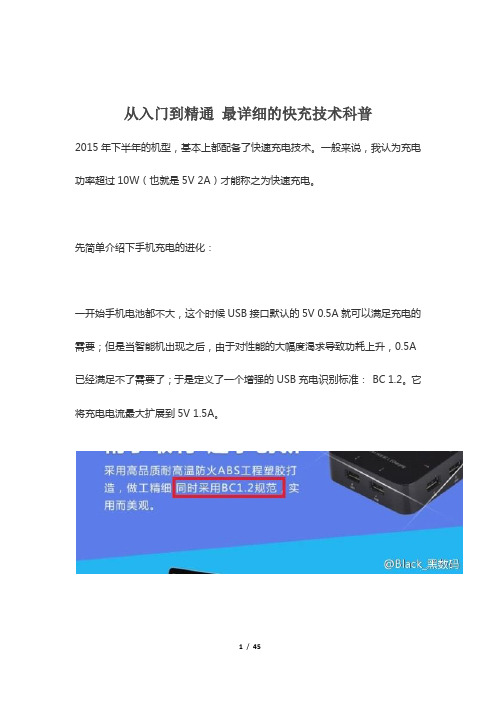
先简单介绍下手机充电的进化:一开始手机电池都不大,这个时候USB接口默认的5V 0.5A就可以满足充电的需要;但是当智能机出现之后,由于对性能的大幅度渴求导致功耗上升,0.5A 已经满足不了需要了;于是定义了一个增强的USB充电识别标准:BC 1.2。
它将充电电流最大扩展到5V 1.5A。
但是到了2013年左右,出现了3000毫安时以上的智能手机,这个时候就算是5V 1.5A也不能满足需求了,于是再次扩展到5V 2A。
常识1:手机充电电流是手机来控制的,而不是充电器。
也就是说手机就是大坝,充电器只是水库,手机会智能检测充电器的负载能力,充电器功率大质量好,手机就会允许充电器加载更高的电流;充电器设计输出电流过小,那么手机也会限制给自己充电的电流。
这就是为什么我们要选购大功率充电器的原因,例如一台手机最大支持5V 1.5A 的输入,你买个5V 1A的充电器,就会导致手机只能以5V 1A来充电,不仅充电速度慢,而且因为充电器一直全负荷工作发热严重;反之你买个5V2A的充电头,手机会控制只输入1.5A的电流,充电器负载较低,有充足的余量。
没错我其实说的就是苹果,iPhone 6/Plus分别最高支持5V 1.5A/2A的充电,但是吝啬的苹果标配充电器只有5V 1A。
对于1800多毫安电池的iPhone6来说其实无关紧要,但是对于接近3000毫安时电池的iPhone6 Plus来说简直要了亲命!实际测试中,iPhone 6 Plus使用iPad充电器的峰值充电电流能到5V 1.9A,原因只有一个那就是节省成本,毕竟库克是要赚大钱的人。
任何脑残果粉妄图在这个问题上洗地都是可笑的行为。
目前来看,iPhone 6S/6S Plus应该也会延续这个风格,大家可以在富连网上抢先购买,然后再买一个iPad充电头,齐活~~好的,我们继续谈历史。
AG58B微型热敏打印机使用说明书

4 / 12
AG58B 使用说明书
3.1.2 串行接口
AG58B 串行接口支持 RS232 电平、TTL 电平和 RS485 电平,由具体型号而定。接口类型 为 IDC10 针型插座。
出厂默认波特率为 9600,起始位 1 位,数据位 8 位,无校验位,停止位 1 位。波特率 可以通过按键设置更改,具体参考 3.3.3 节“参数设置”。串口连接方式如下图所示:
注:普通机型出厂默认支持连接方式 1(232 电平)和连接方式 3(TTL 电平)。
图:串口连接方式
注:使用连接方式 1 或 2 时,TTL 座加三个短路跳线帽;使用连接方式 3 时,RS232 座
嵌入深度:47 mm
3.1 接口说明
3.1.1 电源接口
AG58B 打印机支持两种供电方式:1、4.5~8.5v 15W 直流电源;2、9~24v 30W 直流电源。 供电方式由具体的型号而定。电源接口示意图如下图所示:
引脚号 1 2 3
信号 Vdc N.C. GND
图:电源接口示意图 说明 打印机工作电源。 空 地
AG58B 微型热敏打印机
使用说明书
V1.01
蚂蚁(东莞)科技发展有限公司
AG58B 使用说明书
目录
目 录 ....................................................................................................................................................... i 一.特征与性能指标........................................................................................................................ 2 1.1 主要特征................................................................................................................................... 2 1.2 性能指标.................................................................................................................................. 2 1.3 型号说明.................................................................................................................................. 3 二.安装说明................................................................................................................................. 3 2.1 打印机外形.............................................................................................................................. 3 2.2 外观尺寸.................................................................................................................................. 4 三.操作说明................................................................................................................................. 4 3.1 接口说明.................................................................................................................................. 4 3.1.1 电源接口....................................................................................................................... 4 3.1.2 串行接口....................................................................................................................... 5 3.1.3 并行接口....................................................................................................................... 6 3.1.4 USB 接口 ........................................................................................................................ 7 3.1.5 电源通讯接口............................................................................................................... 7 3.2 指示灯说明.............................................................................................................................. 8 3.3 按键操作说明........................................................................................................................... 8 3.3.1 走纸............................................................................................................................... 8 3.3.2 打印自检....................................................................................................................... 8 3.3.3 参数设置....................................................................................................................... 8 四.打印命令............................................................................................................................... 10 五.使用与维护........................................................................................................................... 10 5.1 清洁维护................................................................................................................................ 10 5.2 产品维护................................................................................................................................ 10 5.2.1 打印机使用注意事项................................................................................................. 10 5.2.2 打印机故障分析及排除............................................................................................. 11
映美打印机说明书
Thecus N4100PRO 使用说明

使用说明版权和商标公告ndows, Thecus和Thecus产品的其他名字的注册商标为Thecus科技有限公司。
Microsoft, Wi和Windows标志的注册商标为微软公司。
Apple, iTunes和Apple OS X的注册商标为苹果电脑公司。
所有其他商标和品牌名称都是他们各自的所有人的财产。
如未经通知,说明书以改版为准。
版权(C) 2008 Thecus 科技公司。
版权所有关于这份手册这份手册里的所有信息已经很被仔细地核实,以确保它的正确性。
如果发生错误,请给我们反馈。
在未通知的情况下,Thecus科技公司对这份手册内容的修改保留权利。
产品名称: Thecus N4100PRO手册版本: 1.2出厂日期2008年10月有限担保Thecus科技公司担保Thecus N4100PRO的所有部件在他们离开工厂之前都经过全面地测试,还有必须在一般使用的情况下能正常地运作。
一旦发生任何系统故障,如果产品在保修期内,在正常使用的情况下出现故障,Thecus科技公司,当地代表和经销商有责任对客户进行免费保修。
Thecus科技公司不对任何由产品引起的任何数据损坏或损失负责任。
强烈推荐用户进行必要的备份操作。
安全警告对于您的安全方面,请阅读并按照下面的安全警告。
请在安装您的N4100PRO.之前全面地阅读这份手册。
你的N4100PRO是一复杂的电子设备。
不要在任何情况下尝试修理它。
在发生故障的情况下,立即关掉电源,然后到合格的服务中心修理。
对于细节方面联系你的经销商。
不要在电源线上放置任何东西。
不要把电线放在任何可以被踏着走的地方。
谨慎地放好连接电缆,避免他们受到踩踏。
在温度为0°C 和40°C 之间,伴随着20% – 85%的相对湿度,你的N4100PRO可以正常运作。
在极端的环境条件下使用N4100PRO可能会损坏它。
确保给N4100PRO正确地供电(AC 100V ~ 240V, 50/60 Hz,3A). 把N4100PRO插到不正确的电源会被损坏。
学生使用手机情况调查报告

学生使用手机情况调查报告学生使用手机情况调查报告1一、调查目的:近些年来,通信业成为我国发展最快的行业之一,其发展对我国社会经济的推动有着十分深远的意义。
由于经济迅速发展,人们生活水平不断提高,21世纪手机技术不断成熟,各种手机品牌也如雨后春笋般涌现出来。
随着4G网络的不断发展,人们对于手机的要求也越来越多。
作为一名通信工程专业的学生,我觉得有必要了解现在大学生对于各种智能手机的使用情况,掌握大学生对于未来通信的期待。
二、调查过程:调查人员:调查时间:调查地点:教室、餐厅、公寓楼调查对象:在校大学生调查方法:调查人员于xx年3月10日中午在教室、餐厅、公寓楼随机选取有空闲时间的同学,帮助填写大学生智能手机使用情况的调查问卷(调查问卷详见附录)。
三、调查结果:在此次调查中,我们主要就大学生使用手机的品牌、价格、质量、系统、时长、运营商等几方面进行调查研究,抽样调查将近300人,收回有效问卷大概273份。
在我们此次的调查结果中,在大学生手机品牌的使用方面,小米以23.1%居于第一位,苹果以18.95%屈居第二,三星则以17.3%位列第三。
第四位是占有率7%的华为。
而联想、HTC、vivo等品牌的占有率各在5%上下。
其余品牌如中兴、魅族、索尼、酷派、金立、OPPO等占据剩余20%左右。
在手机价格方面,大学生手机的平均价格在2700元左右。
其中20xx元以下的为25.4%,20xx元到3000元的为36.1%,3000元到5000元的为30%,而5000元以上的有6%左右的人。
由此可见,现在的大学生买手机也没有盲目的追求高价格。
并且,相较于价格而言,多数大学生还是比较看中手机的功能以及外形。
调查显示,有36%的同学表示在购买手机时,会优先考虑手机的功能,有32%的同学表示比较注重手机的外形,还有另外的27%的同学则会较为看重价格。
而在手机的性能方面,超快的运行速度是大学生比较向往的,有32%的同学选择了此项,而高像素、大屏幕也同样成为大学生注重的两个方面,入选率均超过了20%。
FT6800大功率电子负载用户手册 使用说明书
产品定价建议

产品定价建议嘿,咱今儿就来聊聊产品定价这档子事儿!你说这定价吧,就好比给咱的宝贝找个合适的位置。
定高了,人家嫌贵不买账;定低了,咱自己又觉得亏得慌。
你想想看,这就跟咱去菜市场买菜一样。
那卖菜的要是把价格定得死贵死贵的,咱是不是得扭头就走,心里还得嘟囔几句?可要是价格特别便宜,咱是不是也得犯嘀咕,这菜会不会有啥问题呀?所以说啊,这定价可得好好琢磨琢磨。
咱先说说成本这一块儿。
你得把所有的成本都算进去啊,原材料、人工、运输啥的,一个都不能少。
可别小看这些成本,加起来可能吓你一跳呢!要是不把这些考虑清楚,到时候卖出去发现亏了本,那可就得哭鼻子咯!这就好像你打算出远门,不把路上要花的钱准备够,那不就得饿肚子嘛!然后呢,还得看看市场行情。
人家都卖多少钱啊?咱的产品有啥特别的地方能让咱定价高一点或者低一点?这就好比大家都在卖苹果,你的苹果又大又甜,那是不是就能多要点钱?要是你的苹果普普通通,那你就得跟着大部队走,价格别太出格咯。
还有啊,咱得考虑考虑目标客户。
他们愿意花多少钱买咱的东西?他们的消费水平咋样?要是咱的东西是卖给那些有钱人的,那价格可以稍微定高一点,他们可能不在乎那点钱。
可要是咱的目标客户是普通老百姓,那价格就得亲民一点,不然他们可不会买账哟!这就跟你去买衣服一样,你要是去高档商场,那价格肯定高;要是去地摊儿,那价格肯定就便宜。
再说说品牌形象。
要是你的品牌特别响亮,大家都认可,那你定价的时候就可以有点底气。
就像那些名牌包包,价格高得离谱,可还是有人抢着买,为啥?不就是因为牌子响嘛!但要是你的品牌没啥知名度,那你就得悠着点了,别一下子把价格定得太高,不然谁认识你呀!咱举个例子哈,你看那手机市场。
苹果手机,人家品牌牛啊,所以价格就高。
可有些国产手机,品牌没那么响亮,就得靠性价比来吸引顾客。
原创不易,请尊重原创,谢谢!。
关系营销案例分析——小米

客户关系管理
用户参与设计 向心力
粉丝协助
口碑
用户参与设计
在小米官网的论坛
里,米粉有任何的建议、
指责都可以在此发表。
MIUI的使用接口如:通
讯簿的拼音搜寻、特殊
声控指令立即拍照等功
能都是由用户提议。
向心力
在中国,小米 有112个同城会(地 方粉丝社团),人 数近千万,一年下 来大大小小的米粉 聚会约有60场。
据不完全统计,目前与小米达成合作的A股上市公司 达到9家之多,其中深圳公司占了绝大多数。华南地区 可以说是小米手机的生产中心。小米往往一样的产品 会分给许多不同的工厂完成,以此相互牵制。据了解, 小米旗下代工厂达到上百家之多,而据这些上市公司 公布年报看来,小米并未成为任何一家公司的前五客 户。一位小米电池代工厂内部人士透露:“小米只能 算是我们的前8客户。” 与此同时,小米手机产量不断增加,智能硬件的开 发也加大了小米的产出,在பைடு நூலகம்个过程中,为了保证小 米手机高性价比的特点,小米对于价格的掌控也引发 了一些供应商的不满。
获取供应商的支持
结果 小米的努力在2011年年初至年中收获成效。在日 本的那次会晤之后,夏普同意供应LCD触屏。高通也 决定供应处理器,因为它认为小米的开放创新式MIUI 操作系统前途无量。在关键部件的供应敲定后,代工 iPhone的台湾富士康(Foxconn)同意装配新款小米手机。 /watch/63082287305028407 23.html?page=videoMultiNeed
供应链管理
从小米供应链的布局上来看,分散供应商, 向内地转移的趋势已经显现。据记者不完全统 计,与小米结盟的国内供应商有上百家之多, 其中上市的公司达到了12家,为小米提供不同 的芯片、结构件等手机零配件。 目前小米的整体供应链中心以台湾和中国大 陆为主,其中小米台湾系供应商主要有负责组 装的代工厂富士康和英业达,手机芯片制造商 联发科,提供面板的友达,开发驱动IC方案的 联咏、相机镜头厂大立光等。
- 1、下载文档前请自行甄别文档内容的完整性,平台不提供额外的编辑、内容补充、找答案等附加服务。
- 2、"仅部分预览"的文档,不可在线预览部分如存在完整性等问题,可反馈申请退款(可完整预览的文档不适用该条件!)。
- 3、如文档侵犯您的权益,请联系客服反馈,我们会尽快为您处理(人工客服工作时间:9:00-18:30)。
为什么同样的配件苹果卖588,而小米却只卖149?
小米USB
7月28日小米发布了旗下两款笔记本,标志着小米正式进军PC行业,生态链配件docking也随之诞生。
今天要拆解的这款型号为ZJQ01TM的USB-C至HDMI多功能转接器,由北京米田科技有限公司制造,属于小米生态链企业。
该转接器为一转三设计,可扩展出USB Type-C、USB Type-A、HDMI 各一个,这样在充电的时候,依然可以获得USB Type-C。
最高支持5Gbps数据传输、4K视频输出、3D格式传输,还支持USB-C PD 2.0电力传输规格,可实现5V-20V/0-3.25A多级电压电流自动匹配,最大供电能力为65W,而小米两款笔记本标配充电器的功率分别为65W、45W,足以满足所需。
产品外包装采用白色包装盒,正面印有docking图案。
背面上部是开口封条,一个挂孔。
背面下部,印有型号,制造商等,北京米田科技有限公司制造,属于小米生态链企业。
