5. Coating techlonogy
YFluo涂层技术
YFluo TM 涂层技术YFluo TM Coating Technology1.YFluo TM 涂层技术概述YFluo TM Coating Technology Introduction在工业生产过程中,各种各样腐蚀因素对生产造成了很大的影响,腐蚀不仅降低了设备和管线的使用寿命,而且增加了维修频率、维护成本,严重的腐蚀甚至会影响设备、生产及人员的安全。
During the industrial manufacturing process, there are many corrosive factors exerting great influence on production. Corrosion shortened the using lifespan of equipment & pipelines and increased maintenance cost frequency. Worse more, serious corrosion directly affected the safety of equipment, production and workers.YFluo TM防腐涂层有特殊的前处理涂层和特殊的氟聚合物顶层涂层两层结构构成。
前处理工艺保证了产品的物理性能没有变化,氟聚合物顶涂更好的抵抗各种化学品和海水的腐蚀;与一般性的PTFE涂层不同之处,其防腐性能更强,针对不同的腐蚀环境,可为客户提供量身定做的产品,以满足不同工况条件下的性能需求。
YFluo TM has a two-layer structure of special pre-treatment polymer film and under-treatment layer. Pre-treatment technic insures the physical performance of product without changing and fluropolymer top coating results in a better performance in resisting chemical and seawater corrosion. YFluo TM coating is different from PTFE because of their strong corrosion resistant ability. Further, YFluo TM can be verified as per different customers’request so that can up to various environment working condition requests.YFluo TM防腐涂层工艺融合了先进的前处理技术,其涂层超薄却有极强的耐腐蚀性能,延长了产品的使用寿命;具有不粘、低摩擦力性能,可以提供稳定的扭矩系数,便于安装和拆卸;抗多种化学品腐蚀;耐候性强,适应各种极端的环境;多颜色区别,便于安全等级划分管理。
武汉理工大学:涂料与涂装工艺学 电子教案

武汉理工大学教案课程名称:涂料与涂装工艺学Paint and Coating Technology专业:化学工程与工艺年级:2006级学年:第3学年学期:第6学期任课教师:张学敏魏铭编写时间:2009《涂料与涂装工艺学》教案课程名称:涂料与涂装工艺学/Paint and coating Technology课程类别:涂料涂装方向限修课适用专业:化学工程与工艺总学时:48学时先修课程:有机化学、高分子化学本课程目的:通过向学生传授现代涂料研究和生产的基本理论、生产工艺、现代涂漆工艺和方法等知识,拓展学生的知识面,巩固和加强学生的基础理论和专业知识,并使学生在知识的综合运用方面得到训练,提升学生的创新能力。
本课程各章教学内容:§1绪论,2h§2合成树脂,8h §3颜料,4h§4溶剂,4h§5助剂,2h §6涂料配方设计,4h§7涂料生产工艺,2h§8涂料种类与特性,2h§9涂料的选用,2h§10漆前处理,4h§11涂装方法和装备,4h§12涂料干燥与成膜,2h§13涂漆工艺,6h期中考查,2h课程改革与特色本课程用powerpoint课件教学,并采用丰富的图片资料提高学生的认识、理解能力;由于涂料是涂装的基础,故在课程中间进行期中考查,便于在教与学的过程中及时发现问题并立即得到解决,使学生更好地掌握涂料与涂装的系统知识。
由于本课程知识是众多基础知识的综合体现与应用,与社会生产实际联系紧密,本专业知识的发展依赖于相关基础学科的最新成就和发展,采用创造性学习法教学,锻炼学生获取与应用新知识、锻炼学生综合应用知识、培养学生在实际工作中的创新能力。
教材:张学敏等.涂料与涂装技术.化学工业出版社,2006.1参考书与文献资料:1.F. P. Henry “Organic Coating Technology”(V olume 2), John Wiley &Sons, Inc. 19692.[J] Journal of Coatings Technology3.[J] Progress in Organic Coatings4.[J] Modern Paint and Coatings5.[J] World Surface Coating Abstracts6.[J] Paint Manufacture7.[J] Paint and Resin8.[J] Polymers Paint Color J9.Z.W.威克斯,F.N.琼斯,S.P.柏巴斯.有机涂料科学技术.化学工业出版社,2002.310.张学敏.涂装工艺学.化学工业出版社,2002.911.叶扬祥等.涂装技术实用手册.机械工业出版社,2003.6第1章:1.教学目标及基本要求:对本课程知识体系及框架结构有个整体了解,使学生制订和安排本课程学习计划正确理解下例概念、定义或相互关系:主要成膜物质(基料)、次要成膜物质。
包胶 专业术语英文
包胶专业术语英文全文共四篇示例,供读者参考第一篇示例:包胶是指在物品表面进行一层封装,以保护物品表面,并提升物品的质感和外观。
在包胶过程中,会使用一系列专业术语,下面我们来了解一些关于包胶的专业术语英文。
1. Resin:树脂,指用于包胶的主要材料,通常为环氧树脂或聚氯乙烯。
2. Coating:涂层,指包胶过程中形成在物品表面的薄膜。
3. Curing agent:固化剂,指用于加速树脂固化的化学物质。
4. Hardener:硬化剂,与树脂搭配使用,用于改变树脂的硬度和强度。
5. Glossy finish:光泽表面,指包胶后物品表面呈现出的光滑、有光泽的效果。
7. Adhesion:粘附性,指包胶后涂层与物品表面的附着力。
9. UV resistance:抗紫外线性能,指包胶涂层具有抵抗紫外线照射的能力。
11. Epoxy resin:环氧树脂,一种常用的包胶材料,具有优异的耐化学腐蚀和耐磨损性能。
13. Silicone coating:硅橡胶涂层,具有良好的耐高温性能和抗老化性能。
14. Water-based coating:水性涂层,一种环保的包胶涂层材料,具有低VOC排放。
第二篇示例:包胶专业术语英文包胶是一种在包裹材料中添加一层胶涂层的加工方式,以增加包装材料的防潮、防水、防氧化等功能。
在包胶行业中,有许多专业术语和名词,以下将对一些常用的包胶专业术语进行英文介绍。
1. 包胶(Coating)包胶是指用聚乙烯、聚氯乙烯、聚丙烯等塑料或树脂制成的涂层覆盖在被包装物表面的一种包装方法。
包胶可以有效提高被包装物的防潮、防水、保鲜等性能。
3. 弹性包胶(Elastic Coating)弹性包胶是指具有一定韧性和弹性的包胶材料,能够更好地适应被包装物的形状和大小。
4. 热封包胶(Heat Seal Coating)热封包胶是指可以通过加热和压力将胶涂层与包装材料或被包装物粘合在一起的包胶材料。
云南省昆明市西山区2023-2024学年八年级下学期期末考试英语试题
云南省昆明市西山区2023-2024学年八年级下学期期末考试英语试题一、单项选择1.Menglan is ________ adult panda in Beijing Zoo.A./B.an C.the D.a 2.Sometimes, we can stop our steps to enjoy the ________ of nature.A.excitement B.difficulty C.beauty D.relation3.________ is impossible if you work hard.A.Nothing B.Everything C.Something D.Anything 4.Everyone is special, so don’t compare yourself ________ others.A.with B.by C.on D.in5.Please keep the door ________. We need more fresh air.A.closed B.open C.dirty D.clean6.Mike is very interested in Chinese culture, and he ________ Chinese for three years.A.learns B.is learning C.will learn D.has learned 7.Life is like riding a bicycle. To keep your balance (平衡), you ________ keep moving.A.could B.could not C.should D.shouldn’t 8.Please don’t feed animals at the zoo, ________ the animal keeper allows you to do so.A.if B.unless C.and D.but9.V olunteers are raising money to ________ a hospital for the old and the sick.A.set up B.wake up C.give up D.cheer up 10.Mary’s parents usually encourage her ________ her feelings bravely.A.express B.expressing C.to express D.expressed二、完形填空从题中所给的A、B、C、D四个选项中选出能填入空白处的最佳选项,并将所选答案涂到答题卡的相应位置上。
Surface & Coatings Technology
Surface & Coatings Technology Influences of binder on fire protection and anticorrosion properties of intumescent fire resistivecoating for steel structureArticleinfo:Article history:Received 31 May 2009Accepted in revised form 23 October 2009Available online 30 October 2009Keywords:IntumescentFire resistive coatingBinderFire protectionAnticorrosion propertyAbstract:The combination of epoxy emulsion and self-crosslinked silicone acrylate (SSA) emulsion was used as mixed binder for preparing water-borne intumescent fire resistive coating. The influences of binders on the properties and char formation of the coatings were investigated in detail by using thermo gravimetry (TG), scanning electron microscope (SEM), X-ray diffraction (XRD), X-ray fluorescence spectrometry (XRF), rheological measurement, fire protection test and anticorrosion property test. It was found that the fire protection and foam structure of the coating was significantly improved by adding 14% SSA (by mass). The TG results showed that adding SSA increased the residue weights of the coatings. The XRF results demonstrated that anti-oxidation of the coatings was improved by adding SSA into the mixed binders. The results of anticorrosion property test indicated that the anticorrosion property of the coatings was enhanced with increase of content of SSA.Crown Copy right . 2009 Published by Elsevier B.V. All rights reserved.1. IntroductionIntumescent fire resistive coatings have been found widespread used as passive fire protection for steel structure which applied in civil buildings, chemical plants and other facilities [1,2]. Intumescent coatings were composed of three fire retardant additives: an acid source(such as ammonium polyphosphate, APP), a carbon source (such as pentaerythritol, PER) and a blowing agent (such as melamine, MEL) bound together by a binder. During the intumescent process, the binder became important due to two effects: it contributed to the char layer expansion and ensured the formation of uniform foam structure [3–5]. However, hydrophilic fire retardant additives (APP and PER) in the coatings were very sensitive to corrosive substances, such as water, acid and alkali [6]. They could easily migrate to the surface of the coatings in corrosive environment [7]. This would significantly depress the expected effect of intumescent coatings. The binder as a film-forming component could prevent or remarkably reduce migration of fire retardant additives and access of the corrosive substances [8,9]. However, somepolymer binders, such as acrylic resin,were not efficient enough to provide good corrosion resistance [10].The objective of this work was to develop a highly protective intumescent coating, which not only had advantages of good fireproof performance, but also showed great anticorrosion property. To achieve this objective, epoxy emulsion and self-crosslinked silicone acrylate (SSA) were selected as mixed binders. Epoxy was used to bind fire retardant additives and provided a carbon source of the intumescent system. Moreover, the chemical structure of epoxy imparted them high chemical resistance against severe corrosive conditions [11]. The crosslinking structure of SSA could increase intumescent rate of coating and improve the foam structure of char layer. Furthermore, when SSA was mixed with epoxy emulsion, the reaction might occur between the two resins, which could enhance crosslinking degree of the mixed resin and lead to an increase of corrosion resistance of the coatings [12,13]. The influences of the mixed binder on the fire protection and anticorrosion properties of intumescent coating were analyzed. Based on the obtained results, the effects of mixed binder on the coatings were evaluated.2. Experimental2.1. MaterialsEpoxy emulsion was supplied by Anbang New Material Development Co., Zhejiang, China.SSA was supplied by Duokete Chemical Reagent Co., Jiangsu, China.APP (nN1000) was supplied by Weidong Chemistry Co., Shandong, China.MEL was supplied by Luming Chemistry Co., Shandong, China.PER and titanium dioxide (TiO2, rutile) were supplied byGuoyao Chemical Reagent Co., Shanghai, China.Kaolin was supplied by Sanbao Kaolin Co., Neimenggu, China.Expandable graphite (EG) was supplied by Baoding Action Carbon Co., Hebei, China.The particle size and expansion volume of EG were 0.18 mm and 180 cm3/g, respectively (specified by the suppliers).2.2. Samples preparationThe composition of intumescent coatings was listed in Table 1. APP, MEL, PER, TiO2, kaolin, EG and distilled water were mixed by high-speed disperse mixer. The mixture was added into the mixed binder composed with epoxy emulsion and SSA, then the coatings were dispersed by high speed disperse mixer. Prepared coating was coated on steel board (35# carbon steel, 15 cm×7 cm×1 mm) and then the sample boards were dried. This process was repeated 10–15 times until dry film thickness of 2±0.1 mm was reached.2.3. Measurement and characterizationPyris 1 TGA analyzer (Perkin Elmer Co., America) was used for TG analysis, which was performed from 50 to 800°C at a heating rate of 20°C/min under nitrogen gas (40 mL/min). XRD measurements were performed on D/max2550VB3+/PC X-ray diffract to meter (Rigaku International Co., Japan) in the range (10°b2θb70°). XRF measurements were performed on SRS3400 X-ray fluorescence spectrometer (Bruker Co., Germany). S-2360 N SEM (Hitachi Co., Japan) operated at 15 kV was used to observe the morphologies of char layers and the distribution of the cell size was characterized with SEM pictures of char layers.Rheological measurement was recorded on EQUINOXSS/HYPERION2000 ARES rheometer (TA Co., American) from 1 to 100 rad/s at 270 °C. The testing temperature (270 °C) was selected based on the DTG results. According to the DTG curves (derivatives of the TG curves) of the coatings, the decomposition of APP/PER/MEL system began at 230 °C. The inert gases (NH3, H2O) sent out and the coatings began to expand. The mixed emulsion was dried and formed film at room temperature for 240 h. The swelling ratio (SR)was determined by immersing the film in toluene for 48 h. After immersing, the swollen film was patted dried and weighed. The ratio of the mass of swollen film to that of the unswollen film was SR. Moreover,the initial film was extracted in Soxhlet extractor with acetone for 24 h. The film after extracting was dried at 100 °C for 5 h in oven and then weighed. The ratio of the mass of dried film to that of the initial film was the gel content (GC),which was a measurement of crosslinking degree of the film.2.4. Fire protection testThe fire protection test was carried out using the equipment in Fig.1 and the gas consumption of the gas lamp was 130 g/h. The side of steel board coated by intumescent coating was exposed to the gas lamp and burned for 1 h. During the test, the temperature of backside of steel board was recorded by digital thermometer (Center305, Center Co., Taiwan) and drawn as a function of time and the time–temperature curve of uncoated steel board was drawn as Fig. 2. Moreover, the intumescent process of coating was recorded by video camera (FS10, Canon Co., Japan) and the time–intumescent rate curve of coating was drawn to characterize the speed of intumescent process of coating.Moreover, the intumescent rate (I) was calculated by Eq. (1).I = (d2-d0)/(d1-d0)(1)In Eq. (1), d0 was the thickness of the steel board, d1 was the thickness of the sample board coated intumescent coating, d2 was the thickness of the sample board after fire protection test.2.5. Anticorrosion property testThe sample broads of coatings were weighed and then immersed in alkali liquor (5% sodium hydroxide solution by mass) at room temperature for 24 h and where after dried at room temperature for 12 h. The weight change rate x (%) was calculated by Eq. (2) and the anticorrosion property of coating was evaluated.X(%)= (m1-m2)/m1 × 100 (2)In Eq. (2), m1 was the weight of coating before test, m2 was the coating weight after a specific time of test.The sample broads of coatings were immersed in 5% hydrochloric acid solution (by mass) until the coatings were blistered, cracked or split, and the immersed time was defined as acidproof time.3. Results and discussion3.1. Influences of content of SSA on properties of bindersBoth epoxy emulsion and SSA had crosslinking structure and formed three-dimensional network structure which could significantly improve anticorrosion property of themselves [14,15]. Moreover, it has been reported that the reaction might occur between the two resins [12]. Six kinds of films (marked as A1–A6) were prepared according to the composition in Table 2 and the GC and SR of films were shown in Table 2.From Table 2, there was a continuous increase in GC value of films with increase of content of SSA. The GC values of A1 film and A6 filmwere 28.55% and 32.24% respectively, and both of them were less than 33%. But the GC of A5 film was 51.97% and almost two times higher than that of A1 film. This suggested that the crosslinking reaction (as shown in Fig. 3) has occurred between epoxy emulsion and SSA [16,17] and led to an increase of crosslinking degree of binders. This would contribute to improvement of anticorrosion property of binders. Moreover, it was shown that there was a gradual decrease in SR values of films with increase of content of SSA. This indicated that the solvent resistance of films was gradually improved because of increase of crosslinking degree of binders.3.2. Fire protection of coatingsAccording to the composition in Table 1, five kinds of coatings (marked as F1–F5) were studied by the fire protection test. During the test, the temperature of backside of steel broad was plotted as a function of time (as shown in Fig. 4) and the influences of content of SSA on fire protection of coatings were showed in Table 3.The shape of the temperature profiles was similar for all the coatings. During the first 300 s, there was no difference in the temperature of each coating, and the temperature increased rapidly and attained 180 °C. Then after 20 min of the test, the temperature reached an equilibrium value and almost remained unchanged at a long time. The experimental results showed that the equilibrium temperatures of F1, F2, F3, F4 and F5 were 270 °C, 255 °C, 243 °C, 272 °C and 290 °C respectively. It indicated that the equilibrium temperature of coatings was firstly decreased and then increased with increase of content of SSA, and the equilibrium temperature of F3 was obviously lower than that of other coatings.3.3. Thermal analysis of coatingsThermal degradation of F1 and F5 was analyzed by DTG curves in Fig. 5. In the case of F1, two weight loss peaks at 248.7 °C and 285.1 °C were attributed to the decomposition of APP and MEL, respectively. APP began to decompose at about 230 °C and liberated phosphoric acid, NH3 and H2O at the same time. The phosphoric acid took part in the dehydration of PER by esterification and induced char formation of the coating.MEL decomposed to yield gaseous products such asNH3 andH2O at about 290 °C. The inert gases caused fused char to swell and formed an expanded char layer [18]. The thirdweight loss peak at 394.5 °C in Fig. 5a was due to thermal degradation of the binder. Epoxy was a kind of high carbon-yielding polymer, which was helpful to char formation.SSA could react with epoxy and increased crosslinking degree of the mixed binder [12]. The binder with high crosslinking degree could enhance anti-oxidation and residue weight of the coatings at high temperature. Compared with decomposition temperatures of F1, the decomposition temperatures of F5 were much higher than those of F1. The results indicated that increasing SSA content could improve thermal destabilization of fire resistive coating and was favorable to fire protection of the coatings [19,20].TG curves of the coatings were presented in Fig. 6. The curves of the coatings were similar at 50–250 °C and weight loss of each coating was less than 20% at 250 °C.When the temperature was higher than 250 °C, the TG curves of the coatings were obvious different. The TG curves demonstrated that the residue weight of coating was increased with increase of content of SSA at high temperature. The residue weight of F1, F3 and F5 at 750 °C was 26.3%, 32.1% and 40%, respectively. The higher residue weights of F3 and F5 indicated that increasing SSA content in mixed binder could enhance anti-oxidation of the coatings [21].3.4. Rheological properties of bindersIt has been reported that the viscoelastic behavior of the binder significantly affects the fire protection of intumescent coating [22,23]. Thus, high temperature rheological measurements of the binders were performed in order to identify changes in the rheological properties of the binders under burning condition. Loss tangent (tanδ) was the ratio of loss modulus and storage modulus, which represented the deformation capacity of materials [22]. The tanδ values of different binders were shown in Fig. 7 and the intumescent rates of coatings were presented in Table 3.It was shown that the tanδ values of binders increased at first, and then turned to decrease with increase of content of SSA, and the trend of intumescent rate of coatings was similar. The tanδ value was increased from 0.24 to 0.26 with increase of content of SSA from 0 to 14% when shear frequency was 10 rad/s. Meanwhile, the intumescent rate was increased from 10.7 to 14, which was improved by 30.8%. However, when the content of SSA continued to increase from 14% to 28%, the tanδ value was reduced to 0.16 and the intumescent rate was also decreased to 10.7. In fact, the binder with appropriate crosslinking degree could improve its melt rheological property and increased the intumescent rate of coatings [24,25].The melting viscosity of binder had a close relation with the rate and speed of intumescent process of coating [26,27]. The relationship between intumescent rate and time under fire protection test for different coatings was presented in Fig. 8 and the melting viscosity of different binders was showed in Fig. 9. When the content of SSA was increased from 0 to 14%, the melting viscosity of binders was obviouslyenlarged, and the required time of intumescent process of coating was increased from 263 s to 390 s. This suggested that the speed of intumescent process of coating became slowly. Moreover, the melting viscosity of binder was continued to significantly enlarge owing to increasing of content SSA to 28%, and the required time of intumescent process of coating was also increased to 502 s. The results showed that the required time of intumescent process of coatings was significantly increased with increase of content of SSA. These indicated that increasing viscosity of binder could slow the speed of intumescent process of coating.3.5. Morphology of intumescent char layersThe efficiency of char layer depended strongly on its physical structure [28]. The SEM micrographs of foam structure (a, b, c) of char layers of F1, F3 and F5 were shown in Fig. 10 and the cell size distribution of foams was presented in Fig. 11. It was shown that the cell size of char layers was gradually bigger due to the significantly enlargement of the melting viscosity of binders with increase of content of SSA [29,30]. The char layer of F1 had a uniform distribution of the cell size, but a tiny foam structure with some cracks was observed in Fig. 10a. The tiny foam structure could insulate steel substrate from heat and fire. However, heat and fire might transfer to steel substrate through the cracks in foam structure, which could lead to a decline of fire protection of F1. A dense foam structure of char layer was found in Fig. 10b and the cell size distribution of F3 was uniform too. This foam structure could isolate steel substrate from fire and provide a better fire protection of F3. Moreover, the char layer of F5 showed a broad distribution of the cell size and had a lot of large cells (Fig. 10c). This foam structure demonstrated that some cells burst and coalescedtogether [31],which could increase efficiency of heat transfer and damaged fire protection of F5.3.6. Elemental analysis of intumescent char layersXRF analysis could provide the detail information about element composition of char layer. The element composition of surface material of char layers obtained from F1, F3 and F5 was shown in Table 4. It was shown that the silicon content was increased from 0.35% to 2.64% with increase of content of SSA. However, there were no obviously differences among the main elements of surface material of char layers such as oxygen, phosphorus and titanium. The results indicated that increasing content of SSA in mixed binder had little influence on the element composition of surface material of char layers.The element composition of interior material of char layers was shown in Table 5.When the content of SSA was increased from0 to 28%, the carbon content in interior materials of char layers was increased from 39.14% to 50.1% and that of oxygen content was decreased from 32.77% to 22.86%. The values of C/O were increased from 1.19 to 2.19. Carbon content in char layer indicated residue degree, while oxygen content in char layer implied oxidation degree of char layer at high temperature, so higher carbon content and lower oxygen content in char layer contributed to improve anti-oxidation of char layers [32].After the char layers of coatings were burnt by fire, only some amorphous carbon and inorganic materials were remained [33] and the inorganic materials might be the main protecting layer at later stage of fire protection test. XRD results of char layer of F3 were shown in Fig.12. Several XRD peaks (marked a) and other peaks (marked b) were assigned to titanium pyrophosphate (TiP2O7) and TiO2, respectively. According to spectrum (3), TiO2 and TiP2O7 were mainly distributed on the surface of char layer. It was shown that TiO2 could react with APP or phosphoric acid and formed a ceramic material at high temperature which could enhance the strength of char layer.3.7. Anticorrosion properties of coatingsThe corrosion mediums, such as water, acid and alkali, could destroy some components of hydrophilic fire retardant additives and break some bonds of binders, so the corrosion resistance of intumescent coatings decreased significantly [7].The differences of weight change rate as a function of immersion time for the coatings were shown in Fig. 13. When F1 was immersed in alkali liquor, two main processes (permeation and migration) took place simultaneously. In the permeation process, water and corrosive ions could infiltrate into the pore structure of coating, which led to the increase ofweight of coating. Moreover, some hydrophilic fire retardant additives might migrate from coating and be solved in alkali liquor during the migration process, which resulted in weight loss of coating [34,35]. During the first 100 h of test, the permeation process of water and corrosive ions exceeded the migration process of fire retardant additives, the weight of coating was continuously increased and its weight gain rate was 4.7% at 100 h. After 100 h of test, the migration process became stronger, so the weight of coating was gradually decreased and its weight loss rate was 18% at 504 h. Furthermore, weight loss rate of coating maintained relatively constant between 504 and 576 h when the two processes of F1 reached equilibrium. After immersed in alkali liquor for 576 h, the cracking and blistering phenomena did not happen in any coating. However, the weight loss rate of coatings was gradually decreased with increase of content of SSA.It has been reported that the appropriate crosslinking degree of polymer binders could not only improve compactness of coatings, but also slow down permeation of water and ions and migration of fire retardant additives, which led to an improvement in corrosion resistance of coatings [36]. The influences of content of SSA on GC of binders and weight change rate of coatings were shown in Fig. 14. The GC of binders was increased linearly with increase of content of SSA, and the final weight loss rate of coatings was decreased gradually. The final weight loss rate of F2, F3, F4 and F5 was 16.7%, 12%, 10.5% and 9.1%, respectively. These results proved that increase of crosslinkingdegree of polymer binders was benefit to the alkali resistance of coatings. Furthermore, the acidproof time of intumescent coatings was listed in Table 6. It was shown that the acidproof time of coatings was gradually increased with increase of content of SSA. The acidproof time of F5 was remarkably achieved 219 h, which was improved by 52.1% compared with that of F1. Owing to the linear increase of GC of the mixed binders with increase of content of SSA, the results indicated that increase of crosslinking degree of the mixed binders was favorable to improve acid resistance of the coatings.4. ConclusionsThe combination of epoxy and SSA led to an increase of crosslinking degree of polymer binder. This could significantly improve compactness of coating and slow down permeation of water and migration of fire retardant additives, which resulted in an improvement in corrosion resistance of coating. The interaction of fire retardant additives and the mixed binder led to formation of foam structure of char layer. The TG results showed that adding SSA increased the residue weights of the coatings. The rheological property of the mixed binder remarkably improved by adding 14%SSA, and it was benefit to increase intumescent rate of coating and form a better foam structure of char layer. Moreover, the XRF results showed that carbon content of char layers was increased and oxygen content was decreased with increase of content of SSA. This could produce a significant enhancement in anti-oxidation of coatings. TiO2 and TiP2O7 were mainly distributed on the surface of char layer and became the main protecting layer at later stage of fire protection test. References[1] J.A. Rhys, Fire Mater. 4 (1980) 154.[2] J.W. Gu, G.C. Zhang, S.L. Dong, Q.Y. Zhang, J. Kong, Surf. Coat. Technol. 201 (2007) 7835.[3] M. Jimenez, S. Duquesne, S. Bourbigot, Thermochim. Acta 449 (2006) 16.[4] S. Duquesne, S. Magnet, C. Jama, R. Delobel, Polym. Degrad. Stab. 88 (2005) 63.[5] S. Duquesne, S. Magnet, C. Jama, R. Delobel, Surf. Coat. Technol. 180–181 (2004) 302.[6] B. Ostman, A. Voss, A. Hughes, P.J. Hovde, Q. Grexa, Fire Mater.25 (2001) 94.[7] Z.Y. Wang, E.H. Han, W. Ke, Corros. Sci. 49 (2007) 2237.[8] W. Funke, Prog. Org. Coat. 31 (1997) 5.[9] W. Funke, Prog. Org. Coat. 28 (1996) 3.[10] M.N. Sathyanarayana, M. Yaseen, Prog. Org. Coat. 26 (1995) 275.[11] J.J. Suay, M.T. Rodriguez, K.A. Razzaq, J.J. Carpio, J.J. Saura, Prog. Org. Coat. 46 (2003) 121.[12] T.Y. Guo, X. Chen, M.D. Song, B.H. Zhang, J. Appl. Polym. Sci. 100 (2006) 1824.[13] T.Y. Guo, X. Chen, G.J. Hao, M.D. Song, B.H. Zhang, Adv. Polym. Tech. 24 (2005) 288.[14] G.F. Levchik, S. Kun, S.V. Levchik, G. Camino, C.A. Wilkie, Polym. Degrad. Stab. 65 (1999) 395.[15] S.L. Case, E.P. O'Brien, T.C. Ward, Polymer 46 (2005) 10,831.[16] S.A. Kumar, T.S.N. Sankaranarayanan, Prog. Org. Coat. 45(2002) 323.[17] S.A. Kumar, Z. Denchev, M. Alagar, Eur. Polym. J. 42 (2006) 2419.[18] K. Wu, Z.Z. Wang, H.J. Liang, Polym. Compos. 29 (2008) 854.[19] M. Jimenez, S. Duquesne, S. Bourbigot, Polym. Degrad. Stab.94 (2009) 404.[20] Q. Wang, W. Shi, Polym. Degrad. Stab. 91 (2006) 1747.[21] S. Duquesne, R. Delobel, M. Le Bras, G. Camino, Polym. Degrad. Stab. 77 (2002) 333.[22] P. Anna, G. Marosi, I. Csontos, S. Bourbigot, M. Le Bras, R. Delobel, Polym. Degrad. Stab. 74 (2001) 423.[23] P. Anna, G. Marosi, S. Bourbigot, M. Le Bras, R. Delobel, Polym. Degrad. Stab. 77 (2002) 243.[24] K.M. Gibov, V.S. Mamleev, J. Appl. Polym. Sci. 66 (1997) 329.[25] V.S. Mamleev, E.A. Bekturov, K.M. Gibov, J. Appl. Polym. Sci.70 (1998) 1523.[26] T. Kashiwagi, R.H. Harris, X. Zhang, R.M. Briber, B.H. Cipriano, S.R. Raghavan, W.H.Awad, J.R. Shields, Polymer 45 (2004) 881.[27] L. Karlsson, A. Lundgren, J. Junqvist, T. Hjerberg, Polym. Degrad. Stab. 94 (2009) 527.[28] Z.Y. Wang, E.H. Han, W. Ke, Surf. Coat. Technol. 200 (2006) 5706.[29] A. Andersson, S. Lundmark, F.H.J. Maurer, J. Appl. Polym. Sci. 104 (2007) 748.[30] M. Jimenez, S. Duquesne, S. Bourbigot, Surf. Coat. Technol. 201 (2006) 979.[31] M. Yamaguchi, K.I. Suzuki, J. Polym, Sci: Pol. Phys. 39 (2001) 2159.[32] G.X. Li, G.Z. Liang, T.S. He, Q.L. Yang, X.F. Song, Polym. Degrad. Stab. 92 (2007) 569.[33] G.X. Li, J.F. Yang, T.S. He, Y.H. Wu, G.Z. Liang, Surf. Coat. Technol. 202 (2008) 3121.[34] V.H. Nguyen, F.X. Perrin, J.L. Vernet, Corro. Sci. 47 (2005) 397.[35] J.M. Yeh, H.Y. Huang, C.L. Chen, W.F. Su, Y.H. Yu, Surf. Coat. Technol. 200 (2006) 2753.[36] S. Zafar, U. Riaz, S. Ahmad, J. Appl. Polym. Sci. 107 (2008) 215.。
服装工艺英文(Clothing technology English)

服装工艺英文(Clothing technology English)精华常用服装词汇 []《1》j "shaped pocket j形袋 24号钮 6 feed pique 6模珠地 24l buttonaccessory 辅料 back across 后背宽 across 横量 acrylic 腈纶measureadhesive / fusible interlining 粘衬 antique brass coating 镀青古铜防静电处理 antistatic finishapparel 成衣 appealing look 吸引人的外表 approval sample 批办 approved sample with signing name 签名批办armhole 夹圈 assembling of front & back part 前后幅合并assembling section 合并部分上领 attach collarattach label 上商标附件 attachment (车缝)back cover front 后搭前 back mid - armhole 后背宽back stitch 返针, 回针 backless dress 露背装 bar coded sticker 条形码贴纸 argaining 讨价还价bar tack 打枣 baste 假缝 batilk 蜡染 bearer 袋衬 bearer & facing 袋衬袋贴bedford cord. 坑纹布, 经条灯心绒 bell bottom 喇叭裤脚bellows pocket belt loop 裤耳腰带风琴袋 beltbias cut 斜纹裁, 纵纹裁 bifurcate 分叉 binder 包边蝴蝶, 滚边蝴蝶 binding 包边binding of slc. opening r折 binding of top vent 面叉包边binding tape 包边 binding / bound 滚条blanket 毛毯, 地毯 bleach 漂白 bleach spot 漂白污渍bleeding 洗水后褪色混纺纤维 blend fibreblends 混纺 blind stitch 挑脚线步 blouse 女装衬衫 body 衫身熨烫 body rise 直浪 brashbottom bottom vent of sleeve 衫脚, 下摆细侧下装 box pleated 外工字褶 bottomsboy's style fly / left fly 男装钮牌, 左钮牌braid 织锦, 织带 branch 分公司 break stitches 断线 briefs男装紧身内裤 brocade 织锦, 织带the broken stitching 断线 bubbling 皮带扣起泡 bucklebuckle loop 皮带扣 bulk production 大量生产扎号 bundle codebundling 执扎 button button button - hole 钮扣 stand 钮门搭位钮门 / 扣眼 button - holing 开钮门a sewer 用钉钮机钉钮 buttoning 钉钮 buttoning with buttonc / b vent 后中叉 calico / gray clothes 胚布 canvas 马尾衬, 帆布 cardboard 纸板 carded 粗疏care label 洗水唛 cartonning 装箱, 入箱 case pack label 外箱贴纸 cash pocket 表袋 i wear 便装catching facing 钮子 center back 后中 center crease fold 中骨线中骨对折 center crease linecenter front 前中 certified sub contractor 认可加工厂 chain stitch m / c 锁链车 chain stitches 锁链线步champray 皱布 chemise 宽松服装 chest / bust 胸围 chic 时髦的, 流行的针织圆筒针织布经典的外观经典款式分类分类干净还口清洁完成顶部面叉还口光洁的1 / 4“单针1 / 4“单针还口贴身贴身近侧缝埋侧骨涂层外套大衣硬币口袋表袋领领子领口下级领翻领上级领缺口衣领领扼位领点领尖领下级领领呆领插竹收集系列色差色差精梳精梳构建规范结构细节连续开口R折控制劳动力流动劳工流失控制灯芯绒灯心绒成本表成本单棉线棉绳覆盖缝合拉冚线步(600类)防皱处理防皱处理折线折线绉de-chine皱布横裆十字缝横切横纹裁裆点浪顶点CTN。
精密涂布技术及其应用
Abstract: Precision coating is widely used in the printing and packaging substrate and product modification. This paper introduces several kinds of precision coating methods, such as roller coating, blade coating, slot-die coating, curtain coating, and their development of application .The analysis shows that the slot-die coating has several advantages which are expected to replace the roll coating. It can estimate that the equipment is closed to reduce the pollution with the more uniform coating. It is suitable for the high viscosity coating liquid and various kinds of substrates, which can realize multi-layer coating at one time. The coating solution can be cured by ultraviolet light emitting diode (UV-LED) light source curing or electron beam (EB) curing, which can reduce energy consumption and VOCs emissions. The development trend of precision coating technology is to further improve coating thickness and uniformity control ability and strengthen the intelligent level of coating equipment on the basis of improving coating rate.Key words: precision coating; blade coating; slot-die coating; curtain coating李才昌(广西真龙彩印包装有限公司,广西 富川 542700)精密涂布技术及其应用Precision Coating Technology and Its ApplicationLI Cai-chang摘要:精密涂布在印刷包装基材和产品改性方面应用广泛,本文介绍了辊式涂布、刮刀涂布、狭缝涂布和坡流涂布等几种精密涂布方式其应用发展概况。
5.Track 工艺技术介绍
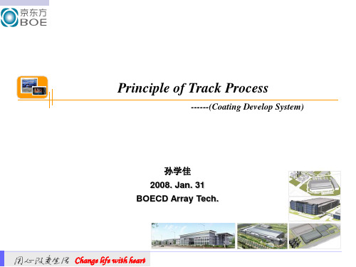
pattern,这个 pattern的作用就是保护在它下面薄膜,使其在
下一道刻蚀工序中不被刻蚀掉,从而最终在薄膜上形成我们所需 要的TFT pattern.
Coat & Exposure
Copyright BOE Technology Group
Development TFT Panel
Glass (After Thin Film)
‹#›
B2 Project Team
概述
3. 光刻与整个阵列的关系 3.1 光刻工序在整个阵列工序中起着承上启下的作用,它和其他两个阵 列工序一样,光刻工序使用5MASK(或4MASK)工艺处理玻璃基板 3.2 每次曝光形成一个层,共5(或4)层,最后叠加形成最终的TFT pattern 。
玻璃基板
Copyright BOE Technology Group
‹#›
B2 Project Team
概述
(2) 曝光Exposure
通过Mask的遮光作用,有选择性的将光刻胶感光,此过程通过曝 光机来实现
Exposure
mask
Copyright BOE Technology Group
‹#›
B2 Project Team
•
•
Copyright BOE Technology Group
‹#›
B2 Project Team
Bake
② Cooling Plate (CP):
• • CP用于对玻璃基板进行冷却处理 Cooling plate中采用冷却循环水进行热交 换,玻璃基板与plate之间距离为0.3mm, 采用热辐射的形式冷却。 玻璃基板进入CP后首先放臵于Lift pin(12 支)上,此时Lift pin处于待机位臵,一段 时间后Lift pin变换到Bottom位臵。 (急剧的温度变化会损伤玻璃基板) CP由冷却循环水进行温度调节。
基于涂层技术的薄壁止裂试验研究

Journal of Mechanical Strength2023,45(5):1103-1107DOI :10.16579/j.issn.1001.9669.2023.05.013∗20220302收到初稿,20220407收到修改稿㊂东北大学航空动力装备振动及控制教育部重点实验室研究基金项目(VCAME202102)资助㊂∗∗姜金德,男,1998年生,辽宁庄河人,汉族,沈阳建筑大学硕士研究生,主要研究方向为振动噪声控制㊂∗∗∗任云鹏(通信作者),男,1974年生,山东莱州人,汉族,沈阳建筑大学教授,硕士研究生导师,主要研究方向为参数化设计㊁振动噪声控制㊁装备设计与优化㊂基于涂层技术的薄壁止裂试验研究∗EXPERIMENTAL STUDY ON THIN WALL CRACK ARRESTBASED ON COATING TECHNOLOGY姜金德∗∗1㊀任云鹏∗∗∗1㊀卢崇劭2㊀朱清玉3㊀㊀张东旭2(1.沈阳建筑大学机械工程学院,沈阳110168)(2.沈阳智振科技有限公司,沈阳110000)(3.大连理工大学机械工程学院,大连116024)JIANG JinDe 1㊀REN YunPeng 1㊀LU ChongShao 2㊀ZHU QingYu 3㊀ZHANG DongXu 2(1.School of Mechanical Engineering ,Shenyang Jianzhu University ,Shenyang 110168,China )(2.Shenyang Intelligent Vibration Technology Co.,Ltd.,Shenyang 110000,China )(3.School of Mechanical Engineering ,Dalian University of Technology ,Dalian 116024,China )摘要㊀工程薄壁结构长期受到交变载荷作用,产生疲劳裂纹且多为贯穿性裂纹,进而导致修复困难和工程中不能替换问题,因此提出一种涂层技术对薄壁结构修复和止裂㊂制作与实际工程相关的薄板试验件,并预置裂纹㊂试验件在振动试验台做1阶弯曲共振状态和基础激励为10g 的激励试验,直至出现微裂纹㊂采用双面喷涂方法对试验件进行NiCrAl 涂层和NiCrAl 过渡层+ZrO 2功能层复合涂层两种涂层设置修复裂纹,并重复激励试验㊂对比试验件涂层前后的裂纹扩展时间和扩展速率,分析NiCrAl 涂层和ZrO 2涂层对带裂纹薄板试验件裂纹扩展的影响㊂验证涂层对薄壁板件的止裂效果㊂关键词㊀薄壁结构㊀涂层㊀裂纹修复㊀裂纹止裂㊀激励试验中图分类号㊀TG405Abstract ㊀Due to long-term alternating load,engineering thin-walled structures will produce fatigue cracks,and most ofthem are penetrative cracks,which will lead to difficult repair and irreplaceable problems in engineering.Therefore,a coatingtechnology is proposed to repair and crack arrest thin-walled structures.Thin plate test pieces related to practical engineering were made,and cracks were preset.The test piece was going to be subjected to the first-order bending resonance state and theexcitation test with the foundation excitation of 10g on the vibration test bench until cracks appear.Two kinds of coatings,NiCrAl coating and NiCrAl transition layer +ZrO 2functional layer composite coating,were applied to the test piece by double-sidedspraying method to repair the crack,and the excitation test was paring the crack propagation time and propagationrate of the test piece before and after coating,the influence of NiCrAl coating and ZrO 2coating on the crack propagation of the thin-walled plate test piece was analyzed.The crack arrest effect of the coating on the thin-walled plate is verified.Key words㊀Thin wall shell structure ;Coating ;Crack repair ;Coating crack arrest ;Excitation testCorresponding author :REN YunPeng ,E-mail :renyunpeng 9310@The project supported by the Key Laboratory of Vibration and Control of Aero-Propulsion System,Ministry of Education,Northeastern University(No.VCAME202102).Manuscript received 20220302,in revised form 20220407.0㊀引言㊀㊀裂纹缺陷大量地存在于材料和工程结构中,不仅降低了材料和工程结构的承载能力,最终使得服役产品的真实有效寿命大大缩短,这样不满足资源节约和循环经济所提出的要求㊂尤其对于含有微小裂纹损伤的高附加值机械装备的核心部件,修复裂纹损伤才能节省资源㊁能源,具有显著的经济效益[1-4]㊂㊀1104㊀机㊀㊀械㊀㊀强㊀㊀度2023年㊀传统裂纹修复根据断裂力学中对裂纹形成与扩展的研究,将止裂的方法分为降低裂纹尖端应力强度㊁降低裂纹尖端应力集中㊁引入压应力三种方法[5]㊂由于传统裂纹修复本身存在局限性,而工程薄壁结构裂纹产生多为贯穿性裂纹,导致修复困难,所以传统裂纹修复方式不适合薄壁结构,从而提出一种涂层技术对薄壁结构进行修复和止裂㊂众多学者从事涂层技术对裂纹修复和止裂的研究㊂CIZEK J M M D I 研究了冷喷涂㊁热喷涂及等离子喷涂三种层状沉积方式对低碳钢试样疲劳性能的影响,三种喷涂方式对疲劳相对寿命的提高幅度均达到200%以上[6]㊂CAVALIERE P 等[7]使用Ansys 分析纯镍冷喷雾颗粒与涂层裂纹关系,发现冷喷涂修复有助于增加裂缝结构的整体疲劳寿命,纯冷喷镍粒子在合适的温度和速度下的冲击可以改善涂层的性能㊂PETRÁKOVÁK 等[8]研究冷喷A357铝合金的机械性能,冷喷涂A357涂层的整体性能支持了冷喷涂的可行性,适用于结构维修㊂杜广煜等[9]研究电弧离子镀沉积NiCrAlY 涂层的阻尼性能,发现NiCrAlY 涂层能明显提高样品的阻尼性能㊂管宇等[10]在国内首次实现了冷喷涂增材技术在飞机关键主承力结构原位修复的工业级应用,解决了关键部位裂纹常规方法无法修理的核心技术难题㊂目前,热喷涂在薄板止裂方面的研究尚未见诸文献㊂本文提出采用等离子喷涂技术对薄壁结构修复和止裂,并进行试验验证涂层对薄壁板件的止裂效果㊂1㊀试验设备及步骤1.1㊀试验件制备㊀㊀选择厚度为6mm 的16Mn 钢板加工出2个试验件,编号分别为B1㊁B2㊂试验件长度为60mm,宽度为70mm;设计高30mm,厚20mm 的夹持区域㊂采用线切割的加工方式在距离夹持区高约15mm 处切割贯穿性沟槽,沟槽宽度为1mm,长度为30mm㊂采用等离子喷涂两种不同的涂层,分别涂覆B1㊁B2,涂层方式见表1㊂试验件涂层前后实物照片见图1㊂表1㊀不同试验件的涂层方式Tab.1㊀Coating methods of different test pieces编号Number涂层材料Coating materialB1双面:150μm NiCrAl 涂层Double sided:150μm NiCrAl coatingB2双面:60μm NiCrAl 过渡层+150μm ZrO 2功能层Double sided:60μm NiCrAl transition layer +150μm ZrO 2functional layer1.2㊀试验设备㊀㊀搭建振动试验系统,主要仪器设备见表2㊂图1㊀试验件涂层前后Fig.1㊀Before and after coating of test piece表2㊀系统组成的主要仪器设备Tab.2㊀Main components and instruments of the system名称Name 型号Model 主要性能参数Main performance parameters振动台Vibration tableES-10-240频率范围5~5000Hz Frequency range:5~5000Hz最大加速度1000gMaximum acceleration 1000g加速度传感器Acceleration sensorPCB-352C22灵敏度10mV /g Sensitivity 10mV /g频率响应13kHzFrequency response 13kHz应变片Strain gaugeBX120-3AA电阻值120Resistance value 120应变极限20000μm /m Strain limit 20000μm /m应变调理仪Strain conditioninginstrumentINV1861A8通道,标定值0.5mV /μ8channels,calibration value 0.5mV /μ频率响应DC-10kHzFrequency response DC-10kHz数据采集仪Data acquisition instrumentLMS SCADASIII8通道,采样率102.4kHz8channels,sampling rate 102.4kHz 支持多种输入模式Support multiple input modes数采分析软件Data acquisition analysis softwareLMS b在线生成时域波形㊁频谱㊁三维瀑布图等Online generation of time domain waveform,spectrum,three-dimensional waterfall,etc试验件振动测试现场如图2所示,试验件夹持方式及传感器布置方式如图3所示㊂通过螺栓连接的方式将试验件固定在夹具上形成悬臂结构形式㊂为了试验中获取试验件的固有频率,在其根部布置加速度传感器监测振动信号,在试验件危险部位布置应变片监测振动应力㊂1.3㊀试验步骤㊀㊀1)选取适当的频率范围,采用振动台扫频的方式获取试验件扫频时域信号,瀑布图峰值对应的频率点即为试验件的固有频率,如图4所示㊂2)根据应力分布结果确定了最大应力点为试验件根部位置,通过此位置的应变片进行了应力标定,根㊀第45卷第5期姜金德等:基于涂层技术的薄壁止裂试验研究1105㊀㊀图2㊀试验件振动测试现场Fig.2㊀Vibration test site of testpiece图3㊀试验件夹持方式及传感器布置方式Fig.3㊀Clamping mode of test piece and sensorlayout图4㊀扫频瀑布图Fig.4㊀Sweep waterfall diagram据标定结果进行振动试验㊂3)给定振动台的基础激励幅值为10g ,按照扫频得到的固有频率值对涂层前的试验件进行激振,试验过程中根据加速度传感器监测的共振响应变化的大小决定停机时间,通过扫频方式获取试验件新的固有频率并记录数据,再继续进行共振试验,直至试验件固有频率下降至原固有频率的85%以下㊂4)对做完振动试验的涂层前试验件进行涂层,再重复上述步骤,测试试验件涂覆涂层后裂纹扩展情况㊂2㊀试验结果与分析2.1㊀涂层前结果与分析㊀㊀给定振动台的基础激励幅值为10g ,按照扫频得到的固有频率值对试验件B1㊁B2进行激振,记录历经不同时间试验件的固有频率值,如表3所示㊂表3㊀试验件B1、B2固有频率随时间的变化Tab.3㊀Variation of natural frequencies oftest piece B1and B2with timeB1B2频率Frequency /Hz时间Time /min频率Frequency /Hz时间Time /min729.507300729.5307303071820716.5207091570415700.515694156901068510679.5106771067010668.510660566056525652.556445644.55635.55636.556273628.53619.53619.536122612260526052绘制试验件B1㊁B2的固有频率变化规律如图5所示㊂图5㊀试验件B1㊁B2涂层前固有频率随时间的变化Fig.5㊀Variation of natural frequency of test pieces B1and B2with timebefore coating从图5所示可以看出:试验件B1㊁B2固有频率随时间的变化曲线几乎重合,在共振基础激励下其1阶固有频率也经历了 缓慢下降-快速下降 的变化过程,说明裂纹扩展具有一定的规律性㊂以B2为例,从图5可以看出,B2初始固有频率为730Hz,对其施加定加速度10g 和定频730Hz 下的基础激励,经历30min 后,B2的固有频率仍为730Hz,说明薄板还未出现裂纹萌生㊂在该工况下继续激励20min 后,B2的固有频率下降到716.5Hz,说明薄板出现了裂纹萌生㊂对其施加定加速度10g 和定频716.5Hz 下的基础激励,15min 后,B2的㊀1106㊀机㊀㊀械㊀㊀强㊀㊀度2023年㊀固有频率下降到704Hz㊂为了完整地观察裂纹扩展现象,逐渐减少每次的共振时间,然后对其进行扫频获得固有频率;在经历了110min 后,B2的固有频率出现了陡降,说明薄板进入了裂纹扩展阶段;140min 后,B2的固有频率下降到605Hz,下降了17.1%㊂图6为试验件B2破坏后沿着缺口处产生的振动疲劳裂纹㊂图6㊀试验件B2裂纹Fig.6㊀B2crack of test piece2.2㊀涂层前后结果与分析㊀㊀采用等离子喷涂技术对薄板两侧喷涂金属涂层,B1双面喷涂150μm NiCrAl 涂层,B2双面喷涂60μmNiCrAl 过渡层+150μm ZrO 2功能层涂层;并开展涂层后的薄板振动试验,分析涂层材料对裂纹的止裂效果㊂1)B1涂层前后结果与分析同样给定振动台的基础激励幅值为10g ,按照扫频得到的固有频率值对试验件B1进行激振,记录历经不同时间试验件的固有频率值㊂图7为试验件B1涂层后测试现场㊂图7㊀涂层试验件B1测试现场Fig.7㊀Coating test piece B1test site试验件B1涂覆NiCrAl 涂层后,其固有频率随共振时间的变化如表4所示㊂表4㊀涂层试验件B1固有频率随时间的变化Tab.4㊀Variation of natural frequency of test piece B1with time频率Frequency /Hz 659.4659.4655.4650.8643.6时间Time /min 015101010频率Frequency /Hz 638.8635.5627.7621.4时间Time /min5555试验件B1涂层前后的固有频率随共振时间变化的趋势如图8所示㊂图8㊀试验件B1固有频率随时间的变化Fig.8㊀Variation of natural frequency of test piece B1with time从图8可以看出,试验件B1涂层前的固有频率经历了一个 缓慢下降-快速下降 的变化过程,初始固有频率729.5Hz 降到605Hz 经历了140min;在试验件B1两侧涂覆NiCrAl 涂层后,固有频率由605Hz 升高到659.4Hz,这是由于喷涂可以显著改善涂层性能,喷涂时纳米涂层填充了产生的孔隙和裂纹等缺陷,修复层与涂层之间的界面发生冶金结合,含有少量纳米粒子的细小颗粒存在于修复层中使晶粒细化,增加晶界数量并获得细晶组织,同时提高组织的致密化程度,增强了涂层内部和涂层-基体之间的结合强度,使得板的刚度增大,固有频率增大㊂涂覆NiCrAl 涂层后,薄板B1固有频率下降速率变慢,试验件B1涂层前固有频率从659.4Hz 下降到621.4Hz 需要约26min,涂层后需要约65min,时间提高了约2.5倍,说明涂层可以提高设备使用寿命,一方面由于NiCrAl 涂层修复了裂纹,阻止了裂纹扩展;另一方面NiCrAl 涂层具有高阻尼特性,可使共振应力降低,从而延长疲劳寿命㊂2)B2涂层前后结果与分析试验件B2涂覆NiCrAl +ZrO 2涂层后,其试验过程跟试验件B1涂层后试验过程一样,其固有频率随共振时间的变化如表5所示㊂表5㊀涂层试验件B2固有频率随时间的变化Tab.5㊀Variation of B2natural frequency of coatedtest piece with time频率Frequency /Hz 624624618.5617.5时间Time /min 05105频率Frequency /Hz 606596586时间Time /min553试验件B2涂层前后的固有频率随共振时间变化的趋势如图9所示㊂从图9可以看出,试验件B2两侧涂覆NiCrAl +ZrO 2涂层后,固有频率由605Hz 升高到624Hz,说明㊀第45卷第5期姜金德等:基于涂层技术的薄壁止裂试验研究1107㊀㊀图9㊀试验件B2固有频率随时间的变化Fig.9㊀Variation of natural frequency of test piece B2with time涂层可以改善薄板基体性能,喷涂时纳米涂层填充了产生的孔隙和裂纹等缺陷,使得板的刚度增大,固有频率增大㊂涂覆NiCrAl+ZrO2涂层后,试验件B2固有频率下降速率相对涂层前变慢,试验件B2涂层前固有频率从624Hz下降到605Hz需要约10min,涂层后需要约25min,时间提高了约2.5倍㊂2.3㊀涂层止裂效果对比㊀㊀试验件B1/B2涂层前固有频率随时间的变化曲线几乎重合;涂覆不同的涂层后,试验件B1的固有频率由605Hz升高到659.4Hz,试验件B2固有频率由605Hz升高到624Hz;试验件B1经历65min固有频率下降了5.7%,试验件B2经历33min固有频率下降了6.0%,试验件的B1固有频率下降速度相对试验件B2更慢㊂对比NiCrAl涂层和NiCrAl+ZrO2涂层止裂效果,初步判断NiCrAl涂层较ZrO2涂层具有更好的止裂效果㊂3㊀结论㊀㊀研究了试验件涂覆涂层前后的裂纹扩展特性,结果表明,涂层对抑制薄板裂纹扩展具有很好的效果,得到的主要结论有:1)通过预制裂纹薄板试验件的振动疲劳试验结果可知,随着振动循环时间增加,薄板裂纹长度进一步扩展,薄板裂纹的扩展速率逐渐增大,而且增长的越来越快,具有一定的规律性㊂2)涂层修复技术对裂纹具有较好的止裂效果,且对贯穿性裂纹具有一定的止裂效果㊂3)涂层修复裂纹后,薄板试验件固有频率发生快速下降的时间明显比涂层前的要长许多,可延缓试验件疲劳裂纹扩展,提高使用寿命㊂4)试验结果表明,NiCrAl涂层较ZrO2涂层具有更好的止裂效果㊂参考文献(References)[1]㊀蒋险峰.裂纹尖端的激光修复实验研究[D].大连:大连理工大学,2017:1.JIANG XianFeng.Experimental study on laser repair of crack tip[D].Dalian:Dalian University of Technology,2017:1(InChinese).[2]㊀TANG X S,SIH G C.Evaluation of microstructural parameters formicro/macro-line crack damage model[J].Theoretical&AppliedFracture Mechanics,2006,46(3):175-201.[3]㊀杨孚标.复合材料修复含中心裂纹铝合金板的静态与疲劳特性研究[D].长沙:国防科学技术大学,2006:1.YANG FuBiao.Study on static and fatigue characteristics ofaluminum alloy plate with central crack repaired by compositematerials[D].Changsha:National University of Defense Scienceand Technology,2006:1(In Chinese).[4]㊀DHAR S,SETHURAMAN R,DIXIT P M.A continuum damagemechanics model for void growth and micro crack initiation[J].Engineering Fracture Mechanics,1996,53(6):917-928. [5]㊀邓德伟,于㊀静,刘倩倩,等.裂纹止裂愈合技术发展现状及展望[J].机械工程学报,2016,52(7):122-132.DENG DeWei,YU Jing,LIU QianQian,et al.Development statusand prospect of crack arrest and healing technology[J].Journal ofMechanical Engineering,2016,52(7):122-132(In Chinese).[6]㊀CIZEK J M M D I.Influence of cold-sprayed,warm-sprayed,andplasma-sprayed layers deposition on fatigue properties of steelspecimens[J].Journal of Thermal Spray Technology,2015,24(5):758-768.[7]㊀CAVALIERE P,SILVELLO A.Finite element analyses of pure Nicold spray particles impact related to coating crack behaviour[J].Surface Engineering,2017:1-8.[8]㊀PETRÁKOVÁK,KONDÁS J,GUAGLIANO M.Mechanicalperformance of cold-sprayed A357aluminum alloy coatings for repairand additive manufacturing[J].Journal of Thermal SprayTechnology,2017,26(8):1888-1897.[9]㊀杜广煜,谭㊀祯,巴德纯,等.电弧离子镀制备NiCrAlY涂层及其阻尼性能[J].东北大学学报(自然科学版),2012,33(5):727-730.DU GuangYu,TAN Zhen,BA DeChun,et al.NiCrAlY coatingprepared by arc ion plating and its damping properties[J].Journalof Northeast University(Natural Science Edition),2012,33(5):727-730(In Chinese).[10]㊀管㊀宇,陈㊀亮,曹奇凯.基于增量考核的飞机延寿方法与应用[J].航空学报,2021,42(8):226-241.GUAN Yu,CHEN Liang,CAO QiKai.Method and application ofaircraft life extension based on incremental assessment[J].Journalof Aeronautics,2021,42(8):226-241(In Chinese).。
TenarisHydril Wedge 523 521 Connections Running Ma
I d M C o d e G d L 00384/4 / M a r c h 2020TenarisHydrilWedge 523® / 521® ConnectionsScopeThese guidelines apply specifically to the use of TenarisHydril Wedge 523® and Wedge 521® connections. This document should be used inconjunction with the TenarisHydril Running Manual, which is the main document applicable to the running of all TenarisHydril premium connections.Tenaris Field Service Representatives can modify these guidelines when circumstances dictate. Implementation will only occur if the representative deems themodification to be non-detrimental to product integrity. All modifications being explained and agreed with the client representative prior to implementation and fully documented in the running report.References.TenarisHydril Running Manual..Premium Connection Approved Thread Compounds FTD29356..Recommended guidelines for the field inspection of TenarisHydril connections, GDL31457..Wedge 521® Handling plugs TSH-BD-35.0002..Wedge 523®Handling Plugs TSH-BD-34.0002.1. Verify the appropriate thread compound is available.2. Refer to document FTD29356 for a list of compounds approved by Tenaris.3. Latest version of the specific Product Data Sheet can be obtained from the T enaris website. In case this is unavailable, request the data sheet from the local T echnical Sales representative or *********************************.Pre-Running1. Never move or handle pipe without the correct thread protectors securely in place.2. Ensure connections are clean and free of all debris and / or contaminants, cleaning methods employed should conform to the recommendations contained within the TenarisHydril Running Manual.3. Visually inspect threads and seal areas prior to running, ensuring no damage is evident.4. Verify the connections to be assembled are genuine TenarisHydril manufactured connections.5. Verify compatibility of the Wedge 523® / 521®connection with any accessories such as pup joints, cross overs, cement heads, etc.6. Verify material grade of all accessories ensuring compatibility with main string.7. On Dopeless® Technology connections check the condition of both pin and box coating ensuring no peeloff or degradation has occurred.I D M C o d e G D L 00384/4 / M a r c h 20208. Check availability of handling plugs, minimum of 3 to ensure efficiency of running process.9. Check the handling plugs are in good condition and fit correctly onto pipe.10. Check single joint elevators have sufficient clearance to slide over the box expanded area and seat against the handling plug.11. Check the handling plugs are genuine TenarisHydril threads.12. Verify handling plug number and maximum lift capacity.13. Never exceed the maximum lift capacity. 14. Ensure handling plug OD / weight is compatible with the pipe connections, Wedge 523® / 521® have limited same OD / weight interchange capability. 15. Refer to the TenarisHydril running manual for the care and use of handling / lift plugs.Inspection1. Inspection criteria for all Wedge Series 500™connections is as outlined in the Field Service Operative Guideline GDL31457.2. Pay particular attention to seal areas of Wedge 523® connection.3. Check box and pin for signs of mashes ordeformation caused during transportation / handling. 4. Ensure there are no gouges, tears or raised material on seal saver area of Wedge 523® connection.Wedge 523® ConfigurationNo make up band on Wedge 523®.I D M C o d e G D L 00384/4 / M a r c h 2020Wedge 521® ConfigurationNo metal to metal seal on Wedge 521®.BandThread Compound Application1. Apply a thin coating of thread compound on the full pin end only, threads, seal and pin nose, the thread form should be clearly visible.2. Do not apply running compound to the box end.3. Thread compound should be cleaned from the box if received ‘rig ready’.I D M C o d e G D L 00384/4 / M a r c h 2020Thread Lock ApplicationConnections must be clean and dry when applying thread lock.1. Thread lock should be applied to 50% of the threads at the back of the pin connection.2. Running compound should then be applied to the threads and seal at the back of the box connection.3. When assembling standard non Dopeless ®Technology connections with thread lock use standard non Dopeless ® Technology torque values.Wedge 523® / 521® Dopeless ® Technology1. Minor rust or discolouring of the pin connection can be removed with the use of a clean, dry rag ensuring the Dopeless ® Technology coating remains intact.2. Minor rust or discolouring of the box connection can be removed with the use of a non abrasiveplastic scouring pad and a clean, dry rag ensuring the Dopeless ® Technology coating remains intact.3. Dopeless ® Technology connections do not require the application of thread compound for make up.4. If for whatever reason dope has to be applied to Dopeless ® Technology connections, whether both pin and box are Dopeless ® Technology or when mixing a standard connection with Dopeless ® Technology, apply thread compound as below:I D M C o d e G D L 00384/4 / M a r c h2020non dopeleSS ® pin into dopeleSS ® Box.Apply a thin coating of thread compound on the full pin end, threads and pin nose. Also Dope the pin seal of Wedge 523®.dopeleSS ® pin into Standard Box.Apply a thin coating of thread compound on the pin end threads only..Do not dope pin seal or box connection.dopeleSS ® pin into dopeleSS ® Box.Apply a very thin layer of thread compound on the pin threads only.. Do not dope pin seal or box connection.Wedge 523® / 521® Dopeless®Technology Thread Lock1. Ideally when running a Dopeless® Technology string the connections to be thread locked should be the non Dopeless® Technology variant with the connections cleaned of thread compound and completely dried, then thread lock and dope applied as per page 7.2. When thread locking Dopeless® Technology connections remove the Dopeless® T echnology coating from the threads on the pin connection where the thread lock is to be applied prior to the application of thread lock.3. Use a hand or rotary brass wire wheel to remove the Dopeless® Technology coating from the threads, ensuring no contact is made with the seal.4. Leave the Dopeless® Technology coating on the pin seal and threads where no thread lock is to be applied.5. Dopeless® Technology boxes should be washed with hot water then dried prior to thread locking.6. Thread lock should be applied to 50% of the pin threads furthest from the pin nose as per the diagram on page7.7. The application of thread compound is not required.8. Do not apply thread lock to the seal area. Torque Application1. Set tong dump valve at optimum torque then test on pipe body.2. For Dopeless® T echnology connections apply the specified torques as indicated on the T enarisHydrilDopeless® T echnology data sheet.I D M C o d e G D L 00384/4 / M a r c h 20203. For doped connections, apply the specified torques indicated on the T enarisHydril standard variant data sheet.4. Do not apply thread compound manufacturer’s friction factor.5. Standard doped variant, first connection make up;.Once optimum torque has been attained relax the tong and re-apply optimum torque..If movement over ½” is witnessed re-apply optimum torque +20%..Repeat process, checking to ensure no other factors areabsorbing the applied torque..Often the issue is caused by excessive application of thread compound..Continue making up further joints applying higher torque if required..Refer to the TenarisHydril Running Manual torqueapplication section.6. Double bump, (as above) every connection with an OD of 10 ¾” or larger.7. For Dopeless ® Technology connections applying optimum torque twice (double bump) is not necessary.8. When any doped variant is made up to a Dopeless ® Technology connection apply the doped variant torque values. Double bump the connection as point 5. 9. When applying thread lock to standard doped connections, doped version torque values +20% should be used then double bump the connection.10. When applying thread lock to Dopeless ®Technology connections, Dopeless ® Technology torque values +20% should be used then double bump the connection.11. Computer make up equipment is not mandatory for Wedge 523® / 521® connections in carbon steel, but is recommended.12. Computer make up equipment is stronglyrecommended for Wedge 523® / 521® connections in chrome steel.13. Graph analysis for Wedge 523® / 521® connections is similar to that for all Wedge Series 500™, refer to the TenarisHydril Running Manual make up acceptance section for further explanation.14. When computer equipment is used to monitor connection make up, the graph profiles should be similar to the one below.15. Wedge 523® connection has limited same size /weight interchange capability, if mixing weight / grade ensure compatibility of design and apply the higher torque value of the two connections.I DM C o d e G D L 00384/4 / M a r c h 202016. Wedge 521® connection has limited same size / weight interchange capability, if mixing weight / grade ensure compatibility of design and apply the higher torque value of the two connections.17. Wedge 521® and Wedge 523® connections are not interchangeable.18. Wedge 523® and 513® connections arecompatible in the same size / weight combination. For other weight combinations check the TenarisHydril premium connections catalogue.19. When correctly assembled, Wedge 521®connection box face should finish within the make up band lines.Wedge 521® Make Up BandRunning1. The use of a stabbing guide is strongly recommended.2. The use of slip type elevators are recommended.3. The use of a safety clamp is strongly recommended when running Wedge 523® / 521® connections.4. The use of a weight compensator is stronglyrecommended for chrome, large OD or heavy weight pipe.5. To avoid cross threading, stab pipe in a smooth controlled fashion ensuring the pipe is vertical when doing so, continue to support and stabilise the pipe throughout the make up operation.6. Upon commencement of initial rotation use low RPM (5 RPM or below) in order to ensure the pipe has not cross threaded during stabbing.7. If cross threading is evident, immediately reverse rotate the pipe, completely disassemble, clean and inspect both connections.8. Maximum assembly speeds are indicated in the tables below. These are applicable for running in singles with tong or CRT and assuming ideal conditions.9. Conditions may dictate lower assembly speeds than the maximums indicated. High winds or excessive pipe movement among other variables will necessitate a lower RPM to be used.I D M C o d e G D L 00384/4 / M a r c h 202010. Do not exceed 15 RPM during spin in.11. Walk chrome pipe all the way in to hand tight, then apply tong only for final make up.12. Ensure the back up tong is located below the box upset to prevent damage.13. A factor which may preclude complete assembly is excessive thread compound applied to the connection, reduce the quantity applied if this is found to be the case.Pulling1. The use of a stabbing guide is strongly recommended to prevent hang up.2. The use of slip type elevators is strongly recommended.3. A single joint compensator is strongly recommended for chrome, large OD or heavy pipe.4. The use of a safety clamp is strongly recommended.5. Apply the back up tong jaw well below the box.6. Apply power tong in low RPM (3-5 RPM) to break out the connection, ensuring the pipe is stabilised during the break out process.7. Do not exceed 15 RPM during spin out.8. Walk chrome pipe all the way out by hand after initial break out.9. Visual inspection is recommended to classify the thread condition, any rejected connections should be clearly marked and segregated for further investigation.10. Apply clean, dry thread protectors after applying storage compound on clean, dry connections.11. Storage / thread compound should always be applied to connections post job, even rejects.12. Do not apply storage compound to Dopeless®Technology connections.13. For long term storage of Dopeless® Technology connections, refurbishment by qualified personnel is recommended.14. Ensure clean, dry, Dopeless® Technology protectors with seal rings correctly in place are installed.Tenaris has produced this manual for general information only. While every effort has been made to ensure the accuracy of the information contained within this publication, Tenaris does not assume any responsibility or liability for any loss, damage, injury resulting from the use of information and data herein. Tenaris products and services are only subject to the Company’s standard terms and Conditionsor otherwise to the terms resulting from the respective contracts of sale, services or license, as the case may be. The information in this publication is subject to change or modification without notice. For more complete information please contact a Tenaris’s representative or visit our website at .This manual supersedes Version 03 / March 2018. ©Tenaris 2020. all rights reserved.。
模具镀层知识点总结
模具镀层知识点总结一、模具镀层的分类1. 金属镀层:主要包括电镀、热浸镀、喷涂等方法。
金属镀层可以有效提高模具的抗磨性和抗腐蚀性,常用的金属包括镍、铬、钛等。
2. 非金属镀层:如化学镀、喷涂等方法。
非金属镀层通常用于提高模具的耐蚀性和抗磨性,常用的非金属包括氮化物、氧化物、碳化物等。
二、模具镀层的优点1. 提高表面硬度:模具经过镀层处理后,表面硬度能够得到有效提高,提高了模具的耐磨性和抗压性。
2. 延长使用寿命:模具表面的镀层能够有效延长模具的使用寿命,减少更换和修理的次数,降低了生产成本。
3. 提高表面质量:模具经过镀层处理后,表面光洁度和精度得到了有效提高,提高了产品的质量。
4. 降低摩擦力:模具表面的镀层能够减少摩擦力,提高了模具的使用效率。
5. 提高产品精度:模具经过镀层处理后,能够提高产品的尺寸精度和表面质量,提高了产品的质量和市场竞争力。
6. 降低生产成本:镀层处理能够延长模具的使用寿命,减少了更换和修理的次数,降低了生产成本。
三、模具镀层的常见方法1. 电镀:电镀是最常见的模具镀层方法,采用电化学方法,在模具表面沉积一层金属或非金属覆盖层,形成均匀的镀层。
电镀方法有镀铬、镀镍、电镀铜、电镀锌、电镀银等。
2. 热浸镀:热浸镀是将模具浸入加热的液态金属溶液中,通过表面张力和元素扩散等过程,使金属沉积在模具表面形成均匀致密的镀层。
3. 喷涂:喷涂是将金属或非金属粉末通过喷枪喷洒到模具表面,然后进行烧结或烘干,形成均匀的镀层。
4. 化学镀:化学镀是利用化学还原或化学气相沉积等方法,在模具表面沉积一层金属或非金属镀层,形成均匀致密的镀层。
四、模具镀层的选材原则1. 选择合适的镀层厚度:镀层的厚度是影响模具使用寿命的重要因素之一,一般来说,金属镀层的厚度在几微米到几十微米之间,非金属镀层的厚度在0.1mm以下。
2. 根据使用条件选择镀层材料:根据模具的使用条件和要求,选择合适的镀层材料,如模具需要具有较高的表面硬度和耐磨性,选择具有高硬度的金属材料进行镀层,如需要具有较好的耐蚀性和氧化性,选择具有良好防腐蚀性能的材料进行镀层。
Surface & Coatings Technology
A novel surface activation method for Ni/Au electroless plating of acrylonitrile –butadiene –styreneXuejiao Tang a ,⁎,Jingang Wang b ,Chengjun Wang c ,Boxiong Shen aa College of Environmental Science &Engineering,Nankai University,Tianjin,300071,PR Chinab Engineering Research Center of Seawater Utilization Technology,Ministry of Education,Hebei University of Technology,Tianjin,300130,PR China cCollege of Chemistry and Materials Engineering,Wenzhou University,Wenzhou,Zhejiang,325035,PR Chinaa b s t r a c ta r t i c l e i n f o Article history:Received 18November 2010Accepted in revised form 31August 2011Available online xxxxKeywords:Surface activation AutocatalysisNon-cyanide electroless plating Interfacial reactionDirect electroless metallization on acrylonitrile –butadiene –styrene (ABS)plastic with Pd-free activation method could reduce the cost of production.A novel surface activation method with the immobilization of Ni(0)nanoparticles by chitosan (CTS)film on ABS and then the deposition of Ni and Au on ABS were inves-tigated in this paper.X-ray photoelectron spectroscopy (XPS),fourier transform infrared (FTIR)spectra and scanning electron microscopy (SEM)data revealed the related interfacial reaction mechanism in activation process.The Ni(0)nanoparticles immobilized by the CTS films were effective auto-catalysts in the nickel elec-troless plating process.The formations of Ni plating layers at different deposition time were observed by SEM.The x-ray diffraction (XRD)patterns revealed the Ni layer at 30min was in an amorphous phase.Au was suc-cessfully plated on the Ni layers in a new,stable non-cyanide Au electroless plating bath with different reduc-ing agents.The chemical compositions of Ni/Au layers were analyzed by inductive couple plasmas (ICP)and ion chromatography (IC)measurements.Inorganic element (P or S)from reducing agents made the surface morphology of Au layers different in SEM images.However,they did not change the Au crystallization phase at all based on XRD patterns.©2011Elsevier B.V.All rights reserved.1.IntroductionThe engineering plastics have vast applications in electronic products.Demands for direct metallization on non-conducting plastics have been vigorously increasing.In electroless plating,metallization can be carried out evenly on non-conducting substrates.Electroless plating is consid-ered the most effective and promising metallization method.The immobilization of catalysts for the activation procedure plays an important role in metal electroless plating.The catalysts promote the oxidation of the reducing agent in the plating bath to initiate metal de-position onto the substrate.This step is the key point and can directly affect the quality of the plating layers.Many methods for activating non-conducting substrates have been developed [1–6].A classic one is the sensitization –activation method,wherein substrates are dipped in stannous chloride and palladium chloride solution.Metal-lic palladium [Pd(0)]clusters form on the surface and catalyze the subsequent electroless plating [7,8].However,Pd(0)catalysts are mainly immobilized on the substrate surface by physical plex processes and excessive noble metal waste add to this problem.Over the last few years,many studies have been devoted to methods of Pd(0)particle deposition such as spinning-on,spraying,or dip-coating of organopalladium and inducing decompo-sition of them by ultraviolet –visible light,infrared,or laser [9–11].Direct electroless metallization of an insulating substrate (polymers,glasses,or ceramics)without first seeding the surface with Pd(0)catalytic clusters is an interesting challenge.Such a technique will reduce the cost of the metallization process.Nickel (Ni),which is relatively less expensive than noble metals,was used as auto-catalysts for Ni electroless plating in our previous studies.The successful results simultaneously resolved problems of conventional activation methods (such as complex processes and excessive noble metal wastage).It was also found that CTS films had a good prospect for immobilizing Ni catalysts onto the ABS substrate in the activation process for nickel electroless plating.These findings were very interest-ing and published in short and quick communications [12,13].However,systematical work is required for reproducibility and the interfacial reac-tion mechanism needs to be veri fied by other analytical tools.Further-more,it is an interesting topic to observe the morphology of Ni layers at different deposition time and investigate the formation of Ni layers.The deposition of Au on Ni layers was widely used in electronic products industry.Cyanide gold electroless plating on a Ni-plating layer has long been utilized for the surface interconnection of electronic products.Considering safety and environmental concerns,cyanide-free plating is a better choice and is strongly in demand now.Thiosulfate is one of the best ligand candidates,with its high stability constant and strong chemical bonding force.It may be able to replace cyanide withSurface &Coatings Technology xxx (2011)xxx –xxx⁎Corresponding author.Tel.:+862223503219;fax:+862223508807.E-mail address:tangxuejiao@ (X.Tang).SCT-17024;No of Pages 70257-8972/$–see front matter ©2011Elsevier B.V.All rights reserved.doi:10.1016/j.surfcoat.2011.08.064Contents lists available at SciVerse ScienceDirectSurface &Coatings Technologyj o u r n a l h o m e p a ge :w w w.e l s e v i e r.c o m/l o c a t e /s u r f c o a tthe assistance of other stabilizers.However,the stability constant of Au (I)thiosulfate complexes is in the order1026,which is still1010times less than that of Au(I)cyanide complexes(1036)[14].Inoue et al.[15] developed stable non-cyanide electroless gold(Au)plating baths using thiosulfate as the primary ligand,sulfite as the secondary ligand, thiourea as the reducing agent,and hydroquinone as the reducing agent regenerator.Although a soft,good quality Au layer was obtained, one of the stabilizers used(hydroquinone)is also a toxic compound.To avoid such toxic compounds,a new and safe non-cyanide elec-troless Au plating bath was proposed in the present study.This plat-ing bath was also used to study the effects of reducing agents on the Au plating layer.Monovalent Au ion(gold source)was stabilized by thiosulfate and sulfite ligands,instead of the conventional toxic cy-anide.Sodium hypophosphite(NaH2PO2)was used as the reducing agent and sodium citrate as the stabilizer.The Au deposition immedi-ately started when the Ni-plating ABS foil was dipped into the new Au plating bath.The immobilization of Ni as catalyst sites by CTSfilm formed on the ABS for Ni electroless deposition was studied.The for-mation of Ni/Au electroless plating layers was observed by scanning electron microscopy(SEM).The components on the substrate surface after etching and activation were investigated by x-ray photoelectron spectroscopy(XPS),and the related interfacial reaction mechanism was discussed.The phase structures of the obtained Ni and Au layers were characterized by x-ray diffraction(XRD).2.Materials and methods2.1.MaterialsChitosan(CTS;deacetyl degree~92%)was purchased as industrial grade powder from Xiamen Sanland Chemical Agents,Ltd.All other chemicals used were of analytical grade.2.2.Methods2.2.1.Pretreatment procedures:etching and activatingAn etching procedure was employed to make the ABS foil surfaces rough and hydrophilic.Traditionally,heavily polluting coarsing solu-tions,such as chromium-based ones,are used.In the present study, the etching was performed by dipping the foils in a mixed solution of1:4hydrogen peroxide(H2O2;30%)and sulfuric acid(H2SO4; 98%)at room temperature[16].The effects of etching time on ABS morphology were studied,and5min was chosen as the most optimal for the procedure.After rinsing,the etched foils were dipped into1%acetic acid so-lution containing15g/L CTS for5min at room temperature,and were then dried at60°C for15min.These foils were denoted as ABS–CTS.The ABS–CTS foils were immersed in nickel sulfate solution (NiSO4∙6H2O;2.0g/L)at40°C for10min.After rinsing,the foils were dipped in a solution of potassium borohydride(KBH4;3.0g/L) at40°C for5min of reduction.ABS–CTS–Ni was then obtained.A comparative study without the CTSfilm formation procedure was also carried out.The etched foils were directly dipped into the nickel sulfate solution,and were then reduced by KBH4under the same condi-tions as above.The obtained sample was denoted as ABS–Ni.2.2.2.Electroless platingThe electroless Ni plating was achieved by dipping the pre-nucleated foils(ABS–CTS–Ni and ABS–Ni)into a solution containing sodium cit-rate(as chelating agent),sodium hypophosphite(as reducing agent), triethanolamine(as masking agent),ammonium chloride(as buffer), and coumarin(as stabilizer).The composition and deposition condi-tions of the NiP plating solution are given in Table1.The electroless Au deposition was achieved by dipping the rinsed Ni-plating ABS foils into a solution containing thiosulfate and sulfite ligands(as chelating agents),sodium hypophosphite(as reducing agent),and sodium citrate(as stabilizer).The stable non-cyanide gold plating solution is shown in Table2,and the obtained Au plating layer was denoted as Au–P.Another set of Ni-plated ABS foils were dipped into another Au electroless plating solution in which sodium hypophosphite was replaced with thiourea as the reducing reagent. The corresponding layer was denoted as Au–S.Both of the deposition times were15min.2.2.3.Surface characterizationThe chemical compositions of the foil surfaces and the chemical reactions during the pretreatment procedure(etching and activating) were investigated by XPS and specular reflection Fourier transforma-tion infrared(FTIR)spectroscopy.XPS spectra were recorded using a Kratos Axis Ultra DLD spec-trometer(UK)and employed with a monochromated Al-Kαx-ray source(hv=1486.6eV),hybrid(magnetic/electrostatic)optics,as well as a multi-channel plate and delay line detector.Specular reflection FTIR spectra were recorded with a Nicolet MAGNA-560FT-IR spectrometer(USA)with a reflection angle of30°.The surface topographies of the etched ABS and the different layers were characterized with a scanning electron microscope(SEM:SS-550, Shimadzu Corporation,Kyoto,Japan)at an accelerating voltage of10kV, using the secondary electron signal.The working distances are respec-tively shown in SEM surface micrographs(Figs.3–6).XRD measurements of the deposited layers were made with a Rigaku D/max-250018KW powder diffractometer(Japan)using Cu-Kαradia-tion generated at40kV and100mA,and a scanning rate of0.13deg/s.Chemical composition analysis of the deposited layers was performed on an ICP-9000instrument(U.S.A.Thermo Jarrell-Ash Corporation)and DX-500ion chromatograph(U.S.A.Dionex Corporation)equipped witha suppressed anion conductivity detector and IonPac AS20column.3.Results and discussion3.1.XPSThe XPS spectra of CTS,etched ABS,and ABS–CTS–Ni are shown in Fig.1a–d.As shown in Fig.1a,the S2p3/2photoelectron spectrum peak was observed at a binding energy of168.7eV for etched ABS.This peak corresponds to the peak position of H–O–S(O2)–C6H4[17]and was different from those of NiSO4(169.2eV)[18]and H2SO4(169.6eV) [19].The sulfonic acid group[H\O\S(O2)\C6H4\]was introduced by the electrophilic aromatic substitution reaction of the phenyl ring from the ABS substrate during the etching treatment in H2SO4so-lution.The etching time was very short to avoid over-roughness.The chemical reaction occurred only with the functional group on the top surface of ABS.The signal intensity of the H\O\S(O2)\C6H4\bond was not strong enough,and the other small peaks in Fig.1a corre-spond to background noise.Drying the CTSfilm on the ABS surface at60°C promoted the reac-tion between the sulfonic acid group and the amino groups(\NH2)of CTS.New and stable\NH\S(O2)\C6H4\(S2p3/2absorption peak at a binding energy of167.6eV for ABS–CTS–Ni;Fig.1b)functional groupsTable1Composition and plating condition of nickel electroless plating solution.Component Concentration(g/L)Ni2+6Sodium hypophosphite23Sodium citrate20Triethanolamine22Ammonium chloride15Coumarin0.03T40±2°CpH8.5–9.52X.Tang et al./Surface&Coatings Technology xxx(2011)xxx–xxxformed.This formation indicated that the etching process could modify the ABS surface from hydrophobic to hydrophilic.This formation also enhanced the adhesive strength between the CTS film and the ABS sub-strate through chemical reactions of their functional groups.The N 1s spectrum absorption peak in ABS –CTS –Ni (407.5eV;Fig.1c)was 8.3eV higher than that of \NH 2in CTS (399.2eV [20]).Chemical shifts of binding energies in XPS are a displacement effect in the spectrum absorption peaks,which results from changes in the electron binding energy of atoms in different chemical states [21].This result indicates that Ni bonded with the isolated electrons of the nitrogen atom.This binding caused the decreased thickness of the electron clouds around nitrogen atoms and consequently shifted the binding energy higher.Therefore,Ni could be successfully immobilized on CTS films with higher adhesive strength by chemical rather than physical adsorption.In Fig.1d,two Ni species peaks of Ni 2p3/2appeared in the XPS of ABS –CTS –Ni.The lower peak (at a binding energy of 852.8eV)corre-sponded to the Ni 2p3/2peak of Ni [22].The higher peak (at a binding energy of 857.8eV)corresponded to the Ni 2p3/2peak of NiSO 4[23].These results indicate that metallic nickel [Ni(0)]successfully formed on the ABS –CTS –Ni after being reduced by KBH 4.3.2.Specular re flection FTIRThe ABS foils were too hard and thick to be made as thin as a KBr tablet,so traditional transmission infrared spectroscopy was unsuitablefor the structural analysis of the ABS surface.Specular re flection FTIR can overcome the limitations of traditional transmission infrared.Spec-ular re flection FTIR spectra mainly reveal information from the surface of the samples.The FTIR spectra of the unetched ABS,etched ABS,ABS –CTS,ABS –CTS –Ni,ABS –Ni,and CTS are shown in Fig.2.The reactions that occurred during the pretreatment procedure were investigated.ABS is a copolymer of acrylonitrile,butadiene,and styrene.Hence,the spectra of unetched ABS correspond to these three components.As shown in Fig.2a,four peaks observed at 1600–1450cm −1,the peaks at 712and 3035cm −1are all characteristic adsorption spectra of the phenyl ring [24,25]in styrene.The peaks at 2946and 2862cm −1are characteristic of the methylene groups of acrylonitrile and butadiene.The strong peak at 962cm −1is characteristic of poly-butadiene [26].In Fig.2b,the wider and stronger peak at 3400–2000cm −1is the overlapping peaks of O –H and S –O.The peak appearing at 1381cm −1is characteristic of sulfonic acid groups.The weakening of the phenyl ring peak at 1600–1450and at 712cm −1is also observed in Fig.2b.These are all in agreement with the results of the XPS analysis that H –O –S(O 2)–C 6H 4–and –OH were formed on the ABS surfaces by the etching procedure.An electrophilic aromatic substitution reaction of the phenyl ring on the ABS surface occurred in the H 2SO 4solution.In Fig.2b,the signals at high wavenumbers were noisier because the surfaces were rougher in the etched than in the unetched ABS.Hence,the coarsing process is proven effective.As mentioned above,specular re flection FTIR spectra mainly re-veal information on the surface of the samples.The characteristic ad-sorption spectrum of the CTS film in Fig.2c is stronger and it encompasses the spectrum of the ABS substrate.Thus,the spectrum of ABS –CTS (Fig.2c)was obviously different from that of etched ABS (Fig.2b).Fig.2c shows the wide absorption peak at 3400–3200cm −1,which is the overlapping peak of O –H and N –H in the CTS film.The peaks at 3530and 1599cm −1are the adsorption spec-tra of N –H in CTS.The peak at 1435cm −1is that of C –N in CTS.The primary hydroxyl group peak of CTS is at 1037cm −1.All these peaks in Fig.2c are in agreement with the ones in CTS (Fig.2f),except here,the peaks at 1180–1100cm −1are stronger than those in CTS,Table 2Composition and plating condition of gold electroless plating ponentConcentration(g/L)Gold chloride4.5Sodium thiosulfate 11.2Sodium sul fite100.0Sodium hypophosphite 10.0Sodium citrate 50.0T 80±2°C pH7.8–8.0I n t e ns i t yI n t e n s i t yBinding Energy (eV)Binding Energy (eV)Fig.1.XPS spectra of S 2p3/2photoelectron on the etched ABS surface (a)and S 2p3/2photoelectron on ABS –CTS –Ni surface (b)and N 1s photoelectron on ABS –CTS –Ni surface(c)and Ni 2p3/2photoelectron on ABS –CTS –Ni surface (d).3X.Tang et al./Surface &Coatings Technology xxx (2011)xxx –xxxdue to the S –N and sulfonic esters.Again,\NH \S(O 2)\C 6H 4\group formation in ABS –CTS was con firmed.Compared with the ABS –CTS spectra (Fig.2c),the peaks of N –H (1599cm −1)and C –N (1434cm −1)in the ABS –CTS –Ni (Fig.2d)spectra both became weaker.The N –H peaks shifted from 3530to 3480cm −1.Ni was already chemically chelated by the \NH 2group in the CTS film,which corresponded to the XPS results.The adsorp-tion of the primary hydroxyl group at 1037cm −1intensi fied in ABS –CTS –Ni.Involvement of primary hydroxyl groups in the com-plexation of Ni,as suggested above,corresponds to that of previous studies [27,28].Moreover,the formation of hydrogen bonds could also cause the blue shifting of the N –H and O –H peaks.To con firm the importance of the CTS film in the pretreatment procedure,a comparative study without CTS film formation was per-formed.Specular re flection FTIR spectra of the ABS –Ni (Fig.2e)show that the shape of the ABS –Ni spectrum was almost the same as that of etched ABS (Fig.2b).It was indicated that Ni was not adsorbed ontothe etched ABS surface and the chemical reaction did not occur be-tween Ni and the etched ABS.Therefore,CTS is very important for immobilizing the Ni catalysts onto the ABS surface.3.3.SEMFor further investigation,SEM characterization was used to inves-tigate the effect of etching time on ABS morphology.The SEM micro-graphs of unetched ABS,as well as ABS etched for 5,7,9,and 11min are shown in Fig.3a –e.As shown in Fig.3,etching time signi ficantly affects ABS surface morphology.The coarseness of the ABS surface is greatly increased with increasing etching time.Appropriate roughness strengthens the adhesion between the CTS film and ABS (Fig.3b),whereas over-roughing (caused by longer etching times)is not good and may even destroy the ABS substrate (Fig.3e).The etching time of 5min was chosen as most appropriate.To observe the formation process of the Ni/Au layers,the appear-ances of ABS –CTS and ABS –CTS –Ni with different plating times,as well as the topographies of Au layers were characterized by SEM (Fig.4a –e).Fig.4a shows an even and continuous CTS film formed on the ABS surface after treatment with the CTS solution.Fig.4b shows uniform nanosized particles evenly adsorbed onto the CTS film.Based on the XPS data of ABS –CTS –Ni,these particles are a mixture of Ni(0)nano-particles and NiSO 4crystals.Remnants of unreduced NiSO 4had no ef-fect on the subsequent electroless plating.The auto-catalysts Ni(0),obtained by KBH 4reduction,were capable of initiating the Ni electro-less plating.Ni deposition was achieved by dipping ABS –CTS –Ni foils into the Ni plating solution.The appearances of the substrate surface on which electroless Ni plating lasted for 2,5,and 30min are also shown in Fig.4c –e.Fig.4c shows spherical Ni(0)cores on the CTS film (at 2min of plating)bigger than those in Fig.4b.The cores were formed by the catalytic reduction of Ni ion from the electroless plating solution with Ni(0)particles as effective catalyst sites [27].The SEM micro-graph of Ni deposition at 5min (Fig.4d)shows that the Ni atoms4000350030002500200015001000500Wave Number / cm-1ab c d T r a n s m i t t a n c e /%ef Fig.2.FTIR spectra of the surfaces of unetched ABS (a)and etched ABS (b)and ABS –CTS (c)and ABS –CTS –Ni (d)and ABS –Ni (e)and CTS (f).Fig.3.SEM photographs of ABS with different etching times.(a)0min (unetched),(b)5min,(c)7min,(d)9min,and (e)11min.4X.Tang et al./Surface &Coatings Technology xxx (2011)xxx –xxxnucleated and gradually clustered on the ridges of the Ni cores.With longer deposition times,the Ni atoms covered the Ni spheres rather than generated new nucleation sites on the CTS film.Thus,the Ni spheres grew in size and coalesced to form larger clusters [29].The rate of substance transfer during this period was controlled by the surface reaction of the Ni catalytic reduction.When Ni deposition lasted for 30min,a Ni plating player was obtained (Fig.4e).The aver-age thickness of Ni layer at depositon time of 30min was 7.2μm from weight increase.The SEM micrograph of ABS –Ni (Fig.5)shows no Ni particle on the ABS –Ni surface.As discussed in Section 3.2.,Ni(0)was not adsorbed onto the etched ABS surface because Ni 2+was only physically adsorbed and easily rinsed off.This weak adsorption could be slightly improved if the rinsing process is omitted after dipping the etched ABS foils in the Ni solution.However,the KBH 4solution would be very easily exhausted because of the excess Ni 2+on the surface.This would be a big waste of resources and would increase the production cost,and the adhesion of Ni(0)onto the ABS surface would still be insuf ficient.In summary,CTS film formation plays an important role in the pretreatment proce-dure.The CTS film highly enhanced the adherence of metal catalysts onto the substrate by chemical adsorption for the subsequent electro-less plating.The Au –P layer of average 0.05μm thickness and Au-S layer of 0.07μm were obtained.Different inorganic element(P or S)was pre-sent in Au layers due to different reducing agent in Au plating bath.The metals on top surface (thickness b 5.0μm)of layers on ABS were sampled and nitri fied.The water-soluble ions were analyzed by ICP and IC measurement to evaluate the chemical compositions.Element contents in the layers were shown in Table 3.The data for Au –S/Ni –P in Table 3indicated that S was present in Au –S layer.The relative P content to Ni (P:Ni)for Au –P/Ni –P was 0.068,higher than P:Ni in Ni –P indicating P was present in Au –P.Different inorganic element present in Au layers might affect the properties of Au layers.The SEM photographs of the Au –P and Au –S layers (Fig.6)show uniformly sized and shaped Au particles in both layers.However,the shape of Au grains in Au –P is apparently differ-ent from that in Au –S.The former are bar-shaped and the latter are round (Fig.6).The distinct surface topographies of Au –P and Au –S layers suggested that element P (or S)affect the surface morphology of Au layers and changed the growth of Au grains considerably.3.4.XRDThe XRD pattern of the Ni plating layer deposited for 30min is presented in Fig.7.A broad diffraction peak is observed at around 45°,which originates from the Ni electroless plating layer.The XRD results clearly reveal that the Ni layer was in an amorphous state [30,31].Fig.8shows that the XRD pattern of Au –S is in accord with that of Au –P.No peak shifts or broadening was observed.ThecrystallizationFig.4.SEM photographs of surfaces of ABS –CTS (a)and ABS –CTS –Ni (b)and Ni deposition at 2min (c)and Ni deposition at 5min (d)and Ni deposition at 30min(e).Fig.5.SEM photographs of ABS –Ni surface.Table 3Chemical compositions of layers of Ni –P,Au –P/Ni –P and Au –S/Ni –P.Element content (wt%)Ni Au P S P:Ni Ni –P93.5– 6.1–0.065Au –P/Ni –P 85.48.3 5.8–0.068Au –S/Ni –P88.06.05.60.240.0645X.Tang et al./Surface &Coatings Technology xxx (2011)xxx –xxxstate of the Au layer did not change despite the presence of elemental P (or S).4.ConclusionsNi/Au electroless plating on ABS was successfully carried out using a palladium-free surface activation method.XPS data revealed sulfonic acid group [H \O \S(O 2)\C 6H 4\]and \OH formation on the ABS sur-face in the etching procedure.The etching time signi ficantly affected ABS surface morphology.5min was chosen for etching procedure.Theimmobilization of auto-catalyst Ni(0)nanoparticles onto etched ABS in activation process was carried out through chemical adsorption by CTS film.FTIR spectra veri fied that the new activation method enhanced the adhesion between the CTS film and ABS foil by [\NH \S(O 2)\C 6H 4\]formation on the interfacial surfaces.XPS and FTIR indicated that Ni(0)nanoparticles were immobilized through \NH 2chelation and complexation of the primary CTS hydroxyl groups.FTIR and SEM in-dicated no chemical adsorption between Ni and the etched ABS in the ABS –Ni.Ni was easily rinsed off con firming the importance of CTS pre-treatment.A Ni –P plating layer was successfully obtained from an elec-troless Ni plating bath using the novel activation method.Au layers were obtained on top of Ni layers with a new,stable non-cyanide elec-troless Au plating.Different inorganic elements present in the Au layers changed the surface morphology but not the crystallization phase of Au layers.How the inorganic element (P or S)exists in Au layers will be an interesting future topic.This environmentally friendly Ni/Au electroless plating on ABS process with cost-effective activation method is promis-ing for large-scale manufacturing.AcknowledgmentsThe authors gratefully acknowledge financial support by the spe-cial fund for basic research of central colleges and universities in China (65010451),the National Natural Science Foundation of China (NSFC 50976050)and the Key Special Technologies R&D Program of Tianjin (09ZCKFSH01900).References[1] B.Haba,K.Sugai,Y.Morishige,S.Kishida,Appl.Surf.Sci.79/80(1994)381.[2]Y.D.Chen,A.Reisman,I.Turlik,D.Temple,J.Electrochem.Soc.142(1995)3911.[3]Z.Toth,T.Szörenyi,A.L.Toth,Appl.Surf.Sci.69(1993)317.[4] C.Z.Liu,N.Y.Cui,N.M.D.Brown,B.J.Meenan,Surf.Coat.Technol.185(2004)311.[5]S.Kreitz,C.Penache,M.Thomas,C.P.Klages,Surf.Coat.Technol.200(2005)676.[6]R.Seeböck,H.Esrom,M.Charbonnier,M.Romand,U.Kogelschatz,Surf.Coat.Technol.142–144(2001)455.[7]M.Gulla,A.C.William,US Patent,3,874,882.1975.[8]M.Gulla,A.C.William,US Patent,3,904,792.1975.[9]J.Y.Zhang,I.W.Boyd,S.Draper,Surf.Coat.Technol.100–101(1998)469.[10] D.J.Macauley,P.V.Kelly,K.F.Mongey,G.M.Crean,Appl.Surf.Sci.138(1999)622.[11]H.Esrom,Appl.Surf.Sci.168(2000)1.[12]X.J.Tang,C.L.Bi,C.X.Han,B.G.Zhang,Mater.Lett.63(2009)840.[13] B.G.Zhang,X.J.Tang,M.Cao,C.L.Bi,C.X.Han,Chinese Patent,200710057566.8,2007.[14] E.Hogfeldt,IUPAC Chemical Data Series No.21,Pergamon Press,1982.[15]T.Inoue,S.Ando,H.Okudaira,H.Takehara,hio,A.Tomizawa,H.Takehara,T.Shimazaki,H.Yamamoto,H.Yokono,Proc.45th p.Tech.Conf,1995,p.1059.[16]X.J.Tang,M.Cao,C.L.Bi,L.J.Yan,B.G.Zhang,Mater.Lett.62(2008)1089.[17]J.L.Colon,D.S.Thakur,C.Y.Yang,A.Clear field,C.R.Martin,J.Catal.124(1990)148.[18]R.B.Shalvoy,P.J.Reucroft,J.Vac.Sci.Technol.16(1979)567;A.G.Wren,R.W.Phillips,C.U.Tolentino,J.Colloid Interface Sci.70(1979)544.[19]M.Charbonnier,M.Romand,Y.Goepfert,Surf.Coat.Technol.200(2006)5028.[20] C.X.Cheng,Surf Phys Chem,Sci.Tech.Literature Press,Beijing,1995,p.676.[21]K.Kishi,T.Fujita,Surf.Sci.227(1990)107.Fig.6.SEM photographs of surfaces of the Au –P (a)and Au –S (b)layers for deposition at 15min.I n t e n s i t yDiffraction angle[2θ]Fig.7.XRD pattern of Ni layer for electroless deposition at 30min.304050607080(311)(220)(200)(111)(b)(a)I n t e n s i t yDiffraction angle[2θ]Fig.8.XRD patterns of the Au –P (a)and Au –S (b)layers for electroless deposition at 15min.6X.Tang et al./Surface &Coatings Technology xxx (2011)xxx –xxx。
纳米彩氟瓷工艺流程英语
纳米彩氟瓷工艺流程英语Nanometer Color Fluorocarbon Zirconium Coating Technology.1. Introduction.Nanometer color fluorocarbon zirconium coating is akind of surface treatment technology that uses nanometer materials and fluorocarbon resin as raw materials, and combines advanced coating technology to form a high-performance protective film on the surface of the substrate. This technology has the advantages of excellent corrosion resistance, weather resistance, self-cleaning, and decorative effects, and is widely used in variousindustries such as construction, transportation, and machinery manufacturing.2. Process Flow.The process flow of nanometer color fluorocarbonzirconium coating is as follows:1) Substrate pretreatment.Before coating, the surface of the substrate must be pretreated to remove rust, oil stains, and other impurities, and to improve the adhesion between the coating and the substrate. The pretreatment process mainly includes mechanical cleaning, chemical cleaning, and surface activation.2) Primer coating.The primer coating is the first layer of the coating system, which plays a role in enhancing the adhesion between the substrate and the topcoat, and improving the corrosion resistance of the coating system. The primer is generally a low-viscosity epoxy resin or acrylic resin, which is applied to the surface of the substrate by spraying, brushing, or rolling.3) Color topcoat coating.The color topcoat is the main layer of the coating system, which determines the color and decorative effect of the coating. The color topcoat is generally a fluorocarbon resin-based paint, which is added with pigments and other additives to obtain the desired color and performance. The color topcoat is applied to the surface of the primer by spraying, brushing, or rolling.4) Fluorocarbon resin topcoat coating.The fluorocarbon resin topcoat is the outermost layer of the coating system, which plays a role in protecting the color topcoat and enhancing the weather resistance andself-cleaning ability of the coating system. The fluorocarbon resin topcoat is generally a high-molecular-weight fluorocarbon resin, which is applied to the surface of the color topcoat by spraying, brushing, or rolling.3. Process Characteristics.1) Excellent corrosion resistance.The nanometer color fluorocarbon zirconium coating has excellent corrosion resistance, which can effectivelyprotect the substrate from the corrosion of various acids, alkalis, salts, and other corrosive media. The coating system has a dense and uniform structure, which can effectively block the penetration of corrosive media and prevent the substrate from being corroded.2) Excellent weather resistance.The nanometer color fluorocarbon zirconium coating has excellent weather resistance, which can withstand the erosion of ultraviolet rays, rain, snow, and other harsh weather conditions. The coating system has good thermal stability and oxidation resistance, and can maintain good performance for a long time in various outdoor environments.3) Excellent self-cleaning ability.The nanometer color fluorocarbon zirconium coating has excellent self-cleaning ability, which can effectivelyprevent the adhesion of dirt and dust on the surface of the coating. The coating system has a low surface energy, which makes it difficult for dirt and dust to adhere to the surface. In addition, the coating system has a certain hydrophobicity, which can make rainwater quickly roll off the surface and take away dirt and dust.4. Application.The nanometer color fluorocarbon zirconium coating is widely used in various industries, including:1) Construction industry.The coating is used for the surface protection of buildings, bridges, and other structures, which can effectively extend the service life of the structures and improve their appearance.2) Transportation industry.The coating is used for the surface protection ofvehicles, ships, and other transportation equipment, which can effectively prevent corrosion and improve the appearance of the equipment.3) Machinery manufacturing industry.The coating is used for the surface protection of machinery and equipment, which can effectively prevent corrosion and wear, and improve the service life of the equipment.5. Conclusion.Nanometer color fluorocarbon zirconium coating technology is a kind of advanced surface treatment technology that can effectively improve the corrosion resistance, weather resistance, and self-cleaning ability of the substrate. The technology is widely used in various industries and has achieved good application effects.。
Surface and Coating Technology投稿必看
Surface and Coating Technology投稿重点要看的:【提交清单在最后的检查之前,把它发送到审查杂志的一篇文章,下面的列表将是有益的的。
请参考本指南中的任何项目的进一步细节作者。
确保下列项目:一位作者已被指定作为通讯作者详细联系方式:•E-mail address•Full postal address•Telephone and fax numbersAll necessary files have been uploaded, and contain:•Keywords•All figure captions•All tables (including title, description, footnotes)Further considerations•Manuscript has been 'spell-checked' and 'grammar-checked'•References are in the correct format for this journal•All references mentioned in the Reference list are cited in the text, and vice versa •Permission has been obtained for use of copyrighted material from other sources (including the Web)•Color figures are clearly marked as being intended for color reproduction on the Web (free of charge) and in print, or to be reproduced in color on the Web (free of charge) and in black-and-white in print•If only color on the Web is required, black-and-white versions of the figures are also supplied for printing purposes•电子邮件地址•完整的邮政地址•电话和传真号码所有必要的文件已上载,并包含:•关键字•所有图标题•所有表(包括标题,描述,脚注)进一步考虑•手稿已经“拼写检查”和“语法检查”•参考文献以正确的格式•参考清单中提到的所有引用文献中的文字,并反之亦然参考杂志出版[1] J. van der Geer, J.A.J. Hanraads, R.A. Lupton, J. Sci. Commun. 163 (2010) 51–59.Reference to a book:[2] W. Strunk Jr., E.B. White, The Elements of Style, fourth ed., Longman, New York, 2000.提供最多6个关键字强烈建议使用“拼写检查”和“语法检查”功能应限制在300字的摘要。
印刷的专业术语英汉互译大全 Wwg

3、 尺寸 size /dimension :
长:length 宽 width 高 Height 深 Depth 厚度:thickness
展开尺寸:open size/flat size 成型尺寸:close size/finished size
内尺寸:inner size
外尺寸:outer size
面纸:Top sheet
底纸:Liner sheet
2、印刷颜色 ink information/printing 单黑:black ink only, 专色:PMS,special color 四色:4 colors CMYK----- Cyan 青, Magenta 品红, Yellow 黄, black 黑
车中线:single sewing
精装书:case(hard) bound book cloth book
空白页:unprint page blank page 未切页:uncut pages
封面:Cover
内文:Text/content
WUWUGANG 整理印刷术语英汉互译
自封:self cover 前封面(封一):front cover 封二:inside front cover 左右自反:work and tumble
C1S
双面白或者单粉:WBB(White back board)?
粉灰:CCNB / grey back (灰底)/ FBB(folding box board)(微软的称法)
牛皮纸:kraft paper
坑纸:Corrugated Paper Flute A(A 坑)
纸板::pasteboard
双灰板: grey board
书纸:WFUC(wood free uncoated)/ Woodfree
汽车紧固件锌铝涂层技术条件
ICS 32.020T40团体标准T/CSAEXX-2019汽车紧固件锌铝涂层技术条件Zinc Aluminium coating Technology Condition For Vehicle Fastener(报批稿)目录前言 (I)1 范围 (1)2 规范性引用文件 (1)3 术语和定义 (1)4 涂层标识 (1)4.1 标识方法 (2)4.2 标识示例 (2)5 需方应向涂覆生产方提供的资料 (3)5.1 必要资料 (3)5.2 附加资料 (3)6 涂层技术要求 (3)6.1 外观 (3)6.2 厚度和耐腐蚀性能 (4)6.3 结合强度 (4)6.4 摩擦系数 (4)6.5 禁限用物质 (5)6.6 耐湿热性 (5)6.7 耐水性 (5)6.8 耐热性 (5)6.9 其他性能 (5)7 涂层试验方法 (5)7.1 外观 (5)7.2 厚度及涂覆量 (5)7.3 耐腐蚀性能 (6)7.4 结合强度 (6)7.5 摩擦系数 (7)7.6 禁限用物质 (7)7.7 耐湿热性 (7)7.8 耐水性 (7)7.9 耐热性 (7)8工艺过程评价方法 (7)附录A外观允许缺陷和不允许缺陷 (8)附录B涂层厚度测量点 (9)附录C结合强度评级 (10)附录D工艺过程评价 (14)前言本标准按照GB/T1.1-2009《标准化工作导则第1部分:标准的结构和编写》给出的规则起草。
请注意本文件的某些内容可能涉及专利,本文件的发布机构不承担识别这些专利的责任。
本标准由中国汽车工程学会提出并归口。
本规范起草单位:重庆长安汽车股份有限公司、宁波计氏金属新材料有限公司、上海达克罗涂复工业有限公司、重庆航利实业有限责任公司、重庆爱多电器有限公司、南通申海工业科技有限公司、恩欧富涂料商贸(上海)有限公司、安美特(中国)化学有限公司、德尔肯微涂层防腐蚀系统(上海)有限公司、东风汽车公司技术中心、神龙汽车有限公司、北京车和家信息技术有限公司、北京汽车研究总院有限公司、中国第一汽车股份有限公司天津技术开发分公司、江苏敏安电动汽车有限公司、安徽江淮汽车集团股份有限公司、众泰汽车工程研究院、东风日产乘用车技术中心、常州亚罗克机械设备有限公司、卡迈锡汽车紧固件(中国)有限公司、浙江国检检测技术股份有限公司、上海安福隆涂复工业有限公司、广州超邦化工有限公司、上海菲瑟汽车技术服务有限公司、广州汽车集团股份有限公司汽车工程研究院、北汽新能源股份有限公司本规范主要起草人:黄平、李兴杰、计蓉、陈烨、杨开舟、赵航、吴治军、王锡一、王娟、江涛、王晓星、陆文君、王国强、李万江、曹鑫、曹向权、张智荣、贾炳强、李栋、王添琪、邸星嵩、胡志刚、黄翔鸥、刘建辉、王慧、徐瑜、赖奂汶、崔廷昌、赵晓宏、陆德智、沈健本规范于2019年3月首次发布。
pvd溅射镀膜技术英语

pvd溅射镀膜技术英语Physical Vapor Deposition (PVD) Sputtering Coating Technology.Physical vapor deposition (PVD) sputtering is aversatile thin-film deposition technique that utilizes a physical process to transfer material from a target to a substrate. In PVD sputtering, the target material is bombarded with energetic ions, causing the target atoms to be ejected and deposited onto the substrate. This process enables the deposition of a wide range of materials, including metals, alloys, ceramics, and polymers, with precise control over film thickness, composition, and properties.Process Mechanism.The PVD sputtering process involves the following steps:1. Target Preparation: The target, which is the sourceof the deposited material, is typically a solid or powdered form of the desired material.2. Vacuum Chamber: The deposition process takes place in a vacuum chamber to minimize contamination and ensure a clean deposition environment.3. Plasma Generation: The vacuum chamber is filled with an inert gas, such as argon or nitrogen, which is ionized by an electrical discharge to create a plasma.4. Ion Bombardment: The ions in the plasma are accelerated towards the target, where they impact the surface and physically sputter the target atoms.5. Film Deposition: The sputtered atoms travel through the plasma and deposit onto the substrate, forming a thin film.Advantages of PVD Sputtering.PVD sputtering offers several advantages over otherthin-film deposition techniques:High Deposition Rates: PVD sputtering can achieve high deposition rates, allowing for rapid coating of large surfaces.Excellent Adhesion: The sputtered atoms have high kinetic energy, which promotes strong adhesion between the film and the substrate.Uniform Coatings: PVD sputtering produces uniform and conformal coatings, even on complex surfaces.Wide Material Compatibility: PVD sputtering is compatible with a wide range of materials, including metals, alloys, ceramics, and polymers.Precise Control: PVD sputtering allows for precise control over film thickness, composition, and properties by adjusting process parameters such as deposition time, power, and gas pressure.Applications of PVD Sputtering.PVD sputtering is used in a variety of applications, including:Hard Coatings: Wear-resistant, corrosion-resistant, and low-friction coatings for cutting tools, bearings, and medical devices.Optical Coatings: Anti-reflection coatings, reflective coatings, and filters for lenses, mirrors, and optical devices.Electronic Coatings: Conductive, insulating, and semiconducting coatings for microelectronics, solar cells, and displays.Biocompatible Coatings: Biocompatible coatings for medical implants, dental prosthetics, and drug delivery systems.Decorative Coatings: Decorative finishes for jewelry,home appliances, and automotive parts.Conclusion.Physical vapor deposition (PVD) sputtering is a widely used and versatile thin-film deposition technique that offers a range of advantages, including high deposition rates, excellent adhesion, uniform coatings, wide material compatibility, and precise control. PVD sputtering is used in diverse applications, from hard coatings and optical coatings to electronic coatings and biocompatible coatings.。
免喷涂工艺原理
免喷涂工艺原理The principle of non-spray coating technology is a revolutionary advancement in the field of surface finishing and protection. 免喷涂工艺原理是表面涂装和保护领域的一项革命性进步。
Traditionally, the process of applying coatings involves the use of spray guns or other application methods to evenly distribute the coating material onto the surface of the object. 传统上,涂层应用的过程涉及使用喷枪或其他应用方法,以将涂层材料均匀分布到物体的表面上。
However, with the non-spray coating technology, this process is completely revolutionized. 然而,通过免喷涂工艺,这一过程完全得到改革。
This innovative method allows for the deposition of coating material without the use of traditional spraying methods, offering a range of benefits and applications. 这种创新的方法允许在不使用传统喷雾方法的情况下沉积涂料材料,提供了各种好处和应用。
The principle of non-spray coating technology is based on the use of advanced techniques and materials to achieve high-quality surface finishing and protection. 免喷涂工艺原理是基于使用先进技术和材料来实现高质量的表面涂装和保护。
滚塑表面处理工艺流程

滚塑表面处理工艺流程Surface treatment of plastic rolling process, also known as roller coating, is an important part of the plastic processing industry. This process is widely used in the surface decoration and protection of various plastic products, such as decorative boards, door panels, and furniture. The roller coating process involves applying a layer of liquid coating material, usually a solvent-based or water-based paint, onto the surface of the plastic substrate using a set of rollers. The coated substrate then goes through a series of processes, including curing, to achieve the desired surface finish. 滚塑表面处理工艺流程,也称为滚涂,是塑料加工行业的重要组成部分。
这个工艺广泛应用于各种塑料制品的表面装饰和保护,如装饰板、门板和家具。
滚涂工艺涉及使用一组滚筒将一层液体涂料材料,通常是溶剂型或水性涂料,涂在塑料基材表面。
涂层基材然后经历一系列工艺过程,包括固化,以达到所需的表面效果。
One of the key advantages of the roller coating process is its ability to produce a uniform and consistent surface finish. This is crucial for many plastic products, especially those used in high-end applications where appearance and surface quality are paramount. The rollercoating process allows for precise control over the coating thickness and texture, resulting in a high-quality finish that meets the specific requirements of the end product. 滚涂工艺的一个关键优点是它能够产生均匀一致的表面效果。
- 1、下载文档前请自行甄别文档内容的完整性,平台不提供额外的编辑、内容补充、找答案等附加服务。
- 2、"仅部分预览"的文档,不可在线预览部分如存在完整性等问题,可反馈申请退款(可完整预览的文档不适用该条件!)。
- 3、如文档侵犯您的权益,请联系客服反馈,我们会尽快为您处理(人工客服工作时间:9:00-18:30)。
-淡水舱 -干舷* -Deck
house
-上层建筑
* 需要涂面漆
© Det Norske Veritas AS. All rights reserved
17 February 2009
Slide 25
环氧改性涂料和高成膜性能 (HB)
表面准备 喷射处理到 Sa2.5或更好 (理想) 特征性能
-对于纯环氧涂料 -含有大量的颜料/填料 -可以获得较高的漆膜厚度 -表面的容忍性较好,可涂装非喷砂的表面和
© Det Norske Veritas AS. All rights reserved
17 February 2009
Slide 6
涂料的组成
主要成膜物质 --- 油脂(干性油,半干性油,不干性油) 树脂(天然树脂,人造树脂,合成树脂) 次要成膜物质 --- 颜料(着色颜料,体质颜料,防锈颜料) 增韧剂 辅助成膜物质 --- 助剂(催干剂) (悬浮剂,润湿剂,流平剂,消光剂等) 溶剂 --- 真溶剂和助溶剂
Slide 12
树脂
1) 树脂的性能根据所选择聚合单体而发生改变 2) 涂料性能会根据其所含的树脂而受到影响
也就是说:
一种“环氧”涂料未必与另一种“环氧”涂料相同,因为它们所用的构成树脂可能是不 同的!!!
© Det Norske Veritas AS. All rights reserved
17 February 2009
Slide 16
颜料
提供颜色Provides Color 帮助抵制腐蚀Contributes to Corrosion Resistance 抵抗紫外线的透射Resists UltraViolet Light Transmission
© Det Norske Veritas AS. All rights reserved
© Det Norske Veritas AS. AllFebruary 2009
Slide 8
次要成膜物质的种类和名称
着色颜料 --- 氧化铁红,酞青蓝,群青,碳黑,钛白粉,铝银浆 等
体质颜料 --- 沉淀硫酸钡,石粉,高岭土,膨润土等
防锈颜料 --- 氧化铁红,铝粉,红丹,锌粉等
17 February 2009
Slide 11
树脂
树脂是涂料的“粘合剂”
- 使涂料成为完整的漆膜 - 使颜料保留在漆膜中 - 赋予漆膜良好的性能 硬度/柔韧性 耐久性 附着力 化学和防腐蚀性能
© Det Norske Veritas AS. All rights reserved
17 February 2009
17 February 2009
Slide 17
Pigments 颜料
Colored Pigments着色颜料 Extenders体质颜料 Anti-corrosive pigments防腐颜料 Metallic Pigments Effect Pigments
© Det Norske Veritas AS. All rights reserved
涂料技术
涂料的作用
保护作用 --- 金属,木材
装饰作用 --- 美化产品,美化环境,美化生活
色彩标志 --- 道路,交通,化学品和危险品的容器
特殊用途 --- 船底防污涂料,导电涂料,示温涂料,伪装涂料,防辐照涂料
© Det Norske Veritas AS. All rights reserved
聚酯Polyester Acrylic丙烯酸 氯化橡胶Chlorinated rubber Asphalt 沥青 Tar焦油
© Det Norske Veritas AS. All rights reserved 17 February 2009 Slide 5
什么是油漆?
油漆的主要组成:
树脂 溶剂Solvents 颜料Pigments 填料Extenders 助剂Additives
© Det Norske Veritas AS. All rights reserved
17 February 2009
Slide 10
树脂Binder
树脂是高分子聚合物 提供近于塑料一般的涂层 使涂层附着于基材表面 使颜料能够保留在涂层内
© Det Norske Veritas AS. All rights reserved
17 February 2009
Slide 2
内容
涂料是什么? 有多少种涂料用于船舶防腐? 各种涂料的特点和局限性是什么? 怎样准备/使用产品说明书上的信息?
© Det Norske Veritas AS. All rights reserved
17 February 2009
Slide 3
头脑风暴
17 February 2009
Slide 20
填料Extenders
填料主要是矿物质,可以赋予涂料一些重要的特征。 降低成本
© Det Norske Veritas AS. All rights reserved
17 February 2009
Slide 21
填料
碳酸钙(碱性颜料)
- 天然:称重体碳酸钙,又称为大白粉、白垩,来源于石灰石、白云石、方解石 等。 - 人工合成:轻体碳酸钙。
17 February 2009
Slide 27
聚氨酯涂料
表面准备 特征性能 典型船舶 使用区域
喷射处理到 Sa2.5或更好 (理想)
-双组分 -化学固化 -好的附着力 -好的耐化学性能但是比环氧差 -高强度和好的耐冲击性 -好的耐紫外线和耐候性 -异氰酸酯的有毒性
17 February 2009
Slide 18
颜料
Insoluble Particles which impart colour in the Resin System 颜料粒子不溶于树脂,赋予树脂体系以颜色 They have the following two main purpose;
它们主要提供以下两种通用功能 • Optical Function 光学功能
17 February 2009
Slide 14
溶剂Solvent
溶剂的作用
溶解或分散成膜物质 便于施工 辅助成膜,又称挥发分 涂料生产 反应溶剂/活性稀释剂
- 脱漆剂 - 成膜助剂
© Det Norske Veritas AS. All rights reserved
17 February 2009
Slide 15
溶剂Solvent
溶剂的分类
- 真溶剂Active solvent - 助溶剂/潜溶剂Latent - 稀释剂Diluent/thinner - 活性稀释剂Reactive thinner
© Det Norske Veritas AS. All rights reserved
17 February 2009
© Det Norske Veritas AS. All rights reserved
17 February 2009
Slide 23
助剂Additives
添加量较少的化学品,提高涂料的性能
消泡剂 防沉降剂 流变剂 蜡粉 生物杀灭剂Biocides 杀真菌剂Fungicides 润湿/分散剂 防结皮剂 流平剂 增塑剂 消光剂Flatting agent 紫外线吸收剂UV absorber 防冻剂Antifreeze 干燥剂Drier
17 February 2009
Slide 19
颜料Pigments
着色颜料Colored Pigments 体质颜料Extenders 防腐颜料Anti-corrosive pigments 金属颜料Metallic Pigments 效果颜料Effect Pigments
© Det Norske Veritas AS. All rights reserved
喷射处理到 Sa2.5或更好 (理想)
-双组分 -化学固化 -交联密度高 -好的附着力 -好的耐化学性能 -高强度和好的耐冲击性 -好的耐紫外线和耐候性
-船体外板 -主甲板 -Deck
house
-上层建筑
* 用作面漆
© Det Norske Veritas AS. All rights reserved
Slide 13
树脂Binder
有机树脂按照它们的固化/干燥方式的不同分为三种:
- 物理干燥 - 溶剂挥发 - 乙烯和氯化橡胶 - 化学干燥 - 双组分 - 化学反应, 主机和固化剂 - 环氧和聚氨酯 - 氧化干燥 – 树脂变硬通过: 树脂变硬通过: - 和空气中的氧气O2反应 - 醇酸和环氧酯
© Det Norske Veritas AS. All rights reserved
硫酸钡
- 天然:称重晶石 - 人工合成:称沉淀硫酸钡
二氧化硅
天然无定形二氧化硅 天然结晶型二氧化硅 天然硅藻土 沉淀法二氧化硅 合气相向二氧化硅
© Det Norske Veritas AS. All rights reserved
17 February 2009
Slide 22
填料
硅酸盐类
- 滑石粉 - 高岭土 - 硅灰石(CaSiO) - 云母粉
典型船舶 使用区域
-压载水舱 -货油舱 -船体外板 -主甲板
有潮气的表面
-有提高的柔韧性和其它性能
* 需要涂面漆
© Det Norske Veritas AS. All rights reserved
17 February 2009
Slide 26
聚硅氧烷涂料
表面准备 特征性能 典型船舶 使用区域
• Color • Opacity
