HS100产品介绍
X100说明书
感谢您购买本公司记录仪,本机采用高性能低照度“cmos wxga hd ”高清感光芯片,有独特的超便携式设计,使它可以应用在各个领域,为您带来方便,安全,丰富多彩的日常生活。
主用于车载摄像,是行车中安全事故取证的最佳帮手。
在使用本产品之前,请详细阅读此用户手册,并请保管好此手册。
我们希望本产品,能满足您的需求并长期服务于您!本使用手册在编写和印刷中,可能存在一定文字错误,请谅解。
使用手册印刷过程中,机器因外观和软件的修复过程导致了同该使用手册的部分操作的非一致性,本公司保持最终解释权。
安装记录仪1.关闭引擎,将锁匙从点火器上取出。
2.将tf卡插入记录仪卡槽中。
3.将记录仪用支架垫黏贴安装在汽车的挡风玻璃上或驾驶仪表台上。
4.用电源线将记录仪的usb终端和汽车点烟器连接起来。
5.调整摄像位置,以便获取最佳的拍摄范围。
6.发动引擎,检查机器是否已安装正确。
【注意】(1)请在光线充足、全安的地方安装记录仪。
(2)当机器安装正确,其系统状态led会变成蓝色及显示屏会显示。
使用简介一.使用自动录像功能1.安装完毕后,启动汽车引擎,记录仪将会自动开启并开启自动录像功能。
2.关闭汽车引擎,在6秒后,记录仪保存档并将会关闭。
【注意】记录仪摄像镜头正/反相切换方法,长按【mic键】并保持3秒钟进行切换反相摄像。
长按【录像键】并保持3秒钟进行切换正相摄像,切换正或反相后,关机会自动保存其操作设置。
二.使用手动录像功能1.长按记录仪上的【开启/关闭键】并保持3秒钟。
2.当记录仪启动后,自动开启录像功能。
3.记录仪摄像镜头正/反相切换方法,长按【mic键】并保持3秒钟进行切换反相摄像。
长按【录像键】并保持3秒钟进行切换正相摄像。
(切换正或反相后,关机会自动保存设置)。
4.当再次点擎【录像键】,记录仪将会停止录像功能。
三.使用拍照功能1.长按记录仪上的【开启/关闭键】并保持3秒钟。
2.当记录仪启动后,在自动开启录像功能的状态下。
HS100 中文简易手册

自有品牌商不对本文中的技术上的或者编辑中的错误或疏忽负责; 也不对因 设备、演示或者利用本材料的偶然事故或者间接伤害负责。
本文包含的所有权信息受版权的保护。保留所有权利。在没有自有品牌商的 提前书面同意,不许对本文的任何部分的任何形式的影印、复印或者翻译成 其他的语言
注意 – 若使用非此处指定的控制、调整或执行程序,可能会导致有害的激光辐射暴露。
产品有毒有害物质或元素清单
本产品表面标识的环保使用期限是在正常使用情况下 (产品正常使用具体条件请参见产品使用手 册)的环保使用期限,下表为产品中含有有毒物质的部件清单 :
部件名称
键盘口
³ 5155143 键盘口仿真
前缀
扫描下列某个条码,将您的扫描枪设为在每个条码前添加或删除文本开始符或 者 或 AIM 标识符。
³ 116615 STX 前缀开启
³ 107915 AIM ID 前缀开启
³ 116605 STX 前缀关闭
³ 107905 AIM ID 前缀关闭
后缀
扫描下列某个条码,将您的扫描枪设为在每个条码后添加或删除回车符、 换行、制表符或者文本结束符。
扫描 “ 进入 / 退出编程 ” 条码,即可开始。随后将 ASCII 字符的十进制等值 3 位数扫描到带代码字节条码的适当字符位置 (请参见代码字节,下页)。 若要保存,请再次扫描 “ 进入 / 退出编程 ” 条码。
示例:要添加星号 (*) 作为前缀,请扫描条码:
1. 进入 / 退出编程 2. 可配置的前缀 #1 3. 代码字节 0 4. 代码字节 4 5. 代码字节 2 6. 进入 / 退出编程
Trilogy100产品介绍-new资料

True Respironics BiPAP Modes
PC (Pressure Control)
PC-SIMV
Confidential
16
AVAPS
AVAPS 自动估算保证病人目标潮气量所需的压力
Confidential
17
管道类型
Confidential
18
Confidential
• 外置电池接口
• 连接至PSG •1GB SD卡
Confidential
3~4小时可拆装电池
+ 3~4小时内置电池
7
Trilogy 内部结构
Confidential
8
第三代涡轮
能耗更小、流速更高。
Trilogy Blower Curve at Maximum RPM
70
60
Patient Pressure (cm H2O)
BiPAP 呼吸机的定位
Home
Hospital
BiPAP Synchrony + Battery
BiPAP Synchrony
BiPAP Harmony 无创正压呼吸机
高性能呼吸机
Trilogy Prescriptions ++++
亚急性治疗/生命支持
Confidential
2
Confidential
SIMV (Synchronized Intermittent Mandatory Ventilation)
CV (Control Ventilation)
• PCV (Pressure Control Ventilation)
CPAP
Phoenix-100简介(for dealer)

中文名称 美罗培南 莫西沙星 青霉素 普那霉素 奎宁始霉素 链霉素—高浓度 替考拉宁 特利霉素 四环素 甲氧苄氨嘧啶 万古霉素
Phoenix-100
耐药机制监测
耐药机制的检测:
• ESBL • MRS • HLSR • HLKR • HLGR • VRE • BL • LLPRSP • HLPRSP • MEFF • MLSB • VRSA
中文名称 阿莫西林 头孢吡肟 头孢噻肟 氯霉素 克林霉素 红霉素 庆大霉素—高浓度 卡那霉素—高浓度 左旋氧氟沙星 利奈唑烷
英文名称 Meropenem Moxifloxacin Penicillin Pristinamycin Quinupristin Streptomycin - Syn Teicoplanin Telithromycin Tetracycline Trimethoprim/Sulfa. Vancomycin
BD Phoenix-100 System
全自动细菌鉴定/药敏系统
PhoenixTM -100
凤凰全自动细菌鉴定/药敏检测系统
Phoenix-100 鉴定实验
• 51- 孔鉴定实验 • 利用显色(chromogens)和荧光(fluorogens)
底物用于细菌的鉴定。
Phoenix-100 鉴定实验
葡萄球菌
84.7% 87.7%
肠球菌
97.6% 80.7%
Phoenix Vitek II
Phoenix-100
药敏检测
真正的 MIC 值检测:
• 85- 孔药敏实验 (turbidility chromeogens) • 应用微量肉汤法,对倍稀释,检测MIC值。 • 应用了BD 公司专利的AST显色指示剂(氧化还原指示剂),
YSI X100 Series 产品说明书
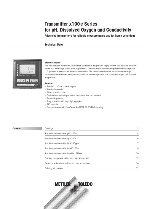
Transmitter x100e Seriesfor pH, Dissolved Oxygen and ConductivityAdvanced transmitters for reliable measurements and for harsh conditions Technical DataDrawings2Specifications transmitter pH 2100e 4Specifications transmitter O 24100e 6Specifications transmitter O 24100ppb 7Specifications transmitter Cond 7100e 8Specifications transmitter Cond Ind 7100e 10Terminal assignment «Advanced Line» transmitters 12General specifications «Advanced Line» transmitters 14Ordering information17Short descriptionThe cost-effective Transmitter X100 Series are suitable designed for highly reliable and accurate measure-ments in a wide range of industrial applications. The instruments are easy to operate and the large-size LCD provides substantial all essential information. The measurement values are displayed in largecharacters and additional pictographs explain the function operation and advise any signal or functional irregularities.Features–Two 0/4…20 mA current outputs –Two limit contacts –Alarm & wash contact–Continuous monitoring of sensor and transmitter performance –Sensor diagnostics–Easy operation with help of pictographs –PID controller–Communication with EasyClean, the METTLER TOLEDO cleaningContentsDrawings AssemblyMounting1Sealing plugs2Hexagon nuts3Pg cable glands4Rubber reducer5Pg plug6Enclosure screws7Hinge pin8Cable ties9Filler plugs10Gaskets11Washer12Jumper876541Cable gland (3 pieces)2Breakthroughs for cablegland or conduit 1/2 ",Ø 21.5 mm(2 breakthroughs).Conduits not included!3Holes for post mounting4Holes for wall mountingDrawingsPipe mounting with ZU 0274 bracket kitProtective hood ZU 0276 for wall and pipe mountingPanel-mount kit ZU 0275165 mm 132 mm173 m m1 Protected hood (if required)2 Hose clamps with worm gear drive to DIN 3017(2 pieces)3 Postmounting plate4 For vertical orhorizontal post/pipe mounting5 Self-tapping screws1 Screws2 Seal3 Control panel4 Span pieces5 Threaded sleevesSpecifications Transmitter pH 2100e pH/mV input Input for pH, ORP electrodes or ISFETMeasurement range –1500…+1500 mVDisplay range pH value –2.00…16.00ORP –1999…+1999 mVGlass electrode input1)Input resistance > 0.5 x 10 12ΩInput current < 2 x 10 –12AReference electrode input1)Input resistance > 1 x 10¹⁰ΩInput current < 1 x 10 –10AMeas. error 1,2,3)pH value< 0.02mV value< 1 mVElectrodestandardization pH *Operating modes-BUF Calibration with automatic buffer recognition Calimatic:Buffer sets-01-Mettler-Toledo 2.00/4.01/7.00/9.21-02-Merck/Riedel de Haen 2.00/4.00/7.00/9.00/12.00-03-Ciba (94) 2.06/4.00/7.00/10.00-04-NIST technical 1.68/4.00/7.00/10.01/12.46-05-NIST standard 1.679/4.006/6.865/9.180-06-HACH 4.00/7.00/10.18-07-WTW technical buffers 2.00/4.01/7.00/10.00-PRD Product Calibration-MAN Calibration with manual entry of individual buffer values-DAT Data entry of premeasured electrodesZero point adjustment ±200 mVMax. calibration range Asymmetry potential: ±60 mVSlope: 80…103 % (47.5…61 mV/pH)Sensor standardizationORP*ORP calibrationMax. calibration range –700…+700D mVCal timer 0000…9999 hSensocheck automatic monitoring of glass andreference electrode (can be disabled)Sensoface provides information on the electrode condition.Evaluation of zero/slope, response,calibration interval, SensocheckSpecifications Transmitter pH 2100e Temperature input *Pt100/Pt1000/NTC 30 kΩ / NTC 8,55 kΩ2-wire connection, adjustableMeasurement range Pt100/Pt1000: –20.0…+ 200.0 °C/–4…+ 392 °FNTC 30 kΩ – 20.0…+ 150.0 °C/–4…+ 302 °FNTC 8.55 kΩ –10.0…+ 130.0 °C/+14…+ 266 °FAdjustment range 10 KResolution0.1 °C/1 °FMeas. error 1,2,3)< 0.5 K (< 1 K for Pt100; <1K for NTC >100 °C)Temp. compensation Linear –19.99…+19.99 %/Kof process medium (reference temp. 25 °C)Power output for operating an ISFET adapter+ 3 V/0.5 mA– 3 V/0.5 mA*User-defined1)To IEC 746 Part 1, at nominal operating conditions2)± 1 count3)Plus sensor errorSpecifications Transmitter O24100e Dissolved oxygen inputSensor type A:InPro6000 (6800)Sensor type B:InPro6900Measuring current-2…1800 nAResolution0.05 nA (with Vpol ≤ 800 mV and Vref ≤ 200 mV)Saturation (–10…80 °C)0…500 %Meas. error1,2,3)0.5 % of meas. val. +0.5 %Concentration (–10…80 °C)0.00…50.00 mg/l0.00…50.00 ppmMeas. error 1,2,3)0.5 % of meas. val. + 0.05 mg/lor 0.05 ppmAdm. guard current20 µAPolarization voltage * 0…1000 mVProcess pressure* 0.000…9.999 bar(…999.9 kPa/…145.0 psi)Salt correction * 00.00…45.00 g/kgSensor standardizationOperating modes * DO saturation (automatic)DO concentration (automatic)Product calibrationZero point calibrationCalibration range Zero point ± 2 nASensor type A Slope 25…130 nA(at 25 °C, 1013 mbars)Calibration range Zero point ± 2 nASensor type B Slope200…550 nA(at 25 °C, 1013 mbars)Calibration timer * 0000…9999 hPressure correction * 0.000…9.999 bars/999.9 kPa/145.0 psiSensocheck Monitoring for short circuits/open circuits (can be disabled)Sensoface Provides information on the sensor conditionEvaluation of zero/slope, response, calibration interval, SensocheckTemperature input *NTC 22 kΩ / NTC 30 kΩ*2-wire connection, adjustableMeasurement range– 20.0…+150.0 °C/– 4…+ 302 °FAdjustment range10 KResolution0.1 °C/1 °FMeas. error 1,2,3)< 0.5 K (< 1 K at >100 °C)*User-defined1)To IEC 746 Part 1, at nominal operating conditions2)± 1 count3)Plus sensor errorSpecifications Transmitter O24100ppb Dissolved oxygen inputSensor type A:InPro6000 (6800)Sensor type B:InPro6900Measuring current-2…600 nAResolution0.01 nA (with Vpol ≤ 500 mV and Vref ≤ 200 mV)Saturation (–10…80 °C)0.0.…120.0 %Meas. error1,2,3)0.5 % of meas. val. +0.1 %Concentration (–10…80 °C)0000…9999 µg/l0000…9999 ppb0.0000…9.999 mg/l0.0000…9.999 ppmMeas. error 1,2,3)0.5 % of meas. val. +0.005 mg/lor 0.005 ppmAdm. guard current20 µAPolarization voltage* 0…1000 mVProcess pressure* 0.000…9.999 bars(to 999.9 kPa/…145.0 psi)Salt correction* 00.00…45.00 g/kgSensor standardizationOperating modes * DO saturation (automatic)DO concentration (automatic)Product calibrationZero point calibrationCalibration range Zero point ± 2 nASensor type A Slope25…130 nA(at 25 °C, 1013 mbars)Calibration range Zero point ± 2 nASensor type B Slope 200…550 nA(at 25 °C, 1013 mbars)Calibration timer * 0000…9999 hPressure correction * 0.000…9.999 bars/999.9 kPa/145.0 psiSensocheck Monitoring for short circuits/open circuits (can be disabled)Sensoface Provides information on the sensor conditionEvaluation of zero/slope, response, calibration interval, SensocheckTemperature input *NTC 22 kΩ/ NTC 30 kΩ*2-wire connection, adjustableMeasurement range–20.0…+150.0 °C/–4…+302 °FAdjustment range10 KResolution0.1 °C/1 °FMeas. error 1,2,3)< 0.5 K (< 1 K at >100 °C)*User-defined1)To IEC 746 Part 1, at nominal operating conditions2)± 1 count3)Plus sensor errorSpecifications Transmitter Cond 7100e Conductivity input Input for 2-e or 4-e conductivity sensorsWorking range4-electrode sensor:0.2 µS *c …1000 mS * c (c = cell constant)2-electrode sensor:0.2 µS *c …200 mS * c(the actual range is very much depending on the sensor used,display limited to 3500 mS)Effective ranges Conductivity0.000…9.999 µS/cm00.00…99.99 µS/cm000.0…999.9 µS/cm0000…9999 µS/cm0.000…9.999 mS/cm00.00…99.99 mS/cm000.0…999.9 mS/cm0.000…9.999 S/m00.00…99.99 S/mResistivity00.00…99.99 MΩcmConcentration0.00…9.99 % by wt.Salinity0.0…45.0 ‰ (0…35 °C)Measurement error1,2,3)< 1% of measured value +0.4 µS * cConc. measurements-01- NaCl0.00…9.99 % by wt.(0 …60°C)-02- HCl0.00…9.99 % by wt.(–20…50 °C)-03- NaOH0.00…9.99 % by wt.(0…100 °C)-04- H2SO40.00…9.99 % by wt.(–17…110 °C)-05- HNO30.00…9.99 % by wt.(–17…50 °C)Sensor standardization Input of cell constant with simultaneous displayof conductivity value and temperatureInput of conductivity value with simultaneous displayof cell constant and temperatureProduct calibrationTemperature probe adjustmentPermissible cell constant00.0050…19.9999 cm–1Sensocheck Monitoring of sensor polarization and cable capacitance (can be disabled)Sensoface Provides information on the sensor condition (Sensocheck)Sensor monitor Display of direct measurement values for validationpurpose (resistance/temperature)USP-Function Monitoring of conductivity of water for pharmaceuticalapplications to USP (USP <645>) with adjustable limitvalues (10…100 % of USP value)Specifications Transmitter Cond 7100e Temperature input*)Pt100/Pt1000/NTC 30 kΩ / NTC 8.55 kΩ2-wire connection, adjustableMeasuring range Pt100/Pt1000–20…+200 °C / –4…+392 °FNTC 30 kΩ–20…+150 °C / -4…+302 °FNTC 8.55 kΩ–10…+130 °C / +14…+266 °FResolution0.1 °C / 1 °FError1,2,3)0.5 K (< 1 K with Pt100; < 1 K with NTC > 100 °C)Temperature compensation(OFF)not compensated(ref. temp. 25 °C)(Lin)linear, 0.00…19.99 %/K, –20…130 °C(NLF)natural waters to EN 27888, 0…36 °C(nACL)ultrapure water with NaCl traces, 0…120 °C(HCL)ultrapure water with HCl traces, 0…120 °C(nH3)ultrapure water with NH3traces, 0…120 °C*User-defined1)To IEC 746 Part 1, at nominal operating conditions2)± 1 count3)Plus sensor errorSpecifications Transmitter Cond Ind 7100e Conductivity input Input for inductive sensorsWorking range Conductivity0.000…1999 mS/cmConcentration0.00…100 % by wt.Salinity0.0…45.0 ‰ (0…35 °C)Effective ranges Conductivity0.000…9.999 mS/cm00.00…99.99 mS/cm000.0…999.9 mS/cm0000…1999 mS/cm0.000…9.999 S/m00.00…99.99 S/mConcentration0.00…99.99 %Salinity0.0…45.0 ‰ (0…35 °C)Measurement error1,2,3)< 1% of measured value +0.005 mSConc. measurements-01- NaCl0…26 %(0…60 °C)-02- HCl0…18 % (–20…50 °C)-03- NaOH0…14 % (0…100 °C)-04- H2SO40…30 % (–17…110 °C)-05- HNO30…30 % (–20…50 °C)-06- H2SO492…99 % (–17…115 °C)-07- HCl22…39 % (–20…50 °C)-08- HNO335…96 % (–20…50 °C)-09- H2SO432…84 % (–17…115 °C)-10- NaOH18…50 % (0…100 °C)Sensor standardization Input of cell factor with simultaneous displayof conductivity value and temperatureInput of conductivity value with simultaneous displayof cell factor and temperatureProduct calibrationZero point calibrationTemperature probe adjustmentPermissible cell factor00.100…19.999Permissible transfer ratio01.00…199.99Permissible zero pointdeviation± 0.5 mS/cmSensocheck Monitoring of sender coil and leads for short circuiting,and of the receiver coil for disruption (can be disabled)Sensoface Indicates sensor status (zero point, sensocheck)Sensor monitor Display of direct measurement values for validationpurpose (resistance /temperature)Specifications Transmitter Cond Ind 7100e Temperature input*Pt100/Pt1000/NTC 100 kΩ2-wire connection, adjustableMeasuring range Pt100/Pt1000–20…+200 °C / –4… +392 °FNTC–20…+130 °C / –4… +266 °FResolution0.1 °C / 1 °FError1,2,3)0.5 K (< 1 K with Pt100; < 1 K with NTC > 100 °C)Temperature compensation(OFF)not compensated(ref. temp. 25 °C)(LIN)linear, 0.00…19.99 %/K(NLF)natural waters to EN 27888 (0…35 °C)* User-defined1) To IEC 746 Part 1, at nominal operating conditions2) ± 1 count3) Plus sensor errorTerminal assignment «Advanced Line» transmittersTransmitter O 24100 ppbTransmitter O 24100 eTransmitter pH 2100 eTerminal assignment«Advanced Line» transmitters Transmitter Cond 7100eTransmitter Cond Ind 7100eGeneral specifications «Advanced Line» transmitters HOLD input Galv. separated (OPTO coupler)Function Switches device to HOLD stateSwitching voltage 0…2 V (AC/DC) hold inactive10…30 V (AC/DC) hold activeCONTROL input pH/O2)Galv. separated (OPTO coupler)Function Control input for automatic cleaning/calibration systemSwitching voltage0…2 V (AC/DC) inactive10…30 V (AC/DC) activeCONTROL input (Cond)Galv. separated (OPTO coupler)Function Switches between two parameter setsSwitching voltage0…2 V (AC/DC) set #1 active10…30 V (AC/DC) set #2 activeOutput 10/4…20 mA, max. 10 V, floating(galv. connected to output 2)Process variable *pH 2100 e pH/mVO24100e%, mg/lO24100 ppb%, mg/lCond 7100e conductivity, resistivity, concentration, salinityCond Ind 7100e conductivity, concentration, salinityCurrent characteristics*linear or logarithmic (depends on transmitter)Overrange *22 mA in the case of error messageOutput filter *Low-pass, filter time constant 0…120 sMeas. error1)< 0.3 % of current value +0.05 mAStart/end of scale As desired within measuring rangeAdm. span pH 2100e 2.00…18.00/200…3000 mV024100e 5…500 %, 0.5…50 mg/l024100 ppb 2…200 %, 0.2…10 mg/lCond 7100e LIN 5 % of selected measuring rangeLOG 1 decadeCond Ind 7100e LIN 5 % of selected measuring rangeLOG 1 decadeOutput 20/4…20 mA, max. 10 V, floating(galv. connected to output 1)Process variable TemperatureOverrange *22 mA in the case of temp error messagesOutput filter *Low-pass, filter time constant 0…120 sMeas. error 1)< 0.3 % of current value + 0.05 mAStart/end of scale *pH, Cond: –20…+200 °C/–4…+392 °F, 02:–20…+150 °C/–4...+302 °FAdm. span pH, Cond: 20…320 K, 02:20…170 KAlarm contact Relay contact, floatingContact ratings AC < 250 V/< 3 A/< 750 VADC < 30 V/< 3 A/< 90 WContact response N/C (fail-safe type)Alarm delay 0000…0600 sGeneral specifications «Advanced Line» transmitters Limit values Output via relay contacts R1, R2Contacts R1, R2 floating, but inter-connectedContact ratings AC < 250 V/< 3 A/< 750 VADC < 30 V/< 3 A/< 90 WContact response *N/C or N/ODelay *0000…9999 sSwitching points *As desired within measuring rangeHysteresis *pH 2100e0…5.00 pH/0…500 mV024100e 0…50 %/0…5.00 mg/l (ppm)024100ppb 0…50 %/0…5.00 mg/l (ppm)Cond 7100e0…50 % of measuring rangeCond Ind 7100e0…50 % of measuring rangePID process controller Output via relay contacts R1, R2 (see limit values)Setpoint specification *pH 2100e–02.00…16.00/– 1500…+1500 mV024100e 0…500 % / 0…50 mg/l024100ppb 0…120% / 0…9.999 mg/lCond 7100e within selected measuring rangeCond Ind 7100e within selected measuring rangeNeutral zone *pH 2100e0…5.00 pH / 0…+500 mV024100e 0…50 % / 0…5 mg/l024100ppb 0…50 % / 0…5 mg/l (ppm)Cond 7100e within selected measuring rangeCond Ind 7100e max. 50 % of selected measuring rangeP-action *Controller gain K R:0010…9999 %I-action component *Reset time Tr: 0000…9999 s(0000 s = no integral action)D-action component *Derivative-actiontime Td: 0000…9999 s(0000 s = no derivative action)Controller type*Pulse length controller or pulse frequency controllerPulse period *0001…0600 s, min. ON time 0.5 s (pulse length controller)Max. pulse frequency *0001…0180 min–1(pulse frequency controller)Cleaning function/Relay contact, floating2nd parameter set for controlling a simple rinsing system or an automatic cleaning systemor to show that 2nd parameter set is activeContact ratings AC < 250 V/< 3 A/< 750 VADC < 30 V/< 3 A/< 90 WContact response *N/C or N/O (cleaning function)N/O (2nd parameter set)Rinsing interval *000.0…999.9 h(000.0 h = cleaning function switched off)Cleaning time *0000…1999 sCalibration interval *000.0…999.9 hCleaning interval*000.0…999.9 h*User-defined1)To IEC 746 Part 1, at nominal operating conditions2)± 1 count3)Plus sensor errorGeneral specifications«Advanced Line» transmitters Display LC display, 7-segment with iconsMain display Character height 17 mm, unit symbols 10 mmSecondary display Character height 10 mm, unit symbols 7 mmSensoface 3 status indicators (friendly, neutral, sad smiley)Mode indicators 5 status bars: «meas», «cal», «alarm», «cleaning», «config»18 further icons for configuration and messagesAlarm indication Red LED in case of alarm or HOLD, user definedKeypad 5 keys: [cal] [conf] [] [] [enter]Service functionsCurrent source Current specifiable for output 1 and 2 (00.00…22.00mA)Manual controller Controller output entered directly (start of control process)Device self-test Automatic memory test (RAM, FLASH, EEPROM)Display test Display of all segmentsLast Error Display of last error occurredSensor monitor Display of direct, uncorrected sensor signal (electrode/sensor)Relay test Manual control of the four switching contactsParameter sets*Two selectable parameter sets for different applicationsData retention Parameters and calibration data > 10 years (EEPROM)EMC EN 61326EN 61326/A1Lightning protection EN 61000-4-5, Installation Class 2Protection against Protective separation of all extra-low-voltageelectrical shock circuits against mains as per EN 61010FM/CSA NI, Class 1, Div 2, Group A, B, C, D, T4Power supply24 (–15%)…230 (+10%) V AC/DC; approx. 5 VA, 2.5 WAC: 45…65 HzOvervoltage category II, Class IINominal operating conditionsAmbient temperature– 20…+55 °C / –4...+131 °FTransport/Storage temp – 20…+70 °C / -4...+158 °FRelative humidity 10…95 % non condensingPower supply24 (–15%)…230 (+ 10 %) V AC/DCFrequency for AC 45…65 HzGeneral specifications and ordering information«Advanced Line» transmittersEnclosure molded enclosure made of PBT (polybutylene terephtalate)Color Bluish gray RAL 7031Assembly• Wall mounting• Pipe mounting: Ø 40…60 mm,Ø 30…45 mm• Panel mounting, cutout to DIN 43 700, sealed against panelDimensions H x W x L: 144 x 144 x 105 mm (5.67 x 5.67 x 4.13")Ingress protection IP 65/NEMA 4XCable glands 3 breakthroughs for cable glands M20 x 1.52 breakthroughs for NPT 1/2 " or Rigid Metallic ConduitWeight approx. 1 kg*User-defined1)To IEC 746 Part 1, at nominal operating conditions2)± 1 count3)Plus sensor errorOrdering information Array Transmitter pH 2100e pH 2100e52 121 102Transmitter O24100e O24100e52 121 103Transmitter O2 4100ppb O24100ppb52 121 104Transmitter Cond 7100e Cond 7100e52 121 126Transmitter Cond Ind 7100e Cond Ind 7100e52 121 127Installation accessoriesBracket kit ZU 027452 120 741Panel-mount kit ZU 027552 120 740Protective hood ZU 027652 120 739NotesNotesMETTLER TOLEDO Market Organizations Subject to technical changes.© Mettler-Toledo AG, Process Analytics 08/13 Printed in Switzerland. 52 121 132Mettler-Toledo AG, Process Analytics Im Hackacker 15, CH–8902 Urdorf Tel. + 41 44 729 62 11, Fax +41 44 729 66 Sales and Service:Australia Mettler-Toledo Ltd.220 Turner Street Port Melbourne AUS-3207 Melbourne/VIC Phone +61 1300 659 761Fax +61 3 9645 3935e-mail *****************Austria Mettler-Toledo Ges.m.b.H.Südrandstraße 17A-1230 Wien Phone +43 1 604 19 80Fax +43 1 604 28 80e-mail ***********************Brazil Mettler-Toledo Ind. e Com. Ltda.Avenida Tamboré, 418TamboréBR-06460-000 Barueri/SP Tel.+55 11 4166 7400Fax +55 11 4166 7401e-mail *******************.br *******************.br China Mettler-Toledo Instruments (Shanghai) Co. Ltd.589 Gui Ping Road Cao He Jing CN-200233 Shanghai Phone +86 21 64 85 04 35Fax +86 21 64 85 33 51e-mail *************** Croatia Mettler-Toledo d.o.o.Mandlova 3HR-10000 Zagreb Phone +385 1 292 06 33Fax +385 1 295 81 40e-mail ****************Czech Republic Mettler-Toledo s.r.o.Trebohosticka 2283/2CZ-100 00 Praha 10 Phone +420 2 72 123 150Fax +420 2 72 123 170e-mail *****************Denmark Mettler-Toledo A/S Naverland 8DK-2600 Glostrup Phone +45 43 27 08 00Fax +45 43 27 08 28e-mail ****************France Mettler-Toledo Analyse Industrielle S.A.S.30, Boulevard de Douaumont F-75017 Paris Phone +33 1 47 37 06 00Fax +33 1 47 37 46 26e-mail **************Germany Mettler-Toledo GmbH Prozeßanalytik Ockerweg 3D-35396 Gießen Phone +49 641 507 333Fax +49 641 507 397e-mail **************Great Britain Mettler-Toledo LTD 64 Boston Road, Beaumont Leys GB-Leicester LE4 1AW Phone +44 116 235 7070Fax +44 116 236 5500e-mail *******************Hungary Mettler-Toledo Kereskedelmi KFT Teve u. 41HU-1139 Budapest Phone +36 1 288 40 40Fax +36 1 288 40 50e-mail ***************India Mettler-Toledo India Private Limited Amar Hill, Saki Vihar Road Powai IN-400 072 Mumbai Phone +91 22 2857 0808Fax +91 22 2857 5071e-mail *****************Italy Mettler-Toledo S.p.A.Via Vialba 42I-20026 Novate Milanese Phone +39 02 333 321Fax +39 02 356 2973e-mail **************************Japan Mettler-Toledo K.K.Process Division 6F Ikenohata Nisshoku Bldg.2-9-7, Ikenohata Taito-ku JP-110-0008 Tokyo Phone +81 3 5815 5606Fax +81 3 5815 5626e-mail **********************Malaysia Mettler-Toledo (M) Sdn Bhd Bangunan Electroscon Holding, U 1-01Lot 8 Jalan Astaka U8/84Seksyen U8, Bukit Jelutong MY-40150 Shah Alam Selangor Phone +60 3 78 44 58 88 Fax +60 3 78 45 87 73e-mail ****************************Mexico Mettler-Toledo S.A. de C.V.Ejercito Nacional #340Col. Chapultepec Morales Del. Miguel Hidalgo MX-11570 México D.F.Phone +52 55 1946 0900e-mail *****************Poland Mettler-Toledo (Poland) Sp.z.o.o.ul. Poleczki 21PL-02-822 Warszawa Phone +48 22 545 06 80Fax +48 22 545 06 88e-mail *************Russia Mettler-Toledo Vostok ZAO Sretenskij Bulvar 6/1Office 6RU-101000 Moscow Phone +7 495 621 56 66Fax +7 495 621 63 53e-mail **************Singapore Mettler-Toledo (S) Pte. Ltd.Block 28Ayer Rajah Crescent #05-01SG-139959 Singapore Phone +65 6890 00 11Fax +65 6890 00 12+65 6890 00 13e-mail ****************Slovakia Mettler-Toledo s.r.o.Hattalova 12/A SK-83103 Bratislava Phone +421 2 4444 12 20-2Fax +421 2 4444 12 23e-mail *************Slovenia Mettler-Toledo d.o.o.Pot heroja Trtnika 26SI-1261 Ljubljana-Dobrunje Phone +386 1 530 80 50Fax +386 1 562 17 89e-mail *******************South Korea Mettler-Toledo (Korea) Ltd.Yeil Building 1 & 2 F 124-5, YangJe-Dong SeCho-Ku KR-137-130 Seoul Phone +82 2 3498 3500Fax +82 2 3498 3555e-mail *****************Spain Mettler-Toledo S.A.E.C/Miguel Hernández, 69-71ES-08908 L’Hospitalet de Llobregat (Barcelona)Phone +34 902 32 00 23Fax +34 902 32 00 24e-mail *************Sweden Mettler-Toledo AB Virkesvägen 10Box 92161SE-12008 Stockholm Phone +46 8 702 50 00Fax +46 8 642 45 62e-mail ****************Switzerland Mettler-Toledo (Schweiz) GmbH Im Langacher Postfach CH-8606 Greifensee Phone +41 44 944 45 45Fax +41 44 944 45 10e-mail ******************Thailand Mettler-Toledo (Thailand) Ltd.272 Soi Soonvijai 4Rama 9 Rd., Bangkapi Huay Kwang TH-10320 Bangkok Phone +66 2 723 03 00Fax +66 2 719 64 79e-mail ****************************USA/Canada Mettler-Toledo Ingold, Inc.36 Middlesex Turnpike Bedford, MA 01730, USA Phone +1 781 301 8800Freephone +1 800 352 8763Fax +1 781 271 0681e-mail**************。
SPEC-SX-020HS1001N0-07A0-S0

产品规格书SX-020HS1001N0-07A0-S0公司名称项目型号客户签回产品: 2.0TFT240*320版本:V01日期:批准审核制表目录:项目内容页码1版本历史1 2结构说明2 3机构图3 4接口定义4 5各参数极限值5 6电气特性6 7光学特性7 8可靠性测试8 9包装9 10出货检验标准10--141.版本历史样品版本文件版本日期描述修改人V01首次开发Z2.机构说明项目内容单位外型尺寸35.7*51.2*2.4mm显示尺寸 2.0inch 显示形式240*(RGB)*320Pixels-显示区(A.A)30.6(W)*40.8(H)mm 视角ALL-驱动IC ST7789V-背光类型3LEDS-3.机构图4.接口定义:NO.SYMBOL Description 1LEDK Backlight-.2LEDA Backlight+.3VDD Supply voltage(3.3V).4TE Tearing effect output pin to synchronize MPU to frame writing, activated by S/W command.When this pin is not activated,this pin is low.If not used,open this pin.5CSChip select input pin(“Low”enable). fix this pin at VCI or GND when not in use.6RESETThis signal will reset the device and it must be applied to properlyinitialize the chip.Signal is active low.7D/C -Write enable in MCU parallel interface.-Display data/command selection pin in4-line serial interface. -Second Data lane in2data lane serial interface.-If not used,please fix this pin at VDDI or DGND.8SCLK -Display data/command selection pin in parallel interface.-This pin is used to be serial interface clock.DC=’1’:display data or parameter.DC=’0’:command data.-If not used,please fix this pin at VDDI or DGND.9SDA Serial input signal. 10GND Ground5.各参数极限值:项目符号最小值典型值最大值单位操作温度T OP-20-70℃存储温度T ST-30-80℃6.电气特性背光:项目符号额定值单位60mA 工作电流IBL3.2V V工作电压VBL亮度--CD/M2(*)*此亮度值为组装LCD时的的值。
FX-100 商品说明资料 中文(简体字) 20061226解读

光量
※FX-100的4元素发光素子能对应长期光量变动, 所以不需搭载APC电路。
強制补正
时间 素子使用寿命
8
社外秘
建议使用市场出售的连接器、不使用中继连接器
光纤放大器 连接器型
传感器制造商专用 的帶连接器电缆
加工成用户规格的连接器
转入PLC、PC等控制系
光纤放大器 电缆外伸型
如用户可將连接器加工成日本压接端子制造的连接器(见下图)的话...
社外秘
数字显示光纤传感器 FX-100 series 商品说明资料
针对PEWA的说明资料。 严禁对外(包括代理店)流出。
2006年11月 SUNX株式会社 海外营业部
1
社外秘
1.目标市场
2
Line Up
商品体系 FX-300 FX-301 FX-305 数字显示 SUNX标准型 高功能型
社外秘
FX-400
PRO模式
高标准设定
可进行外部设定,以及自动跟 踪基准值等高标准设定
与压力传感器DP-100的操作結构相同。 与压力传感器DP-100配套使用、可统一操作性,易于理解。 与DP-100相同,具有2画面显示, 通过『直接调节』易於变更基准值。
12
社外秘
RUN模式
[变更基准值] 提高基准值時 :按ON按钮。
MODE
设定定时
[可设定以下时间] 1ms、5ms、10ms、20ms、40ms、 50ms、100ms、500ms、1s、
M3贯穿孔 ※不使用金属支架也可 直接安装
4芯电缆 按照 茶色:+ 蓝色:- 黑色:out 白色:in 搭载外部输入线。 ・可进行外部设定。
★采用4元素发光素子 不易老化!!
2022新TC-100HS 说明书

TC-100HS 用户手册天创恒达数字视频技术开发(北京)有限公司目录一、TC-100HS 产品概述 (2)二、编码器技术参数 (3)2.1 TC-100HS 介绍 (3)2.2 TC-100HS 接口说明 (7)三、编码器后台参数 (8)3.1 主界面说明 (8)3.2 微信端操作说明 (15)3.3 微信小程序端操作说明 (22)3.4 网页端操作说明 (29)四、编码器规格参数 (30)一、TC-100HS 产品概述TC-100HS专业聚合高清直播编码器,将摄像机、照相机等多种视频源的高清音视频进行编码处理。
通过多链路聚合方式传输到聚合服务器,服务器接收并输出IP视频流信号在终端显示,系统利用聚合网络高带宽、低时延的优点,实现了移动状态下实时传输高清视频的效果。
配合云端的聚合分发服务器,用户可在电脑或手机上实时收看现场直播的实时画面,直播编码器可广泛应用于商务活动(视频会议、产品发布、开幕式、奠基仪式)、教育培训、医疗手术、无人机航拍、婚庆现场、风景旅游、体育赛事、活动现场(公益活动、娱乐活动、音乐会、集体活动 )等。
产品图如下:(系统框架图)二、编码器技术参数2.1 TC-100HS 介绍TC-100HS 是基于多链路聚合技术和H.264编码技术的高清音视频编码器,它配备两个USB 4G棒和一个内置4G模块,同时支持WIFI和有线网络接入,高可靠性的链路聚合技术能最大限度地汇聚所有网络链路带宽来实时传输高清视频。
独特的微信小程序配置,可跨平台支持IOS和安卓,不再需要下载安装APP扫码即可配置设备,查看直播状态。
此外设备支持远程网络云配置,支持本地WEB配置,灵活方便;专业的LCD触摸屏,可直接预览直播图像进入设备后的视频效果,直观浏览设备的配置、网络连接、直播状态等等,还可通过菜单直接对设备进行配置和画面组合切换。
下图为TC-100HS 的接口示意图:注:①有线网口:连接有线网络②WIFI天线:连接WIFI 天线接收WIFI 信号③USB接口:连接USB 4G 棒④USB接口:连接USB 4G棒⑤音频监听口:可监听音频注:⑥AUDIO IN 音频输入:可接入3.5 Line in音频和麦克风音频⑦SDI输入:接入SDI视频信号⑧SDI 环出:可实时环出SDI视频信号⑨HDMI 输入:接入HDMI 视频信号⑩电源开关:开机按键⑪SIM 卡槽:可插入4G SIM卡(Nano卡)⑫充电接口:接入15V-1.6A 电源供设备充电⑬4G天线:接收4G信号注:⑭二维码按键:按下可以快速调出二维码⑮推流按键:可控制推流开始推流和结束推流注:⑯防滑脚垫:设备可防滑⑰风扇:设备散热(请勿讲设备平躺或堵住,影响散热)注:⑱热靴:可固定到摄像机上2.2 TC-100HS 接口说明SIM卡安装TC-100HS有1个内置Nano SIM卡槽和两个外置USB 4G棒①内置SIM卡安装:可插入不同运营商的Nano SIM卡,从而保证传输可靠性。
FortiGate 100F系列产品说明书

FortiGate ® 100F SeriesFG-100F and FG-101FThe FortiGate 100F series provides an application-centric, scalable, and secure SD-WAN solution with Next Generation Firewall (NGFW) capabilities for mid-sized to large enterprises deployed at the campus or branch level. Protects against cyber threats with system-on-a-chip acceleration and industry-leading secure SD-WAN in a simple, affordable, and easy to deploy solution. Fortinet’s Security-Driven Networking approach provides tight integration of the network to the new generation of security.NGFW Threat ProtectionInterfaces20 Gbps 2.6 Gbps 1.6 Gbps 1 GbpsMultiple GE RJ45, GE SFP and 10 GE SFP+ slotsRefer to specification table for detailsSecurity n Identifies thousands of applications inside network traffic for deep inspection and granular policy enforcementn Protects against malware, exploits, and maliciouswebsites in both encrypted and non-encrypted traffic n Prevent and detect against known and unknown attacksusing continuous threat intelligence from AI-powered FortiGuard Labs security servicesPerformancen Delivers industry’s best threat protection performance and ultra-low latency using purpose-built security processor (SPU) technologyn Provides industry-leading performance and protection forSSL encrypted trafficCertificationn Independently tested and validated best security effectiveness and performancen Received unparalleled third-party certifications from NSSLabsNetworkingn Delivers advanced networking capabilities that seamlessly integrate with advanced layer 7 security and virtual domains (VDOMs) to offer extensive deployment flexibility, multi-tenancy and effective utilization of resourcesn Delivers high-density, flexible combination of varioushigh-speed interfaces to enable best TCO for customersfor data center and WAN deploymentsManagement n Includes a management console that is effective, simple to use, and provides comprehensive network automation and visibility.n Provides Zero Touch Integration with Security Fabric’sSingle Pane of Glass Managementn Predefined compliance checklist analyzes the deploymentand highlights best practices to improve overall securitypostureSecurity Fabric n Enables Fortinet and Fabric-ready partners’ products to provide broader visibility, integrated end-to-end detection, threat intelligence sharing, and automated remediationNext Generation Firewall Secure SD-WANSecure Web GatewayDATA SHEETDATA SHEET | FortiGate® 100F SeriesDEPLOYMENTN ext Generation Firewall (NGFW)§Reduce the complexity and maximize your ROI by integrating threatprotection security capabilities into a single high-performance network security appliance, powered by Fortinet’s Security Processing Unit (SPU) §Full visibility into users, devices, and applications across the entire attack surface, and consistent security policy enforcement irrespective of asset location §Protect against network exploitable vulnerabilities with industry-validated IPS that offers low latency and optimized network performance §Automatically block threats ondecrypted traffic using the industry’s highest SSL inspection performance, including the latest TLS 1.3standard with mandated ciphers §Secure Web Gateway (SWG)§Secure web access from both internal and external risks, even for encrypted traffic at high performance §Enhanced user experience with dynamic web and video caching §Block and control web access based on user or user groups across URLs and domains §Prevent data loss and discover user activity to known and unknown cloud applications §Block DNS requests against malicious domains §Multi-layered advanced protection against zero-day malware threats delivered over the webSecure SD-WAN§Consistent business application performance with accurate detection, dynamic WAN path steering on any best-performing WAN transport §Accelerated multi-cloud access for faster SaaS adoption with cloud-on-ramp §Self-healing networks with WAN edge high availability, sub-second traffic switchover-based and real-time bandwidth compute-based traffic steering §Automated overlay tunnels provide encryption and abstracts physical hybrid WAN making it simple to manage §Simplified and intuitive workflow with SD-WAN orchestrator for management and zero touch deployment ENTERPRISE Secure Access SwitchEnterprise Branch Deployment (Secure SD-WAN)DATA SHEET | FortiGate® 100F Series FORTINET SECURITY FABRICFortiOS™Operating SystemFortiOS, Fortinet’s leading operating system enable the convergence of high performing networking and security across the Fortinet Security Fabric delivering consistent and context-aware security posture across network endpoint, and clouds. The organically built best of breed capabilities and unified approach allows organizations to run their businesses without compromising performance or protection, supports seamless scalability, and simplifies innovation consumption.The release of FortiOS 7 dramatically expands the Fortinet Security Fabric’s ability to deliver consistent security across hybrid deployment models of Hardware, Software, and Software As-a-Service with SASE and ZTNA, among others.Security FabricThe industry’s highest-performing cybersecurity platform,powered by FortiOS, with a rich ecosystem designed to span the extended digital attack surface, delivering fully automated, self-healing network security.§Broad: Coordinated detection and enforcement across the entire digital attack surface and lifecycle with converged networking and security across edges, clouds, endpoints, and users§Integrated: Integrated and unified security, operation, and performance across different technologies, location, deployment options, and the richest ecosystem§Automated: Context aware, self-healing network and security posture leveraging cloud-scale and advanced AI to automatically deliver near-real-time, user-to-application coordinated protection across the FabricThe Fabric empowers organizations of any size to secure and simplify their hybrid infrastructure on the journey to digital innovation.SERVICESFortiGuard™Security ServicesFortiGuard Labs offer real-time intelligence on the threat landscape, delivering comprehensive security updates across the full range of Fortinet’s solutions. Comprised of security threat researchers, engineers, and forensic specialists, the team collaborates with the world’s leading threat monitoring organizations and other network and security vendors, as well as law enforcement agencies.FortiCare™ServicesFortinet is dedicated to helping our customers succeed, and every year FortiCare services help thousands of organizations get the most from their Fortinet Security Fabric solution. We have more than 1,000 experts to help accelerate technology implementation, provide reliable assistance through advanced support, and offer proactive care to maximize security and performance of Fortinet deployments.DATA SHEET | FortiGate® 100F Series SPECIFICATIONSFORTIGATE 100F FORTIGATE 101F Interfaces and ModulesHardware Accelerated GE RJ45 Ports12Hardware Accelerated GE RJ45Management/ HA/ DMZ Ports1 /2 / 1Hardware Accelerated GE SFP Slots4Hardware Accelerated 10 GE SFP+FortiLink Slots (default)2GE RJ45 WAN Ports2GE RJ45or SFP Shared Ports *4USB Port1Console Port1Onboard Storage01x 480 GB SSD Included Transceivers0System Performance — Enterprise Traffic MixIPS Throughput 2 2.6 GbpsNGFW Throughput 2, 4 1.6 GbpsThreat Protection Throughput 2, 5 1 GbpsSystem Performance and CapacityIPv4 Firewall Throughput(1518 / 512 / 64 byte, UDP)20 / 18 / 10 GbpsFirewall Latency (64 byte, UDP) 4.97 μsFirewall Throughput (Packet per Second)15 MppsConcurrent Sessions (TCP) 1.5 MillionNew Sessions/Second (TCP)56,000Firewall Policies10,000IPsec VPN Throughput (512 byte) 111.5 GbpsGateway-to-Gateway IPsec VPN Tunnels 2,000Client-to-Gateway IPsec VPN Tunnels16,000SSL-VPN Throughput 1 GbpsConcurrent SSL-VPN Users(Recommended Maximum, Tunnel Mode)500SSL Inspection Throughput(IPS, avg. HTTPS) 31 GbpsSSL Inspection CPS (IPS, avg. HTTPS) 31,800SSL Inspection Concurrent Session(IPS, avg. HTTPS) 3135,000Application Control Throughput(HTTP 64K) 22.2 GbpsCAPWAP Throughput (HTTP 64K)15 GbpsVirtual Domains (Default / Maximum)10 / 10Maximum Number of FortiSwitchesSupported32Maximum Number of FortiAPs(Total / Tunnel)128 / 64Maximum Number of FortiTokens5,000High Availability Configurations Active / Active, Active / Passive, ClusteringFORTIGATE 100F FORTIGATE 101F Dimensions and PowerHeight x Width x Length (inches) 1.73 x 17 x 10Height x Width x Length (mm)44 x 432 x 254Weight7.25 lbs (3.29 kg)7.56 lbs (3.43 kg) Form Factor(supports EIA/non-EIA standards)Rack Mount, 1 RUAC Power Supply100–240V AC, 50/60 Hz Power Consumption(Average / Maximum)35.1 W / 38.7 W35.3 W / 39.1 W Current (Maximum)100V / 1A, 240V / 0.5AHeat Dissipation119.77 BTU/h121.13 BTU/h Redundant Power Supplies YesOperating Environment and CertificationsOperating Temperature32–104°F (0–40°C) Storage Temperature-31–158°F (-35–70°C) Humidity10–90% non-condensing Noise Level40.4 dBAForced Airflow Side to Back Operating Altitude Up to 7,400 ft (2,250 m) Compliance FCC Part 15B, Class A, CE, RCM, VCCI,UL/cUL, CB, BSMI Certifications ICSA Labs: Firewall, IPsec, IPS, Antivirus,SSL-VPN; IPv6Note: All performance values are “up to” and vary depending on system configuration.1. IPsec VPN performance test uses AES256-SHA256.2. IPS (Enterprise Mix), Application Control, NGFW and Threat Protection are measured withLogging enabled.3. SSL Inspection performance values use an average of HTTPS sessions of different ciphersuites.4. NGFW performance is measured with Firewall, IPS and Application Control enabled.5. Threat Protection performance is measured with Firewall, IPS, Application Control andMalware Protection enabled.DATA SHEET | FortiGate® 100F SeriesCopyright © 2021 Fortinet, Inc. All rights reserved. Fortinet , FortiGate , FortiCare and FortiGuard , and certain other marks are registered trademarks of Fortinet, Inc., and other Fortinet names herein may also be registered and/or common law trademarks of Fortinet. All other productor company names may be trademarks of their respective owners. Performance and other metrics contained herein were attained in internal lab tests under ideal conditions, and actual performance and other results may vary. Network variables, different network environments and other conditions may affect performance results. Nothing herein represents any binding commitment by Fortinet, and Fortinet disclaims all warranties, whether express or implied, except to the extent Fortinet enters a binding written contract, signed by Fortinet’s General Counsel, with a purchaser that expressly warrants that the identified product will perform according to certain expressly-identified performance metrics and, in such event, only the specific performance metrics expressly identified in such binding written contract shall be binding on Fortinet. For absolute clarity, any such warranty will be limited to performance in the same ideal conditions as in Fortinet’s internal lab tests. Fortinet disclaims in full any covenants, representations, and guarantees pursuant hereto, whether express or implied. Fortinet reserves the right to change, modify, transfer, or otherwise revise this publication without notice, and the most current version of the publication shall be applicable.1 GE SFP SX Transceiver Module FN-TRAN-SX 1 GE SFP SX transceiver module for all systems with SFP and SFP/SFP+ slots.1 GE SFP LX Transceiver Module FN-TRAN-LX 1 GE SFP LX transceiver module for all systems with SFP and SFP/SFP+ slots.10 GE SFP+ RJ45 Transceiver Module FN-TRAN-SFP+GC 10 GE SFP+ RJ45 transceiver module for systems with SFP+ slots.10 GE SFP+ Transceiver Module, Short Range FN-TRAN-SFP+SR 10 GE SFP+ transceiver module, short range for all systems with SFP+ and SFP/SFP+ slots.10 GE SFP+ Transceiver Module, Long Range FN-TRAN-SFP+LR 10 GE SFP+ transceiver module, long range for all systems with SFP+ and SFP/SFP+ slots.10 GE SFP+ Transceivers, Extended RangeFN-TRAN-SFP+ER10 GE SFP+ transceiver module, extended range for all systems with SFP+ and SFP/SFP+ slots.ORDERING INFORMATIONBUNDLESFortiGuard BundleFortiGuard Labs delivers a number of security intelligence services to augment the FortiGate firewall platform. You can easily optimize the protection capabilities of your FortiGate with one of these FortiGuard Bundles.Bundles 360 Protection Enterprise Protection Unified Threat ProtectionAdvanced ThreatProtectionFortiCareASE 124x724x724x7FortiGuard App Control Service ••••FortiGuard IPS Service••••FortiGuard Advanced Malware Protection (AMP) — Antivirus, Mobile Malware, Botnet, CDR, Virus Outbreak Protection and FortiSandbox Cloud Service••••FortiGuard Web and Video 2 Filtering Service •••FortiGuard Antispam Service •••FortiGuard Security Rating Service ••FortiGuard IoT Detection Service ••FortiGuard Industrial Service ••FortiConverter Service••SD-WAN Orchestrator Entitlement •SD-WAN Cloud Assisted Monitoring •SD-WAN Overlay Controller VPN Service • Fortinet SOCaaS •FortiAnalyzer Cloud •FortiManager Cloud•1. 24x7 plus Advanced Services Ticket Handling2. Available when running FortiOS 7.0。
霍尼韦尔 S10010 S20010 A使用说明书

® U.S. Registered TrademarkEN0B-0463GE51 R0418Copyright © 2018 Honeywell Inc. • All rights reservedS10010 / S20010SPRING RETURN DIRECT-COUPLED DAMPER ACTUATORS10/20 Nm (88/177 lb-in) FOR MODULATING AND FLOATING CONTROLPRODUCT DATAGENERALThese direct-coupled damper actuators provide modulating / floating control for: ∙ air dampers, ∙ VAV units, ∙ air handlers, ∙ ventilation flaps, ∙ louvers, and∙ reliable control for air damper applications with up to1.5 m 2 / 16 sq.ft (10 Nm / 88 lb-in) or 4.6 m 2 / 50 sq.ft. (20 Nm / 177 lb-in) (seal-less dampers; air friction-dependent).FEATURES∙ Self-centering shaft adapter ∙ Removable access cover∙ Mechanical end limits (non-adjustable)∙Rotation direction selectable by choice of mounting orientation∙ Mountable in any orientation (IP54 only whenmounted on a horizontal shaft with access cover below the shaft)∙ Mechanical position indicatorSPECIFICATIONSSupply voltage S10010 / S20010 24 VAC ±20% / 24 VDC, 50/60 Hz Nominal voltage S10010 / S20010 24 VAC / 24 VDC, 50/60 Hz All values stated hereinafter apply to operation under nominal voltage conditions. Power consumption Holding Driving S10010 5 VA / 5 W 14 VA S20010 5 VA / 5 W 16 VA Ambient limitsAmbient operating limits -40...+60 ︒C Ambient storage limits -40...+70 ︒C Relative humidity 5...95%, non-condensing SafetyProtection standard IP54 Overvoltage category III Lifetime Full strokes 60000 Repositions 1.5 million Full stroke spring return 60000 MountingRound damper shaft 10...27 mm Square damper shaft 13...19 mm Shaft length 25 mm End switch (when included) Rating 5 A (resistive) / 3 A (induct.) Triggering points 7︒ / 85︒ Torque rating S10010 10 Nm (88 lb-in) S20010 20 Nm (177 lb-in) Runtime 90 sec (50 Hz) Spring return timing 20 sec (50 Hz) Rotation stroke 95︒ ± 3︒ Dimensions see Fig. 8 on page 6 Weight 3.2 kg Noise rating Driving 40 dB(A) Holding 20 dB(A) (no audible noise) Spring return 50 dB(A)SmartAct S10010, S20010 – PRODUCT DATAEN0B-0463GE51 R0418 2MODELSorder numbersupply voltage end switchespower consumption torque S1001024 VAC / 24 VDC-- 14 VA (driving) / 5 VA (holding) 10 Nm (88 lb-in) S10010-SW2 2 S20010-- 16 VA (driving) / 5 VA (holding)20 Nm (177 lb-in)S20010-SW2 2Product Identification SystemFig. 1. Product Identification SystemOPERATION / FUNCTIONSContents of Package1 Self-centering shaft adapter2 Retainer clip3 Rotational angle scales (0...90° / 90...0°)4 Mechanical end limits (non-adjustable)5 Hex wrench for manual adjustment6 Rotation direction switch7 Access coverRotary MovementThe actuators are designed to open a damper by driving the damper shaft in either a clockwise or counterclockwise direction.NOTE: Actuators are shipped in the fully-closed (springreturn) position.Position IndicationAn arrow molded into the hub points to tick marks on the label to indicate the hub rotary position.CCW to close (failsafe position)CW to open90°0°45°CW to close (failsafe position)CCW to open90°0°45°Fig. 2. Mounting orientationSmartAct S10010, S20010 – PRODUCT DATA3 EN0B-0463GE51 R0418Manual Adjustment IMPORTANTTo prevent equipment damage, before manual adjustment, you must remove power.The actuator can be operated with no power present. Use this feature during installation or to move and lock the damper or valve shaft position when there is no power.Operating the Manual PositioningTo operate the manual positioning with no power, proceed as follows:1. If the power is ON, turn it OFF.2. Insert the supplied hex wrench (key) as shown in Fig.3. 3. Rotate the key in the direction indicated on the cover.4. Once the desired position has been reached, hold the keyto prevent the spring return from moving the actuator. 5. With the key held in place, use a screwdriver to turn thegear train lock pin in the indicated direction until the detent is reached.NOTE: At the detent, the pin resists further rotation.6. Remove the key without rotating it further.Releasing the Manual PositioningTo release the manual positioning with no power present, proceed as follows:1. Insert the supplied key.2. Turn the key ¼ of a turn in the direction indicated on thecover.3. Remove the key without engaging the gear train lock pin.4. The spring will return the actuator to the failsafe position.NOTE: Once power is restored, the actuator will return tonormal automated control.Fig. 3. Manual positioningInternal End SwitchesNOTE: Only those actuators for which "-SW2" has beenspecified when ordering (e.g.: "S10010-SW2") feature internal end switches.The internal end switches are set to switch from "common" to "normally open" at angles of 7° (±3°) and 85° (±3°), respectively, from the totally counterclockwise position.Fig. 4. Internal end switch triggering pointsMechanical Stroke Limit ReductionFor applications requiring a span of less than 95°, a simple adjustment can be made. When the rotational mounting of the shaft coupling is changed, the actuator drives less than the full 95° stroke.The stroke is adjustable in 5° increments. Once adjusted, the actuator drives until the shaft coupling reaches themechanical stop (part of the housing). The stop causes the motor to discontinue driving, and the shaft coupling drives no farther. When the actuator returns, it stops at the fail-safe position.To set the fail-safe position, proceed as follows:1. Remove the retainer clip from the shaft coupling and set itaside for later use.2. Remove the shaft coupling from the actuator.3. Rotate the coupling to the desired fail-safe position,aligning it based on the stroke labeling. See Fig. 5.EXAMPLE: Setting the shaft coupling to an approx. fail-safeposition of 35° (as indicated on the housing) limits the stroke to 60° (see Fig. 5).4. Install the shaft coupling at this position.5. Replace the retainer clip on the shaft coupling using thegroove of the coupling.6. If necessary, replace the holder and position indicator onthe shaft coupling.SmartAct S10010, S20010 – PRODUCT DATAEN0B-0463GE51 R0418 4Fig. 5. Stroke reductionINSTALLATIONThese actuators are designed for single-point mounting.IMPORTANTTo prevent equipment damage, before manual operation, you must remove power.Mounting InstructionsAll information and steps are included in the Installation Instructions supplied with the actuator.Mounting PositionThe actuators can be mounted in any position (IP54 only when mounted on a horizontal shaft with access cover below the shaft). Choose a mounting position permitting easyaccess to the actuator's cables and controls. When stationing outdoors, equip with suitable cover to protect against UV and rain.Mounting Bracket and ScrewsIf the actuator is to be mounted directly on a damper shaft, use the mounting bracket included in the delivery package.Self-Centering Shaft AdapterThe self-centering shaft adapter can be used for shafts having various diameters and shapes (round: 10...27 mm; square: 13...19 mm).In the case of short shafts, the shaft adapter may be reversed and mounted on the duct side.StrokeThe stroke amounts to 95° ( 3°) and is mechanically limited by end limits (non-adjustable).WiringConnecting to the Power SupplyIn order to comply with protection class II, the power source of 24 V actuators must be reliably separated from the network power supply circuits as per DIN VDE 0106, part 101.Access CoverTo facilitate wiring the actuator to the controller, the access cover can be detached from the actuator.IMPORTANTRemove power before detaching the access cover. Once the access cover has been removed, please take care to avoid damaging any of the parts now accessible.Fig. 6. Access cover (S10010-SW2)Fig. 7. S10010-SW2 with access cover removedSmartAct S10010, S20010 – PRODUCT DATA5 EN0B-0463GE51 R0418Wiring DiagramsS10010 / S20010S10010-SW2 / S20010-SW2NOTE: Internal end switches S1 and S4 must be connected to the same power source.SmartAct S10010, S20010 – PRODUCT DATAManufactured for and on behalf of the Environmental & Energy Solutions Division of Honeywell Technologies Sàrl, Rolle, Z.A. La Pièce 16, Switzerland by its Authorized Representative:Home and Building Technologies Honeywell GmbH Böblinger Strasse 1771101 Schönaich, Germany Phone +49 (0) 7031 637 01 Fax +49 (0) 7031 637 740 EN0B-0463GE51 R0418Subject to change without noticeDIMENSIONS40M I N . 64247MIN. 76MIN. 76757ANTI-ROTATION BRACKET230 mm2 mm20 mm13 mm7 mm10 mmSHAFT ADAPTERALTERNATE POSITION1005050MIN. 15MIN. 155SHAFT ADAPTER SUITABLE FOR SHAFTS WITH LENGTH OF 25 ... 80 mmWHEN THE SHAFT ADAPTER IS INSTALLED IN ALTERNATE POSITION, THE POSITION INDICATOR IS NOT VISIBLE.170 (190)20...25 NmFig. 8. Dimensions (in mm)。
海天电机电机新样本

● 外壳使用高强度的铝型材 外壳,外形和风道经过有 限元温度场分析最后优化 确定,温度梯度大, 散热 效果好;
整体
● 结构合理,功率密度高; ● 转子惯量非常小,响应速度非
常快; ● 超高内禀矫顽力稀土永磁材
料,抗去磁能力强; ● 在堵转和额定转速范围内可恒
转矩输出; ● 特殊的不对称磁路设计,使得
海天电机
HAITIAN ELECTRIC
宁波海天电机有限公司,是宁波海天集团三大支柱产 业之一。自2005年成立至今,在为海天国际伺服节能型 注塑机J5系列提供重要伺服动力单元支持的同时,海天电 机继续开拓创新,先后开发研制了全系列200W~75KW, 150rpm~6000rpm的正弦波交流伺服电机,以及特殊规格和 结构的单轴承交流永磁同步伺服电机,滚珠丝杠伺服电机及 大扭矩低转速交流永磁同步伺服电机等等。目前已生产的永 磁同步伺服电机的转矩最高达到10000N.M。
The professional high precision low noise permanent-magnet synchronous servo motor manufacturer
02
海天电机
HAITIAN ELECTRIC
HT/HS Series
正弦波交流永磁伺服电机
HT、HS系列正弦波交流永 磁伺服电动机是宁波海天股份 有限公司综合最新欧美伺服电 机制造技术,自主开发设计的 节能动力产品。
海天电机
HAITIAN ELECTRIC
高精度低噪声永磁同步伺服电 机专业制造商 The professional high precision low noise permanent-magnet synchronous servo motor manufacturer
Trilogy100产品介绍-new

ConfidenΒιβλιοθήκη ial20用户界面
Confidential
21
DirectViewTM 软件
Confidential 22
DirectViewTM 软件
DirectView™ 提供了完整的关于呼吸治疗所需的界面 临床评估 使通气治疗更有效管理 必要时确认参数更改是否有效,是否需要维持原治疗方案 病人得到更多关怀
BiPAP 呼吸机的定位
Home Hospital
Trilogy BiPAP Synchrony + Battery BiPAP Synchrony BiPAP Harmony 无创正压呼吸机
Confidential
Prescriptions ++++
高性能呼吸机
亚急性治疗/生命支持
2
Confidential
DirectView™ 可根据医生需要自定义报告内容.
数据可输出至统计分析,以获得相应的分析结果
SD卡可最多存储1年的病人使用 数据
Confidential
23
DirectView™ is highly customizable
• 根据实际所需自定义报告 • 报告可根据提供相关的病人信息最优化的报告相关重要
压力、流速、漏气、潮气量
Confidential
26
提高医生对临床和长期通气效果方面的评估
Alice系列睡眠监测系统 诊断 压力滴定 DirectViewTM 评估通气治疗效果,帮助参数调节。
Confidential
27
Trilogy100的特点
8 小时后备电池 简单的用户界面 简单的连接方式 “双处方”
明景高清产品方案

支持TV、VGA和HDMI同时输出,VGA、HDMI全高清1080P显示输出, 彻底颠覆传统监控;
渠道型产品简介之全D1网络数字视频服务器 MG-NE1000-D-CJ
NH5经济型系统解决方案
通过云服务,轻松实现各种网络穿透,一步即可实现远程监控,从而抛弃了各种繁杂的网络设置,简单易行,十分方 便。 压缩算法升级到H.264 High Profile,先进的时空滤波技术使码流同比降低30%以上。 拥有主辅两种码流同时编码功能。主码流用于网络存储,确保图像高质量;辅码流网络实时传输,轻松解决带宽瓶颈 问题 支持各类手机监控(iPhone,Windows Mobile, BlackBerry,Symbian, Android),支持 3G拨号,WIFI模块扩展 支持多种网络浏览器(IE、Chrome、Firefox、Safari) 支持0/1个USB2.0接口,稳定实现USB鼠标、备份、刻录、升级等操作 仿Vista界面,类似WINDOWS的操作风格,强大的鼠标右键菜单功能,使上手异常轻松 支持TV、VGA和HDMI同时输出,VGA、HDMI全高清1080P显示输出,彻底颠覆传统监控的显示效果 强大的网络服务(支持DHCP、PPPOE、、DDNS、NTP、UPNP、EMAIL、IP 权限、IP搜索、报警中心等),完善
渠道型产品简介之网络高清解码器 MG-ND4000-2W-CJ
16*D1 /2*1080P +2*720P /1*1080P+1*720P+6*960H /8*720P
渠道型产品简介之全D18盘位2U网络数字硬盘录像机 MG-9008DJ\9016DJ
NH5经济型系统解决方案
实用的网络应用:通过云服务,轻松实现各种网络穿透,一步即可实现远程 监控,支持域名,可以定制自动注册;支持各类手机(iPhone,WindowsMobile, , Android),支持 3G拨号,WIFI模块扩展;自带域名服务功能(ARSP),远程 监控一键启用,让监控变得轻松愉快。同时提供3322(希网)、dyndns、oray(花 生壳)、myq-see等域名服务;强大的网络服务(支持DHCP、PPPOE、、 DDNS、NTP、UPNP、EMAIL、IP 权限、IP搜索、报警中心等),完善的配套 (WEB、客户端、SDK),轻松实现互联互通;
日本横河系列仪表

2-9-32,Nakacho,Musashino-shi, 东京都武藏野市中町2-9-32
横河电机(中国)商贸有限公司
地址: 中国上海市徐汇区淮海中路1010号嘉华中心(K.WAH CENTRE)28层~29层 邮编: 200031 电话: 021-54051515 传真: 021-54051011 地址: 北京市东城区金宝街89号金宝大厦9层 邮编: 100005 电话:010-85221155 传真:010-85221613 办事处:西安,惠州,苏州,南通,重庆,广州
用于高精度(ห้องสมุดไป่ตู้0.1%)温度控制的UT300系列
用于环境测试装置
高精度、五位数显示的UT551
红绿彩显
大数字测量值显示部分,绿 红彩 显自动切换!状态一目了然。
报警连动
测量值连动
偏差值连动
绿色/红色可固定
正常
UT321/UT351
自动/手动切换运行模式
UT351可直接连接以太网
UP351
两种编程模式
((只只44限8限8cc本h本h 体体))
最最快快2255mmss
1122年年连(连(66续c续chh记)记) 录录
更大
DX1000
2ch/4ch:125ms(高速模式时:25ms)
中中文拼文拼音音对对输输入入应应
方方便便!!!! 简简单单!!!! 6ch/12ch:1s(高速模式时:125ms)
外部存储使用CF卡最大可达2GB。 (标配32MB的CF卡。)
多功能电表通用三相3线式单相2线式单相3线式和三相3线式通用三相4线式通用电压输入110v220v440v1a通用电压输入110v220v440v5a数字输入1点数字输入1点模拟输出1点数字输入1点脉冲输出1点数字输入1点模拟输出1点脉冲输出1点rs485通信rs485通信ethernet通信需量测量需量报警接点输出1点100v240vacdcrst显示abc显示通常为0型号pr300相线额定输入电压电流附加输入输出功能通信功能附加测量功能辅助电源相位显示方式基本规格代码340大数字三段显示使用方便多功能电表高精度025pr300登场
HT-SPE 100全自动固相萃取仪产品手册说明书

月旭材料科技(上海)有限公司仪器手册2013 - 2014目录HT-SPE 100 全自动固相萃取仪 (1)HT-SPE 200 多通道全自动固相萃取仪 (4)HT-SPE 300 全自动固相萃取仪 (7)多功能样品制备仪…………………………………………………………………... …... ..9 HT-SPE 200-04 微型固相萃取仪……………………………………………………….. ..12用于水样直接分析的在线固相萃取仪 …………………………………………….. …... .14 LC-07 多通道液体分配器…………………………………………………………... …... ..17 LC-08 液相色谱柱转换器………………………………………………………….. …... .. 20 PromSil 固相萃取柱…………………………………………………………………. …... .22 Terms and Conditions……………………………………………………………………... .24HT-SPE 100 净化站体积小, 也无需电脑操作, 而且溶剂瓶是放在仪器顶部, 可以节省宝贵的实验室空间。
当使用挥发性强的溶剂 (如正己烷、丙烔、和石油醚等)时, 可以将仪器放入通风橱中使用。
1.3 设计紧凑, 不需电脑当萃取柱发生堵塞时, 仪器的智能检测模块会自动降低流速。
如果问题仍不能解决, 仪器会暂停运行, 以待操作人员回收样品。
萃取柱的多步预淋洗 自动加样 冲洗去杂质分步洗脱和多组份收集管路自动清洗• • • • • HT-SPE 100 可以自动完成下列操作:1.2 自动化程度高常用的操作步骤为: 将样品吸管放入样品, 放置固相萃取柱和接收容器, 指定每一个样品所要收 集组份的位置, 然后按“开始”键。
仪器即可自动完成全部的净化工作。
HT-SPE 100 净化站使用内置的方法自动进行样品处理。
方法包括净化柱的预淋洗、加样、分步洗脱、组分收集、和管路清洗。
海尚HS100说明书
HS100使用说明书小型通用型变频器型号:HS100-□□□230V级 0.75KW – 2.2KW440V级 0.75KW – 7.5KW■请仔细阅读本说明书,理解各项内容,以便正确安装使用。
■请将本说明书交给最终用户手中,并妥善保存。
■本产品技术规范可能发生变化,恕不另行通知。
2RI20140401-1.0 版本A中文起始日期:2014年5月1日资料编号:HS-BP-H011、技术数据2、安装与接线3、调试运行HS100变频器运行方式:面板控制和端子控制,可通过波动开关B1选择。
面板控制:把波动开关B1拨到上方PAN位置,使用面板控制。
启动按RUN按钮,停机按STOP按钮,频率由面板电位器调节。
(如下图,出厂设为面板控制)。
端子控制:把波动开关B1拨到下方EXT位置,使用接线端子控制。
启动接通ON端子,频率使用AVI端子外接电位器调节。
端子三线制控制:用一个绿色常开按钮作为变频器启动按钮,再用一个红色常闭按钮作为停止按钮。
是一般工业电气设备启停常用的方法。
HS100变频器驱动电机的旋转方向需要通过端子进行选择。
不论是面板启停控制还是端子启停控制,均需要接通端子来选择电机的旋转方向。
电机选择方向设置步骤:第一步:设置参数 CE2=4 (出厂设置即为4)第二步:在启动变频器时,12V与CE2处于断开状态,电机就为正转,接通就为反转。
HS100变频器停机方式有2种:自由停机和减速停机,可通过波动开关B2选择。
通常取决于负载或机械停止时的特性来设定。
自由停机方式:变频器立即停止输出,电机依负载惯性自由运转至停止。
机械停止时,若电机空转无妨或负载惯性很大时建议设定为自由运转。
例如:风机、水泵、搅拌机等。
把波动开关B2拨到上方FREE位置,就可选择自由停车方式。
(出厂设为自由停车方式)减速停机方式:变频器根据C13设定的减速时间,从最高频率逐渐减速至最低输出频率。
机械停止时,电机需立即停止以免造成人身安全或物料浪费的场合,建议设定为减速停机。
PAS100产品手册

4.2 光口技术参数
1) 协议:支持 IEEE 802.3 2) 接口速率:100Mb/s 3) 工作波长:1310nm(可选 850nm/1550nm) 4) 光纤类型:单模(可选多模) 5) 输出光功率:≥-14dBm(光模块直接输出) 6) 接收灵敏度:≤-34dBm(光模块直接接收) 7) 传输距离:0~40Km(单模) ,0~5Km(多模)
1
地址:江西九江市庐山区工业园安平路 1010 号 电话:0792-8376677 传真:8360566
1. 概述
山水光电研制的 PAS100 产品是一款以太网业务接入设备,提供 1 或 2 个上联百兆以太网光接口, 和 4 个百兆以太网电接口。PAS100 设备可适用于最后 1 公里以太网业务接入,上联光接口与运营商 PTN 网络相连,4 个百兆以太网电接口连接用户网络,实现以太网业务接入。
3.4.3 底面板说明
底面板 12 位拨码开关 对应二进制的 12 位 VLAN ID,例如 VLAN ID 十进制为 3054,换算成二进制
的 12 位 VLAN ID 为 101111101110,这 12 位二进制数对应 12 位拨码开关,拨码开关 ON 表示 1,OFF 表
示 0。对应关系如下表:
通过 Xview 传送网子网级管理系统,用户可以对设备及其构成的网络进行配置、维护和监视等操作。 在该传输网的任一网元或者远程网管中心,授权许可的用户都可以使用 Xview 对全网进行维护。
2. 功能特性
l 支持 2 个 100BASE-FX 上联光接口以及 4 个 10/100Base-TX 用户电接口。 l 上联光口采用 SFP 模块,支持 DDM 以及 ALS(光口自动关断)功能。 l 上联接口支持静态聚合和动态聚合。 l 支持流控,广播风暴抑制,CIR(带宽控制)功能。 l 支持端口 VLAN 、IEEE 802.1Q,VLAN 标签数最大为 4096。 l 支持 QinQ 、环回检测功能;支持 DHCP client 功能,IP 可自动获取。 l 支持设备掉电告警检测,通信故障检测,链路故障检测。 l 支持 MAC 地址动态学习和绑定功能,具有 8K 的 MAC 地址空间。 l 最大交换帧长:1632 字节,所有端口支持 RMON 统计。 l 支持上联接口到用户接口的链路故障转移。 l 支持软件在线升级,支持温度,工作电压的实时监视。 l 支持网元时间同步,支持操作日志的管理。 l Xivew 网络管理系统, 可对 PAS100 组成的网络进行集中操作、维护和管理,实现链路的配置,
试生产报告单

1、油漆应用时要求含铅量<90ppm.
2、卡纸、背板湿度<11%.
最终成果
试临盆100个/4款产品经品管部验证确认相符客户签样要求,工艺流程合理,材料人员设备能知足大年夜货临盆要求,能够批量临盆。
临盆部:品管部:物控采购:总经理:
试生产报告
日期:2010-8-18
客户
临单号
HSPO539
4、白磨时电磨机不得用力过度,防止边框形变四角打成弧形;内框无毛刺。
5、丝印需核查网版并以内框为中间靠点丝印。
6、包装时珍宝嵌入孔位应刷白乳胶防止漏胶,面框要靠模板黏贴正派。
成品包装要求
每个产品背板右下角贴CARB标,单一产品入连续体护角,10FW282与283每款两个面对面,用汽泡袋隔开混装一外箱
2、背板与相纸之间要垫一块珍宝棉,彩盒四个角粘一块珍宝棉,彩盒中心垫一张珍宝棉。
单个产品入连续体护角,支架或背板右下角须要贴条形码标,彩盒上贴条形码标,彩盒内要加一包干燥剂,彩盒四个插角外要加透亮圆粘固定
安稳监测要求
1、油漆应用时要求含铅量<90ppm.
2、卡纸、背板湿度<11%.
最终成果
试临盆100个/款产品经品管部验证确认相符客户签样要求,工艺流程合理,材料人员设备能知足大年夜货临盆要求,能够批量临盆。
易显现
问题描述
1、底框规格不一。
2、面框规格不一。
3、吊镂内框边沿不整洁毛边。
4、丝印框线纰谬称。
5、珍宝易掉落落。
相干改良方法/临盆
留意问题
1、裁板时检查设备并查对裁板图纸要求,用卡尺测量规格并首件确认。
2、准时核查裁板的产品规格是否标准。
3、吊镂时要紧靠模板迟缓匀速操作,弗成快速,防止镂空时四角处凹边。
华盛100升级版治疗仪
一、本机技术性能特征本机属原华盛YF-100型升级产品。
采用卫星计算机控制,治疗带具有温控和超温自动保护系统、中频脉冲输出系统以及液晶显示系统,是将低频电磁热效应、远红外恒磁效应、中频脉冲与增效垫多种物理疗法融为一体的高科技家用型医疗保健产品。
1、温控自动保护功能:治疗带输出分强、弱两档。
强档温控范围48-52,弱档温控范围40-45。
超温自动保护:根据热惯性特性,设置切断加热线路。
用户选择强档治疗,温度达到54度时,输出电压处于0V,主机连续发出超温信号,温度自动下降。
2、治疗带有低频地磁热效应带、远红外恒磁效应带、增效垫、保温带组成。
它是产生电场能量、磁场能量、远红外热能量与药物能量融为一体的“强力符合能量治疗带”。
磁感应强度大于0.02T,远红外波长8-15um,辐射率≥80%。
治疗带柔软舒适,绑敷在任何患病部位和人体曲线都能紧密结合,体现了时尚和以人为本的设计理念。
3、中频脉冲:将各种频率与波形优选组合,存贮于电脑中。
可模拟针灸、刮痧、拨火罐和按摩的推、敲、按、拨、刮、拿、滚动、震动等感受,脉冲电流输出强度连续可调。
中频脉冲用于对应病症选穴治疗和电子足疗保健。
4、液晶现实功能:治疗时能同步显示治疗时间、治疗带治疗温度、治疗状态和脉冲处方序号等。
显示时间精确倒±10秒,显示温度误差为±1℃。
二、治疗机理和功效1.校正经穴生物电磁场畸变,防病治病。
2.远红外深度热辐射起到消炎、消肿、镇痛的作用3.中频电子脉冲治疗疾病的作用4.离子导入作用5.强力复合能量疗效安全可靠三、技术参数(一)、整机性能使用电源:交流220V±22V 频50Hz;出口型110V±11V、频率60Hz输出功率:<70W外形尺寸(宽×高×深):280mm×190mm×73mm整机重量:3.4公斤产品型号:YF-100型熔断器型号:AC 0.75A 250V熔断器尺寸:¢5 长20mm安全类型:Ⅱ类、BF型普通设备(二)、治疗带部分治疗仪设有A、B两条治疗带(A带设有温度传感器,控制治疗带温度),可选“强”或“弱”档进行治疗。
