DG2002DL-T1-E3中文资料
高分子物理习题答案6
高分子物理习题答案6习题解答第六章题6-1 试讨论非晶、结晶、交联和增塑高聚物的温度形变曲线的各种情况。
解:非晶高聚物,随相对分子质量增加,温度-形变曲线如图6-1-1:Tg1 Tg2 Tg3 Tf1 Tf2 Tg4Tg5Tf3 Tf4 Tf5TM增加ε图6-1-1 非晶高聚物的温度-形变曲线结晶高聚物、随结晶度和/或相对分子质量增加,温度-形变曲线如图6-1-2:图6-1-2 结晶高聚物的温度-形变曲线交联高聚物,随交联度增加,温度-形变曲线如图6-1-3: T图6-1-3 交联高聚物的温度-形变曲线增塑高聚物。
随增塑剂含量增加,温度-形变曲线如图6-1-4:ε交联度增加ε增塑剂增加T对柔性链图6-1-4增塑高聚物的温度-形变曲线题6-2 选择填空:甲、乙、丙三种高聚物,其温度形变曲线如图所示,此三种聚合物在常温下( )。
(A)甲可作纤维,乙可作塑料,丙可作橡胶 (B)甲可作塑料,乙可作橡胶,丙可作纤维 (c)甲可作橡胶,乙可作纤维,丙可作塑料 (D)甲可作涂料,乙可作纤维,丙可作橡胶解:B题6-3 在热机械曲线上,为什么PMMA的高弹区范围比PS的大? (已知PMMA的Tg?378K,Tf?433—473K;PS的Tg?373K,Tf?383—423K) 解:PMMA和PS的Tg差不多,都是100℃左右,这是因为PMMA的侧基极性较PS大,应使Tg增加,但PMMA侧基柔性比PS大,侧基比PS小,所以应使Tg减少,这两个因素互相抵消,故Tg差不多。
对于Tf来说,要使高聚物发生流动,分子与分子间的相对位置要发生显著变化。
因此分子间作用力的因素很重要。
PMMA极性大,分子间作用力,Tf就高,而PS分子间作用力小,Tf就低。
题6-4 为什么热机械曲线上Tf的转折不如Tg明晰?解:因为Tf与相对分子质量有关,随相对分子质量增加,Tf持续增加。
而高分子的相对分子质量存在多分散性。
使Tf没有明晰的转折,而往往是一个较宽的软化区域。
DG611AEQ-T1-E3中文资料

1 pC Charge Injection, 100 pA Leakage, Quad SPST SwitchesFEATURES•Low charge injection (1 pC typ.) •Leakage current < 0.25 nA at 85 °C•Low switch capacitance (C soff 2 pF typ.)•Low r DS(on) - 115 Ω maximum•Fully specified with single supply operation at 3 V, 5 V and dual supplies at ± 5 V•Low voltage, 2.5 V CMOS/TTL compatible •720 MHz, 3 dB bandwidth•Excellent isolation performance (62 dB at 10 MHz) •Excellent crosstalk performance (90 dB at 10 MHz)•Fully specified from - 40 °C to + 85 °C and - 40 °C to + 125 °C•16 lead SOIC, TSSOP and miniQFN package (1.8 x 2.6 mm)APPLICATIONS•Precision instrumentation •Medical instrumentation •Automated test equipment•High speed communications applications •High-end data acquisition •Sample and hold applications •Sample and hold systemsDESCRIPTIONThe DG611A, DG612A and DG613A contain four independently selectable SPST switches. They offer improved performance over the industry standard DG611series. The DG611A and DG612A have all switches normally closed and normally open respectively, while the DG613A has 2 normally open and 2 normally closed switches.They are designed to operate from a 2.7 V to 12 V single supply or from ± 2.7 V to ± 5 V dual supplies and are fully specified at + 3 V , + 5 V and ± 5 V . All control logic inputs have guaranteed 2 V logic high limits when operating from + 5 V or ± 5 V supplies and 1.4 V when operating from a + 3 V supply.The DG611A, DG612A and DG613A switches conduct equally well in both directions and offer rail to rail analog signal handling.1 pC low charge injection, coupled with very low switch capacitance:2 pF , fast switching speed: t on /t off 27 ns/16 ns and excellent3 dB bandwidth: 720 MH z, make these products ideal for precision instrumentation, high-end data acquisition, automated test equipment and high speed communication applications.Operation temperature is specified from - 40 °C to + 125 °C.The DG611A, DG612A and DG613A are available in 16 lead SOIC, TSSOP and the space saving 1.8 x 2.6 mm miniQFN packages.FUNCTIONAL BLOCK DIAGRAM AND PIN CONFIGURATIONTRUTH TABLELogic DG611A DG612A 0ON OFF 1OFFONFUNCTIONAL BLOCK DIAGRAM AND PIN CONFIGURATIONNotes:a. - 40 °C to 85 °C datasheet limits apply.TRUTH TABLELogic SW 1, SW 4SW 2, SW 30OFF ON 1ONOFFORDERING INFORMATIONTemp. Range PackagePart NumberDG611A/612A/613A- 40 °C to 125 °Ca16-Pin TSSOPDG611AEQ-T1-E3DG612AEQ-T1-E3DG613AEQ-T1-E316-Pin Narrow SOICDG611AEY -T1-E3DG612AEY -T1-E3DG613AEY -T1-E316-Pin miniQFNDG611AEN-T1-E4DG612AEN-T1-E4DG613AEN-T1-E4Notes:a.Signals on SX, DX, or INX exceeding V+ or V- will be clamped by internal diodes. Limit forward diode current to maximum current ratings.b.All leads welded or soldered to PC Board.c.Derate 5.6 mW/°C above 70 °C.d.Derate 6.6 mW/°C above 70 °C.e.Derate 8.0 mW/°C above 70 °C.f.Manual soldering with iron is not recommended for leadless components. The miniQFN-16 is a leadless package. The end of the lead terminal is exposed copper (not plated) as a result of the singulation process in manufacturing. A solder fillet at the exposed copper lip cannot be guaranteed and is not required to ensure adequate bottom side solder interconnection.ABSOLUTE MAXIMUM RATINGS T A = 25 °C, unless otherwise notedParameter Limit UnitV+ to V- 14V GND to V-7Digital Inputs a , V S , V D(V-) - 0.3 V to (V+) + 0.3 V or 30 mA, whichever occurs firstContinuous Current (Any T erminal)30mA Peak Current, S or D (Pulsed 1 ms, 10 % Duty Cycle)100Storage Temperature- 65 to 150°CPower Dissipation (Package)b16-Pin TSSOP c450mW 16-Pin miniQFN d 52516-Pin Narrow SOIC e 640Thermal Resistance (Package)b16-Pin TSSOP178°C/W 16-Pin miniQFN 15216-Pin Narrow SOIC125SPECIFICATIONS FOR DUAL SUPPLIES V+ = + 5 V, V- = - 5 VParameter Symbol Test Conditions Unless Specified V+ = + 5 V , V- = - 5 V V IN = 2.0 V , 0.8 V a Temp.b Typ.c - 40 to 125 °C- 40 to 85 °CUnitMin.d Max.d Min.d Max.dAnalog Switch Analog Signal Range e V ANALOGFull -55-55VOn-Resistance r ON I S = 1 mA, V D = - 3 V, 0 V , + 3 VRoom Full 72115160115140ΩOn-Resistance Match Δr ON I S = 1 mA, V D = ± 3 V Room Full 0.746.545.5On-Resistance Flatness r FLATNESS I S = 1 mA, V D = - 3 V, 0 V , + 3 VRoom Full 2540604055Switch OffLeakage Current I S(off)V+ = 5.5 V , V- = - 5.5 V V D = + 4.5 V/- 4.5 V V S = - 4.5 V/+ 4.5 V Room Full ± 0.02- 0.1- 20.12- 0.1- 0.250.10.25nA I D(off)Room Full ± 0.02- 0.1- 20.12- 0.1- 0.250.10.25Switch OnLeakage Current I D(on)V+ = 5.5 V , V- = - 5.5 V V D = V S = ± 4.5 VRoom Full± 0.02- 0.1- 60.16- 0.1- 0.250.10.25Digital Control Input Current, V IN Low I IL V IN Under T est = 0.8 V Full 0.005- 0.10.1- 0.10.1µA Input Current, V IN High I IH V IN Under T est = 2.0 VFull 0.005- 0.10.1- 0.10.1Input Capacitance e C INf = 1 MHzRoom2pFDynamic Characteristics Turn-On Time t ON R L = 300 Ω, C L = 35 pF V S = ± 3 V, see Figure 1Room Full 2755905575nsTurn-Off Time t OFF Room Full 1635503545Break-Before-Make Time Delay t BBM DG613A only, V S = 3 V R L = 300 Ω, C L = 35 pF Room Full 1522Charge Injection e Q V g = 0 V , R g = 0 Ω, C L = 1 nFRoom 1pCOff Isolation eOIRR R L = 50 Ω, C L = 5 pFf = 10 MHz Room - 62dB Channel-to-Channel Crosstalk e X T ALK Room - 903 dB Bandwidth eBW R L = 50 Ω, C L = 5 pF Room 720MHzSource Off Capacitance e C S(off) f = 1 MHz; V S = 0 V Room 2pF Drain Off Capacitance e C D(off)Room 3Drain On Capacitance e C D(on) f = 1 MHz; V S = V D = 0 V Room 9Total Harmonic Distortion e THDSignal = 1 V RMS , 20 Hz to 20 kHz,R L = 600 ΩRoom0.01%Power Supplies Power Supply Current I+V+ = + 5 V , V- = - 5 VV IN = 0 or 5 VRoom Full 0.0010.110.11µANegative Supply Current I- Room Full - 0.001- 0.1- 1- 0.1- 1Ground CurrentI GNDRoom Full- 0.001- 0.1- 1- 0.1- 1SPECIFICATIONS FOR UNIPOLAR SUPPLIES V+ = + 5 V, V- = 0 VParameter Symbol Test Conditions Unless Specified V+ = + 5 V , V- = 0 VV IN = 2.0 V , 0.8 V a Temp.b Typ.c- 40 to 125 °C- 40 to 85 °CUnitMin.d Max.d Min.d Max.dAnalog Switch Analog Signal Range e V ANALOGFull 0505VOn-Resistance r ON V+ = + 5 V, V- = 0 V I S = 1 mA, V D = + 3.5 V Room Full 139180235180215ΩOn-Resistance Match Δr ON V+ = + 5 V , V- = 0 V ,I S = 1 mA, V D = + 3.5 V Room Full 161069On-Resistance Flatness r FLATNESS V+ = + 5 V , V- = 0 V ,I S = 1 mA, V D = 0 V, + 3.5 VRoom Full 568012080110Switch OffLeakage Current I S(off)V+ = 5.5 V , V- = 0 V V D = 4.5 V/1 V V S = 1 V/4.5 V Room Full ± 0.02- 0.1- 20.12- 0.1- 0.250.10.25nA I D(off)Room Full ± 0.02- 0.1- 20.12- 0.1- 0.250.10.25Switch OnLeakage Current I D(on)V+ = 5.5 V , V- = 0 V V D = V S = 1 V/4.5 VRoom Full± 0.02- 0.1- 60.16- 0.1- 0.250.10.25Digital Control Input Current, V IN Low I IL V IN Under T est = 0.8 V Full 0.005- 0.10.1- 0.10.1µA Input Current, V IN High I IH V IN Under T est = 2.0 VFull 0.005- 0.10.1- 0.10.1Input Capacitance e C INf = 1 MHzRoom2pFDynamic Characteristics T urn-On Time e t ON R L = 300 Ω, C L = 35 pF V S = 3 V , see Figure 1Room Full 33601006090nsT urn-Off Time e t OFF Room Full 1635503545Break-Before-Make e Time Delay t BBM DG613A only, V S = 3 V R L = 300 Ω, C L = 35 pF Room Full 1922Charge Injection e Q V g = 0 V , R g = 0 Ω, C L = 1 nFFull 2.3pCOff Isolation eOIRR R L = 50 Ω, C L = 5 pFf = 10 MHz Room - 61dB Channel-to-Channel Crosstalk e X TALK Room - 903 dB Bandwidth eBW R L = 50 Ω, C L = 5 pF Room 675MHzSource Off Capacitance e C S(off) f = 1 MHz; V S = 0 V Room 3pF Drain Off Capacitance e C D(off)Room 5Drain On Capacitance e C D(on)f = 1 MHz; V S = V D = 0 VRoom9Power Supplies Power Supply Current I+V IN = 0 or 5 VRoom Full 0.001 0.110.11µANegative Supply Current I- Room Full - 0.001- 0.1- 1- 0.1- 1Ground CurrentI GNDRoom Full- 0.001- 0.1- 1- 0.1- 1Notes:a. V IN = input voltage to perform proper function.b. Room = 25 °C, Full = as determined by the operating temperature suffix.c. Typical values are for DESIGN AID ONLY, not guaranteed nor subject to production testing.d. The algebraic convention whereby the most negative value is a minimum and the most positive a maximum, is used in this data sheet.e. Guaranteed by design, not subject to production test.Stresses beyond those listed under “Absolute Maximum Ratings” may cause permanent damage to the device. These are stress ratings only, and functional operation of the device at these or any other conditions beyond those indicated in the operational sections of the specifications is not implied. Exposure to absolute maximum rating conditions for extended periods may affect device reliability.SPECIFICATIONS FOR UNIPOLAR SUPPLIES V+ = + 3 V, V- = 0 VParameter Symbol Test Conditions Unless Specified V+ = + 3 V , V- = 0 V V IN = 1.4 V, 0.6 V a Temp.b Typ.c- 40 to 125 °C- 40 to 85 °C UnitMin.dMax.dMin.dMax.dAnalog Switch Analog Signal Range e V ANALOGFull 0303V On-Resistance r ON I S = 1 mA, V D = + 1.5 V Room Full 195235300235280ΩSwitch OffLeakage Current I S(off)V+ = 3.3 V, V- = 0 V V D = 3 V/0.3 V V S = 0.3 V/3 V Room Full ± 0.02- 0.1- 20.12- 0.1- 0.250.10.25nA I D(off)Room Full ± 0.02- 0.1- 20.12- 0.1- 0.250.10.25Switch OnLeakage Current I D(on)V+ = 3.3 V, V- = 0 V V D = V S = 0.3 V/3 VRoom Full± 0.02- 0.1- 60.16- 0.1- 0.250.10.25Digital Control Input Current, V IN Low I IL V IN Under Test = 0.6 V Full 0.005- 0.10.1- 0.10.1µA Input Current, V IN High I IH V IN Under Test = 1.4 VFull 0.005- 0.10.1- 0.10.1Input Capacitance e C INf = 1 MHzRoom2pFDynamic Characteristics Turn-On Time t ON R L = 300 Ω, C L = 35 pF V S = 2 V, see Figure 1Room Full 87125180125170nsTurn-Off Time t OFF Room Full 3355655560Break-Before-Make Time Delay t BBM DG613 only, V S = 2 V R L = 300 Ω, C L = 35 pF Room Full 601010Charge Injection e Q V g = 0 V , R g = 0 Ω, C L = 1 nFRoom 2.3pCOff Isolation eOIRR R L = 50 Ω, C L = 5 pFf = 10 MHz Room - 60dB Channel-to-Channel Crosstalk e X T ALK Room - 903 dB Bandwidth eBW R L = 50 Ω, C L = 5 pF Room 550MHzSource Off Capacitance e C S(off) f = 1 MHz; V S = 0 V Room 5pF Drain Off Capacitance e C D(off)Room 6Drain On Capacitance e C D(on)f = 1 MHz; V S = V D = 0 VRoom9Power Supplies Power Supply Current I+V IN = 0 or 3 VRoom Full 0.0010.110.11µANegative Supply Current I- Room Full - 0.001- 0.1- 1- 0.1- 1Ground CurrentI GNDRoom Full- 0.001- 0.1- 1- 0.1- 1TYPICAL CHARACTERISTICS 25°C, unless otherwise notedOn-Resistance vs. V D (Dual Supply)Leakage Current vs. TemperatureOn-Resistance vs. V D (Single Supply)TYPICAL CHARACTERISTICS 25°C, unless otherwise notedSwitching Time vs. Temperature (Single Supply)Switching Threshold vs. Supply VoltageInsertion Loss, Off-Isolation, Crosstalkvs. FrequencySupply Current vs. Switching FrequencyTEST CIRCUITSFigure 1. Switching TimeFigure 2. Break-Before-Make (DG613A)Figure 3. Charge InjectionTEST CIRCUITSVishay Siliconix maintains worldwide manufacturing capability. Products may be manufactured at one of several qualified locations. Reliability data for Silicon Technology and Package Reliability represent a composite of all qualified locations. For related documents such as package/tape drawings, part marking, and reliability data, see /ppg?69904.Figure 4. CrosstalkFigure 5. Off-IsolationFigure 6. Source/Drain CapacitancesDocument Number: 91000 Revision: 18-Jul-081DisclaimerLegal Disclaimer NoticeVishayAll product specifications and data are subject to change without notice.Vishay Intertechnology, Inc., its affiliates, agents, and employees, and all persons acting on its or their behalf (collectively, “Vishay”), disclaim any and all liability for any errors, inaccuracies or incompleteness contained herein or in any other disclosure relating to any product.Vishay disclaims any and all liability arising out of the use or application of any product described herein or of any information provided herein to the maximum extent permitted by law. The product specifications do not expand or otherwise modify Vishay’s terms and conditions of purchase, including but not limited to the warranty expressed therein, which apply to these products.No license, express or implied, by estoppel or otherwise, to any intellectual property rights is granted by this document or by any conduct of Vishay.The products shown herein are not designed for use in medical, life-saving, or life-sustaining applications unless otherwise expressly indicated. Customers using or selling Vishay products not expressly indicated for use in such applications do so entirely at their own risk and agree to fully indemnify Vishay for any damages arising or resulting from such use or sale. Please contact authorized Vishay personnel to obtain written terms and conditions regarding products designed for such applications.Product names and markings noted herein may be trademarks of their respective owners.元器件交易网。
一维伺服移动工作台设计说明书电子精密机械设计课程设计
一维伺服移动工作台设计说明书学校名称:上海大学学院专业:机自学院精密机械系设计队员:指导老师:二〇〇一一年十二月目录课程设计概述 (2)课程设计任务 (2)1.设计任务介绍: (2)2.设计参数 (3)3.设计内容简介 (3)课程设计 (4)1一维工作台整体结构 (4)2.各部分选型 (4)1)电机的选型 (4)2)滚珠丝杆的选型 (7)3)支撑单元选择 (16)4)联轴器选择 (17)5)转矩探讨 (17)6)电机的校核 (20)7)联轴器校核 (20)8)导轨的选型 (21)9)轴承的校核 (22)10)系统精度计算 (25)11)系统谐振频率计算 (27)12)光栅的选型 (28)附录 (28)课程设计概述本次专业课程设计要求我们掌握电子精密机械设计方面的基础知识,并能独立运营电子精密机械设计的基本理论、基本方法、进行有关电子精密机械方面的设计。
通过本次专业课程设计使我们熟悉机械系统的方案论证过程,包括取得方式比较、传动形式的确定等;学会采用AUTOCAD进行机械设计,达到较熟悉程度;利用学过的基础理论,在设计实践中进行载荷的分析计算、电机的选择、传感器的选择、传动链的分析计算、传动系统的精度、谐振分析;综合运用有关课程如机械制图、公差与技术测量、热处理、机械设计、机械原理传感器技术等所学的知识来解决工程实际问题。
从而培养我们的自学能力、独立工作能力、协作精神和创新精神,为以后的毕业设计打好基础。
课程设计任务1.设计任务介绍:图1-1 一维伺服移动工作台整体结构为完成一维伺服移动工作台的设计,需设计的机械系统包括:伺服电机、减速器、联轴器、滚珠丝杠副、直线导轨、光栅传感器等。
工作台的承重载荷0300G N =;工作台的轴向载荷060F N =;工作台的最大移动速度max 0.2/V m s =;工作台的有效行程S 600mm =;加减速时间常数0.15t s =;2a 1.33m/s ⇒=加速度3.设计内容简介一维工作台整体结构 电机的选型 滚珠丝杆的选型 支撑单元选择 联轴器选择 转矩探讨 电机的校核 联轴器校核 导轨的选型 轴承的校核 系统精度计算 系统谐振频率计算 光栅的选型课程设计1一维工作台整体结构考虑到工件重量(300N ),工作台轴向载荷(60N )J 均很小,初选不考虑减速器。
DLT德力通产品推介说明
DLTK系列乘客电梯产品推介说明一、公司简介湖南德力通电梯有限公司是一家集电梯的研发、制造、销售、安装和维保于一体的综合性企业。
公司座落于南北重要的交通枢纽湖南株洲,水陆交通通讯十分便利。
厂区占地2.5公顷,设有现代化车间(垂直电梯及自动扶梯生产流水线)和国际先进的专业检测、机械加工设备、研发中心等;拥有一批高素质的专业技术人才。
具备年产各类垂直电梯3500台、自动扶梯1000台的生产规模。
目前本厂产品已覆盖全国二十多个省市,并在长沙、广州、深圳、泉州、桂林、扬州、合肥、成都、兰州、潍坊等地设立了办事处及售后服务网点,负责本公司产品在当地的销售及售后服务工作。
德力通电梯有限公司与一些国际著名电梯配件厂商展开全面合作,专业从事高科技、数字化电梯的研究与开发,是世界电梯无机房、无齿轮高科技应用领域内的领先者。
让"用户满意"是德力通人的无上追求,质量与信誉是公司的一贯宗旨。
在生产质量控制与安装、服务过程中严格执行ISO9001-2000与ISO14000、OHSAS18000等相关国际标准管理体系,配备有专业的安装和服务队伍,设立了24小时服务的服务热线,建立起了辐射全国的服务网络和迅捷的备品备件供应体系,为客户提供全方位的服务与支持。
我们热情欢迎宾客用户惠顾、咨询、洽谈订货。
二、产品介绍DLTK系列乘客电梯,是湖南德力通电梯有限公司推出的最新一代高科技绿色环保产品,它具有高效节能、低噪声、无(齿轮箱)油污染、无电源电网污染等优点。
一、最先进的永磁同步拖动系统DLTK系列乘客电梯,采用国际上最先进的永磁同步变频调速拖动技术。
永磁同步电机不需要无功励磁电流,定子铜耗小,功率因素高,并具有低速性、快速性、硬机械特性、停车自闭等优点。
同时,永磁同步电机正常工作时不产生谐波干扰,对电源电网无污染。
二、平稳高效的无齿轮曳引系统DLTK系列乘客电梯,采用无齿轮曳引技术,没有齿轮啮合,彻底消除了齿轮机械传动的振动和噪声,使电梯运行更加平稳,噪声大为降低。
D2002中文资料
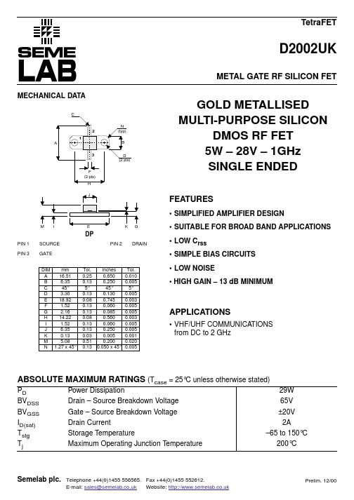
DIM mm A 16.51 B 6.35 C 45° D 3.30 E 18.92 F 1.52 G 2.16 H 14.22 I 1.52 J 6.35 K 0.13 M 5.08 N 1.27 x 45°
Tol. 0.25 0.13 5° 0.13 0.08 0.13 0.13 0.08 0.13 0.13 0.03 0.51 0.13
FEATURES
• SIMPLIFIED AMPLIFIER DESIGN
M
I
E
K
G
• SUITABLE FOR BROAD BAND APPLICATIONS • LOW Crss • SIMPLE BIAS CIRCUITS
DP
PIN 1 PIN 3 SOURCE GATE PIN 2 DRAIN
THERMAL DATA
RTHj–case Thermal Resistance Junction – Case Max. 6.0°C / W
Semelab plc.
Telephone +44(0)1455 556565. Fax +44(0)1455 552612. E-mail: sales@ Website:
PD BVDSS BVGSS ID(sat) Tstg Tj Power Dissipation Drain – Source Breakdown Voltage Gate – Source Breakdown Voltage Drain Current Storage Temperature Maximum Operating Junction Temperature 29W 65V ±20V 2A –65 to 150°C 200°C
元器件交易网
兄弟机床常用代码
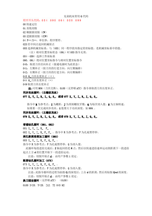
兄弟机床常用G代码程序开头代码:G54G90G64G80G99G0快速定位G1直线切削G2顺圆弧切削(CW)G3逆圆弧切削(CCW)G4 P--/X--,单位秒,程序暂停。
G28经中间点返回机械原点G53选择机械坐标系,与「G53」同一程序段内指定的坐标值,是机械坐标系中的值。
(注)相对位置坐标状态(G91)时G53指令无效。
G54~G59)选择工件座标系G90、G91)绝对位置坐标指令与相对位置坐标指令G40:取消刀具径向补正(接通电源时为此状态)G41:左侧补正(按刀具的行进方向,向左侧偏移)G42:右侧补正(按刀具的行进方向,向右侧偏移)G43 H_刀具长度补正(+)G44 H_刀具长度补正(-)G49取消刀具长度补正注:可用M06(刀具交换)、G100(无停顿ATC)指令来取消刀具长度补正。
同步攻丝循环:(右螺纹攻丝)G77 X_ Y_ Z_ R_ I_ Q_ S_. 或者G77 X_ Y_ Z_ R_ J_ Q_ S_.指令中R为参考点,I为螺距,J为英制螺纹牙数,Q为每次切入量,S为主轴转速。
如果要一次完成同步攻丝,Q值要大于功丝深度,如999.。
同步攻丝循环:(左螺纹攻丝)G78 X_ Y_ Z_ R_ I_ Q_ S_. 或者G78 X_ Y_ Z_ R_ J_ Q_ S_.普通钻孔循环(G81、G82)G81 X_ Y_ Z_ R_ F_ 。
G82 X_ Y_ Z_ R_ P_ F_ 。
指令中R为参考点,P为孔底暂停秒。
深孔断屑排屑加工循环(G83)G83 X_ Y_ Z_ R_ P_ Q_ F_ 。
指令中R为参考点,P为孔底暂停秒,Q为切入量。
此循环每段进给完成后,Z轴返回的是R点,然后以快速进给速率运动到距离下一段进给起点上方d的位置开始下一段进给运动。
注意:切削开始点d,由用户参数1设定。
断屑钻孔循环加工(G73)G73 X_ Y_ Z_ R_ P_ Q_ F_ 。
指令中R为参考点,P为孔底暂停秒,Q为切入量。
DGT系列新版说明书
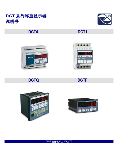
DGT系列称重显示器说明书DGT4 DGT1DGTQ DGTPDGT说明书_07_13.10_CN目录1. 注意事项 (2)2. 规格参数 (3)3. 安装 (4)3.1 DGT4尺寸及接口 (4)3.2 DGT1尺寸及接口 (5)3.3 DGTQ尺寸及接口 (6)3.4 DGTP尺寸及接口 (7)4. 指示灯与键盘 (8)4.1 指示灯 (8)4.2 键盘 (9)5. 开机与关机 (9)6. 启动菜单 (9)6.1 菜单树形图 (9)6.2 菜单选项介绍 (12)6.2.1 <<>> 称重模式 (12)6.2.2 <<>> 称重功能 (13)6.2.3 <<>> 称重显示器配置 (14)6.2.4 <<>> 称重显示器性能配置 (16)6.2.5 <<>> 通讯串口配置 (17)6.2.6 <<>> 诊断菜单 (18)7. 主要功能 (19)8. 串口指令 (19)9. 传输字符串格式 (21)9.1 标准字符串 (21)9.2 扩展字符串 (21)10. Modbus与Profibus通讯参数设置 (22)10.1 Modbus通讯参数设置 (22)10.2 Profibus通讯参数设置 (22)11.电气连接图 (23)11.1 DGT1 (23)11.2 DGT4 (24)11.3 DGTQ (26)11.4 DGTP (28)12. 仪表报错代码 (31)产品适用标准说明 (32)质量保证和授权售后服务中心 (32)1. 注意事项注意为获得最佳称重效果,建议在具备以下条件的场所安装称重显示器和称重模块:∙无振动、粉尘、浓烈的烟雾和气流。
若工作环境比较恶劣,例如:粉尘大、湿气重等,必须在称重显示器外加装一个保护箱,同时保证保护箱密封性良好,避免粉尘或湿气进入称重显示器。
DG470EQ-T1-E3中文资料

Vishay SiliconixDG469/470High Voltage, Single and Dual Supply SPDT Analog Switchwith Enable PinFEATURES•Low on resistance (3.6 Ω typical)•On resistance flatness (0.4 Ω typical) •44 V supply maximum rating •± 15 V analog signal range••TTL/CMOS compatible •Break before make switching guaranteed •Total harmonic distortion 0.0145 %APPLICATIONS•Audio and video signal switching •Precision automatic test equipment •Precision data acquisition •Relay replacement•Communications systems •Automotive applications •Sample and hold systems •Power routing applications •Telecom signal switching •Medical equipment•Portable and battery power systemsDESCRIPTIONThe DG469/470 are high voltage SPDT switches, with a typical on resistance of 3.6 Ω and typical flatness of 0.4 Ω.The DG469 and DG470 are identical, except the DG470provides an enable input. When the enable input is activated,both sides of the switch are in a high impedance mode (Off),maintaining a "Safe State" at power up. This function can also be used as a quick "disconnect" in the event of a fault condition. For audio switching, the enable pin provides a mute function. These are high voltage switches that are fully specified with dual supplies at ± 4.5 V and ± 15 V and a single supply of 12 V over an operating temperature range from - 40 °C to + 125 °C. Fast switching speeds coupled with high signal bandwidth makes these parts suitable for video switching applications. All digital inputs have 0.8 V and 2.4 V logic thresholds ensuring low voltage TTL/CMOS compatibility. Each switch conducts equally well in both directions when on and can handle an input signal range that extends to the supply voltage rails. They exhibit break-before-make switching action to prevent momentary shorting when switching between channels. The DG469 and DG470are offered in a MSOP 8 and SOIC 8 package.FUNCTIONAL BLOCK DIAGRAM AND PIN CONFIGURATIONTRUTH TABLE: DG469Logic NC NO 0ON OFF 1OFFONTRUTH TABLE: DG470ENABLELogic NC NO 00ON OFF 01OFF ON 1XOFFOFFVishay SiliconixDG469/470Notes:a. - 40 °C to 85 °C datasheet limits apply.Notes:a. Signals on S X , D X , or IN X exceeding V+ or V- will be clamped by internal diodes. Limit forward diode current to maximum current ratings.b. All leads welded or soldered to PC Board.c. Derate 4.0 mW/°C above 70 °C.d. Derate 5.0 mW/°C above 70 °C.ORDERING INFORMATIONTemp Range PackagePart NumberDG469/470- 40 °C to 125 °C a8-Pin MSOPDG469EQ-T1-E3DG470EQ-T1-E38-Pin Narrow SOICDG469EY -T1-E3DG470EY -T1-E3ABSOLUTE MAXIMUM RATINGS T A = 25 °C, unless otherwise notedParameter Limit Unit V+ to V- 44VGND to V- 25Digital Inputs a, V S , V D(V-) - 2 to (V+) + 2or 30 mA, whichever occurs firstContinuous Current (NO, NC, or COM)120mA Current (Any terminal except NO, NC, or COM)30Peak Current, (Pulsed 1 ms, 10 % Duty Cycle)200Storage T emperature - 65 to 150°C Power Dissipation (Package)b8-Pin MSOP c 320mW8-Pin Narrow SOIC d400SPECIFICATIONS FOR DUAL SUPPLIESParameter Symbol Test Conditions Unless Specified V+ = 15 V , V- = - 15 V V IN = 2.4 V , 0.8 V a Temp b Typ c - 40 to 125 °C- 40 to 85 °CUnitMin d Max d Min d Max dAnalog Switch Analog Signal Range e V ANALOGFull - 1515- 1515VOn-Resistance r ON I S = 50 mA, V D = - 10 V to + 10 VRoom Full 3.66867ΩOn-Resistance Match Δr ON I S = 50 mA, V D = ± 10 V Room Full 0.120.40.90.40.5On-Resistance Flatness r FLATNESS I S = 50 mA, V D = - 5 V, 0 V , + 5 VRoom Full 0.40.50.90.50.8Switch OffLeakage Current I S(off)V D = ± 14 V , V S = ± 14 VRoom Full ± 0.1- 0.5- 200.520- 0.5- 2.50.52.5nA I D(off)Room Full ± 0.1- 0.5- 200.520- 0.5- 2.50.52.5Channel On Leakage Current I D(on)V S = V D = ± 14 VRoom Full± 0.2- 0.5- 200.520- 0.5- 50.55Digital Control Input Current, V IN Low I IL V IN Under T est = 0.8 V Full 0.05- 11- 11µA Input Current, V IN High I IH V IN Under T est = 2.4 VFull 0.05- 11- 11Input Capacitance eC INf = 1 MHzRoom3.7pFVishay SiliconixDG469/470Dynamic Characteristics T urn-On Time t ON R L = 300 Ω, C L = 35 pFV S = ± 10 V Room Full 129166200166185nsT urn-Off Time t OFF Room Full 80108135108120Break-Before-MakeTime Delay t D V S = 10 VR L = 300 Ω, C L = 35 pF Room 15Charge Injection e Q V g = 0 V , R g = 0 Ω, C L = 1 nFRoom 58pCOff Isolation eOIRR R L = 50 Ω, C L = 5 pFf = 1 MHzRoom - 57dB Channel-to-Channel Crosstalk eX T ALK Room - 63Source Off Capacitance e C S(off) f = 1 MHzRoom 37pF Drain Off Capacitance e C D(off)Room 85Channel On Capacitance e C D(on)Room125Power Supplies Power Supply Current I+V+ = 16.5 V, V- = - 16.5 VV IN = 0 or 5 VRoom Full 3.06767µANegative Supply Current I- Room Full - 0.4- 0.5- 4.5- 0.5- 4.5Ground CurrentI GNDRoom Full- 3.0- 6- 7- 6- 7SPECIFICATIONS FOR DUAL SUPPLIESParameter Symbol Test Conditions Unless Specified V+ = 15 V, V- = - 15 V V IN = 2.4 V , 0.8 V a Temp b Typ c - 40 to 125 °C- 40 to 85 °CUnitMin d Max d Min d Max dSPECIFICATIONS FOR DUAL SUPPLIESParameter Symbol Test Conditions Unless Specified V+ = 4.5 V , V- = - 4.5 V V IN = 2.4 V , 0.8 V a Temp b T yp c - 45 to 125 °C- 40 to 85 °CUnitMin d Max d Min d Max dAnalog Switch Analog Signal Range e V ANALOGFull - 4.54.5- 4.54.5V On-Resistance e r ON I S = 50 mA, V D = - 2 V to + 2 VRoom Full 811161115ΩOn-Resistance Match e Δr ONI S = 50 mA, V D = ± 2 VRoom Full0.60.70.90.70.8Dynamic Characteristics T urn-On Time e t ON R L = 300 Ω, C L = 35 pFV S = 2 V Room Full 24526534065310nsT urn-Off Time e t OFF Room Full 145163200163185Break-Before-Make eTime Delay t D V S = 2 VR L = 300 Ω, C L = 35 pF Room Full 15Charge Injection e QV g = 0 V , R g = 0 Ω, C L = 1 nFFull58pCPower Supplies Power Supply Current e I+V IN = 0 or 4.5 VRoom Full 3.06767µANegative Supply Current e I- Room Full - 0.4- 0.5- 4.5- 0.5- 4.5Ground Current eI GNDRoom Full3.0- 6- 7- 6- 7Vishay SiliconixDG469/470Notes: a. V IN = input voltage to perform proper function.b. Room = 25 °C, Full = as determined by the operating temperature suffix.c. Typical values are for DESIGN AID ONLY, not guaranteed nor subject to production testing.d. The algebraic convention whereby the most negative value is a minimum and the most positive a maximum, is used in this data sheet.e. Guaranteed by design, not subject to production test.Stresses beyond those listed under “Absolute Maximum Ratings” may cause permanent damage to the device. These are stress ratings only, and functional operation of the device at these or any other conditions beyond those indicated in the operational sections of the specifications is not implied. Exposure to absolute maximum rating conditions for extended periods may affect device reliability.SPECIFICATIONS FOR UNIPOLAR SUPPLIESParameter Symbol Test Conditions Unless Specified V+ = 12 V , V- = 0 V V IN = 2.4 V, 0.8 V a Temp b T yp c - 40 to 125 °C- 40 to 85 °CUnitMin d Max d Min d Max dAnalog Switch Analog Signal Range e V ANALOGFull 1212VOn-Resistance r ON I S = 25 mA, V D = 0 V to + 10 V Room Full 7.58.5148.511.3ΩOn-Resistance Match Δr ON I S = 25 mA, V D = + 10 V Room Full 0.40.450.90.450.5On-Resistance Flatness r FLATNESSI S = 25 mA,V D = 0 V , + 5 V , + 10 VRoom Full2.52.62.92.62.8Dynamic Characteristics Turn-On Time t ON R L = 300 Ω, C L = 35 pFV S = 10 V Room Full 190200255200240nsTurn-Off Time t OFF Room Full 100110135110120Break-Before-MakeTime Delay t D V S = 10 VR L = 300 Ω, C L = 35 pF Room 50Charge Injection e QV g = 0 V , R g = 0 Ω, C L = 1 nFRoom2.4pCPower Supplies Power Supply Current I+V IN = 0 or 5 VRoom Full 3.06767µANegative Supply Current I- Room Full - 0.4- 0.5- 4.5- 0.5- 4.5Ground CurrentI GNDRoom Full- 3.0- 6- 7- 6- 7Vishay SiliconixDG469/470TYPICAL CHARACTERISTICSDD Leakage Current vs. TemperatureD DVishay SiliconixDG469/470TYPICAL CHARACTERISTICSCharge Injection vs. Analog VoltageCharge Injection vs. Analog VoltageSwitching Time vs. Temperature andDual Supply VoltageSingle Supply VoltageVishay SiliconixDG469/470TYPICAL CHARACTERISTICSTEST CIRCUITSInsertion Loss, Off-Isolation, Crosstalkvs. FrequencySwitching Threshold vs. Dual Supply VoltageSwitching Threshold vs. Signal Supply VoltageDG469, DG470 Total Harmonic DistortionFigure 1. Switching TimeVishay SiliconixDG469/470New ProductTEST CIRCUITSVishay Siliconix maintains worldwide manufacturing capability. Products may be manufactured at one of several qualified locations. Reliability data for SiliconTechnology and Package Reliability represent a composite of all qualified locations. For related documents such as package/tape drawings, part marking, and reliability data, see /ppg?71470.Figure 2. Break-Before-MakeFigure 3. Charge InjectionFigure 4. Off-Isolation Figure 5. Source/Drain Capacitances元器件交易网Legal Disclaimer NoticeVishayNoticeSpecifications of the products displayed herein are subject to change without notice. Vishay Intertechnology, Inc., or anyone on its behalf, assumes no responsibility or liability for any errors or inaccuracies.Information contained herein is intended to provide a product description only. No license, express or implied, by estoppel or otherwise, to any intellectual property rights is granted by this document. Except as provided in Vishay's terms and conditions of sale for such products, Vishay assumes no liability whatsoever, and disclaims any express or implied warranty, relating to sale and/or use of Vishay products including liability or warranties relating to fitness for a particular purpose, merchantability, or infringement of any patent, copyright, or other intellectual property right.The products shown herein are not designed for use in medical, life-saving, or life-sustaining applications.Customers using or selling these products for use in such applications do so at their own risk and agree to fully indemnify Vishay for any damages resulting from such improper use or sale.元器件交易网。
DG412DY中文资料

• Widest Dynamic Range • Low Signal Errors and Distortion • Break-Before-Make Switching Action • Simple Interfacing
APPLICATIONS
• Precision Automatic Test Equipment • Precision Data Acquisition • Communication Systems • Battery Powered Systems • Computer Peripherals
Logic "0" ≤ 0.8 V Logic "1" ≥ 2.4 V
DG411 ON OFF
DG413
DG413
Dual-In-Line and SOIC
LCC
IN1 1
D1 IN1 NC IN2 D2
Key
16 IN2
3 2 1 20 19
D1 2 S1 3 V- 4 GND 5 S4 6 D4 7 IN4 8
Switch Off Leakage Current
Symbol VANALOG
rDS(on) IS(off) ID(off)
Channel On Leakage Current
Digital Control Input Current, VIN Low Input Current, VIN High Dynamic Characteristics
To achieve high-voltage ratings and superior switching performance, the DG411 series was built on Vishay Siliconix’s high voltage silicon gate process. An epitaxial layer prevents latchup.
数控机床设备资料中英文对照

数控机床设备资料中英文对照一:说明书名词解释:lubrication hole[机]润滑孔; [机]滑油孔; 加油孔; [机]注润滑油孔Pressure Lubrication[机]压力润滑; 强制润滑; [机]加压润滑lubrication device润滑装置; 润滑油; 润滑装配AUTO LUBE 自动润滑Spindle motor 主轴马达Hydraulic pump motor 油压马达Auto Cross feed motor 前后马达High Pressure Through Coolant刀具高压冷却系统once-through coolant system一次流过冷却系统Coolant through spindle油水别离机sp. through coolant主轴通过冷却液through coolant通过冷却剂coolant jet冷却剂喷嘴flood coolant motor洪水冷却电机base coolant/gun motor基地冷却剂/枪电动机mist collect motor雾收集电动机Coolant motor (for tools/chips) 切削水马达Chip conveyor motor 铁屑输送机马达ATC motor 储刀仓马达fan cooler风扇冷却器fan draught cooler冷风机fan cooler(for amp):风扇冷却器〔对放大器〔amplifier〕〕containment fan cooler平安壳风机冷却器fan-draught cooler风扇冷却器fan unit 风扇设备风扇单元风扇装置panel cooling 嵌入式降温panel door 镶板门panel heating 板壁供热tool counter工具柜台MAGAZINE CW 刀库正转MAGAZINE CCW 刀库反转 ...COUNTER 〔计数器〕TOTAL COUNTER〔总计数器〕Mate:配对物〔伴侣〕Rotation:旋转回转Caution:慎重radiator brake:散热器制动air duster blow gun吹尘器喷枪air-blow pipe喷气管Air Blow:鼓风Overload:超载overload protection防止过载,超载防护information overload信息过载;信息超载;信息超负荷overload capacity过载容量overload operation超负荷运行,超载运行thermal overload relay热继电器;热过载继电器overload current[电]过载电流 ; 过载电流过负荷电流dis connect jumper pin in case of using sub op存保方案连接跳线针如果使用子运算〔in case of using如果使用;usb op 子运算〕disconnect jumper pin断开连接跳线针beta-i servo :β-i 伺服spindle amplifer:主轴放大器manual feed delay:手动进给延迟rigid tapping ontime:刚性攻丝准时z-axis cancel:z轴取消Current Tool Number现行刀具号Reset Current Tool恢复当前工具预设servo amp module伺服放大器模块optical fiber cable:光缆、光纤光缆sheet key板键Head sheet Key头型图要点key sheet键盘纸; 转印盘纸i series servo motor:i系列伺服电动机call light:警示灯lub. motor on :润滑泵接通〔lubricant润滑剂motor-on signal马达接通信号ATC forward:ATC 向前ATC reverse :ATC反向Ball screw:滚珠丝杠Binary code :二进制DETACH:别离,脱开Follow-up :位置跟踪Black format:程序段格式Tool post interference check:刀架碰撞检查Abnormal load detection:异常负载检测Manual handle interruption:手轮中断Ladder diagram:梯形图〔阶梯,关系图〕Tool counter:工具柜台Magazine:刀库Brake module:制动模块Machine side:机侧Twist pair:双绞线Main power source:主电源Wiring diagram:接线图Current:现时状态、现行状态Dual table :双工作台Spare:备用件、预置Aux:辅助Brake on:制动器Mist :雾状、雾Coolant tank capacity:冷却泵油箱容量Enclosure:外壳、套、附件Overload:过载Flag:标志Condition:条件Machine ready delay:机床准备延迟Encoder:编码器Etherent:以太网口Orientation:主轴定向Spindle positioning:主轴定位Fault:故障Motion:运转Dwell:停歇,保压Feed rate:进给率Interlock/start-lock:互锁/启动-锁Spindle speed arrival check:主轴速度到达检测concent for maintenance容许为维护AC reactor:交流电抗器APC:绝对位置编码器反应(Absolute position encoder feedback) arm in position z-axis interlock:手臂位置Z轴互锁Pressure:压力,压强,是……压迫Pressure valve[机]压力阀; [机]压力值; 止回阀; [机]回压阀air pressure气压; 空气压力; [建]工作气压; [物]气源压力consuming volume耗用量Oil:油Oller:n. 轮胎式压路机Capacity:n. 能力;容量;资格,地位;生产力bearing capacity[力]承载能力; [力]承载力; [力]承重能力; 支持力oil type 油的类型pumping n. [机] 抽吸;脉动;抽气效应v. 抽水〔pump的ing形式〕pumping out抽空; 扬水; 排出; 泵出pumping frequency[电子]泵频; 抽运频率; 泵送频率interval:间隔间距class interval[统计]组距; 组区间; 级距; 标度分组间隔Time interval[天]时间间隔; [天]时间区间; 时距; [天]时段interval scale[统计]区间尺度; 等距量表; [计]等距尺度; 等距量尺capacity:容量consuming:adj. 消费的;强烈的v. 消耗〔consume的ing形式distributor分配器metering n. 计量,[测] 测量;测光模式v. 以计量器计量〔meter的ing形式metering valve[机]计量阀; 限流阀; [机]限量阀; [机]配量阀metering jet量孔; [油气]测油孔; 计量喷流OPTION:选择〔选择功能块〕ARM:机械手ARM home position:机械手原点位置soft key cable:软键电缆PUNCH PANEL:开孔面板MOTHER BOARD:母版Name:名称Description:描述Connector:连接器Clamp:夹紧Unclamp:松开Lamp:灯noise filter:噪声滤波器二、操作面板中英文对照:ABS和REL——在法那克系统中,按这两个键分别来切换当前机床的相对坐标和绝对坐标ALL——全选,程序编辑时用PRGRM——程序〔program〕的缩写,用于查看程序NEXT——查看程序和查看参数时,下一页OPRT——在法那克系统中,选择编辑程序时,也就是按下PRGRM后,再按这个键,才能输入程序号HOST,CONECT——这两个是在系统与外界通信时用的,我没试过,不知道什么作用HELP——查看帮助信息SHIFT——换档键,有些键有两个字符,按下这个键,用来输入顶部那个字符ALTER——程序修改键,编辑程序时用INSERT——程序插入键,编辑程序时用EOB——程序完毕符,在编辑程序时,没段程序完毕时,要加这个符号CAN——取消键,用来取消输入INPUT——输入键,用来输入程序或参数POS——按此键显示当前机床位置画面PROS——按此键显示当前程序画面OFFSET——按此键显示刀具偏置画面SETTING——按此键显示刀具偏置设定画面SYSTEM——按此键显示系统信息及系统状态画面GRAPH——按此键显示加工时刀具轨迹的图形画面CUSTOM——按此键显示用户宏程序画面手动数据输入(MDI)直接数字控制方法(DNC)控制器单元或机控制器单元〔MCU〕法拉克:ALTER 修改程序及代码INSRT 插入程序DELET 删除程序EOB 完成一句(END OF BLOCK)CAN 取消(EDIT 或MDI MODE 情况下使用)INPUT 输入程序及代码OUTPUT START 输出程序及指令OFFSET 储存刀具长度、半径补当值AUX GRAPH 显示图形PRGRM 显示程序内容ALARM 显示发生警报内容或代码POS 显示坐标DGONS PARAM 显示自我诊断及参数功能RESET 返回停顿CURSOR 光标上下移动PAGE 上下翻页三、机床报警信息中英文对照:T WORD ERROR 〔T 码错误〕LOW OIL LEVEL 〔油位低〕SPINPLE FAULT 〔主轴故障〕SPINDLE ALARM 〔主轴报警〕EXTERNAL EMG STOP 〔急停按钮被按下〕AC NOT READY 〔交流盘未准备好〕SPINPLE LUBE FAULT 〔主轴润滑故障〕T CODE ERROR 〔T代码出错,非法T代码〕M CODE ERROR 〔M代码出错,非法M代码〕SERVO NOT READY 〔伺服未准备好〕NC NOT READY〔NC没准备好〕TURRET FAULT 〔转塔故障〕TURRET LIMIT 〔转塔限位〕DC 24V OPEN 〔直流24断开〕+24V NOT READY〔+24V没准备好〕GRAR DRIFT 〔档位漂移〕PLEASE AXIS RETURN HOME〔轴未回零〕PLEASE DRUM RETURN HOME〔刀库未回零〕AIRPRESSFAILURE〔气压故障〕UNCL TOOL FALL〔松刀失败〕AIR PRESSURE DROP 〔压缩空气压力过低〕CLAMP TOOL FALL〔夹刀失败〕DRUM NOT PARKED〔刀库未在原值〕X ZERO POINT NOT REACHED 〔X 轴未回零〕Y ZERO POINT NOT REACHED 〔Y 轴未回零〕Z ZERO POINT NOT REACHED 〔Z 轴未回零〕4TH ZERO POINT NOT REACHED 〔第4轴未回零〕X AXIS OVERTRAVL〔X轴超限〕Y AXIS OVERTRAVL 〔Y轴超限〕Z AXIS OVERTRAVL 〔Z轴超限〕COUNTER SWITCH REEOR 〔计数开关故障〕MASTERT RANSFER OVER TEMP 〔主变压器过热〕Z AXIS NOT AT FIRST REF POSITION 〔Z轴未在第一参考点〕SPINDLE ORIENTATION FALLURE 〔主轴定向失败〕TOOL DESENT OR TOOL DATA REEOR 〔刀具数据错误〕PLEASE UNLOAD THE TOOL ON SPRINELK 〔请卸下主轴上的刀〕PLEASE LOAD TOOL ON APINDLE 〔请装上主轴上的刀〕A AXIS UNCLAMP FAIL 〔A 轴松开失败〕A AXIS CLAMP FAIL 〔A 轴夹紧失败〕DRUM OUT TO APRONDLEIS FALL 〔刀库摆向换刀位失败〕MG SWING OVERLOAD〔刀库摆动过载〕DRUM BACK PARK IS FALL 〔刀库摆回原始位失败〕TURRENT MOTOR1 OVERLOAD 〔刀库移动电机过载〕COOLANT MOTOR OVERLOAD 〔冷却泵过载〕DRUM ATC FAULT 〔自动换刀失败〕TOOLS UNLOCKED 〔刀具未锁紧〕BATTERY ALARM 〔电池报警〕DRUM POSITION SWITCH ERROR 〔刀库位置检测开关故障〕DRUM NOW NOT AT PARK 〔刀库未在原始位置〕IT DANGOU TO MOVE DRUM 〔刀库禁动〕POT UO FAILOR POT NOT AT UP POSITION 〔刀套未在水平位〕POT DOWN FAIL 〔刀套翻下动作失败〕IT IS DANGOUR TO MOVE ARM 〔机械手禁动〕THE SPINDLE STATU IS ERROR 〔主轴状态错误〕ARM MOTOR OR ARM SWITCH FALL 〔机械手或机械手开关故障〕CENTRE LUBRICATION FALL 〔中心润滑故障〕THE WORK NOT CLAMPED 〔工件未夹紧〕AUTO TOOL CHANGE FAULT 〔自动换刀失败〕TOOL DATA OUT OF RANGE 〔指令刀具号超出范围〕THE ORDER TOOL NOW IN SPINDLE 〔目标刀具在主轴上〕THE THREE SPINDLE SWITCH FAULT 〔主轴上的接近开关〕THE CENTRE COOLANT IS LOWER 〔刀具内冷泵液位过低〕DRUM RETURN 1# POSITION FAULT 〔刀库自动回零失败〕SPINDLE OVERLOAD 〔主轴过载〕TURRENT MOTOR OVERLOAD 〔刀盘转动电机过载〕CHIP CONVEYER OVERLOAD 〔拉屑器过载〕HARD LIMIT OR SERVO ALARM 〔硬限位或伺服报警〕NO LUB OIL 〔无润滑油〕INDEX HEAD UNLOCKED 〔分度头未锁紧〕MT NOT READY〔机床没准备好〕MG OVERLOAD 〔刀库过载〕LUB EMPTY〔润滑无油〕AIR PRESSURE〔气压缺乏〕COOLANT NOT READY〔冷却没准备好〕LUBE EMPTY〔油雾油位低,润滑油位低〕LUB PRESSURE LOW〔润滑压力低〕CONVEY VERLOAD〔排屑过载〕LUB OVERLOAD〔润滑过载〕LUBE PRESSURE LOW〔油雾压力低〕SERIAL SPINDLE ALARM (串行主轴报警)NC BATTERY LOW ALARM(NC电池低报警)MAGAZINE MOVE LIMIT SWITCH ERRORSPINDLE TOOL UNLAMP POSITION LIMIT SWITCH ERROR MAGAZINE NOT IN POSITION OR SENSOR ERRORAIR PRESSURE LOW ALARM(气压低报警)MOTOR OVERLOAD(电机过载)T CODE > MAGAZINE TOOLST CODE < 1 ERROR5TH AXIS HARDWARE OVERTRAVER LIMIT ERRORDOOR IS OPENED(开门)LUB PRESSURE SWITCH ERROR(油压开关错误)SPINDLE OIL COOLANT UNIT ERRORSPINDLE LOAD ABNORMAL〔主轴负荷异常〕TRANSDUCER ALARM〔传感器报警〕BED-HEAD LUBRICATE OFF〔床头润滑关闭〕EMG OFFHYDRAULIC CHUCK PRESS LOW〔液压夹头压力低〕HYDRAULIC TAIL PRESS LOW〔液压尾座压力低〕LUB 0IL LOW〔油压低〕TURRET CODE ERROR〔转塔码错误〕TURRET RUN OVERTIME〔转塔运行超时〕MANUAL HANDLE INTERRUPTTRY TO RUN SPINDLE WHILE CHUCK NOT LOCKTRY TO RUN SPINDLE WHILE TAIL NOT LOCKSPINDLE NEUTRAL GEARMAGAZINE ADJUSTHYDRAULIC NOT RUNSAFETY DOOR BE OPENEDSAFETY DOOR NOT CLOSENOT ALL AXIS HAVE GONE BACK REFIN ADJUST,IGNORE GOING BACK REFAFTER EXCHANGE TOOL,CYCLE STARTATC MOTOR QF16 OFFX AXIS IS LOCKED〔X 轴被锁定〕Y AXIS IS LOCKED〔Y 轴被锁定〕Z AXIS IS LOCKED〔Z 轴被锁定〕A AXIS IS LOCKED〔A 轴被锁定〕SPINDLE MOTOR FAN QF26 OFF(主轴电机风扇QF26关闭) SPINDLE ORIENTATION INCOMPLETE〔主轴定位不完全〕M FUNCTION NOT COMPLETE〔M 功能无法完成〕SPINDLE NOT IN GEAR POSITION〔齿轮不在主轴位置〕SPINDLE NOT CHANGED TO LOW GEAR〔主轴没有变为低档〕SPINDLE NOT CHANGED TO HIGH GRAR〔主轴没有变为高档〕MAG NOT BACKWARDSPINDLE TOOL NOT CLAMPSPINDLE TOOL NOT UNCLAMPMAG NOT IN POSITIONMAG DOES NOT ROTATEMAG DOES NOT STOP RUNNINGA AXIS HAVE NOT CLAMPEDA AXIS HAVE NOT UNCLAMPEDSET D499=1,"MAG.JOG" SWITCH ONHYDRAULIC MOTOR QF7 OFF〔液压马达QF7关闭〕HYDRAULIC TEMPRETURE HIGH〔液压使用温度高〕HYDRAULIC FILTER BLOCKED〔液压过滤器阻止〕HYDRAULIC OIL LEVEL LOW〔液压油位低〕HYDRAULIC FAN QF8 OFF〔液压风扇QF8关闭〕HELIX CONYER QF9 OR QF10 OFFCHAIN CONYER QF11 OFFCOOLANT MOTOR QF12 OFF〔冷却液电机QF12关闭〕COOLNT LEVEL LOW,CYCLE STOP AFTER 20 MINUTESINNER COOLANT BLOCK〔内冷却堵塞〕SPINDLE COOLANT MOTOR QF14 OFF〔主轴冷却液电机QF14关闭〕INNER COOLANT QF13 OFF〔内冷却液QF13关闭〕MAG MOTOR QF15 OFFCABINET COOLANT EQUIP QF20 OFFOIL GATHER QF24 OFFAIR PRESSURE LOW〔低气压〕SPINDLE COOLANT MOTOR FAULT〔主轴冷却液电机故障〕LUB.OIL IS LOW〔润滑油低〕DOOR OPEN〔门翻开〕FRONT DOOR(R) OPEN〔前门翻开〕LEFT DOOR OPEN〔左门翻开〕LUBRICATION OIL QF23 OFF〔润滑油QF23关闭〕LUBRICATION PRESS LOW〔润滑油位低〕IN ADJUST,MAG CAN'T EXCHANGE T〔在调整,刀库不能交换T〕NOT ALL DOOR CLOSED〔门没有全部关闭〕IN M06,MAG NOT READY〔在M06,刀库未准备好〕MAGAZINE NOT READY〔刀库未准备好〕POCKET NOT HORIZANTALIN M06,Z NOT BACK TO 2ND REFIN M06,Z AXIS NOT IN PSW1ATC NOT IN ZERO POSITIONSPINDLE ORIENTATION UNCOMPLETEPOCKET NOT HOR./MAG NOT BCKWRDPOCKET NOT VER./MAG NOT FORWRDUNCLAMP TOOL HAS NOT COMPLETEDCLAMP TOOL HAS NOT COMPLETEDAIM TOOL NO. IS WRONGMAG NOT BACKWARDAFTER RETRACT,SET R.T.BACK OFFZ NOT IN PSW2,FORBID ATC RUNNINGD499 EQUAL 1MAG.JOG SOFT SWITCH IS ONZ NOT IN PSW2,FORBID MAG FORWARDCHEKE SPINDLE MODULE ALARMOIL WATER SEPARATOR QF24 OFFSET THE SOFT SWITCH MAG.JOG OFFSET D499 TO 0 设定D499为0K PARAM ABOUT MAG SET IS WRONG 关于MAG的K参数设定错误MECHANICAL BRAKE NOT RELEASED机床抱闸没有松开MECHANICAL BRAKE IS WRONG 机床抱闸错误PLEASE ADD LUB.OIL 请加润滑油PROBE BATTERY VOLTAGE IS LOW 探头电池电压低PROBE IS ERR 探头错误PARAMETER WRITE ENABLE〔参数写使能〕PMC EDIT ENABLE〔PMC编辑使能〕CHECK LUB ROUTINSPINDLE GEAR SIGNAL MISS 主轴档位信号消失T_CLAMPED_SIGNAL MISS T夹紧信号消失SP OVERRIDE SWITCH DISCONNECTION 主轴倍率开关断路FEED OVERRIDE SWITCH DISCONNECTION 进给倍率开关断路THE TOTAL NUMBER OF POCKETS SET ERRCHANGE T STOPED BECAUSE NO AIR 因为缺少压空交换停顿THE COOLANT WATER TOO LOW,ADD COOLANT WATER AT ONCE 冷却水少立即加水COOLANT LEVEL LOW,ADD COOLANT WATER 冷却水液位低PLEASE REPLACE CNC BATTERY QUICKLY 请立即更换CNC电池四、SIEMENS常用缩略语:SIEMENS常用缩略语A Output 输出ASCII American Standard Code for Information Interchange 美国信息交换标准代码AV Preparation for work 运行准备BA Operating mode 运行方式BAG Operating mode groups 运行方式组BB Ready for operation 准备好运行BCD Binary Coded Decimals 二-十进制BHG Hand-held terminal 手提终端BOF User interface 用户接口CNC Computerized Numerical Control 计算机化数字控制CP Communication Processor 通迅处理器CPU Central Processing Unit 计算机中央处理装置CR Carriage Return 托架折回CSB Central Service Board(PLC module) 中央维护板,PLC 模块CTS Clear To Send 发送使能DAU Digital-Analog Converter 数模转换器DB Data Block 数据块DIN German Industrial Standards 德国工业标准DIO Data Input/Output 数据输入/输出DRF Differential Resolver Function 差分功能DRY Dry Run 空运行DSB Decoding Single Block 译码单段DSR Data Send Ready 备用输入DW Data Word 数据字E Input 输入EIA-Code Special tape code,number of holes per characters always odd 特殊纸带码,每个字符的孔数为奇数EPROM Programm memory with fixed program 有固定程序的程序存储器E/R Controlled Supply and Energy Recovery Module 可控电源和能量恢复模块ETC ETC key:Extension of the softkey bar in the same menuETC 键:同级菜单扩展键FDB Product designation database 产品指定数据库FIFO First in First Out 先进先出FRA Frame module 帧频模块FRAME Coordinate conversion with the components zerooffset,rotation,scaling,mirror-imaging 坐标换算,具有零点偏置,坐标旋转,标度功能和镜向功能FRK Cutter radius compensation 铣刀半径补偿FST Feed Stop 停顿进给GUD Global User Data 全体用户数据HMS High-Resolution Measuring System 高分辨率测量系统HSA Main Spindle Drive 主轴驱动HW Hardware 硬件IM Interface Module 接口模块IM-S/R Interface Module(S=send/R=receive) 接口模块,S=发送/R=接收INC Increment 步进增量ISO-Code Special tape code,number of holes per character always even特殊纸带码,每个字符的孔数为偶数K1...k4 Channel 1 to Channel 4 通道1 到通道4KOP Ladder Diagram 梯形图KV Loop-Gain Factor 增益系数KUE Transformation Ratio 传动比LCD Liquid Crystal Display 液晶显示LED Light Emitting Diode 发光二极管显示LUD Local User Data 局部用户数据MB Megabyte 兆字节MD Machine Data 机床数据MK Measuring Circuit 测量回路MDA Manual Data Automatic 手动输入,自动执行MLFB Machine-readable product designation 机器可识别的产品代号MMC Man Machine Communication:User interface of the numerical control system for operation,programming and simulation 人机通讯:系统操作界面,用操作,编程和模拟MPF Main Program File:NC part program(main program)NC 零件程序,主程序MPI Multi Point Interface 多点通讯接口MSTT Machine control panel 机床控制面板NC Numerical Control 数字控制NCK Numerical Control Kernel(numerical krnel with block preparation, traversing range etc.) 数字控制核心:具有程序段预处理,运行范围等等NCU Numerical Control Unit 数控单元NURBS Non Uniform Rational B Spline 非均值有理B样条NV Zero Offset 零点偏置OEM Original Equipment Manufacturer 原设备制造商OP Operator Panel 操作面板OPI Operator Panel Interface 操作面板接口PC Personal Comprter 个人计算机PCMCIA Personal Computer Menory Card International Association 接口协议PG Programming Device 编程器PLC Programmable Logic Control 可编程逻辑控制器PRT Program Test 程序测试RAM Random Access Memory 随机存取存储器RISC Reduced Instruction Set Computer 处理器,具有指令组小、通过能力强ROV Rapid Override 快速修调RPA R Parameters Active(NCK memoty area for R parameter numbers)R 参数有效,NCK 中用于R 参数号的存储器区RTS Request To Send(control signal from serial data interfaces)发送请求:来自串行接口的控制信号SBL Single Block 单段SBL2 Single Block Decoding 译码单段SEA Setting Data Active(memory area for setting data in NCK)设定数据有效:用于NCK 中设定数据的存储区SD Setting Data 设定数据SKP Skip Block 程序段跳跃SM Signal Module 信号模块SPF Sub Program File 子程序文件SPS Programmable Logic Controller 可编程逻辑控制器SRK Cutter Radius Compensation 刀尖半径补偿SSFK Leadscrew Error Compensation 丝杠螺距误差补偿SSI Serial Synchronous Interface 串行同步接口SW Software 软件TEA Testing Data Active(with reference to the machine data) 测试数据有效:与机床数据有关TO Tool Offset 刀具补偿TOA Tool Offset Active(memory area for tool offset) 刀具补偿有效,用于刀补的存储区TRANSMIT Transform Milling into Turning(coordinate conversion onturning machines for milling)铣床转换为车床:车床坐标换算用于铣削加工VSA Feed drive(spindle) 主轴进给驱动V Bit type PLC variable PLC变量类型:位VB Byte type PLC variablePLC变量类型:字节WKZ Tool 刀具WZ Tool 刀具WZK Tool offset 刀具补偿ZOA Zero Offset Active(memory area for zero offsets) 零点偏置有效:零点偏置存储区五、常用缩写:启动start STRT停顿stop ST运行run正转forward FWD反转reverse REV加速accelerate减速reduce RED低速low L中速medium M高速high H主轴方向spindle direction向前forward FWD向后backward向左left L向右 right R诊断:DGNOS信息:MSG操作员:OPER参数:PARAM目录:DIR取代:ALTER公共地线,公共线:COM六、知识补充:金属切削 metal cutting机床 machine tool金属工艺学 technology of metals刀具 cutter摩擦 friction联结 link传动 drive/transmission轴 shaft弹性 elasticity频率特性 frequency characteristic 误差 error响应 response定位 allocation机床夹具 jig动力学 dynamic运动学 kinematic静力学 static分析力学 analyse mechanics拉伸 pulling压缩 hitting剪切 shear扭转 twist弯曲应力 bending stress强度 intensity三相交流电 three-phase AC磁路 magnetic circles变压器 transformer异步电动机 asynchronous motor几何形状 geometrical精度 precision正弦形的 sinusoid交流电路 AC circuit机械加工余量 machining allowance 变形力 deforming force变形 deformation应力 stress硬度 rigidity热处理 heat treatment退火 anneal正火 normalizing脱碳 decarburization渗碳 carburization电路 circuit半导体元件 semiconductor element 反应 feedback发生器 generator直流电源 DC electrical source门电路 gate circuit逻辑代数 logic algebra外圆磨削 external grinding内圆磨削 internal grinding平面磨削 plane grinding变速箱 gearbox离合器 clutch绞孔 fraising绞刀 reamer螺纹加工 thread processing螺钉 screw铣削 mill铣刀 milling cutter功率 power工件 workpiece齿轮加工 gear mechining齿轮 gear主运动 main movement主运动方向 direction of main movement进给方向 direction of feed进给运动 feed movement合成进给运动 resultant movement of feed合成切削运动 resultant movement of cutting合成切削运动方向 direction of resultant movement of cutting 切削深度 cutting depth前刀面 rake face刀尖 nose of tool前角 rake angle后角 clearance angle龙门刨削 planing主轴 spindle主轴箱 headstock卡盘 chuck加工中心 machining center车刀 lathe tool车床 lathe钻削镗削 bore车削 turning磨床 grinder基准 benchmark钳工 locksmith锻 forge压模 stamping焊 weld拉床 broaching machine拉孔 broaching装配 assembling铸造 found流体动力学 fluid dynamics流体力学 fluid mechanics加工 machining液压 hydraulic pressure切线 tangent机电一体化 mechanotronics mechanical-electrical integration 气压 air pressure pneumatic pressure稳定性 stability介质 medium液压驱动泵 fluid clutch液压泵 hydraulic pump阀门 valve失效 invalidation强度 intensity载荷 load应力 stress平安系数 safty factor可靠性 reliability螺纹 thread螺旋 helix键 spline销 pin滚动轴承 rolling bearing滑动轴承 sliding bearing弹簧 spring制动器 arrester brake十字结联轴节 crosshead联轴器 coupling链 chain皮带 strap精加工 finish machining粗加工 rough machining变速箱体 gearbox casing腐蚀 rust氧化 oxidation磨损 wear耐用度 durability随机信号 random signal离散信号 discrete signal超声传感器 ultrasonic sensor集成电路 integrate circuit挡板 orifice plate剩余应力 residual stress套筒 sleeve扭力 torsion冷加工 cold machining电动机 electromotor汽缸 cylinder过盈配合 interference fit热加工 hotwork摄像头 CCD camera倒角 rounding chamfer优化设计 optimal design工业造型设计 industrial moulding design 有限元 finite element滚齿 hobbing插齿 gear shaping伺服电机 actuating motor铣床 milling machine钻床 drill machine镗床 boring machine步进电机 stepper motor丝杠 screw rod导轨 lead rail组件 subassembly可编程序逻辑控制器 Programmable Logic Controller PLC 电火花加工 electric spark machining电火花线切割加工 electrical discharge wire - cutting 相图 phase diagram热处理 heat treatment固态相变 solid state phase changes有色金属 nonferrous metal陶瓷 ceramics合成纤维 synthetic fibre电化学腐蚀 electrochemical corrosion车架 automotive chassis悬架 suspension转向器 redirector变速器 speed changer板料冲压 sheet metal parts孔加工 spot facing machining车间 workshop工程技术人员 engineer气动夹紧 pneuma lock数学模型 mathematical model画法几何 descriptive geometry机械制图 Mechanical drawing投影 projection视图 view剖视图 profile chart标准件 standard component零件图 part drawing装配图 assembly drawing尺寸标注 size marking技术要求 technical requirements刚度 rigidity内力 internal force位移 displacement截面 section疲劳极限 fatigue limit断裂 fracture塑性变形 plastic distortion脆性材料 brittleness material刚度准那么 rigidity criterion垫圈 washer垫片 spacer直齿圆柱齿轮 straight toothed spur gear 斜齿圆柱齿轮 helical-spur gear直齿锥齿轮 straight bevel gear运动简图 kinematic sketch齿轮齿条 pinion and rack蜗杆蜗轮 worm and worm gear虚约束 passive constraint曲柄 crank摇杆 racker凸轮 cams共轭曲线 conjugate curve范成法 generation method定义域 definitional domain值域 range导数\\微分 differential coefficient求导 derivation定积分 definite integral不定积分 indefinite integral曲率 curvature偏微分 partial differential毛坯 rough游标卡尺 slide caliper千分尺 micrometer calipers攻丝 tap二阶行列式 second order determinant逆矩阵 inverse matrix线性方程组 linear equations概率 probability随机变量 random variable排列组合 permutation and combination气体状态方程 equation of state of gas动能 kinetic energy势能 potential energy机械能守恒 conservation of mechanical energy 动量 momentum桁架 truss轴线 axes余子式 cofactor逻辑电路 logic circuit触发器 flip-flop脉冲波形 pulse shape数模 digital analogy液压传动机构 fluid drive mechanism机械零件 mechanical parts淬火冷却 quench淬火 hardening回火 tempering调质 hardening and tempering磨粒 abrasive grain结合剂 bonding agent砂轮 grinding wheel。
GD2000-管道杂项组件

单级节流杆 单级节流杆 单级节流杆 单级节流杆 单级节流杆 单级节流杆
启动疏水或其它降压系统 启动疏水或其它降压系统 启动疏水或其它降压系统 启动疏水或其它降压系统 启动疏水或其它降压系统 启动疏水或其它降压系统
指针型三向位移指示器 光电型三向位移指示器
水流指示器 水流指示器 水流指示器 水流指示器 水流指示器 水流指示器 水流指示器 水流指示器 水流指示器 水流指示器 水流指示器 水流指示器 水流指示器
管道杂项组件编制说明
1 疏水管用多级节流孔板
多级节流孔板用于蒸汽管道经常疏水,根据《管规》DL/T5054-1996,亚临界和超临界
参数机组的经常疏水都采用疏水阀。超高压及以下参数机组采用多级节流孔 板,因此此
次修编多级节流孔板在原《87 典管》的基础上,取消亚临界参数系列,增加次高压参数
系列。疏水管用多级节流孔板在原来《87 典管》的基础上局部改进,将两级之间的连接
次高压锅炉汽包安全阀消音器 次高压锅炉汽包安全阀消音器 次高压锅炉过热器安全阀消音器 次高压锅炉过热器安全阀消音器
中压锅炉汽包安全阀消音器 中压锅炉汽包安全阀消音器 中压锅炉过热器安全阀消音器 中压锅炉过热器安全阀消音器
- 444 -
管道杂项组件编制说明 管道杂项组件编制说明
13 MN1.6C12W400A 14 MN1.6C12W450 15 MN1.6C12W450A 16 MN1.6C12W500 17 MN1.6C12W500A
蠕胀测点及监察段
1
MEB
2
MEA
串联阀中间垫圈组件
1
MB10C12M
PN10
Q215-A Q215-A Q215-A Q215-A Q215-A
DORNA东菱伺服基础技术手册上
DORNA东菱伺服基础技术手册上交流全数字伺服驱动器EPS系列基础技术手册l非常感谢您选购EPS系列交流伺服驱动器l在您使用驱动器之前,请仔细阅读本技术手册,按照手册上的规范操作安全注意事项1安全注意事项(使用前请仔细阅读)在产品的安装、运行、维护和检查前请仔细阅读本技术手册,在熟悉了有关设备的知识、安全信息和全部注意事项后再使用本产品。
请将此技术手册妥善保存,以备随时查阅。
如果您不能解决产品出现的问题,请及时联系我们。
n 由于产品的改进,手册内容可能变更,恕不另行通知。
n 在未得我公司授权下,用户对产品的改动我公司将不承担任何责任,产品的保修将因此作废。
注意下列警告,以免伤害人员、防止器件损坏。
n 下面的“危险”和“警告”符号是按照其事故危险的程度标出的危险指示一个潜在的危险情况,如果使用不当,会产生危险状况,有导致人员重伤甚至死亡的可能。
警告指示一个潜在的危险情况,如果使用不当,可能会产生危险状况,有导致人员受到中等程度伤害或轻伤的可能,或者发生物件损坏。
n 下列符号表示哪些是禁止的操作,哪些是必须遵守的。
安全注意事项2警告目录目录第一章功能和构成 (3)1.1EPS系列驱动器技术规格 (3) 1.2EPS系列驱动器功能 (4)1.3EPS系列驱动器命名规则 (5)1.4EPS系列驱动器外形尺寸 (6)1.5EPS系列驱动器适配电机 (14)1.6各部分名称 (17)第二章安装 (19)2.1环境条件 (19)2.2驱动器安装场合 (19)2.3安装方向和间隔 (20)2.4电机的安装 (21)2.5伺服驱动器安装示意图 (21)2.6电缆应力 (22)第三章接线 (23)3.1伺服驱动器与外围设备的连接及构成 (23) 3.2标准接线 (24)3.4编码器信号端子CN3 (32)3.5I/O接口原理 (34)3.6电源系统电路 (38)第四章参数 (39)4.1参数功能 (39)第五章监控与操作 (49)5.1面板操作 (49)5.2监视方式(DISP) (50)5.3参数设置(SET-P) (53)1目录5.4参数管理(EEPOP) (53)5.5速度试运行 (55)第六章报警与处理 (57)6.1驱动器报警 (57)6.2报警处理 (58)第七章伺服电机 (63)7.1型号命名 (63)7.2电机安装尺寸 (77)附录 (84)2第二章安装3第一章功能和构成1.1 EPS 系列驱动器技术规格表1.1 驱动器技术规格控制回路电源单相AC220V-15~+10% 50/60Hz主回路电源三/单相AC220V -15~+10% 50/60Hz环境温度工作:0~55 ℃存贮:-20℃~80℃ 湿度小于90%(无结露)振动小于0.5G(4.9m/S 2),10~60Hz (非连续运行)控制方式IGBT PWM 正弦波控制控制模式①位置控制②速度控制③转矩控制④位置/速度控制⑤位置/转矩控制⑥速度/转矩控制⑦内部位置控制⑧内部速度控制⑨内部转矩控制⑩试运行控制控制输入①伺服使能②报警清除③位置偏差清零④指令脉冲禁止CCW ⑤驱动禁止CW ⑥驱动禁止⑦控制方式选择⑧零速箝位控制输出①伺服准备好②伺服报警③机械制动释放④位置/速度到达⑤零速检出⑥转矩限制中Z ⑦相输出编码器反馈 2500p/r ,15线增量型,差分输出500 p/r ,15线增量型,差分输出通讯方式RS232 RS485 ①②显示与操作①5位LED 显示4②个按键制动方式通过内置/外接制动电阻能耗制动冷却方式风冷(热传导膜具、高速强冷风扇)适配电机可通过参数设置适配不同型号电机功率范围≤22KW第二章安装41.2 EPS 系列驱动器功能表1.2 驱动器功能一览表控制功能位置控制外部输入脉冲形式脉冲/方向,CW/CCW ,A/B 两相最大指令脉冲频率500Kpps (差分输入)电子齿轮1/1800~1800(推荐:1/50~50)脉冲输入指令禁止信号位有效时,指令脉冲输入被禁止;可通过参数屏蔽此信号内部位置指令 8种位置设定速度控制外部速度指令0~±10V DC零速钳位通过此功能使得速度保持为0 速度控制范围1~3000内部速度指令3种速度设定转矩控制外部转矩指令 0~±10V DC 内部转矩指令3种转矩设定转矩控制范围外部转矩指令:0~300% 内部转矩指令:0~300%驱动禁止当CCWL/CWL 信号有效时,电机在CCW/CW 方向输出零速保持力矩监视功能转速、当前位置、指令脉冲积累、位置偏差、电机转矩、电机电流、转子位置、指令脉冲频率、运行状态、输入输出端子信号等保护功能过压、欠压、过流、过速、过载、Z 脉冲丢失、编码器出错、EEPROM 错误、位置超差等报警功能工作异常时输出报警号,同时5个LED 小数点位闪烁信号显示在显示部分显示外部输入、输出信号的ON/OFF 状态增益调整在电机运行或停止时改变增益以调节驱动器性能报警记录可记忆包括当前报警在内的4个报警记录第二章安装产品代号:T 表示通用型、H 表示横机专用型、W 表示袜机专用型、K表示数控专用型 E 表示经济型、G 表示高性能型硬件版本:版本A、版本B…额定功率:1. 功率的位数增加到4位,单位为KW。
高真空单辊旋淬喷铸及熔体抽拉物料进给联合系统技术Ⅰ单
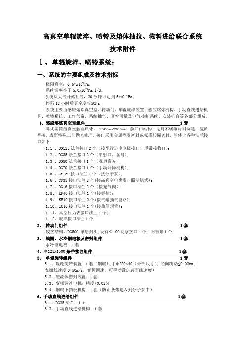
高真空单辊旋淬、喷铸及熔体抽拉、物料进给联合系统技术附件Ⅰ、单辊旋淬、喷铸系统:一、系统的主要组成及技术指标极限真空:6.67x10⁻⁵Pa。
系统漏率小于5.0x10⁻⁸Pa.l/S。
系统从大气开始抽气,20分钟可达到5x10⁻³ Pa;停泵12小时后真空度≤50Pa系统主要由感应熔炼真空室、转动门、单辊旋淬装置、感应熔炼机构、手动直线进给机构、喷铸系统、工作气路、系统抽气、真空测量及电气控制系统、安装机台等各部分组成。
1、感应熔炼真空室组件 1套卧式圆筒型真空腔室尺寸:φ500mmX300mm,前开门结构,选用不锈钢材料制造,氩弧焊接,表面特殊工艺抛光处理,接口采用金属垫圈密封或氟橡胶圈密封,腔体上各种法兰接口如下:1.1、DG125法兰接口2个(接平行进电电极接口、甩带接收口);1.2、DG35法兰接口2个(喷射口、备用);1.3、DG80法兰接口1个(观察窗);1.4、DG70法兰接口1个(手动升降机构);1.5、CF150接口法兰1个(接分子泵);1.6、CF35接口法兰2个(接高真空电离规、照明烘烤);1.7、DG16接口法兰2个(接充气阀);1.8、 KF40接口法兰1个(接旁抽);1.9、 KF10接口法兰2个(接气罐抽气管路);1.10、ZC16接口法兰1个(接热偶规管);1.11、真空压力表接口法兰1个;1.12、旋淬接口法兰1个;2、转动门组件 1套铰接结构,DG500,单层封头,设有Φ100观察接口1个, 衬玻璃1个;3、线圈、水冷铜电极及密封组件 1套水冷铜电极:1套4、Φ125X1500条带接收组件 1套5、单辊旋转组件 1套5.1、辊轮旋转装置:1套(铜辊尺寸φ220×40(外部尺寸);径向跳动≤0.02mm;表面线速度0-50m/s,变频调速,可手动设定表面线速度)5.2、磁流体密封装置:1套5.3、变频调速电机:精度±0.02%5.4、铜辊下挡板机构:1套(防止条带进入到分子泵中)6、手动直线进给组件 1套6.1、DG25法兰:1个6.2、手动直线进给机构:1套6.3、喷射管路:1套7、感应线圈及石英管卡具 1套感应熔炼10克纯铁样品,在30秒钟内熔化;单辊旋淬石英熔炼坩埚加热区:约φ15mm×50mm;8、窗口及法兰接口部件8.1、φ100观察窗装置:1套8.2、φ80观察窗装置:1套8.3、CF35陶瓷封接引线法兰(照明及内烘烤引线):1个9、真空喷铸装置 1套提供标准喷铸模具Φ120X90(内尺寸由客户选定):1套10、工作气体气路 2条10.1、DG16角阀、φ6管路、接头:1路10.2、DG16角阀、管路、接头(解除真空冲氮气):1路11、抽气机组及阀门、管道 1套11.1、工作本底真空获得: 分子泵+机械泵11.1.1、复合分子泵及变频控制电源:1台(抽速600升/秒,北京);11.1.2、2XZ-8直联机械泵:1台(抽速8升/秒,上海);11.1.3、CF150-B闸板阀:1台(用于分子泵与真空室隔离);11.1.4、分子泵与机械泵软联接金属软管:1套11.1.5、KF40电磁隔断放气阀(上海):1台11.2、工作排气获得11.2.1、机械泵与真空室之间的旁抽管路、角阀门:1套11.2.2、KF40电磁隔断阀(北京):1套11.2.3、真空压力表(沈阳):1套11.3、储气罐系统11.3.1、GDC-10电磁阀:3台11.3.2、储气罐φ120×400:1台11.3.3、抽气管路:1套11.3.4、真空压力表(沈阳):1套12、真空测量及电控系统配套电源12.1、宽量程数显真空计(成都):1套热偶规:1套(1.0x105Pa~1.0x10-1Pa);电离规:1套(1.0x10-1Pa~1.0x10-5Pa);12.2、超音频电源(35KW/30-20KHz):1套(用于感应熔炼合金样品)12.3、分子泵控制电源:1套12.4、变频调速电机及电源:1套12.5、电源机柜:1.6米:1台自制电源12.6、总控制电源,为机械泵、真空计等提供电源:1台有断电断水保护功能。
新代程式说明书
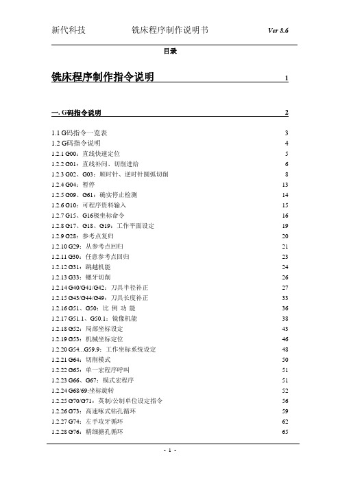
目录铣床程序制作指令说明 1一. G码指令说明 21.1G码指令一览表3 1.2 G码指令说明4 1.2.1G00:直线快速定位5 1.2.2G01:直线补间、切削进给6 1.2.3G02、G03:顺时针、逆时针圆弧切削8 1.2.4G04:暂停13 1.2.5G09、G61:确实停止检测14 1.2.6G10:可程序资料输入15 1.2.7G15、G16极坐标命令16 1.2.8G17、G18、G19:工作平面设定19 1.2.9G28:参考点复归20 1.2.10G29:从参考点回归21 1.2.11G30:任意参考点回归23 1.2.12G31:跳越机能24 1.2.13G33:螺牙切削26 1.2.14G40/G41/G42:刀具半径补正27 1.2.15G43/G44/G49:刀具长度补正33 1.2.16G51、G50:比例功能36 1.2.17G51.1、G50.1:镜像机能38 1.2.18G52:局部坐标设定43 1.2.19G53:机械坐标定位46 1.2.20G54...G59.9:工作坐标系统设定48 1.2.21G64:切削模式50 1.2.22G65:单一宏程序呼叫51 1.2.23G66、G67:模式宏程序51 1.2.24G68/69:坐标旋转52 1.2.25G70/G71:英制/公制单位设定指令56 1.2.26G73:高速啄式钻孔循环59 1.2.27G74:左手攻牙循环62 1.2.28G76:精细搪孔循环651.2.29G81:钻孔循环68 1.2.30G82:孔底暂停钻孔循环70 1.2.31G83:啄式钻孔循环72 1.2.33G85:钻孔循环78 1.2.34G86:高速钻孔循环80 1.2.35G87:背面精细搪孔循环82 1.2.36G88:半自动精细搪孔循环85 1.2.37G89:孔底暂停搪孔循环87 1.2.38G90/G91:绝对/增量指令89 1.2.39G92:绝对零点坐标系统设定90 1.2.40G94/G95:进给量单位设定91 1.2.41G96/G97:等表面线速度控制92 1.2.42G134:圆周孔循环93 1.2.43G135:角度直线孔循环94 1.2.44G136:圆弧孔循环95 1.2.45G137.1:棋盘孔循环96 1.2.46刀具机能:T码指令97 1.2.47主轴转速机能:S码指令971.2.48进给机能:F码指令97二、M码指令说明:98铣床程序制作指令说明一.G码指令说明1.1G码指令一览表※SYNTEC 900M G code 采用国际通用RS274D 规格,与FANUC 0M 规格唯一差异是G70,G71(公,英制)相对G20,G21G 码指令说明1.2.1 G00:直线快速定位 (POSTIONING)指令格式:G00 X Y Z ;X 、Y 、Z :指定点坐标说明:各轴以最短距离在无切削状态下快速移动至指定点,X 、Y 、Z 为终点的坐标,以G90/G91决定绝对或是增量值。
D2002E技术手册(地磅秤)

宁波柯力电气制造有限公司数字传感器及其称重显示器(D2002E型)技术手册2007年4月版目录第一章概述 (2)一、数字传感器基本工作原理二、称重显示器原理三、系统特点四、数字传感器与仪表通讯格式第二章技术参数 (3)一、数字传感器技术指标二、D2002E型称重显示器技术指标第三章安装连接 (5)一、仪表前视图和后视图二、传感器与仪表的连接三、打印机与仪表的连接四、大屏幕与仪表的连接使用五、串行通讯接口第四章查看传感器内码 (12)第五章角差调整 (13)一、手动方式二、自动方式(四角自动调整)第六章标定 (15)第七章修改传感器地址 (20)第八章秤体线性校正功能设置 (21)第九章安装调试 (22)一、秤台和传感器的安装二、仪表参数设定三、秤台的安装调整四、四角误差调整五、标定第九章操作方法 (24)一、开机及开机自动置零二、手动置零(半自动置零)三、去皮功能操作四、日期与时间的设置及操作五、数据记录的贮存操作六、称重数据的删除七、日报表打印八、注意事项第十章常见故障与解决方法 (27)第十一章维护保养及注意事项 (30)第一章概述一、数字传感器基本工作原理数字式传感器系统,是在传统电阻应变式传感器基础上,结合现代微电子技术,微型计算机技术的集成而发展起来的一种新型的电子称重技术。
它是由模拟传感器(电阻应变式)和数字化转换模块两部分组成,数字模块由高度集成化的电子电路,采用SMT表面贴装技术制成,主要包括:放大器、“A/D”转换器,微处理器(CPU)、存贮器(E2prom)、接口电路(RS485)和数字化温度传感器等组成。
二、数字式称重显示器原理采用RS485接口与数字式称重传感器实现通讯,目前最多可外接10只数字式称重传感器(超过10只时,请及时与本公司联系进行定制),可进行手动/自动偏载调节(四角调整),可自动对单只传感器寻址并读取数据,可现场自动修改传感器编号。
可以实现对数据的处理,如:显示、标定、发送、存储、打印等功能。
新时达一体机资料

1.主板端口定义
控制回路端子排列见图3.17控制回路端子所示。
图3.17 控制回路端子
1.1 输入输出接口定义
序号
位置 名称 定义
类型 备注 JP1
1.
J
P1.1
X0
检修信号1,断开为检修,X0和X1全接通为自动
Input
JP1.2 X1 检修信号2,断开为检修,X0和X1全接通为自动
Input JP1.3 X2 上行信号,检修:点动上行;司机:上行换向 Input JP1.4
X3
下行信号,检修:点动下行;司机:下行换向
Input
低压光耦隔离输入
高压光耦隔离输入 可编程继电器输出
编码器信号输入接口 (冗余) PG 卡分频信号输出
输入输出24V 隔离电源控制输入
CAN 通讯 接口
系统 保留 端口
Modem 远程监控接口
手持操作器接口/小区监控接口
2.主板参数一览表
故障代码及分析表9.1:。
新时达一体机最新参数表

新时达一体机最新参数表新时达一体机最新参数表新时达一体机最新参数表参数号参数名称出厂设定范围单位备注F00 加速斜率550 200-1500 mm/s2 0.55m/ s2 F01 减速斜率550 200-1500 mm/s2 0.55m/ s2F02 S曲线T0(启动初S弯角时间T0)1300 300-3000 ms 1.300sF03 S曲线T1(加速末S弯角时间T1)1100 300-2000 ms 1.100sF04 S曲线T2(减速初S弯角时间T2)1100 300-2000 ms 1.100sF05 S曲线T3(减速末S弯角时间T3)1300 300-3000 ms 1.300sF06 电梯额定速度1750 200-6000 mm/s 1.75m/s F07 电梯额定转速1450 10-10000 rpm 1450rpm F08 编码器每转脉冲数1024 100-10000 ppr 1024ppr F09 锁梯基站 1 1-64F10 偏置实层数0 0-64F11 预设总层数18 2-64F12 检修速度250 0-500 mm/s 0.25m/s F13 返平层速度60 10-150 cm/s 0.06m/sF14 关门延时1(响应召唤时)30 0-300 0.1s 3.0sF15 关门延时2(响应指令时)30 0-300 0.1s 3.0sF16 开闸延时 2 0-20 0.1s 0.2s F17 去除运行延时 6 2-30 0.1s 0.6s F18 消防基站 1 1-64F19 第二消防基站(暂未使用)1 0-64F20 延迟返基站时间及是否开通自动返基站功能选择(0表示不开通,非0开通)0 0-65535 sF21 平层误差距离(电梯单层运行和多层运行的平层误差)6 0-40 mm 6mmF22 自动返基站的基站位置1 1-64F23 群控模式 3 0-4F24 备用 1 1-1 备用F25 输入类型1(X0-X15输入点的常开或常闭设置)12531 0-65535F26 输入类型2(X16-X31输入点的常开或常闭设置)1 0-65535F27 输入类型3(TX0-TX15输入点的常开或常闭设置)4345 0-65535F28 输入类型4(TX16-TX31输入点的常开或常闭设置)0 0-65535F29 服务层站1(设定1-16层站是否可停靠)65535 0-65535F30 服务层站2(设定17-32层站是否可停靠)65535 0-65535F31 服务层站3(设定33-48层站是否可停靠)65535 0-65535F32 电梯一体化驱动控制器规格选择5 0~7 参考8.2节说明F33 自动运行间隔 5 0-60 s 5s F34 自动运行次数0 0-65535 F35 消防模式0 0-65535F36 抱闸开关检测模式0 0-65535F37-F40 备用F41 DTZ-III-DC-SC型称重装置空满载学习,参看F164 =0,3.0 0-65535称重装置有效测量距离共有6档,自学习时只需学习一档即可,称重装置有效距离称重装置有效测量距离学习:F41= 10,表示称重进入学习,范围0mm-10mm,学习成功返回10,不成功返回0.称重装置有效测量距离学习:F41 = 20,表示称重进入学习,范围0mm-20mm,学习成功返回20,不成功返回0.称重装置有效测量距离学习:F41 = 30,表示称重进入学习,范围0mm-30mm,学习成功返回30,不成功返回0.称重装置有效测量距离学习:F41 = 40,表示称重进入学习,范围10mm-0mm,学习成功返回40,不成功返回0.称重装置有效测量距离学习:F41 = 50,表示称重进入学习,范围20mm-0mm,学习成功返回40,不成功返回0.称重装置有效测量距离学习:F41 = 60,表示称重进入学习,范围30mm-0mm,学习成功返回60,不成功返回0.空载自学习过程:电梯空载,并称重装置属于空载有效测量距离,设置F41 = 1,则称重装置进入空载自学习,成功返回1,不成功返回0.满载自学习过程:电梯满载,并称重装置属于满载有效测量距离,设置F41 = 2,则称重装置进入满载自学习,成功返回1,不成功返回0.F42 备用F43 司机状态外呼蜂鸣闪烁功能选择3 0-255F44 串行通讯本机地址(无监控时为255)255 0-255F45- F49 ——0 ————备用F50 前开门允许1(1-16层楼能否开门设定值)65535 0-65535F51 前开门允许2(17-32层楼能否开门设定值)65535 0-65535F52 前开门允许3(33-48层楼能否开门设定值)65535 0-65535F53 后开门允许1(1-16层楼能否开门设定值)0 0-65535F54 后开门允许2(17-32层楼能否0 0-65535开门设定值)F55 后开门允许3(33-48层楼能否开门设定值)0 0-65535F56 上平层调整(50对应基准值)50 0-65535 mm 50mmF57 下平层调试(50对应基准值)50 0-65535 mm 50mmF58 启动速度曲线延时 5 0-250 0.1s 0.5s F59 零速报闸延时0 0-65535 0.01s 0sF60 主回路第二接触器KMC检测模式3 3~3F61 到站钟给出点离目标层平层位置距离1200 0-65535 mm 1.200mF62 防打滑运行限制时间32 20-45 s 30sF63 ——0 ——————F64 ——0 ——————F65-F112 层楼显示代码 1 1-48 设定每一层显示的字符(1~48层) F113- F114 ——0 ————备用F115 开门超时时间15 3-30 秒(s) 开门输出后多少秒没开门到位F116 关门超时时间15 3-30秒(s)关门输出后多少秒没关门到位F117 强迫关门开门保持时间60 0-65535 sF118 残疾人开门保持时间30 0-65535 sF119 ——0 ————备用F120 防捣乱指令数0 0-65535F121 开通强迫关门功能(0表示不开通)0 0-1F122 检修运行去方向延时3 0-65535 0.1s 0.3sF123 召唤分类0 0~3 0:只有前门召唤1:有前门召唤和后门召唤2:有前门召唤和残疾人用召唤3:有前门召唤、后门召唤及残疾人用召唤F124 -F127 —— 0 ————备用F128 区分前后门0-65535 (0:前后门分开控制;1:前后门一起控制) F129开通开门再平层或(和)提前开门功能0-65535 F130 开关门力矩保持 00-65535F131- 133 F131-F133为时间段楼层封锁相关参数.F131为楼层设置,F132为开始时间设置,F133为结束时间设置相关参数F161为开通时间段楼层功能参数. F134-F136 0————备用 F137 NS-SW 功能时设定服务层1(1-16楼) 655350-65535 F138 NS-SW 功能时设定的服务层2(17-32楼)655350-65535F139 NS-SW 功能时设定的服务层3(33-48楼)655350-65535 F140 —— 0 ———— F141 KMY 延时释放时间 100 100-65535 5ms 0.5s F142-F144 —— 0 ————备用 F145 母线电线增益 100100-120 % F146 平层时编码器位置值和楼层数据误差180180-65535 mmF147用于选择接触器粘连故障保护方式0~655350:发生接触器粘连故障,电梯故障保护,当接触器粘连故障恢复时,电梯故障不复位.仍为故障状态,必须检修或断电复位. 不为0: 发接触器粘连故障,电梯故障保护,当接触器粘连故障恢复时,电梯故障复位.F148-F151F152 照明延时(自动关风扇,照明延迟时间)F153 是否有门锁继高压检测1 0-655351:有厅门锁高压检测0:无厅门锁高压检测默认1F154-F155 ——0 ————备用F156 是否有门锁和安全回路继电器0 0-655350:门锁安全回路继电器都检测.1:门锁安全回路继电器都不检测.3:仅检测门锁回路继电器,安全回路继电器不检测.4:仅检测安全回路继电器,门锁回路继电器不检测.F157-F159 ——0 ————备用F160 是否开通人工去除错误指令功能1 0-65535F161 时间段楼层封锁功能0 0-655351-仅开通楼层指令封锁 2-仅开通楼层外呼上召封锁,4-开仅通楼层指令和外呼下召封锁.0-不开通.F162 ——0 ————备用F163 后备电源返基继续0: 不继续运行1: 可以继续运行F164 称重装置类型,当称量装置类型选择当F164 =0 0-655350:DTZZ-III-DC-SC型称重装置:超、满、轻载信号输入轿箱板,补0,3,4时需设置F193~F195. 偿信号由主板根据称重装置反馈的电梯重量计算.1:DTZZ-II型称重装置:超、满、轻载由主板根据称重装置反馈信号计算得出.称重补偿信号通过称重装置给出.2: DTZZ-II型称重装置:超、满、轻载信号输入轿箱板, 称重补偿信号通过称重装置给出.3: DTZZ-III-DC-SC型称重装置:超,满,轻载信号由主板根据称重装置反馈信号计算得出. 补偿信号由主板根据称重装置反馈的电梯重量计算.4: 超,满载信号输入轿厢板,补偿信号:当电梯轻载时主板根据底层轻载补偿值(F193)和轿厢提升高度线性给出;当电梯满载时主板根据底层满载补偿值(F194)和轿厢提升高度线性给出.5: 称重信号走主板模拟输入口,超满载信号走02板开关。
Siemens MO132-25手动电机启动器磁性部分说明书

Technical UL/CSA
Short-Circuit Current Rating (SCCR)
Maximum Operating Voltage UL/CSA Ampere Rating UL/CSA Horsepower Rating UL/CSA
Full Load Amps Motor Use
25 A (200 V AC) Three Phase 5 Hp (208 V AC) Three Phase 7.5 Hp (220 ... 240 V AC) Three Phase 7.5 Hp (440 ... 480 V AC) Three Phase 15 Hp (550 ... 600 V AC) Three Phase 20 Hp (200 V AC) Three Phase 17.5 A (208 V AC) Three Phase 24.2 A (220 ... 240 V AC) Three Phase 22 A (440 ... 480 V AC) Three Phase 21 A (550 ... 600 V AC) Three Phase 22 A (200 V AC) Three Phase 105.8 A (208 V AC) Three Phase 140 A (220 ... 240 V AC) Three Phase 127 A (440 ... 480 V AC) Three Phase 116 A (550 ... 600 V AC) Three Phase 116 A
Any UL Listed Fuses or Circuit-Breakers, Group Installations (480 V AC) 35 kA
Any UL Listed Fuses or Circuit-Breakers, Group Installations (600 V AC) 35 kA
FANUC放大器和电机简介

最适合于产业机械的电动伺服化的大型伺服电机
• 适合冲压机和注塑机等大型产业机械的电动伺服化 • 大扭矩(可达3000Nm),大功率(可达220kW) • 大容量化技术:多台放大器驱动一个电机
FANUC电机
19
简介
3.2 电机特性介绍(2/7)
αi系列主轴电机
大功率高速机床主轴的高性能交流主轴电机
•电流环 125ms •速度环 125ms •位置环 1ms
•位置环 1ms
HRV4 •电流环 31.25ms •速度换 62.5ms •位置环 250ms
30i-B 系 列 可 用
的更加高速、高 精的伺服控制
’95 ’96 ’97 ’98 ’99 ’00 ’01 ’02 ’03
FANUC放大器
12
200V 400V
150×75 mm 380×60 mm
150×75 mm 380×60 mm
支持轴数
1串行主轴 2/3伺服轴 1串行主轴 2/3伺服轴
1/2伺服轴
1轴
FANUC放大器
11
简介
2.4 放大器特色功能简介(1/5)
性能
伺服HRV控制
•高速、高精度的伺服控制
•通过将旋转极其平滑的伺服电机、高精度的电流
移动工作台
• 无中间传动机构,机械结构无需维护 • 可配置长行程轴 • 通过多个线圈实现较大推力
线圈滑块 磁板
• 提高伺服系统的刚性来实现高增益、高精度
• 绕组附近配有冷却配管,有效散热,提高精度
FSSB
动力电缆
冷却管 线圈
机床本体
iL S系列直线电机
使用绝对编码器时 使用增量编码器时
FANUC电机 简介
工业行星齿轮减速机

Applications • rolling mills • water treatment • pump drives • paper machinery • chemical and oil industries • power generators • wood & metal working machines • textile machinery • blowers and ventilators • conveyor drives • material reclaimers • cranes and hoists
ARAL 润滑脂 HLP 2 ARAL Grease HLP 2
RSX 20 RSX 20
Zollern planetary gears for industry have proved themselves extreme conditions. Their principal features and advantages are
• compact design • extended gear life • high performance • ease of maintenance • rugged design • modular design
按热负荷计算 Thermal rating
Pth = Perf · f2 · f3 · f4
45
ZHP
5.15 5.19 5.20 5.22 5.24 5.25 5.26 5.27 5.29 5.31 5.32 5.33 5.34 5.36 5.38
- 1、下载文档前请自行甄别文档内容的完整性,平台不提供额外的编辑、内容补充、找答案等附加服务。
- 2、"仅部分预览"的文档,不可在线预览部分如存在完整性等问题,可反馈申请退款(可完整预览的文档不适用该条件!)。
- 3、如文档侵犯您的权益,请联系客服反馈,我们会尽快为您处理(人工客服工作时间:9:00-18:30)。
Vishay SiliconixDG2002Low-Voltage Single SPDT Analog SwitchFEATURES•Low voltage operation (1.8 V to 5.5 V) •Low on-resistance - r DS(on): 7 Ω•Fast switching - t ON : 8 ns, t OFF : 6 ns •Low charge injection - Q INJ : 5 pC •Low power consumption •TTL/CMOS compatible •6-pin SC70 packageBENEFITS•Reduced power consumption •Simple logic interface •High accuracy•Reduce board spaceAPPLICATIONS•Cellular phones•Communication systems •Portable test equipment •Battery operated systems •Sample and hold circuitsDESCRIPTIONThe DG2002 is a single-pole/double-throw monolithic CMOS analog switch designed for high performance switching of analog signals. Combining low power, high speed (t ON : 8 ns,t OFF : 6 ns), low on-resistance (r DS(on): 7 Ω) and small physical size (SC70), the DG2002 is ideal for portable and battery powered applications requiring high performance and efficient use of board space.The DG 2002 is built on Vishay Siliconix’s low voltage JI2process. An epitaxial layer prevents latchup. Break-before -make is guaranteed for DG2002.Each switch conducts equally well in both directions when on, and blocks up to the power supply level when off.FUNCTIONAL BLOCK DIAGRAM AND PIN CONFIGURATION* Pb containing terminations are not RoHS compliant, exemptions may apply.TRUTH TABLELogic NC NO 0ON OFF 1OFFONORDERING INFORMATIONTemp RangePackage Part Number - 40 to 85 °CSC70-6DG2002DL-T1DG2002DL-T1-E3Vishay SiliconixDG2002Notes:a. Signals on NC, NO, or COM or IN exceeding V+ will be clamped by internal diodes. Limit forward diode current to maximum current ratings.b. All leads welded or soldered to PC Board.c. Derate 3.1 mW/°C above 70 °C.ABSOLUTE MAXIMUM RATINGSParameterLimit Unit Referenced V+ to GND - 0.3 to +6V IN, COM, NC, NO a- 0.3 to (V+ + 0.3)Continuous Current (Any Terminal)± 50mA Peak Current (Pulsed at 1 ms, 10 % duty cycle)± 200Storage T emperature - 65 to + 150°C Power Dissipation (Packages)b6-Pin SC70c250mWSPECIFICATIONS V+ = 2.0 VP r meter Symbol Test ConditionsUnless Otherwise SpecifiedV+ = 2.0 V, ± 10 %V IN = 0.4 or 1.6 V e Temp aLimits- 40 to 85 °CUnitMin bTyp cMax bAnalog Switch Analog Signal Range d V NO , V NC V COMFull 0V+VOn-Resistance r ON V+ = 1.8 V , V COM = 1.0 V , I NO , I NC = 10 mA Room Full d 3839.346.147.1Ωr ON Flatnessdr ON Flatness V+ = 1.8 V , V COM = 0 to V+, I NO , I NC = 10 mA Room 21Switch Off Leakage Current f I NO(off)I NC(off)V+ = 2.2 VV NO , V NC = 0.5 V/1.5 V , V COM = 1.5 V/0.5 V Room Full d - 250- 3.02503.0pA nA I COM(off)Room Full d - 250- 3.02503.0pA nA Channel-On Leakage Current fI COM(on)V+ = 2.2 V , V NO , V NC = V COM = 0.5 V/1.5 VRoom Full d - 250- 3.02503.0pA nADigital Control Input High Voltage V INH Full 1.6V Input Low Voltage V INL Full 0.4Input Capacitance d C in Full3pF Input CurrentI INL or I INHV IN = 0 or V+Full - 11µADynamic Characteristics Turn-On Time t ON V NO or V NC = 1.5 V , R L = 300 Ω, C L = 35 pFFigures 1 and 2Room Full d 223132nsTurn-Off Timet OFF Room Full d 101718Break-Before-Make Time t d Room112Charge Injection d Q INJ C L = 1 nF , V GEN = 0 V , R GEN = 0 Ω, Figure 3Room 510pC Off-Isolation d OIRR R L = 50 Ω, C L = 5 pF , f = 1 MHzRoom - 67dBCrosstalk dX TALK Room - 71NO, NC Off Capacitance d C NO(off)C NC(off)V IN = 0 or V+, f = 1 MHz Room 5pFChannel-On Capacitance d C ON Room29Power Supply Power Supply Range V+ 1.82.2V Power Supply Current d I+V IN = 0 or V+0.011.0µA Power Consumption P C2.2µWVishay SiliconixDG2002SPECIFICATIONS V+ = 3.0 VP r ameter Symbol Test ConditionsUnless Otherwise SpecifiedV+ = 3 V , ±10 %V IN = 0.4 or 2.0 V e Temp aLimits- 40 to 85 °CUnitMin bTyp cMax bAnalog Switch Analog Signal Range d V NO , V NC V COMFull 0V+VOn-Resistance d r ON V+ = 2.7 V, V COM = 1.5 V, I NO , I NC = 10 mA Room Full 12.21314.815.8Ωr ON Flatnessdr ON Flatness V+ = 2.7 V , V COM = 0 to V+, I NO , I NC = 10 mARoom 5Switch Off Leakage Current f I NO(off)I NC(off)V+ = 3.3 VV NO , V NC = 1 V/3 V , V COM = 3 V/1 V Room Full - 500- 4.05004.0pA nA I COM(off)Room Full - 500- 4.05004.0pA nA Channel-On Leakage CurrentfI COM(on)V+ = 3.3 V , V NO , V NC = V COM = 1 V/3 VRoom Full - 500- 4.05004.0pA nADigital Control Input High Voltage V INH Full 2V Input Low Voltage V INL Full 0.4Input Capacitance d C in Full3pF Input CurrentI INL or I INHV IN = 0 or V+Full - 11µADynamic Characteristics T urn-On Time dt ON V NO or V NC = 2.0 V , R L = 300 Ω, C L = 35 pFFigures 1 and 2Room Full 122122nsT urn-Off Timedt OFF Room Full 71415Break-Before-Make Time dt d Room16Charge Injection d Q INJ C L = 1 nF , V GEN = 0 V , R GEN = 0 Ω, Figure 3Room 510pC Off-Isolation d OIRR R L = 50 Ω, C L = 5 pF , f = 1 MHzRoom - 67dBCrosstalk dX T ALK Room - 69NO, NC Off Capacitance d C NO(off)C NC(off)V IN = 0 or V+, f = 1 MHz Room 5pFChannel-On Capacitance d C ONRoom29Power Supply Power Supply Range V+ 2.73.3V Power Supply Current I+V IN = 0 or V+0.011.0µA Power ConsumptionP C3.3µWVishay SiliconixDG2002Notes:a. Room = 25 °C, Full = as determined by the operating suffix.b. The algebraic convention whereby the most negative value is a minimum and the most positive a maximum, is used in this data sheet.c. Typical values are for design aid only, not guaranteed nor subject to production testing.d. Guarantee by design, nor subjected to production test.e. V IN = input voltage to perform proper function.f. Guaranteed by 5 V leakage testing, not production tested.Stresses beyond those listed under “Absolute Maximum Ratings” may cause permanent damage to the device. These are stress ratings only, and functional operation of the device at these or any other conditions beyond those indicated in the operational sections of the specifications is not implied. Exposure to absolute maximum rating conditions for extended periods may affect device reliability.SPECIFICATIONS V+ = 5.0 VP r meter Symbol Test ConditionsUnless Otherwise SpecifiedV+ = 5 V , ± 10 %V IN = 0.8 or 2.4 V e Temp aLimits- 40 to 85 °CUnitMin bTyp cMax bAnalog Switch Analog Signal Range d V NO , V NC,V COMFull 0V+VOn-Resistance r ON V+ = 4.5 V, V COM = 3 V, I NO , I NC = 10 mA Room Full 6.47.47.88.8Ωr ON Flatnessdr ON Flatness V+ = 4.5 V , V COM = 0 to V+, I NO , I NC = 10 mA Room 3Switch Off Leakage CurrentI NO(off),I NC(off)V+ = 5.5 VV NO , V NC = 1 V/4.5 V , V COM = 4.5 V/1 VRoom Full - 1.0- 4.0 1.04.0nAI COM(off)Room Full - 1.0- 4.0 1.04.0Channel-On Leakage Current I COM(on)V+ = 5.5 V , V+ = 5.5 V V NO , V NC = V COM = 1 V/4.5 VRoom Full - 1.0- 4.0 1.04.0Digital Control Input High Voltage V INH Full 2.4V Input Low Voltage V INL Full 0.8Input Capacitance C in Full3pF Input CurrentI INL or I INHV IN = 0 or V+Full - 11µADynamic Characteristics Turn-On Time d t ON V NO or V NC = 3 V, R L = 300 Ω, C L = 35 pFFigures 1 and 2Room Full 81516nsTurn-Off Time dt OFF Room Full 61314Break-Before-Make Time d t d Room14Charge Injection d Q INJ C L = 1 nF , V GEN = 0 V , R GEN = 0 Ω, Figure 3Room 510pC Off-Isolation d OIRR R L = 50 Ω, C L = 5 pF , f = 1 MHzRoom - 69dBCrosstalk dX TALK Room - 69Source-Off Capacitance d C NO(off),C NC(off)V IN = 0 or V+, f = 1 MHz Room 5pFChannel-On Capacitance d C ON Room29Power Supply Power Supply Range V+ 4.55.5V Power Supply Current I+V IN = 0 or V+0.011.0µA Power ConsumptionP C5.5µWVishay SiliconixDG2002TYPICAL CHARACTERISTICS 25 °C, unless otherwise notedON COM Supply Current vs. TemperatureON Supply Current vs. Input Switching FrequencyLeakage vs. Analog VoltageVishay SiliconixDG2002TYPICAL CHARACTERISTICS 25 °C, unless otherwise notedSwitching Time vs. Temperature and Supply VoltageSwitching Threshold vs. Supply VoltageInsertion Loss, Off -Isolation Crosstalk vs. FrequencyVishay SiliconixDG2002TEST CIRCUITSFigure 1. Switching TimeFigure 2. Break-Before-Make IntervalFigure 3. Charge InjectionVishay SiliconixDG2002TEST CIRCUITSVishay Siliconix maintains worldwide manufacturing capability. Products may be manufactured at one of several qualified locations. Reliability data for Silicon Technology and Package Reliability represent a composite of all qualified locations. For related documents such as package/tape drawings, part marking, and reliability data, see /ppg?71448.Figure 4. Off-IsolationFigure 5. Channel Off/On CapacitanceDisclaimer Legal Disclaimer NoticeVishayAll product specifications and data are subject to change without notice.Vishay Intertechnology, Inc., its affiliates, agents, and employees, and all persons acting on its or their behalf (collectively, “Vishay”), disclaim any and all liability for any errors, inaccuracies or incompleteness contained herein or in any other disclosure relating to any product.Vishay disclaims any and all liability arising out of the use or application of any product described herein or of any information provided herein to the maximum extent permitted by law. The product specifications do not expand or otherwise modify Vishay’s terms and conditions of purchase, including but not limited to the warranty expressed therein, which apply to these products.No license, express or implied, by estoppel or otherwise, to any intellectual property rights is granted by this document or by any conduct of Vishay.The products shown herein are not designed for use in medical, life-saving, or life-sustaining applications unless otherwise expressly indicated. Customers using or selling Vishay products not expressly indicated for use in such applications do so entirely at their own risk and agree to fully indemnify Vishay for any damages arising or resulting from such use or sale. Please contact authorized Vishay personnel to obtain written terms and conditions regarding products designed for such applications.Product names and markings noted herein may be trademarks of their respective owners.元器件交易网。
