浦沅QY65H-3
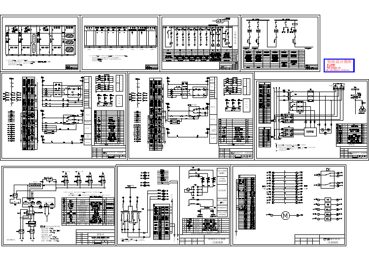
一套低压配电CAD图纸(标注详实)

石化厂一次、二次电气图
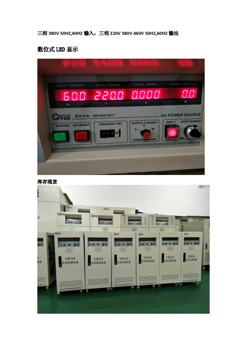
三相380V,50HZ,60HZ输入,三相220V,380V,460V ,50HZ,60HZ输出
频率波动范围 功率因数 交流输出 相数 波形 低档电压
50HZ or 60HZ±15% ﹥0.9
三相 SINE WAVE 单相电压 0-150V 连续可调,三相电压 0-260V
高档电压
连续可调 单相电压 0-300V 连续可调,三相电压 0-520V
频率
连续可调 60HZ,50HZ,40-499.9HZ 连续可调
数位式 LED 显示 4 位数,数位电压表,解析度 0.1V 4 位数,数位电流表,解析度 0.1A 4 位数,数位瓦特表 4 位数,数位频率表
高速变频风扇冷却,强制冷风 -10℃ to 50℃ 0~90%(非凝结状态) ≤1500m
频率稳定率 整机性能 电源稳压率 负载稳压率 波形失真度 效率 反应时间 波峰因子 保护装置
≤0.01%
﹤1% ﹤1% ﹤1% ﹥90% ≤2ms 3:1 具有过压,过流,超载,输入欠压,过高温,短路
显示 显示介面 电压 电流 功率 频率 环境及其它 冷却装置 功能,反应速度快,反应时间在 2ms 以内
具有过流,过压,过温,短路,过载等多重保护及报警功能
高精度的稳频稳压功能,快速调节电压,频率
主要元器件均采用原装进口品牌,品质可靠
三进三出变频电源技术参数
电路方式
IGBT/PWM 脉宽调制方式
交流输入 相数 波形 电压
三相 SINEWAWE
380V±15%
三相 380V 50HZ,60HZ 输入,三相 220V 380V 460V 50HZ,60HZ 输出
数位式 LED 显示
库存现货
输出电压:单相 0-300V 连续可调,三相 0-520V 连续可调(可特殊定制做至
1000V)
输出频率:60HZ,50HZ,40-499.9HZ 连续可调
ncp18xh103f03rb规格书

ncp18xh103f03rb规格书规格书:NCP18XH103F03RB1. 产品概述:\nNCP18XH103F03RB是一款高性能、高可靠性的电容器。
它采用了先进的材料和制造工艺,具有优异的电气性能和稳定性,适用于广泛的应用领域。
2. 产品特点:\n - 高容量:NCP18XH103F03RB具有较大的电容量,能够满足各种应用需求。
\n - 低ESR:该电容器具有低等效串联电阻(ESR),能够提供更好的功率传输和响应速度。
\n -高温稳定性:NCP18XH103F03RB在高温环境下仍能保持良好的性能,适用于苛刻的工作条件。
\n - 长寿命:该电容器采用了优质材料和可靠的制造工艺,具有长寿命和稳定性。
3. 产品规格:\n - 电容值:10,000pF\n - 额定电压:50V\n - 容差:±1%\n - 工作温度范围:-55℃至+125℃\n - 封装类型:Radial Leaded\n - 封装尺寸(长×宽×高):4.5mm × 3.2mm × 2.5mm\n - 重量:约0.1g4. 应用领域:\n NCP18XH103F03RB广泛应用于电子设备和电路中,包括但不限于:\n - 通信设备\n - 汽车电子\n - 工业自动化\n - 医疗设备\n - 能源管理系统5. 质量认证:\n NCP18XH103F03RB符合国际标准和质量要求,已通过ISO9001质量管理体系认证。
每个产品都经过严格的测试和质量控制,确保其性能和可靠性。
6. 包装与交货:\n NCP18XH103F03RB以卷装形式供应,每卷包含1000个电容器。
产品将在订单确认后的3个工作日内交付。
以上是对NCP18XH103F03RB规格书的简要介绍。
如需更详细的信息,请参考产品说明书或与我们联系。
我们将竭诚为您提供技术支持和解答您的疑问。
JP柜电气方案及元件配置cad详图纸(大全)
档案馆蓄热式电锅炉房全套设计施工图

电梯继电器控制电气CAD图

500KVA箱变系统图及基础

PMC-651M电动机保护测控装置使用说明书_V1.6_20100507

PMC-651M电动机保护测控装置操作使用说明书(V1.6版)深圳市中电电力技术有限公司2010年5月5日目录1装置简介 (1)1.1概述 (1)1.2产品特点 (1)1.3基本功能 (1)2技术指标 (2)2.1工作环境条件 (2)2.2额定参数 (2)2.3准确度 (2)2.4遥信分辨率 (3)2.5过载能力 (3)2.6继电器输出 (3)2.7开关量输入 (3)2.8电气绝缘性能 (4)2.9机械性能 (4)2.10电磁兼容性能 (4)3功能说明 (5)3.1保护功能 (5)3.1.1电动机运行状态识别 (5)3.1.2起动时间过长 (5)3.1.3瞬时电流速断 (5)3.1.4定时限过流 (6)3.1.5反时限过流 (6)3.1.6过负荷保护 (6)3.1.7过热保护 (6)3.1.8负序过流 (7)3.1.9堵转保护 (7)3.1.10负荷丢失 (7)3.1.11缺相保护 (8)3.1.12两段式零序过流 (8)3.1.13过电压保护 (8)3.1.14低电压保护 (8)3.1.15绝缘监视 (9)3.1.16TV断线 (9)3.1.17控制回路异常 (9)3.1.18TA断线 (9)3.2开入量配置 (10)3.3测量监视功能 (10)3.3.1测量数据 (10)3.3.2保护数据 (11)3.3.3计量数据 (11)3.3.4遥信功能 (11)3.3.5AI/AO (12)3.4控制功能 (12)3.5通讯功能 (12)3.6记录功能 (13)3.6.1事件记录 (13)3.6.2起动报告 (14)3.6.3故障录波记录 (14)3.7谐波分析功能 (14)3.8对时功能 (15)4操作使用说明 (15)4.1按键操作 (15)4.2信号指示灯 (15)4.3装置上电 (15)4.4默认显示 (16)4.5事件报告 (16)4.6显示说明 (16)4.6.1数据查询 (17)4.6.2定值查询 (17)4.6.3定值管理 (17)4.6.4报告管理 (19)4.6.5谐波分析 (22)4.6.6装置维护 (22)4.6.7装置调试 (22)4.6.8定值清单 (23)5安装调试说明 (28)5.1安装 (28)5.1.1装置安装图 (28)5.1.2背板端子布置 (29)5.2通电试验 (32)5.3投运前调试 (32)5.4装置故障分析 (32)6接线原理图 (34)6.1装置接线原理图 (34)6.2操作回路原理图 (36)7售后服务承诺 (38)7.1装置升级 (38)7.2质保范围 (38)8附录1:手册变更信息 (39)1装置简介1.1概述PMC-651M是深圳市中电电力技术有限公司精心开发适用于各种高压电动机的保护测控装置。
浦沅汽车吊机QY25H421产品介绍书

浦沅牌QY25H421汽车起重机 产品介绍书长沙中联重工科技发展股份有限公司QY25H421汽车起重机技 术 规 格 书QY25H421/271.产品特点QY25H421汽车起重机是我公司为适应市场需求,集我公司多年的经验和先进技术自主开发的新一代高性能产品。
起重机的起升高度、主臂长度、工作速度、起重能力等性能参数均处于先进水平。
该产品是一种全回转、伸缩动臂式、手动控制的汽车起重机。
采用本公司自制的全驾三桥专用底盘,视野宽广,装饰豪华舒适,6×4驱动。
采用了最新的三联齿轮泵系统,使得各执行机构的工作能力充分发挥,在液压系统中,设有溢流阀、平衡阀、液压锁、制动阀等安全装置,以防油路过载及避免由于油管破裂而引起的意外事故发生。
配备了力矩限制器等多种安全装置和齐全的照明系统,可保证操作安全可靠,并便于夜间作业。
2.整机规格2.1产品型号汽车行业型号: ZLJ5292JQZ25H工程行业型号: QY25H2.2 主要技术参数项 目数 值 备 注最大额定总起重量 kg 25000 基本臂最大起重力矩 kN.m 980 最长主臂最大起重力矩 kN.m 573 基本臂最大起升高度 m 10.9 主臂最大起升高度 m 33.8工作性能参数副臂最大起升高度 m 41.6不考虑吊臂变形单绳最大速度(主卷扬)m/min 115卷筒第三层 单绳最大速度(副卷扬)m/min 115卷筒第三层 起重臂起臂时间 s 50 起重臂伸出时间 s 80 工作 速度回转速度 r/min 0~2最高行驶速度 km/h 78 最大爬坡度 % 30 最小转弯直径 m 22 最小离地间隙 mm 220排气污染物排放值及烟度限值符合标准规定 GB3847-2005GB17691 -2005第二阶段行驶 参数百公里油耗 L 45 行驶状态自重(总质量) kg 29130 整车整备质量 kg 29000 前轴轴荷 kg 6500 质量 参数后桥轴荷 kg 22630 外形尺寸(长×宽×高) mm 13000×2500×3500支腿纵向距离 m 5.36跨距 支腿横向距离 m 6.1跨距 主臂长 m 10.5~33.3 主臂仰角 ° -2~80副臂长 m 8 尺寸 参数副臂安装角 ° 0 、 30 型号 ZLJ5322类别 二类型号WD615.56 额定功率 kW/r/min 193/2200 发 动 机 最大输出扭矩 N.m/r/min 1100/1300~1600 底盘生产企业 长沙中联重工科技发展股份有限公司浦沅分公司2.3额定起重量表单位:kg主 臂(m)主臂+副臂 39+8(m) 前方(打第五支腿)、侧、后方作业前方作业区(不打第五支腿)安装角0°安装角30°幅度 (m)10.50 14.90 19.50 24.10 28.7033.3010.5014.9019.5024.1028.7033.30主臂仰角(°)侧后 前方侧后 前方 3.0 2500017000 2500017000 3.5 2500017000 16000 250001700016000 4.0 2400017000 16000 240001700016000 80 3000 3000 1500 1500 4.5 2200017000 16000 11000 220001700016000 11000 78 3000 3000 1500 1500 5.0 2000017000 16000 10800 200001700016000 10800 76 3000 3000 1500 1500 5.5 1790017000 15200 105008000 174001700015200 105008000 74 2900 2900 1500 1500 6.0 1630016500 14200 102008000 136001410014200 102008000 72 2800 2800 1450 1450 6.5 1490015200 13200 9800 8000 7000 129001170012300 98008000700070 2650 2450 1400 1400 7.0 1330013700 12300 9300 8000 7000 9400 1000010500 93008000700068 2500 2050 1350 1350 8.0 1050011000 11000 8500 7400 6500 6700 74007900 79007400650066 2400 1750 1300 1300 9.0 85009000 9300 7800 6800 6000 5000 56006100 62006300600064 2300 1450 1270 1200 10.0 7500 7800 7200 6300 5500 45004900 50005100520062 2150 1250 1240 1050 11.0 6300 6600 6550 5800 5000 35003200 40004150425060 2050 1050 1210 850 12.0 5300 5600 5700 5400 4600 28002600 33003450355058 1850 900 1180 750 13.0 4800 4950 5000 4200 2100 27002850295056 1650 700 1150 600 14.0 4100 4300 4450 4000 1700 22002350245054 1500 600 1120 500 15.0 3600 3750 3900 3900 1400 18001950205052 1350 450 1100 350 16.0 3100 3300 3400 3500 15001650175050 1200 350 1070 250 18.0 2600 2700 2800 10001150125045 920 840 20.0 2000 2100 2200 600 750 850 40 700 660 22.0 1650 1700 1800 450 550 35 520 490 24.0 1300 1400 30 370 26.0 1000 1100 28.0 85032.4 行驶状态外形尺寸图(尺寸单位:mm)43.上车部分规格3.1主臂及伸缩机构四节箱型伸缩臂,六边形截面,截面抗弯性能优良。
软启动电气控制图纸(含主要元件表)

IC库存表

SOP SOP SOP SOP SOP SOP SOT SOP TSSOP SOP SOP SOP SOP SOP SOP-14 SOP SOP SOP SOP SOP SOP SOT23-5 SOT23-5 SC70-5 SOT-353 SOT-353 SOT-353 SOT-353 SOT23-5 SOT23-5 SOP SOP SOP TSSOP SOP SOP TSSOP SOT-363 SOT-353 SOP TSSOP SOP TSSOP SOT-353 SOT-153 SOT-23 TSSOP
NXP NXP NXP NXP NXP NXP NXP NXP NXP NXP NXP NXP NXP NXP NXP NXP NXP NXP NXP NXP NXP NXP NXP NXP NXP NXP NXP NXP NXP NXP NXP NXP NXP NXP NXP NXP NXP NXP NXP NXP NXP NXP NXP NXP NXP NXP NXP
NXP NXP NXP NXP NXP NXP NXP NXP NXP NXP NXP NXP NXP NXP NXP NXP NXP NXP NXP NXP NXP NXP NXP NXP NXP NXP NXP NXP NXP NXP NXP NXP NXP NXP NXP NXP NXP NXP NXP NXP NXP NXP NXP NXP NXP NXP NXP
11+ 11+ 11+ 11+ 11+ 11+ 11+ 11+ 11+ 11+ 11+ 11+ 11+ 11+ 11+ 11+ 11+ 11+ 11+ 11+ 11+ 11+ 11+ 11+ 11+ 11+ 11+ 11+ 11+ 11+ 11+ 11+ 11+ 11+ 11+ 11+ 11+ 11+ 11+ 11+ 11+ 11+ 11+ 11+ 11+ 11+ 11+
人民电器 JJW、JSW精密净化交流稳压器 产品说明书
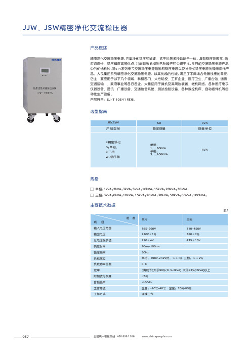
JJW 、JSW 精密净化交流稳压器产品概述精密净化交流稳压电源,它集净化稳压和滤波、抗干扰等多种功能于一体,具有稳压范围宽、响应速度快、稳压精度高等优点,并能有效地抑制各种噪声和尖峰干扰,是目前交流稳压电源产品中的优选机种,是614系列电子交流稳压电源磁饱和稳压电源以及补偿式稳压电源的理想换代产品。
人民集团系列精密净化交流稳压电源,以其优越的性能,满足了不同场合电器设施的需要,它主 要应用于以下几个领域:科研部门、大专院校、工矿企业、医疗卫生、广播台站、通讯、交通运输 、政府事业等各行各业,大量使用于微机及其周边装置、微机网络,各种医疗电子仪器设备、通讯 广播设备、交通信号系统、测试检验设备、各种数控机床、自动插件机等自动化生产设备。
产品符合: SJ /T 10541 标准。
选型指南□ 30kVA ;□ 三相:3kVA ;6kVA ;10kVA ;15kVA ;20kVA ;30kVA ;50kVA ;60kVA ;100kVA ;单相:1kVA ;2kVA ;3kVA ;5kVA ;10kVA ;15kVA ;20kVA ;规格表1主要技术数据037本稳压电源是以正弦能量分配器为核心,配以大容量滤波器和集成化控制电路而构成,主回路的工作原理大致如下图1和图2:净化电源电路原理图(此图仅供参考,如有修改,恕不另行通知)输入输出图1LNLNKC1BJL2L3L5C5C3L1FUSESCRZ C2R8IC3IC2C1R6R3VR1R1R2R5R7C3R11C9R15IC4+12V VINGNDR13C5C6C7C8B2L1C -1L3C -3R24B1L5C -2XOUTIN图2T1R10D1D2N9C4D7JXTST2T3R22R21WDR23R18D4D5T4图中K 为控制开关,控制着整个稳压电源的起停,C1-C3及L1-L3和可变阻抗“Z ”构成了有名的正弦能量分配电路。
L3或L2组成一自藕变压器T1,可变阻抗“Z ”由双向可控硅SCR 和电感L 组成,外加三次谐波滤波器L3、C3和五次谐波滤波器L5、C5。
gudel中国介绍
SYSTEMS
不锈钢齿轮 铜齿轮
SERVICE
钢制斜齿 轮
注射模共聚甲荃 塑料齿轮
铸铁螺旋 伞齿轮
螺旋伞齿轮
APPLICATIONS
蜗轮 蜗轮环 蜗杆轴 空心蜗杆轴
首页
COMPONENTS
MODULES
ROBOTICS
零部件MonoRoll
SYSTEMS
SERVICE
APPLICATIONS
高速应用MonoRoll
COMPONENTS
MODULES
ROBOTICS
SYSTEMS
SERVICE
APPLICATIONS
零部件应用:车床
Customer: Industrias Romi Application: Lathe Machine
COMPONENTS
MODULES
ROBOTICS
SYSTEMS
零部件应用:等离子切割机
Dual KRP+消隙方案
首页
COMPONENTS
MODULES
零部件
ROBOTICS
SYSTEMS
SERVICE
APPLICATIONS
小负载锥齿轮单元PV
中负载锥齿轮单元HKF
齿轮齿条系列
重负载锥齿轮单元FK
首页
COMPONENTS
MODULES
零部件
钢齿轮
共聚甲荃 塑料齿轮
铸锌齿轮
ROBOTICS
MODULES
ROBOTICS
SYSTEMS
零部件,行星齿轮减速器
SERVICE
APPLICATIONS
伺服行星齿轮减速器 GSP多样化的设计、全面的产品系列规格以及可选配置,使技术人员 可以得到最精确的解决方案。 大扭矩范围 从 250 Nm 到 6000Nm 5 种不同规格 8 种不同的减速比 两种精度水平 (1’ 或者 3’背隙) 每种规格都有直角电机安装方式
华为MateBook X Pro 笔记本电脑说明书
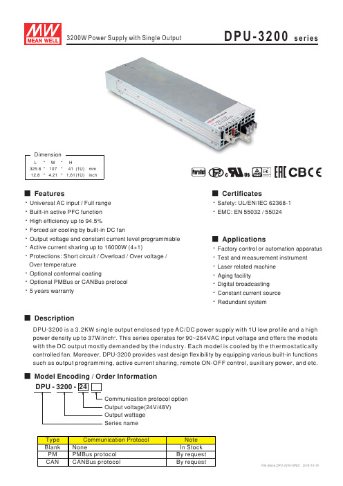
Protections: Short circuit / Overload / Over voltage /
DPU-3200series
Over temperature
Optional conformal coating
Optional PMBus or CANBus protocol 5 years warranty
■Features
■Applications
DPU-3200
series
Output wattage Output voltage(24V/48V)
Series name
Communication protocol option
DPU-3200series SPECIFICATION
DPU-3200series
File Name:DPU-3200-SPEC 2018-10-18
DPU-3200series
File Name:DPU-3200-SPEC 2018-10-18
■Model Encoding / Order Information
■Description
Universal AC input /Full range Built-in active PFC function High efficiency up to 94.5%
Forced air cooling by built-in DC fan
DPU-3200series
File Name:DPU-3200-SPEC 2018-10-18
S701X25N3BP软启动器与辅助联络器说明书
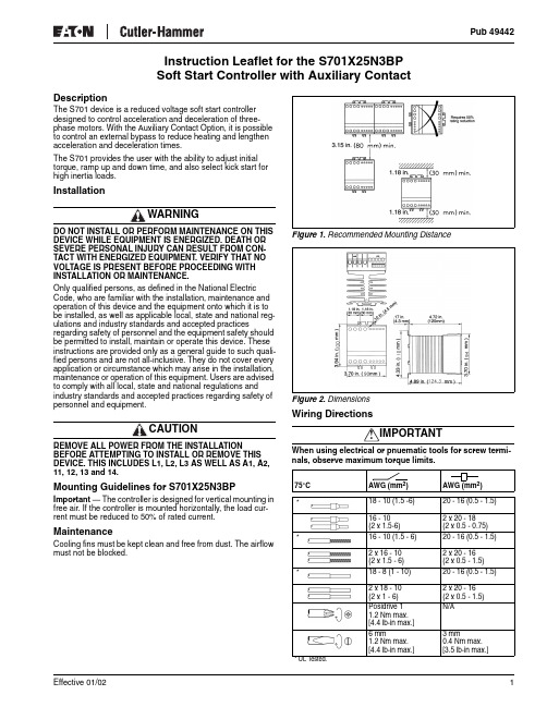
Instruction Leaflet for the S701X25N3BPSoft Start Controller with Auxiliary Contact DescriptionThe S701 device is a reduced voltage soft start controllerdesigned to control acceleration and deceleration of three-phase motors. With the Auxiliary Contact Option, it is possibleto control an external bypass to reduce heating and lengthenacceleration and deceleration times.The S701 provides the user with the ability to adjust initialtorque, ramp up and down time, and also select kick start forhigh inertia loads.InstallationWARNINGDO NOT INSTALL OR PERFORM MAINTENANCE ON THIS DEVICE WHILE EQUIPMENT IS ENERGIZED. DEATH OR SEVERE PERSONAL INJURY CAN RESULT FROM CON-TACT WITH ENERGIZED EQUIPMENT. VERIFY THAT NO VOLTAGE IS PRESENT BEFORE PROCEEDING WITH INSTALLATION OR MAINTENANCE.Only qualified persons, as defined in the National Electric Code, who are familiar with the installation, maintenance and operation of this device and the equipment onto which it is to be installed, as well as applicable local, state and national reg-ulations and industry standards and accepted practices regarding safety of personnel and the equipment safety should be permitted to install, maintain or operate this device. These instructions are provided only as a general guide to such quali-fied persons and are not all-inclusive. They do not cover every application or circumstance which may arise in the installation, maintenance or operation of this equipment. Users are advised to comply with all local, state and national regulations and industry standards and accepted practices regarding safety of personnel and equipment.CAUTIONREMOVE ALL POWER FROM THE INSTALLATION BEFORE ATTEMPTING TO INSTALL OR REMOVE THIS DEVICE. THIS INCLUDES L1, L2, L3 AS WELL AS A1, A2, 11, 12, 13 and 14.Mounting Guidelines for S701X25N3BP Important — The controller is designed for vertical mounting in free air. If the controller is mounted horizontally, the load cur-rent must be reduced to 50% of rated current. MaintenanceCooling fins must be kept clean and free from dust. The airflow must not be blocked.Figure 1. Recommended Mounting DistanceFigure 2. DimensionsWiring Directions!IMPORTANTWhen using electrical or pnuematic tools for screw termi-nals, observe maximum torque limits.75°C AWG (mm2)AWG(mm2)18 - 10 (1.5 -6)20 - 16 (0.5 - 1.5)16 - 10(2 x 1.5-6)2 x 20 - 18(2 x 0.5 - 0.75)16 - 10 (1.5 - 6)20 - 16 (0.5 - 1.5)2 x 16 - 10(2 x 1.5 - 6)2 x 20 - 16(2 x 0.5 - 1.5)18 - 8 (1 - 10)20 - 16 (0.5 - 1.5)2 x 18 - 10(2 x 1 - 6)2 x 20 - 16(2 x 0.5 - 1.5)Posidrive 11.2 Nm max.[4.4 lb-in max.]N/A6 mm1.2 Nm max.[4.4 lb-in max.]3 mm0.4 Nm max.[3.5 lb-in max.]* UL T ested.***Effective 01/021Effective 01/022Wiring DiagramsFigure 3. Wiring DiagramsUsing Line Voltage to Control S701When the contactor C1 is switched to the ON state, the motor controller will soft start the motor according to the set-tings of the ramp-up time and initial torque adjustments.When the contactor C1 isswitched to the OFF state, the motor will be switched off instantaneously.In this application, thecontactor will have no load during making operation.The contactor will carry and break the nominal motor cur-rent. Maximum voltage in this application is 300V AC.Separate Input Signal to S701When the control input is switched to the ON state (S closed), the motor control-ler will soft start the motor according to the settings of the ramp-up time and initial torque adjustments.When the control input is switched to the OFF state (S open), the motor will be switched off instantaneously only if the ramp-down time is adjusted to 0.With any other setting, the motor will be soft stopped according to the settings of the ramp-down time adjustment.Soft Reversing of Motors up to 5 hp/4 kWA soft reversing of a motor can easily be achieved by con-necting a reversing relay to the soft start controller.The reversing relay type S511 will determine the direction of rotation forward or reverse and the soft start type S701 will perform soft-starting and soft-stopping of the motor.If soft stop is not required, the application can be simplified by connecting the control cir-cuit of the soft start controllerto the main terminals asshown in Figure 6. A delay ofapproximately 0.5 secondsbetween forward and reversecontrol signal must be allowed to avoid influence from the volt-age generated by the motor during turnoff.Reversing of Motors Up to 15 hp/11 kWA soft-reversing of motors can easily be achieved when the motor load exceeds 5 hp/4 kW by connecting a mechanical reversing contactor to the soft start controller.The reversing contactor will determine the direction of rota-tion forward or reverse and the soft start controller type S701 will perform soft-starting and soft-stopping of the motor.If the contactors are always switched in no load conditions, the lifetime of the contactors will normally exceed 10 million cycles.Overload Protection with Manual Motor StarterOverload protection of the motor is easily achieved by installing a manual motor starter on the supply side of the motor.The manual motor starter pro-vides means for padlocking and the necessary clearance for use as a circuit isolator according to EN60204-1.Adjust the current limiter on the manual motor starteraccording to the rated nominal current of the motor.L1L2L3C1NOTE: Use thermal overload protection as required by the National Electric Code (NEC).AC-53b Application — with Bypass and START/STOPAC-53a Application — No Bypass and START/STOPS70124-300VL1 L2 L3T1 T2 T3A1 A2L1L2L3MC1Figure 4. Line Controlled Soft Start *S701Control Voltage 24 - 300 VL1 L2 L3T1 T2 T3A1 A2L1L2L3MSC1Figure 5. Input Controlled Soft Start *S511L1L2L3C1S701Figure 6. CombiningReversing ElectronicContactor and Soft StartController *L1L2L3FWDREVS701Figure 7. Combining Reversing Mechanical Contactor and Soft Start Controller *Figure 8. OverloadProtection with Manual Motor Starter** Use UL specified backup fuse.Effective 01/023Overload Protection with Mechanical StarterOverload protection of the motor is easily achieved by installing a mechanical starter on the supply side of the soft start controller.The overload provides the necessary motor protection for an overload condition.A short circuit protectivedevice is required to meet UL requirements.* Use UL specified backupfuse.SpecificationsTable 1. Thermal SpecificationsTable 2. Insulation SpecificationsCurrent DeratingCurrent Derating in High Temperature ApplicationsOperation in ambient temperatures exceeding 40°C is possible if the power dissipation is limited either by reducing the steady-state current or by reducing the duty cycle of the soft starter as shown in Table 3.Table 3. Temperature SpecificationsTable 4. Current Derating by Trip ClassEMCThis compartment meets the requirements of the product stan-dard EN60947-4-2 and is CE marked according to this standard.Table 5. Output Specifications — Main CircuitTable 6. Control SpecificationsProduct SelectionTable 7. Product Description and Item SelectionShort Circuit ProtectionTwo types of short circuit protection can be used:short circuit protection by circuit breaker short circuit protection by fusesShort circuit protection is divided into two levels — Type 1 and Type 2.Type 1 — protects the installationType 2 — protects the installation and the semiconductors inside the motor controllerShort Circuit Protection by Circuit BreakerA 3-phase motor with a correctly installed and adjusted over-load relay will not short-circuit totally to earth or between the 3 phases. Part of the winding will normally limit the short circuit current to a value that will cause instantaneous magnetic trip-ping of the circuit breaker without damage to the soft starter. The magnetic trip response current is approximately 11 times the maximum adjustable current.DescriptionSpecification Power dissipation for continuous operation PD max.2 W/APower dissipation for intermittent operation PD 2 W/A x duty cycle Cooling Method Natural convection Mounting (No Derating)Vertical ±30° Operating temperature range, EN60947-4-2 (no derating)-5° to 40°C* [23° to 104°F]* UL Tested.Storage temperature, EN60947-4-2-20° to 80°C [-4° to 176°F]Max. operating temperature with current derating according to table60°C [140°F]DescriptionSpecification Rated insulation voltage Ui 660 Volt Rated impulse withstand voltage Uimp 4 kVolt Installation categoryIIIAmbient Temperature S701X25N3BP 50°C [122°F]20A continuous Limited Duty Cycle Rating by 50°C On-time max. 15 min. Duty cycle max. 0.860°C [140°F]17A continuous Limited Duty Cycle Rating by 60°COn-time max. 15 min. Duty cycle max. 0.65Figure 9. Overload Protection with Mechanical Starter *Overload Trip ClassWithout BypassWith Bypass10A 10203025A 25A 20A 15A30A 30A 24A 19.5AApprovals: UL Std. No. 508Environment: Degree of Protection / Pollution Degree: IP20 / 3DescriptionSpecificationShort circuit protecting fuse (max.)80 A g L/g G. No time delay Operational current (max.)25A AC-53a, 30A AC-53b Semiconductor protecting fuse (max.)6300 A 2S Overload relay trip class10 or 10ADescriptionSpecificationControl voltage range24 – 300V AC/DC Control current/power (max.)15 mA/2 VARamp-Up time Adjustable from 0.5 to 20 sec.Ramp-Down time Adjustable from 0.5 to 20 sec.Initial torqueAdjustable from 0 to 85% of nominal torque with optional Kick StartOutput/Current voltage (max.)0.5A AC14, AC15,24 – 480V AC 50 – 60 HzFuse (max.)10 A g L/g G. l 2t max. 72 A 2SLine Voltage (V AC)Motor Size w/o Bypass Motor w/Bypass Control Voltage Range** 24 – 480V for CE only.Controller TypeDesignationhp / kW hp / kW AC/DC208 – 23010 / 7.510 / 7.524 – 300V S701C25N3BP 400 – 48015 / 1120 / 1524 – 300V S701E25N3BP 550 – 60020 / 1525 / 1824 – 300V S701G25N3BP© 2002 Eaton Corporation All Rights Reserved Printed in USA Effective 01/02Short Circuit Protection by FusesType 1S701X25N3BP — protection max. 80A g I/g L/g G 63A T Type 2S701X25N3BP — protection max. I 2t of the fuse 6300A 2S NOTE:S701X25N3BP — When protected by H class fuses,this device is rated for use on a circuit capable of delivering not more than 5000 rms symmetrical amperes, 600V maximum.How to Adjust Time and Torque, Figure 10The Soft Starter will read time and torque settings in the OFF state. Repeated starts may trip the motor protection relay. DO NOT set the rotary switches in between positions. This cor-rupts the time and torque adjustment. Use screwdriver 2 mm x 0.5 mm.Ramp-Up Time and Initial TorqueTable 8. Ramp-Up Time and Initial Torque (Standard Load)Kick Start/Break LooseIf it is not possible to reach a time sufficient for the application, it may be necessary to kick start the load.Table 9. Kick Start/Break Loose (High Inertia Loads)Ramp-Down TimeFollow Table 8 to set Ramp-Up and Initial Torque .Table 10. Ramp-Down Time, e.g. Pump LoadsFigure 10. Time and Torque AdjustmentPositionSetting/AdjustmentSet the Ramp-Up switch to maximum.Set the Ramp-Down switch to minimum.Set the Initial Torque switch to minimum.Apply control signal for a few seconds. If the load does not rotate immediately, increment the Initial Torque and try again. Repeat until the load starts to rotate immediately on startup.Adjust Ramp-Up time to the estimated start time (the scale is in seconds) and start the motor.Decrease the Ramp-Up time until mechanical surge is observed during start.Increase the time one step to eliminate the surge.PositionSetting/AdjustmentSet the Ramp-Up switch to maximum.Set the Ramp-Down switch to minimum.Set the Initial Torque switch to minimum kick start torque.Apply control signal for a few seconds. If the load stops right after the 200ms “kick ”, increment the Initial Torque and try again. Repeat until the load continues to rotate after the “kick ”.Adjust Ramp-Up time to the desired start time (the scale is in seconds) and start the motor.PositionSetting/AdjustmentSet the Ramp-Down switch to maximum.Switch off the control voltage and observe any mechanical surges on the load. If there are none, decrement Ramp-Down switch and try again. Repeat until mechanical surge on the load is observed.Increase the time one step to eliminate the surge.。
- 1、下载文档前请自行甄别文档内容的完整性,平台不提供额外的编辑、内容补充、找答案等附加服务。
- 2、"仅部分预览"的文档,不可在线预览部分如存在完整性等问题,可反馈申请退款(可完整预览的文档不适用该条件!)。
- 3、如文档侵犯您的权益,请联系客服反馈,我们会尽快为您处理(人工客服工作时间:9:00-18:30)。
浦沅牌QY65H-3汽车起重机产品介绍书QY65H-3/27长沙中联重工科技发展股份有限公司浦沅分公司浦沅牌ZLJ5450JQZ65H汽车起重机技 术 规 格 书QY65H-3/271.产品特点浦沅牌ZLJ5450JQZ65H汽车起重机是我公司为适应市场需求,集我公司多年的经验和先进技术自主开发的新一代高性能产品。
起重机的起升高度、主臂长度、工作速度、起重能力等性能参数均处于目前国际先进水平。
该产品是一种全回转、伸缩动臂式、手动比例控制的汽车起重机。
采用本公司自制的全驾四桥专用底盘,视野宽广,装饰豪华舒适,8X4驱动,液压动力转向,轻便灵活。
该产品采用了最新的带负载反馈的手动比例换向阀及三联齿轮泵系统,使得各执行机构的工作能力充分发挥,手动操纵杆操纵,能实现主副起升、变幅、回转、伸缩诸机构之间的组合动作,极大地提高了起重机的工作效率。
具有操作轻便、灵活,工作平稳可靠,无级调速等特点。
在液压系统中,设有溢流阀、平衡阀、液压锁、制动阀等安全装置,以防油路过载,避免由于油管破裂而引起的意外事故发生。
该产品配备了力矩限制器等多种安全装置和齐全的照明系统,可保证操作安全可靠,并便于夜间作业。
该产品在原有主配重的基础上,增加了副配重供用户选用,以满足用户个性化需求。
2. 整机规格2.1产品型号汽车行业型号: ZLJ5450JQZ65H工程行业型号: QY65H产品特征号: QY65H-32.2 主要技术参数项 目数 值 备 注最大额定总起重量 kg 65000 基本臂最大起重力矩 kN.m 2160 最长主臂最大起重力矩 kN.m 1024 基本臂最大起升高度 m 12 主臂最大起升高度 m 41工作性能参数副臂最大起升高度 m 56不考虑吊臂变形单绳最大速度(主卷扬)m/min 140卷筒第四层 单绳最大速度(副卷扬)m/min 120卷筒第二层 起重臂起臂时间 s 65 起重臂伸出时间 s 100 工作 速度回转速度 r/min 0~1.8最高行驶速度 km/h 71 最大爬坡度 % 30 最小转弯直径 m 23.7 最小离地间隙 mm 250排气污染物排放值及烟度限值符合标准规定GB3847-2005 GB17691-2005第二阶段行驶 参数百公里油耗 L 55 行驶状态自重(总质量) kg 45000 整车整备质量 kg 44800 前轴轴荷 kg 19000 质量 参数后桥轴荷 kg 26000 外形尺寸(长×宽×高) mm 13890×2750×3650支腿纵向距离 m 5.95 支腿横向距离 m 7.00 主臂长 m 11.2~41.5 主臂仰角 ° -2~80 副臂长 m 9、15 尺寸 参数副臂安装角 ° 5 、 30型号 ZLJ5450特征号:ZLJ5450-1类别 二类型号WD615.46 额定功率 kW/r/min 266/2200 发 动 机 最大输出扭矩 N.m/r/min 1460/1400~1600 底盘生产企业 长沙中联重工科技发展股份有限公司浦沅分公司2.3 额定起重量表表1 不带活动配重,先伸油缸Ⅰ,且伸到位时的起重量表单位kg主臂(不带活动配重,先伸油缸Ⅰ,且伸到位)支腿全伸,侧方、后方作业工作 幅度 (m) 11.2m 15.0m 18.77m 26.35m 33.92m 41.5m 3 65000 3.5 61500 4 54000 46000 36000 4.5 48000 43000 35500 5 46500 40000 34000 21500 5.5 40000 35000 32000 21500 6 38000 33000 30000 21500 6.5 31000 28000 28500 21500 7 28000 26000 27000 21000 16500 8 22000 20000 21000 19000 15500 9 16000 15500 15500 17000 14500 9000 10 12000 13000 13500 13000 8800 11 10800 10000 11500 11500 8300 12 9000 8500 9000 9500 8000 13 6500 7800 9000 7500 14 5000 6500 8000 7300 15 5500 6500 6500 16 4500 6200 6000 18 3200 4800 5000 20 2000 3000 4000 22 1500 2400 2800 24 1800 2000 26 1500 28 1000最小吊臂角度 25° 35° 42°单位kg主臂(不带活动配重,先伸油缸Ⅱ,且伸到位)支腿全伸,侧方、后方作业工作 幅度 (m) 11.2m 18.77m 26.35m 33.92m 41.5m 3 65000 3.5 61500 4 54000 4.5 48000 5 46500 22000 5.5 40000 22000 6 38000 22000 6.5 31000 21000 7 28000 20000 16500 8 22000 19000 15500 9 16000 15500 14500 9000 9000 10 13000 13000 8800 8800 11 11500 11500 8300 8300 12 8800 10000 8000 8000 13 7000 8500 7500 7500 14 6200 7500 7300 7300 15 6500 6500 6500 16 5500 6200 6000 18 4600 4900 5000 20 3300 3900 4000 22 3000 2800 24 2500 2000 26 1500 28 1000最小吊臂角度 25° 35° 42°单位kg主臂(不带活动配重,先伸油缸Ⅰ,但没伸到位)支腿全伸,侧方、后方作业工作 幅度 (m) 11.2m 15.0m 18.77m 26.35m 33.92m 41.5m 3 65000 3.5 61500 4 54000 4.5 48000 5 46500 23000 22000 5.5 40000 23000 22000 6 38000 22000 22000 6.5 31000 21000 21000 7 28000 20000 20000 16500 8 22000 16800 19000 15500 9 16000 15200 15000 14500 9000 9000 10 12000 12000 12500 8800 8800 11 10800 10000 10000 8300 8300 12 9000 8000 9000 8000 8000 13 6500 7800 7500 7500 14 5000 6500 7300 7300 15 5500 6500 6500 16 4500 6200 6000 18 3200 4800 5000 20 2000 3000 4000 22 1500 2400 2800 24 1800 2000 26 1200 1500 28 1000 最小吊臂角度 25° 35° 42°单位kg主臂(带活动配重,先伸油缸Ⅰ,且伸到位)支腿全伸,侧方、后方作业 工作 幅度 (m) 11.2m 15.0m 18.77m 26.35m 33.92m 41.5m 3 65000 3.5 61500 4 54000 46000 36000 4.5 48000 43000 35500 5 46500 40000 34000 21500 5.5 40000 35000 32000 21500 6 38000 33000 30000 21500 6.5 33500 28000 28500 21500 7 29000 26000 27000 21000 16500 8 23500 21000 23000 19000 15500 9 17500 17000 17000 17000 14500 9000 10 12800 13500 15000 13000 8800 11 11000 11500 13000 12000 8300 12 9000 10000 11500 8000 13 7200 8500 10500 7500 14 5800 7500 9200 7300 15 6500 7500 6500 16 5500 6500 6400 18 4500 5000 5300 20 3200 3800 4500 22 2500 2900 3500 24 2200 2500 26 1800 281200 最小吊臂角度 25° 35° 42°单位kg主臂(带活动配重,先伸油缸Ⅱ,且伸到位)支腿全伸,侧方、后方作业工作 幅度 (m) 11.2m 18.77m 26.35m 33.92m 41.5m 3 65000 3.5 61500 4 54000 4.5 48000 5 46500 22000 5.5 40000 22000 6 38000 22000 6.5 33500 21000 7 29000 21000 16500 8 23500 19000 15500 9 17500 15500 14500 9000 9000 10 13000 13000 8800 8800 11 11500 11500 8300 8300 12 8800 10000 8000 8000 13 7500 8500 7500 7500 14 6500 8000 7300 7300 15 7000 6800 6500 16 6800 6600 6400 18 5000 5200 5300 20 4000 4000 4500 22 3500 3500 24 3200 2500 26 1800 281200 最小吊臂角度 25° 35° 42°单位kg主臂(带活动配重,先伸油缸Ⅱ,且伸到位)支腿全伸,侧方、后方作业工作 幅度 (m) 11.2m 18.77m 26.35m 33.92m 41.5m 3 65000 3.5 61500 4 54000 4.5 48000 5 46500 22000 5.5 40000 22000 6 38000 22000 6.5 31000 21000 7 28000 20000 16500 8 22000 19000 15500 9 16000 15000 14500 9000 9000 10 12000 13000 8800 8800 11 11500 11500 8300 8300 12 9000 9000 8000 8000 13 7200 7800 7500 7500 14 5800 7000 7300 7300 15 6500 6500 6500 16 5500 6200 6400 18 4500 5000 5300 20 3200 3800 4500 22 2500 2900 3500 24 2200 2500 26 1800 281200 最小吊臂角度 25° 35° 42°表7主臂全伸加副臂时的起重量表单位kg主臂+副臂支腿全伸,侧方、后方作业 41.5m+9m 41.5m+15m 主臂 仰角 副臂安装角 副臂安装角 5° 30° 5° 30° 80° 4000 2150 2400 1000 78° 3800 2050 2180 1000 76° 3500 1950 1920 1000 74° 3150 1900 1820 1000 72° 2850 1850 1690 1000 70° 2700 1800 1530 1000 68° 2550 1750 1380 900 66° 2450 1650 1230 800 64° 2150 1400 1080 700 62° 1850 1150 950 600 60° 1550 1000 830 58° 1350 850 700 56° 1100 700 600 54° 950 550 500 52° 750 50°2.4 行驶状态外形尺寸图(尺寸单位:mm)103上车主要零部件规格3.1主臂及伸缩机构五节箱型伸缩臂,六边形截面,截面抗弯性能优良。
