TRV-240中文资料
TRV-xxx中文资料
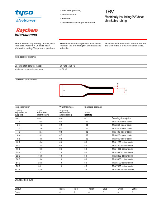
Temperature ratingOrdering informationStandard coloursOperating temperature range:-30°C to +105°C Minimum recovery temperature:+150°CInside diameter Wall thickness Standard package D (min)Expanded as supplied d (max)Recovered after heating W (nom)Recovered after heating Spool quantity mm mm mm m Ordering description 1.60.80.4100TRV-160-colour code 2.4 1.20.5100TRV-240-colour code 3.2 1.60.5100TRV-320-colour code 4.8 2.40.5100TRV-480-colour code 6.4 3.20.5100TRV-620-colour code 9.5 4.50.6100TRV-950-colour code 12.7 6.40.850TRV-1270-colour code 15.07.50.850TRV-1500-colour code 19.09.50.850TRV-1900-colour code 25.412.7 1.050TRV-2540-colour code 32.016.0 1.050TRV-3200-colour code 38.019.0 1.050TRV-3800-colour code 51.025.5 1.050TRV-5100-colour code 76.038.1 1.025TRV-7625-colour code 102.051.01.325TRV-10200-colour codeColour Black Red Yellow Blue Green White Code24569•Self extinguishing •Non-irradiated •Flexible•Good mechanical performanceTRVElectrically insulating PVC heat-shrinkable tubingTRV is a self extinguishing, flexible, non-irradiated, Poly Vinyl Chloride heat-shrinkable tubing. The product provides excellent mechanical performance and is resistant to a wide range of chemicals and solvents.TRV finds extensive use in the Automotive and Commercial Electronics industries.Raychem Interconnect Cheney Manor Industrial Estate Swindon, Wiltshire SN2 2QE Tel:(44)-1793-528171 Fax:(44)-1793-616652All of the above information, including illustrations, is believed to be reliable. Users, however, should independently evaluate the suitability of each product for their application. Tyco Electronics makes no warranties as to the accuracy or completeness of the information and disclaims any liability regarding its use. Tyco Electronics only obligations are those in the Standard Terms and Conditions of Sale for this product and in no case will Tyco Electronics be liable for any incidental, indirect or consequential damages arising from the sale, resale, use or misuse of the product. Tyco Electronics Specifications are subject to change without notice. In addition Tyco Electronics reserves the right to make changes in materials or processing, without notification to the Buyer, which do not affect compliance with any applicable specification.TRVRI0037.1299 Raychem and TRV are trademarks of Raychem Interconnect, a division of Tyco Electronics Corporation.PerformanceSpecifications Heat ageing:168 h at 136°C UL 224 Corrosion resistance:No corrosion ASTM D2671 Dielectric strength:15 MV/m min IEC 243Fluid resistance 24h at 23°C, ISO 37:Tensile strength 12 MPa (min)Elongation 150% (min)Test Fluids:IRM 902Lubricating oil 0-149Anti-icing fluidFlammability:Pass UL 224 VW1For full product performance details consult Raychem Specification RK 6147/1. Raychem Specification RK 6147/1.。
DDR-240系列产品说明书

■ Applications
Bus,tram,metro or railway system Industrial control system Semi-conductor fabrication equipment Factory automation Electro-mechanical Wireless network Telecom or datacom system
EN50155:2017-Comply with S1 level
OVERLOAD
Normally works within 150% rated output power for more than 3 seconds and then constant current protection 105~135% Note.5 rated output power with auto-recovery
MTBF
484.9K hrs min. Telcordia SR-332 (Bellcore) ; 189.9K hrs min. IL-HDBK-217F (25℃)
OTHERS DIMENSION
40*125.2*113.5mm (W*H*D)
OPERATING ALTITUDE Note.7 2000 meters
SAFETY STANDARDS
IEC 62368-1 (LVD, except for 67.2~154Vin), EAC TP TC 004, AS/NZS 62368.1 approved; Design refer to UL508
WITHSTAND VOLTAGE
I/P-O/P:4KVdc I/P-FG:2.5KVdc O/P-FG:0.71KVdc
TRD-12_15系列 船用雷达用户使用说明书_中文_

目 录第一章概述 (5)1.1概述 (5)1.2雷达系统介绍 (5)1.3天线收发单元 (7)1.4雷达显示单元 (8)1.4.1雷达显示屏幕介绍 (8)1.4.2雷达显示器背面接口介绍 (10)1.5其他附件 (11)1.5.1雷达电缆线 (11)1.5.2电源线 (12)第二章多媒体雷达安装 (13)2.1天线收发单元安装 (13)2.1.1天线收发单元安装注意事项 (13)2.1.2横杆天线收发单元安装步骤 (14)2.1.3圆盘天线安装步骤 (16)2.2显示单元安装 (17)2.2.1显示器单元安装注意事项 (17)2.2.2显示器单元安装步骤 (17)2.3配线 (19)2.3.1布线要求 (19)2.3.2收发机接线 (19)2.3.3电源线接线 (19)2.4调试和验收 (20)2.4.1开机 (20)2.4.2按键检查 (20)2.4.3方位调整 (20)2.4.4距离调整 (20)2.4.5系统验收 (20)第三章基本操作 (22)3.1开机/关机步骤 (22)3.1.1显示器开机/关机 (22)3.1.2收发机待机/发射 (23)3.2量程选择 (24)3.3增益/海浪抑制/雨雪抑制/调谐调整 (25)3.3.1增益调整 (25)3.3.2海浪抑制调节 (26)3.3.3调谐 (26)3.3.4噪声抑制调节 (27)3.3.5雨雪抑制调节 (27)3.4目标回波显示效果调整 (27)3.4.1同频干扰抑制 (27)3.4.2回波扩展 (28)3.4.3尾迹功能 (28)3.5测量本船到目标之间的距离和方位 (28)3.5.1光标测量 (28)3.5.2 VRM/EBL移动圈/方位线测量 (28)3.5.3设置第一条VRM/EBL (29)3.5.4浮动方位线 (29)3.6警戒圈设置 (30)3.6.1第一警戒圈设置 (30)3.6.2第二警戒圈设置 (31)3.6.3警戒圈报警强度 (31)3.7调整显示模式 (31)3.7.1参照方位线 (31)3.7.2雷达模式和方位 (32)3.7.3距标圈开启/关闭 (33)3.7.4船首线消隐 (33)3.8零距离/方位调整 (33)3.9主瓣抑制 (34)3.10自动调谐预设 (34)3.11增益预设 (35)3.12发射脉宽调整 (35)第四章显示界面设置 (37)4.1显示模式设置 (37)4.2调整屏幕显示亮度 (38)4.3按键声开关 (38)4.4模拟操作功能 (38)4.5数据条开关 (39)第五章菜单设置 (40)5.1雷达参数设置 (40)5.2系统参数设置 (41)5.3收发机状态 (43)5.4GPS状态 (45)5.5罗经/记程仪状态 (46)5.6显示器设置 (46)5.7数据条设置 (46)5.8系统信息 (46)5.9移出CF卡 (47)第六章M A R P A操作 (48)6.1MARPA图形符号解释 (48)6.2手动捕获目标 (50)6.3查看和删除跟踪目标 (51)6.4设置目标跟踪选项 (52)第七章A I S操作 (54)7.1AIS接收设备与雷达显示器的连接 (54)7.2设置雷达显示与AIS接收设备通信的波特率 (54)7.3AIS参数设置 (55)7.3.1 AIS接收信息开关 (56)7.3.2 AIS-GPS导航功能 (56)7.3.3警戒区识别及报警处理 (56)7.4AIS目标显示和处理 (57)7.5AIS船舶信息查询 (58)7.5.1 AIS船舶即时查询 (58)7.5.2 AIS船舶信息菜单查询 (58)附录A 常见问题和处理办法 (59)附录B 雷达背板接口和引脚定义 (61)附录C 红外遥控键盘 (66)附录D 缩语表............................................................................. . . (67)附录E 菜单功能层次图 (68)附录F 注意事项 (78)附录G 雷达显示器尺寸图 (79)附录H 横杆天线收发单元尺寸图 (80)附录I 圆盘天线尺寸图 (81)附录J 外接磁罗经转换器的连接和设置操作 (82)第一章概述非常感谢您购买太洋TRD-12/15系列彩色多媒体数字导航雷达,我们确信您会得到最高性能的产品和最优良的服务。
VDRP-240-48中文资料
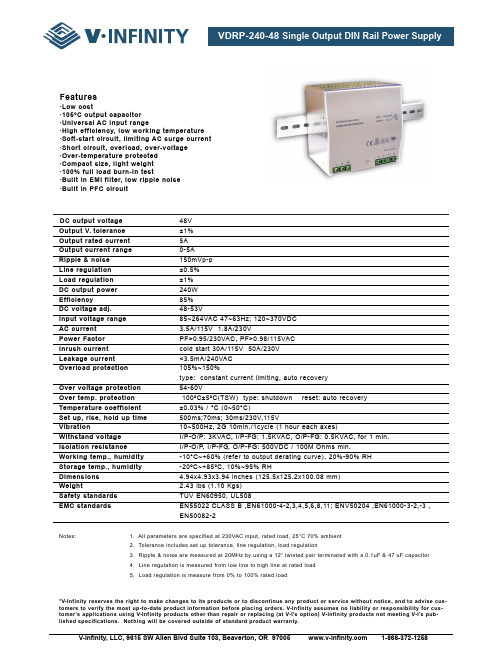
DC output voltage48V Output V.tolerance±1%Output rated current5A Output current range0-5A Ripple & noise150mVp-p Line regulation±0.5%Load regulation±1% DC output power240W Efficiency85% DC voltage adj.48-53V Input voltage range85~264VAC 47~63Hz; 120~370VDC AC current3.5A/115V 1.8A/230V Power FactorPF>0.95/230VAC, PF>0.98/115VAC Inrush currentcold start 30A/115V 50A/230V Leakage current<3.5mA/240VAC Overload protection105%~150%type: constant current limiting, auto recovery Over voltage protection54-60V Over temp. protection100ºC±5ºC(TSW) type: shutdown reset: auto recovery Temperature coefficient±0.03% / °C (0~50°C)Set up, rise, hold up time500ms;70ms; 30ms/230V,115V Vibration10~500Hz, 2G 10min./1cycle (1 hour each axes)Withstand voltageI/P-O/P: 3KVAC, I/P-FG: 1.5KVAC, O/P-FG: 0.5KVAC, for 1 min.Isolation resistanceI/P-O/P, I/P-FG, O/P-FG: 500VDC / 100M Ohms min.Working temp., humidity-10°C~+60% (refer to output derating curve), 20%-90% RH Storage temp., humidity-20ºC~+85ºC, 10%~95% RH Dimensions4.94x4.93x3.94 inches (125.5x125.2x100.08 mm) Weight2.43 lbs (1.10 Kgs) Safety standardsTUV EN60950, UL508EMC standards EN55022 CLASS B ,EN61000-4-2,3,4,5,6,8,11; ENV50204 ,EN61000-3-2,-3 ,EN50082-2Notes: 1. All parameters are specified at 230VAC input, rated load, 25°C 70% ambient2. Tolerance includes set up tolerance, line regulation, load regulation3. Ripple & noise are measured at 20MHz by using a 12” twisted pair terminated with a 0.1uF & 47 uF capacitor4. Line regulation is measured from low line to high line at rated load5, Load regulation is measure from 0% to 100% rated load*V-Infinity reserves the right to make changes to its products or to discontinue any product or service without notice, and to advise cus-tomers to verify the most up-to-date product information before placing orders. V-Infinity assumes no liability or responsibility for cus-tomer’s applications using V-Infinity products other than repair or replacing (at V-I’s option) V-Infinity products not meeting V-I’s pub-lished specifications. Nothing will be covered outside of standard product warranty.Features·Low cost·105°C output capacitor·Universal AC input range·High efficiency, low working temperature·Soft-start circuit, limiting AC surge current·Short circuit, overload, over-voltage·Over-temperature protected·Compact size, light weight·100% full load burn-in test·Built in EMI filter, low ripple noise·Built in PFC circuitDimensions (mm)。
环希工业 240说明书(1)

端子说明:
运行指示 单元指示 数据指示
操作按钮
1# L 2# N 3#TC 4#TA 5#TB 6#GND 7#V4 8#GND 9#V3 10#GND 11#V2 12#GND 13#V1
电电源源220VAC±20%50Hz 输出继电器常开 输出继电器公共端 输出继电器常闭 信号地 单元4输出端[0-10V] 信号地 单元3输出端[0-10V] 信号地 单元2输出端[0-10V] 信号地 单元1输出端[0-10V]
N 1 1A 250V 50Hz
注:电位器建议使用2K-10K
P6-2 江阴市环希工业控制设备有限公司
以上灰色区域为
! 可接强电区,本 机其他端子严禁
接触强电.
参数表
参数号 F01 F02 F03 F04 F05 F06 F07 F08 F09 F10 F11 F12 F13 F14 F15 F16 F17 F18 F19 F20 F21 F22 F23 F24 F25 F26 F27 F28 F29 F30 F31 F32 F33
14#GF1 15#GF2 16#GND 17#+10V 18#GF3 19#GF4 20#GND 21#+10V 22#G1 23#GND 24#UP 25#DOWN 26#RS
反馈1 反馈2 信号地 +10V参考电压,≤50mA 反馈3 反馈4 信号地 同17# 外部主给定1 信号地 上升端子 下降端子 启停端子
0:解锁 ቤተ መጻሕፍቲ ባይዱ:锁定 给定从0升到10V所需时间
范围0-100秒 范围0-13*
! 按ENT则参数恢复出厂值**
范围0.00-10.00
端子26闭合时:0:无动作1:G0=F22 0.01:最慢 4.00:最快
芯片产品说明书:74LVC240A 八极缓冲器 线路驱动器

DescriptionThe 74LVC240A provides two 4-bit buffers/drivers with separate output-enable (OE) inputs. When OE is low, the device passes data from the A inputs to the Y outputs. When OE is high, the outputs are in the high-impedance state.The device is designed for operation with a powersupply range of 1.65V to 3.6V.The inputs are tolerant to 5.5V allowing this device to be used in a mixed voltage environment. The device is fully specified for partial power down applications using I OFF . The I OFF circuitry disables the output preventing damaging current backflow when the device is powered down.Features∙ Supply Voltage Range from 1.65V to 3.6V ∙ Sinks or Sources 24 ma at V CC = 3V ∙ CMOS Low Power Consumption∙ I OFF Supports Partial -Power Down Operation∙ Inputs or Outputs Accept up to 5.5V∙ Inputs Can Be Driven by 3.3V or 5V Allowing for Mixed Voltage Applications∙ Schmitt Trigger Action at All Inputs∙ Typical V OLP (Quiet Output Ground Bounce) Less than 0.8V with V CC = 3.3V and T A = +25°C∙ Typical V OHV (Quiet Output dynamic VOH) Greater than 2.0V with V CC = 3.3V and T A = +25°C∙ESD Protection Tested per JESD 22▪ Exceeds 200-V Machine Model (A115)▪ Exceeds 2000-V Human Body Model (A114) ▪ Exceeds 1000-V Charged Device Model (C101) ∙ Latch-Up Exceeds 250mA per JESD 78, Class I ∙All devices are:▪ Totally Lead-Free & Fully RoHS compliant (Notes 1 & 2) ▪ Halogen and Antimony Free.“Green” Device (Note 3)Pin Assignments(Top View )TSSOP-20Top Transparent View 3245678913141217181615191120110V c c2OE 1Y22A42A31Y32A21Y42A 11Y1G N D1O E1A22Y42Y31A32Y21A42Y11A1QFN-20()terminal 1 index areaApplications∙ General Purpose Logic ∙ Bus Driving∙ Power Down Signal Isolation ∙Wide Array of Products Such as:▪ PCs, Notebooks, Netbooks, Ultrabooks▪ Networking Computer Peripherals, Hard Drives, CD/DVDROM▪ TV, DVD, DVR, Set Top BoxNotes: 1. No purposely added lead. Fully EU Directive 2002/95/EC (RoHS) & 2011/65/EU (RoHS 2) compliant.2. See /quality/lead_free.html for more information about Diodes Incorporated’s definitions of Halogen a nd Antimony free, "Green" and Lead-Free.3. Halogen and Antimony free "Green” products are defined as those which contain <900ppm bromine, <900ppm chlorine (<1500ppm total Br + Cl) and <1000ppm antimony compounds.Ordering InformationBuffer/Line Driver with 3 State OutputsQ20 : QFN-20Notes: 4. Pad layout as shown on Diodes Inc. suggested pad layout document AP02001, which can be found on our website at/datasheets/ap02001.pdf.5. V-QFN4525-20 is a JEDEC recognized naming convention that specifies the package thickness category as V and the number 4525 describes the package as 4.5mm X 2.5mm.Pin DescriptionsLogic DiagramFunction TableAbsolute Maximum Ratings(Notes 6 & 7)Notes: 6. Stresses beyond the absolute maximum may result in immediate failure or reduced reliability. These are stress values and device operation should be within recommend values.7. Forcing the maximum allowed voltage could cause a condition exceeding the maximum current or conversely forcing the maximum current couldcause a condition exceeding the maximum voltage. The ratings of both current and voltage must be maintained within the controlled range. Recommended Operating Conditions(Note 8)Note: 8. Unused inputs should be held at V CC or Ground.Operating CharacteristicsPackage CharacteristicsNote: 9. Test conditions for TSSOP-20 and V-QFN4525-20: Devices mounted on 4 layer FR-4 substrate PC board, 2oz copper, with minimum recommended pad layout per JESD 51-7.Parameter Measurement InformationFrom Output Under TestV l0 VOutput Control/2Output Waveform 1S1 at V LOAD (see Note B) Output Waveform 2 S1 at GND (see Note B)Voltage Waveform Enable and Disable TimesLow and High Level EnablingVoltage Waveform Pulse DurationV l0 V V OHV OLV OHV OLVoltage Waveform Propagation Delay TimesInverting and Non Inverting OutputsNotes:A. Includes test lead and test apparatus capacitance.B. All pulses are supplied at pulse repetition rate ≤ 10 MHz.C. Inputs are measured separately one transition per measurement.D. t PLZ and t PHZ are the same as t dis.E. t PZL and t PZH are the same as t EN0F. t PLH and t PHL are the same as t PD.Figure 1 Load Circuit and Voltage WaveformsMarking Information (1) TSSOP20(2) QFN-20 (V-QFN4525-20)Package Outline Dimensions (All Dimensions in mm)Please see /package-outlines.html for the latest version.(1) TSSOP-20(2) QFN-20 (V-QFN4525-20)Suggested Pad LayoutPlease see /package-outlines.html for the latest version.(1) TSSOP-20(2) QFN-20 (V-QFN4525-20)X1。
SA240资料

Website: www. E-mail: bill@
元器件交易网
SSA210/20/30/40/4x
ABSOLUTE MAXIMUM RATINGS (TA = 25 C)
O
PARAMETER Power Dissipation Forward Current Peak Forward Current Reverse Voltage Operating Voltage Storage Temperatire
Pb
SA210/20/30/40/4X 5mm LED Assembly Single Way to 4 Way
MECHANICAL DATA
5.2 4.7
4.85
6.35
0.5
6.35 3.17
25.9 6.35
6.35
8 3.17 6
30.84 8
8
1.2 + 5 9 2.54 1 2.54 SSA220X + 1 2 3 4
PARAMETER & CONDITIONS Viewing Angle Degrees Forward Voltage [If = 10mA] Reverse Current [Vr = 3V] Peak Wavelength [If = 10mA] Luminous Intensity [If = 10mA] 650nm Min = 2.2mcd RED [47VR] 40 Typ = 2.0V GREEN [47MG] YELLOW [47YY] 40 Typ = 2.1V Max = 10mA 563nm Min = 3.6mcd 585nm Min = 2.2mcd 40 Typ = 2.1V
+ 3.5 2.54 1 2 3 SSA240/4X 4
Lincoln Electric 240V 150A MIG FLUX 熔炼机说明书

Issued March2019•Index No. DC/12.58Advanced Auto-Set™includes five different wire/gas combinations and three wire size capabilities.•Wire/gas combinations include Flux Cored,Mild Steel with 100% CO2, Mild Steel with C25,Stainless Steel, and Aluminum with spool gun•Select the wire type and gas being used•Set the wire diameter (.024, .030 or .035 in.).A blue LED indicates that Auto-Set is activated•Dial in the thickness of what you’re welding•Start welding with the exact parametersyou need!Inverter technology combines best-in-class arccharacteristics with the portability of a 38-poundmachine. The arc is extremely forgiving tovariations in arc length and travel speeds.Multi-voltage plug (MVP™)allows connection tocommon 120- and 240-volt power receptacleswithout the use of anytools—simply choose the plug that fits thereceptacle and connect to the power cord.Angled cast-aluminum drive system withcalibrated tension knob creates consistentfeeding and easy setup.Quick Select™drive roll makes setup quickerby offering three grooves—two for differentsize solid wire and a third for flux-cored wire.Auto Spool Gun Detect™automatically detectswhen a MIG gun or spool gun is connected,eliminating the need for a switch.Fan-On-Demand™cooling system only operateswhen needed, reducing noise, energy use andcontaminants pulled though the machine.Smooth-Start™provides a smooth, spatter-freestart. It’s the best-starting machine in the smallMIG machine category.Thermal overload protection shuts down unitand activates the over temperature light ifairflow is blocked or duty cycle is exceeded.Automatically resets when unit cools.and can be set up to weld with .024–.035 inch(0.6–0.9 mm) solid wire and .030–.045 inch(0.8–1.2 mm) flux-cored wire. Millermatic®211Comes complete with:Power source10 ft. (3 m) MDX™-100 MIG gun10 ft. (3 m) work cable with clamp6.5 ft. (2m) power cord with MVP™plugsfor 120 V and 240 VFlow gauge regulator and gas hose forargon or AR/CO2mixHobart®spool of .030 in. (0.8 mm)solid wireTwo contact tips for .030 in. (0.8 mm) wireQuick Select™drive rolls for .024 in.(0.6 mm) or .030/.035 in. (0.8/0.9 mm)solid wire, and .030/.035 in.(0.8/0.9 mm) flux-cored wireMaterial thickness gauge229895Hook-and-loop cord wrapsNote: Shielding gas andsafety equipment not included.MIG Power Source,Wire Feeder and Gun PackageMiller Electric Mfg. LLCAn ITW Welding Company1635 West Spencer StreetP.O. Box 1079Appleton, WI 54912-1079 USAEquipment Sales US and CanadaPhone: 866-931-9730FAX: 800-637-2315International Phone: 920-735-4554International FAX: 920-735-4125Now with™MDX consumable system featuring a dual-locked,front-loading liner that optimizes wire feedability.Welder is warranted for three years, parts and labor.Gun warranted for 90 days, parts only.Uses 120- or 240-volt power PortableWEIGHSONLY38lb.Quick and easy setupMATER I AL T H I C KNESS789121110AmpsV o l t s% Duty CycleW e l d A m p e r e s250200150********5040302060708090100Duty Cycle Chart240 V120 V, 20 APerformance Data2Control PanelOperation ModesCertified by Canadian Standards Association to both the Canadian and U.S. Standards.Rated Output 115 A at 19.8 VDC,20% duty cycle 150 A at 21.5 VDC,40% duty cycleMax. Open-CircuitVoltage 54Amps Input at Rated Output, 50/60 Hz 120 V 240 V KVA KW 24.3 – 2.9 2.9– 16.6 4.0 4.0Wire Feed Speed60–600 ipm (1.5–15.2 m/min.)Wire Type and DiameterSolid/stainless: .024–.035 in.(0.6–0.9 mm)Flux-cored: .030–.045 in. (0.8–1.2 mm)Dimensions H: 12.5 in. (318 mm)W:11.25 in. (286 mm)D: 20.5 in. (521 mm)Net Weight 38 lb.(17.2 kg)42 lb.(19.1 kg)with gun1.Power On Light2.Over Temperature Light3.Auto-Set Light4.Wire Speed/Wire Diameter Control5.Wire Selector Knob6.Voltage/Material Thickness Control7.Plastic Hub with Retaining Ring for8-inch Spools (shaft also accepts 4-inch spools)8.Calibrated Tension Knob 9.T-Knob (secures torch)10.Drive Roll11.Trigger Control Connector 12.Polarity Changeover TerminalsNote: Power switch and gas solenoid are on machine back panel.Amperage Range 30–130 A30–230 AInput Power 120 V240 V Auto-Set ™modeFor MDX ™-100 MIG GunMiller ®AccuLock ™MDX Consumables Smaller consumables and components to access hard-to-reach weldments.Contact Tips (10 per package)T-M023 .023 in. (0.6 mm)T-M030 .030 in. (0.8 mm)T-M035 .035 in. (0.9 mm)T-M045 .045 in. (1.2 mm)T-M047 3/64 in. (1.2 mm)NozzlesNS-M1200B Brass, 1/2 in. ID, flush NS-M1200C Copper, 1/2 in. ID, flush NS-MFLX Gasless nozzle Diffuser D-M100Monocoil Replacement Liners (10 ft.)LM1A-10 .023/.025 in. (0.6 mm)LM2A-10 .030/.035 in. (0.8/0.9 mm)LM3A-10 .035/.045 in. (0.9/1.2 mm)For Spoolmate ™100 Spool Gun Contact Tips (5 per package)199730 .024 in. (0.6 mm)186419 .030 in. (0.8 mm)186406 035 in. (0.9 mm)Nozzle 186405For Spoolmate ™150 Spool GunContact Tips (5 per package)199387 .030 in. (0.8 mm)199388 .035 in. (0.9 mm)Nozzle 050622For Both Spool GunsDrive Roll (1) 186413 For .030/.035-inch (0.8/0.9 mm) wire.Push Roll (1) 186414 For .030/.035-inch (0.8/0.9 mm) wire.For Millermatic ®211Quick Select ™Drive Roll 261157For .024-inch (0.6 mm) or .030/.035-inch (0.8/0.9 mm) solid wire, and .030/.035-inch (0.8/0.9 mm) flux-cored wire.V-Knurled Dual-Groove Drive Roll 202926For .030/.035-inch (0.8/0.9 mm) or .045-inch (1.2 mm) flux-cored wire.MDX ™-100 MIG Gun 1770028100-amp MIG gun with Miller ®AccuLock ™MDX consumables for .030–.035 in. (0.8–0.9 mm)wire. Includes 10 ft. (3 m) cable assembly.•Install AccuLock contact tips with a single turn.•AccuLock liner locks at front and back of gun to align with contact tip and power pin for a flawless wire feed path.•Durable, ergonomic handle with overmolding improves grip and comfort.•Ball-and-socket handle with rear swivel for increased gun maneuverability while reducing welder fatigue.Spoolmate ™100 Spool Gun 300371Direct-connect spool gun handles .030–.035 inch (0.8–0.9 mm)aluminum (4043 only)and .023–.035 inch(0.6–0.9 mm) steel/stainless steel wires. Rated at 135 amps, 30 percent duty cycle. Includes 12-foot (3.7 m) cable assembly and custom carrying case.Spoolmate ™150 Spool Gun 301272Direct-connect spool gun handles .030–.035 inch (0.8–0.9 mm)4000/5000 seriesaluminum and .023–.035 inch (0.6–0.9 mm)steel/stainless steel wires. Rated at 150 amps,60 percent duty cycle. Includes 20-foot (6.1 m)cable assembly.Running Gear/Cylinder Rack 301239Heavy-dutyconstruction with 8-inch rubber rear wheels. Convenient front handles, cable holders and plastic consumable box.For gas cylindersno greater than 7 inches (178 mm) in diameter or 65 pounds (29.5 kg) in weight.Dual Cylinder Rack Conversion Kit and Tool Holder 301454Converts running gear/cylinder rack (301239)from a single cylinder cart to a dual cylinder cart.Top bracket holds a variety of tools including a welper, adjustable wrench, screwdrivers,chipping hammer, wire brush and filler rod.Protective Cover 3012623Genuine Miller ®AccessoriesConsumablesPurchase the Millermatic 211 package (951603)and receive the Millermatic 211 and running gear/cylinder rack (301239) packaged together!Note: Miller ®FasTip ™, M-Series and Bernard Centerfire ™diffusers and consumables are NOT compatible with MDX Series guns.Ordering InformationPower Source and Options Stock No. Description Qty. PriceMillermatic®211 907614 120/240 V, 50/60 HzMillermatic®211 with Running Gear/Cyl Rack 951603 Power source packaged with 301239 running gear/cylinder rackGunsMDX™-100 Gun 1770028 10 ft. (3 m), .030–.035 in (0.8–0.9 mm) wireSpoolmate™100 Spool Gun300371 12 ft. (3.7 m). Includes custom carrying caseSpoolmate™150 Spool Gun301272 20 ft. (6.1 m)AccessoriesRunning Gear/Cylinder Rack301239Dual Cylinder Rack Conversion Kit and Tool Holder301454Dual Cylinder Rack Cart 951770Includes running gear/cylinder rack 301239 and dual cylinder rackconversion kit 301454. Must be assembled togetherProtective Cover301262Material Thickness Gauge229895Flow Gauge Regulator for Argon or AR/CO2Mix 31-50-580-6Replacement standard regulatorFlow Gauge Regulator for CO231-50-320 Required if using 100 percent CO2gasFlux-cored WireSolid WireShielding Gas CylinderHelmet/Gloves/Scratch BrushConsumablesContact Tips See page 3Nozzles See page 3Diffuser See page 3Monocoil Replacement Liners See page 3Drive Rolls See page 3Date: Total Quoted Price:Distributed by:©2019 Miller Electric Mfg. LLC。
美格仕MR-240數碼錄音機使用手冊说明书

● 播放中或待機狀態下向音量 (+),音量 (-) 方向推 JOG 按鍵,螢幕上會表示音量等級, 可以調節音量。
● 開機後,音量為 11 級以上時會自動調節到 10 級,此為防止聽力損傷。
Įࢰณ̈į
Įࢰณ̂į
11. 查看錄音時間
● 待機狀態下,短按模式按鍵可顯示選好的錄音文件時間,錄音文件會有 1~3 秒左右誤差。
和 “PLAY” 圖示會閃燈同時播放文件 10 秒。 (3) 在播放文件 10 秒鐘狀態下,短按刪除 (ERASE) 按鍵進行刪除文件,進行中按其他按
鍵或刪除按鍵會取消此功能。
★全部文件和資料夾刪除請參照模式設定。 ĮӁੵពϯ൪ࢬį
注意
★刪除的文件無法恢復,刪除前請確認是否有重要的文件。
★刪除文件後,文件數量會減少一個,文件號碼會自動前移。
例:如果刪除 001,002 會變成 001,003 變成 002。
)Ӂੵ݈͛Іཱིቅ*
Ӂੵ
)Ӂੵ͛ޢІཱིቅ*
15. 上傳 / 下載文件
● 使用 USB 線將耳機插口與 PC USB 接線端連接(如右圖 ),
連接後 LCD 螢幕上會顯示
資訊。
● 待機數分鐘後,電腦會將本產品自動辨識為卸除式儲存裝置。
A , B 文件夾:A-R001.MP3 或 B-R001.MP3,PCM 文件夾:PCM-R001.wav ( 如果開始錄音後 3 秒以內停止的話,不會儲存文件) ● 出廠錄音模式設定於 MP3 格式 “HQ”。 ● 如果記憶體不足超過能保存的數量會表示 “FULL”。
ĮMP3ॾё!ᐂࢰ/ޞ፟ېၗį ĮPCMॾё!ᐂࢰ/ޞ፟ېၗį
資訊。
● 長按播放按鍵 3 秒以上本機會進入到待機狀態,您可以錄音,播放。 ● 使用 PC USB 電源進入到待機狀態時您不可上傳 / 下載檔案。 ● 將本機從電腦分離後再連接時,進入到 USB 連接狀態您可以上傳 / 下載檔案。
VT240简易调试说明
明电舍VT240简易调试手册上海鑫云自动化有限公司2011年3月本资料可能随产品的改进有所变动,恕不另行通知1.型号及端子说明 (2)1-1型号介绍 (2)1-2主回路端子的介绍 (3)1-3 控制回路接线 (3)1-4控制回路端子的排列 (4)1-5 端子规格 (5)2.编码器卡说明 (6)2-1 编码器卡的分类 (6)2-2 速度检测1(V24-DN1) (7)2-3 速度检测2(V24-DN2) (9)3.操作器的操作方法 (11)3-1操作器种类 (11)3-2主要的操作 (12)3-2-1运行操作键 (12)3-2-2顺控输入输出状态的监视(D04,D08) (13)4.异步电机自学习 (16)4-1静态自学习的方法: (16)4-2旋转自学习的方法: (17)4-3电机参数自动调整时的出错原因和对策 (17)5.速度指令的设定 (18)5-1主速是多段速指令时的设定(设定C02-0=4时速度指令输入为多段速) (18)5-1-1端子接线及设定举例: (18)5-2加减速曲线的设定 (19)5-3主速是模拟量指令时的设定 (20)6.多功能输出的设定 (22)6-1参数设定 (22)6-2功能设定方法 (22)7.参数设定 (23)8.参数一览表 (24)8-1监视参数 (24)8-2 A组参数 (27)8-3 B组参数 (28)8-3-1基本功能设定 (28)8-3-2扩展功能设定 (31)8-4 C组参数 (37)8-4-1基本功能设定 (37)9.保护功能 (45)10.附录 (52)附表-1 外形尺寸图 (52)1.型号及端子说明1-1型号介绍(1) 额定铭牌上记载着如下内容。
(2) 以上面铭牌中的型号为例,对显示方法说明如下。
V T 2 4 0 E L -PCB 选件指示。
:无 :LCD型 :LED型2指示。
:标准 :滤波器内置:DCL附加 1指示。
:标准输入电压指示。
2***:200V 级别 4***:400V 级别 00401KK MA12345678AC3PH 380-480V 50/60HzVT240EL-4060A00-000XHD153.9AAC3PH 0-480V 0-440Hz37.0A 50%ED,MAX180%1-3 控制回路接线请根据下图确认控制线是否正确接线。
戴尔POWEREDGE R240 单插槽1U机架服务器 产品说明书

2
v.3 版权所有 © 2018 年 10 月 8 日 Dell Inc. 或其子公司。保留所有权利。
© 2016 Dell Inc. 保留所有权利。Dell、DELL 徽标、DELL 标志、PowerEdge 和 OpenManage 是 Dell Inc. 的商标。本文档中可能使用了其他商标和商业名称来指代宣称拥有此商标或名称 的实体,或指代他们的产品。戴尔特此声明不对他方的标志和名称拥有任何专属权益。本文档仅供参考。戴尔有权在不予通知的情况下对本文档中介绍的产品做出改动。此内容按原样提供, 我们不作任何明示或默示保证。**租赁和融资及相应服务由 Dell Financial Services L.L.C. 或其附属机构或指定人员(以下简称“DFS”)为合格客户提供。部分产品或服务在某些国家/地区 可能并不提供,或有所不同。在提供产品或服务的国家/地区,各项产品或服务可能会发生变化,恕不另行通知;这些产品或服务还受到产品供应、信贷审批、DFS 提供的及接受的文档签署 的限制,可能还会受到最小交易规模的限制。这些产品或服务不面向个人或家庭使用。Dell 和 DELL 徽标是 Dell Inc. 的商标。(可能是更新版本)
保护您的数据
每台 PowerEdge 服务器均具有网络弹性体系结构,将安全性集成到服务器的整个生命周期中。Dell EMC 将精力集中于安 全性(从设计到停售),确保信任并提供无忧、安全的服务器。 • 通过软件 RAID 保护您的数据安全。 • 利用以加密方式签名的固件程序包和安全启动确保数据安全。 • 使用 iDRAC9 企业服务器锁定模式保护您的服务器免受恶意软件的攻击。 • 通过系统擦除快速、安全地从存储介质中擦除所有数据。
挡板 OpenManage™ 软件 集成和连接
Volvo 240 Turbo 发动机技术参数说明说明书

.Model I/Model
---2--4--0----T---u- r:-b---o--- ------------^iNr/iNn
,j I.J
«!
M O T O R /E N G IN E
65) Cylinderdiameter Bore
92 mm
60 1
115) A n ta l sittp la ste r__________ 5 _________________ Seating capacity
116) V ik t ____ 1 2 7 5 k g Weight
TILLBEHÔR OCH SÀTEN/ACCESSDRIES A N D UPHOLSTERY
sv:
IH - .
•^ T i r \ c
F.l.S.A. )
flUTOW
1196 mm
42. Steering ra tio
17,3:1
61. Thickness o f brake d is c , fro n t:
22,0 mm; re ar: 9,6 mm
62. Diameter of brake d is c , fro n t:
263 mm; re ar: 281 mm
T n fp g ra l
73) Antal ramlager for vevaxein
5
Number of crankshaft main bearings
69) Max. tillâten slagvolym Max. cylinder capacity allowed
71) Antal
1
Number
管道词汇中英文对照
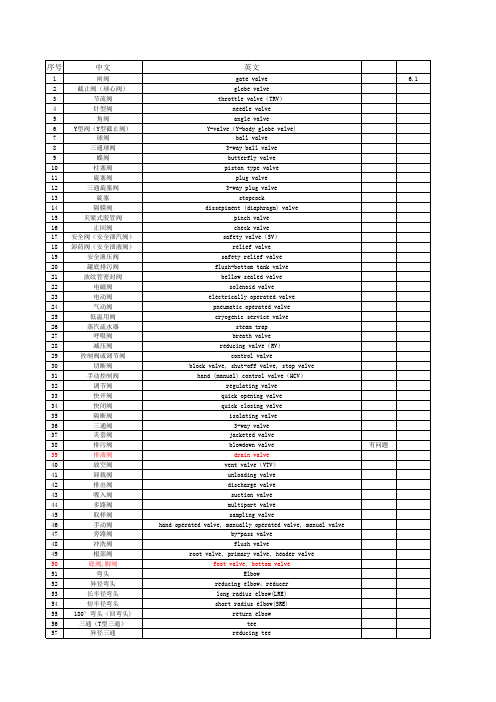
straight tee 45° tee true “T” cross reducer (RED) concentric reducer(CON) eccentric reducer(ECC) branch connection bolt circle diameter flange facing , facing of flange(FOF) plain face(PF) raised face(RF) male-female(seal contact)face(MFM) male face female face(FMF) tongue groove face(TGF) tongue face(TF) groove face(GF) ring joint face(RJF) flat face , full face(FF) smooth raised face(SRF) bolt hot(cold)tightening threaded cap(THDC) socket welded cap(SWC) threaded let(THLET) socket welded let(SWLET) gasket non-metallic jacket gasket metallic jacket gasket spiral wound gasket inner ring outer ring metallic gasket funnel drain funnel rupture disk(RP) restriction orifice(RO) mixing orifice hose connection(HC) metal hose rubber hose flexible hose quick coupling swivel joint reducer(RED) carbon steel(C.S) alloy steel structural alloy steel tool steel stainless steel(S.S) austenitic stainless steel martensitic stainless steel forged steel cast steel cast iron(C.I) grey cast iron malleable iron(M.I) nodular cast iron,nodular cast graphite iron high silicon cast iron
FURMAN 220V-240V专业产品线手册
www .furmansound .com 1技术FURMAN 与众不同FURMAN 超过三十五年来,Furman 一直是同行业中最值得信赖的名字,为音频、视频及广播专业人士在AC 电源调节、校准、平衡隔离变压器、时序和分布等各方面提供保证。
我们的客户包括可敬的职业音乐家、著名的录音室、商业承包商,以及在全世界举办大型巡回演唱会的演出团体。
他们选择Furman 产品,是因为我们拥有着长期可靠的声誉和在工程上的专业成就,一直专注于满足专业人士的特殊需求,了解这一行业中设备故障和停机是无法承受的。
长久以来我们的技术在全世界解决电源问题,挽回了数百万美元的设备,我们的技术创新将音频/视频系统的表现水平发挥到最高,这一切为Furman 带来了可靠的声誉。
我们的客户已离不开Furman 设备提供的安全纯净的电源。
特性及技术FURMAN 串联多级保护(SMP)音频/视频专业人士往往都无法接受断电停机,数据损坏和系统不稳定。
因此如SMP 这样的坚实可靠的专业级别瞬变电压浪涌抑制系统,是关键应用中的最佳选择。
使用SMP,将几乎没有任何停机故障时间。
实际上,该电路经测试,能够承受6000伏或3000安的脉冲而不会遭受任何损坏。
这远远超出了对典型的浪涌抑制器的要求。
然而鉴于Furman 的客户面对的极端条件和关键应用场合,SMP 电路的设计通过了严苛的测试,保证设备发生损坏或需要维修的可能性达到最低。
Furman 的SMP 技术是基于以一系列元件组成的网络来减缓潜在的灾难性浪涌冲击,捕获并以热量形式散发,并将剩下的能量吸收。
在使用多次6000V/3000A 的浪涌测试时,SMP 电路的最大允通电压在一条230V 线路上仅为376V Pk(峰值)/266V RMS(有效值)。
由于电路的良好设计,SMP 将不会随着时间劣化(与大多数标准浪涌抑制器不同),线性阻抗也呈最小增长(与许多高级浪涌抑制器不同)。
SMP 电路并不是简单保护电源不受灾难性的浪涌破坏,如被闪电击中,更进一步地为连接的设备提供最长限度的寿命保证。
浙江版CSC-241C数字式所(厂)用变保护测控装置说明书V1.00
重要提示
感谢您使用北京四方继保自动化股份有限公司的产品。为了安全、正 确、高效地使用本装置,请您务必注意以下重要提示:
1) 本说明书仅适用于浙江地区双保护 CT 的 CSC-241C 数字式厂(所) 用变保护测控装置。
3 装置硬件 ................................................................................................... 6
3.1 装置结构 ................................................................................................................................... 6 3.2 装置功能组件概述.................................................................................................................... 6 3.3 交流插件(AC)........................................................................................................................ 7 3.4 CPU 插件(CPU)....................................................................................................................... 7 3.5 逻辑插件(LOG)...................................................................................................................... 7 3.6 开出插件(DO)........................................................................................................................ 7 3.7 通信插件(COM)...................................................................................................................... 8 3.8 人机接口(MMI)...................................................................................................................... 8 3.9 电源插件(POW)...................................................................................................................... 8 3.10 插件布置 ................................................................................................................................... 8
中国电信2011年240V直流电源设备[汇编]
![中国电信2011年240V直流电源设备[汇编]](https://img.taocdn.com/s3/m/3074be3ccdbff121dd36a32d7375a417866fc1bb.png)
中国电信2011年240V直流电源设备集中采购标书文件项目二附件二技术规范书招标人:中国电信集团公司/中国电信股份有限公司招标代理机构:中捷通信有限公司二○一一年十一月目录1. 概述 (1)1.1. 定义 (1)1.2. 必须满足的技术标准/规范 (3)2. 主要技术要求 (5)2.1. 系统规格 (5)2.2. 环境条件 (5)2.3. 系统总体 (6)182.4. 交流配电屏.................................................................................................................232.5. 整流模块.....................................................................................................................2.6. 直流总配电屏 (25)2.7. 直流二级配电屏 (30)352.8. 监控模块.....................................................................................................................372.9. 外观与结构.................................................................................................................382.10. 包装与标志.................................................................................................................2.11. 节能环保.....................................................................................................................3940 3. 技术服务要求 .............................................................................................................................3.1. 设备检验.....................................................................................................................403.1.1. 工程技术协调会 (40)403.1.2. 出厂检验.................................................................................................................423.1.3. 供货 .........................................................................................................................42 3.1.4. 到货检验.................................................................................................................43 3.1.5. 到货抽检.................................................................................................................45 3.2. 工程服务.....................................................................................................................3.2.1. 安装调测服务(交钥匙工程) (45)3.2.2. 督导调测服务 (46)48 3.2.3. 督导服务.................................................................................................................48 3.3. 设备验收.....................................................................................................................48 3.3.1 初验 .............................................................................................................................49 3.3.2. 试运行.....................................................................................................................50 3.3.3. 终验 .........................................................................................................................51 3.4. 保修 .............................................................................................................................3.4.1. 保修期.....................................................................................................................51 3.4.2. 设备巡检服务 (51)52 3.4.3 故障件修理.................................................................................................................3.4.4. 故障响应及技术支持服务 (53)56 3.4.5 备件供应.....................................................................................................................57 3.4.6. 技术文件.................................................................................................................3.4.7. 软件补丁.................................................................................................................57 3.4.8. 特殊情况下的服务 (57)3.4.9. 电子文档提供服务 (58)3.4.10. 资料共享.................................................................................................................5858 3.5. 技术培训.....................................................................................................................3.5.1. 现场培训.................................................................................................................5859 3.5.2. 其它培训.................................................................................................................3.6. 其它服务要求 (60)1. 概述1.1. 定义1.本规范书为中国电信2011年240V直流电源设备项目二集中采购标书文件的技术要求和供货要求,提供给240V直流电源供应商(投标方)进行技术应答和报价书之用。
nVent RAYCHEM FrostGuard 240 V预装电热缆商品说明书

DESCRIPTIONnVent RAYCHEM FrostGuard 240 V preassembled electricheating cables are intended for installation on metal or plasticwater pipes for freeze protec t ion in commercial locations.FrostGuard 240 V heating cables are available in 6-, 12-, 18-, and24-foot lengths and each comes complete with a 6-ft cold lead.KIT CONTENTSItem Qty Description1FrostGuard preassembled heating cable3Wire connectorsADDITIONAL MATERIALS REQUIRED1 UL Listed or CSA Certified junction box suitable for wet or dryareas1 UL Listed or CSA Certified outlet bushing and fittingCable ties or glass-cloth tapeThermal pipe insulationFIRE AND SHOCK HAZARD. This product isan electrical device that must be installed correctlyto ensure proper operation and to prevent shock orfire. Read these important warnings and carefullyfollow all the installation instructions.• T o minimize the danger of fire from sustainedelectrical arcing if the heating cable is damagedor improperly installed, and to comply with therequirements of nVent, agency certifications,and the National Electrical Code, ground-faultequipment protection must be used on eachheating cable branch circuit. Arcing may not bestopped by conventional circuit protection.• U se only fire-resistant insulation materials suchas fiberglass wrap.• D o not damage the heating cable and cordconnector. Remove any damaged cables fromservice immediately.• D o not use any wire or metal clamps to attachthe cable to the pipe. Use tape (1/2 inch wide to 1inch wide) or plastic cable ties.• L eave these installation instructions with theuser for future reference.APPROVALS-WHEATING CABLE SELECTIONFrostGuard 240 V (FG2) heating cable selection for pipefreeze protection:Use the tables to the right to select the correct heating cable.Round up to the next pipe size if your pipe diameter isn’t shown.The charts assume the lowest ambient temperature is –20°F(–29°C), with a minimum of 1/2 in fiberglass insulation orequivalent. For protection to –40°F (–40°C), use 1 inch fiberglassinsulation or equivalent fire-resistant insulation.Add 1 foot to your pipe length for each valve or spigot on yourImportantor application, consult nVent at (800) 542-8936 for designTable 1 Metal Pipes Table 2 Plastic PipesAdd 1 foot to your pipe length for each valve or spigot on your pipe system.If cable selected is longer than the pipe, spiral it evenly along the entire pipe.Pipe length (ft)Pipediameter(in)Pipe length (ft)Pipediameter(in)211/2211/2240 V Preassembled Electric Heating Cables for Pipe FreezeProtection Installation InstructionsFROSTGUARD 240 V2 | GENERAL REQUIREMENTS:• FrostGuard heating cables are not intended for use inside any pipes, for freeze protection of liquids other than water, or for use in classified hazardous locations.• FrostGuard heating cables may be used on metal and plastic water pipes but not on flexible vinyl tubing (such as garden hoses).• Install with a minimum of 1/2 inch fire-resistant thermal insulation. Weatherproof the insulation if it might get wet.• Never use on any pipes that may exceed 150°F (65°C).GENERAL INSTRUCTIONS:• Install only in accessible locations; do not install behind walls or where the cable would be hidden.• Do not run the heating cable through walls, ceilings, or floors.• Connect only to junction boxes that have been installed in accordance with all prevailing national and local codes and standards and are protected from rain and other water.• Prior to installing the cable, remove any sharp surfaces on the pipe that might damage the heating cable.• Follow the specific installation instructions that begin below.• Follow the maintenance guidelines on page 3.CABLE TESTING AND MAINTENANCEUsing a 2500-Vdc megohmmeter, check the insulation resistance between the lead wires and ground wire during installation. Minimum reading should be 1000 megohms. The installer should record the original values for each circuit. Subsequent readings taken during regular maintenance schedules should be compared to the original value.If the readings should fall below 1000 megohms, replace the FrostGuard cable with a new unit. Do not attempt to repair the unit.WARNING: Fire and Shock Hazard. Damaged heating cable can cause electrical shock, arcing, or fire. Do not attempt to repairor energize damaged heating cable. Remove it at once and replace with a new length. | 3North AmericaTel: +1.800.545.6258Fax: +1.800.527.5703**********************Product SpecificationsFG2-6LFG2-12L FG2-18L FG2-24L Cable length (ft/m)6 (1.8)12 (3.7)18 (5.5)24 (7.3)Min. thermal output on a pipe at 40°F/4°C (watts)306090120Min. thermal output on a pipe at 0°F/–18°C (watts)4692138184Max. current draw on a pipe at 40°F/4°C (amps)0.210.430.640.85Max. current draw on a pipe at 0°F/–18°C (amps)0.320.640.961.28General Specifications for all FG2 Products Maximum cable width (inch/mm)0.45 (11.4)Maximum cable thickness (inch/mm)0.24 (6.1)Heating cable bus wire gauge (AWG)16Voltage rating (Vac)208–240Circuit breaker size 15 A max.Cold lead length (ft/m)6 (1.83)Maximum exposure temperature 150°F (65°C)Minimum installation temperature 5°F (–15°C) Minimum bend radius (inch/mm)5/8 (16)Electrical classification Nonhazardous areas only Exposure to chemicalsNone。
240V高压直流说明书

辅助电源在输入三相无源PFC之后,DC/DC变换器之前,利用三相无源PFC的直流输出,产生控制电路所需的各路电源。输入检测电路实现输入过欠压、缺相等检测。DC/DC的检测保护电路包括输出电压电流的检测,散热器温度的检测等,所有这些信号用以DC/DC的控制和保护。
5)过温保护
模块的进风口被堵住或环境温度过高导致模块内部的温度超过设定值时,模块会过温保护,模块面板的保护指示灯(黄色)亮,模块无电压输出。当异常条件清除、模块内部的温度恢复正常后,模块将自动恢复为正常工作。
2.其它功能
1)风扇温度控制
模块采用温度和电流联合控制风扇转动的方式。风扇转速分为半转和全转二档,通过对输出电流和模块温度综合考虑进行风扇调速控制。
图1 RM240D20-Ⅲ模块原理图
RM24020-Ⅲ模块由三相无源PFC和DC/DC两个功率部分组成。在两功率部分之外还有辅助电源以及输入输出检测保护电路。
前级三相无源PFC电路由输入EMI和三相无源PFC组成,用以实现交流输入的整流滤波和输入电流的校正,使输入电路的功率因素大于0.92,以满足DL/T781-2001中三相谐波标准和GB/T 17794.2.2-2003中相关EMI、EMC标准。
通讯接口
12
DATA+
弱信号端,模块和上级设备的通讯接口,为串行异步传输模式,通信方式为RS485
15
DATA-
均流接口
21
SHARE+
弱信号端,两个或者两个以上的模块输出并联时,需要将此端并联,以实现模块均分负载功能
特瑞堡中文泛塞密封

- 1、下载文档前请自行甄别文档内容的完整性,平台不提供额外的编辑、内容补充、找答案等附加服务。
- 2、"仅部分预览"的文档,不可在线预览部分如存在完整性等问题,可反馈申请退款(可完整预览的文档不适用该条件!)。
- 3、如文档侵犯您的权益,请联系客服反馈,我们会尽快为您处理(人工客服工作时间:9:00-18:30)。
Temperature rating
Ordering information
Standard colours
Operating temperature range:-30°C to +105°C Minimum recovery temperature:
+150°C
Inside diameter Wall thickness Standard package D (min)
Expanded as supplied d (max)Recovered after heating W (nom)Recovered after heating Spool quantity mm mm mm m Ordering description 1.60.80.4100TRV-160-colour code 2.4 1.20.5100TRV-240-colour code 3.2 1.60.5100TRV-320-colour code 4.8 2.40.5100TRV-480-colour code 6.4 3.20.5100TRV-620-colour code 9.5 4.50.6100TRV-950-colour code 12.7 6.40.850TRV-1270-colour code 15.07.50.850TRV-1500-colour code 19.09.50.850TRV-1900-colour code 25.412.7 1.050TRV-2540-colour code 32.016.0 1.050TRV-3200-colour code 38.019.0 1.050TRV-3800-colour code 51.025.5 1.050TRV-5100-colour code 76.038.1 1.025TRV-7625-colour code 102.0
51.0
1.3
25
TRV-10200-colour code
Colour Black Red Yellow Blue Green White Code
2
4
5
6
9
•Self extinguishing •Non-irradiated •Flexible
•Good mechanical performance
TRV
Electrically insulating PVC heat-shrinkable tubing
TRV is a self extinguishing, flexible, non-irradiated, Poly Vinyl Chloride heat-
shrinkable tubing. The product provides excellent mechanical performance and is resistant to a wide range of chemicals and solvents.
TRV finds extensive use in the Automotive and Commercial Electronics industries.
Raychem Interconnect Cheney Manor Industrial Estate Swindon, Wiltshire SN2 2QE Tel:(44)-1793-528171 Fax:(44)-1793-616652All of the above information, including illustrations, is believed to be reliable. Users, however, should independently evaluate the suitability of each product for their application. Tyco Electronics makes no warranties as to the accuracy or completeness of the information and disclaims any liability regarding its use. Tyco Electronics only obligations are those in the Standard Terms and Conditions of Sale for this product and in no case will Tyco Electronics be liable for any incidental, indirect or consequential damages arising from the sale, resale, use or misuse of the product. Tyco Electronics Specifications are subject to change without notice. In addition Tyco Electronics reserves the right to make changes in materials or processing, without notification to the Buyer, which do not affect compliance with any applicable specification.
TRV
RI0037.1299 Raychem and TRV are trademarks of Raychem Interconnect, a division of Tyco Electronics Corporation.
Performance
Specifications Heat ageing:168 h at 136°C UL 224 Corrosion resistance:No corrosion ASTM D2671 Dielectric strength:15 MV/m min IEC 243
Fluid resistance 24h at 23°C, ISO 37:Tensile strength 12 MPa (min)
Elongation 150% (min)
Test Fluids:
IRM 902
Lubricating oil 0-149
Anti-icing fluid
Flammability:Pass UL 224 VW1
For full product performance details consult Raychem Specification RK 6147/1. Raychem Specification RK 6147/1.。
