VFM05-S050中文资料
OX5040中文资料
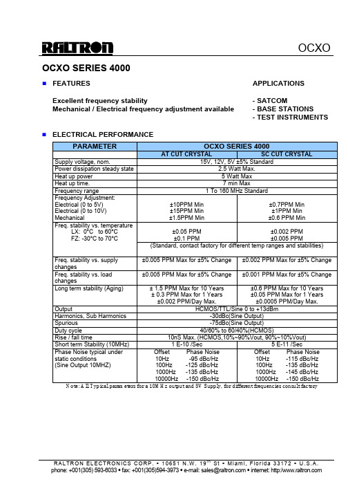
OCXO SERIES 4000n FEATURES APPLICATIONS Excellent frequency stability - SATCOMMechanical / Electrical frequency adjustment available - BASE STATIONS- TEST INSTRUMENTSn ELECTRICAL PERFORMANCEPARAMETER OCXO SERIES 4000AT CUT CRYSTAL SC CUT CRYSTAL Supply voltage, nom. 15V, 12V, 5V ±5% StandardPower dissipation steady state 2.5 Watt Max.Heat up power 5 Watt MaxHeat up time. 7 min MaxFrequency range 1 To 160 MHz StandardFrequency Adjustment:Electrical (0 to 5V) Electrical (0 to 10V) Mechanical ±10PPM Min±15PPM Min±1.5PPM Min±0.7PPM Min±1PPM Min±0.6 PPM Min±0.05 PPM±0.1 PPM±0.002 PPM±0.005 PPMFreq. stability vs. temperatureLX: 0°C to 60°CFZ: -30°C to 70°C(Standard, contact factory for different temp ranges and stabilities) Freq. stability vs. supplychanges±0.005 PPM Max for ±5% Change ±0.002 PPM Max for ±5% ChangeFreq. stability vs. loadchanges±0.005 PPM Max for ±5% Change ±0.001 PPM Max for ±5% ChangeLong term stability (Aging) ± 1.5 PPM Max for 10 Years± 0.3 PPM Max for 1 Years±0.002 PPM/Day Max. ±0.6 PPM Max for 10 Years ±0.05 PPM Max for 1 Years ±0.0005 PPM/Day Max.Output HCMOS/TTL/Sine 0 to +13dBm Harmonics, Sub Harmonics -30dBc(Sine Output)Spurious -75dBc(Sine Output)Duty cycle 40/60% to 60/40%(HCMOS)Rise / fall time 10nS Max. (HCMOS,10%~90%Vout, 90%~10%Vout) Short term Stability (10MHz) 1 E-10 /Sec 5 E-11 /SecPhase Noise typical under static conditions(Sine Output 10MHZ) Offset Phase Noise10Hz -95 dBc/Hz100Hz -125 dBc/Hz1000Hz -135 dBc/Hz10000Hz -150 dBc/HzOffset Phase Noise10Hz -115 dBc/Hz100Hz -135 dBc/Hz1000Hz -145 dBc/Hz10000Hz -150 dBc/HzNote: All Typical parameters for a 10MHz output and 5V Supply, for different frequencies consult factoryn HOW TO ORDER (PART NUMBER)Prefix Output Type Cut TypeSeries Revision Temperature Range Stability FrequencySupply Voltage OX1:TTL 2:HCMOS 3:ACMOS 4:LVCMOS 5:100K ECL 6:SINE 7:10K ECL 8: PECL 9:CUSTOM0:AT (No Vcontrol ) 1: SC (No Vcontrol ) 2: AT (Mechanical Adj) 3: SC (Mechanical Adj) 4: AT (Elect Vcontrol) 5: SC (Elect Vcontrol) 6: AT (Mech & Elect.) 7: SC (Mech & Elect.)4X:4000 40:Height=1”/25.4mm41:Height=2”/50.8mm42:Height=4”/101.6mm44~49:Odd HeightAFirst letter Lowest Temperature,Second letter Highest Temperature: From A=-55°C to Z=+70°C, Then: 1=+75°C, 2=+80°C, 3=+85°C… in 5°C steps Example: LZ: +0°C to +70°C LX: +0°C to +60°C FZ: -30°C to +70°C D3: -40°C to +85°CValue x10E-2 in PPMExample 28=0.28PPM 10= 0.1PPMIn MHZ5: 5V 12; 12V 15; 15V。
日本油封精工O型圈手册

耐矿物油 用
耐汽油用
耐动植物 用油
耐热用
耐热用
硬度 类型 A硬度计
A70±5
A90±5 A70±5
A70±5
A70±5
A70±5
拉力强度
(MPa)最
9.8
14
9.8
9.8
3.4
9.8
小
常态 伸长(%) 最小
250
100
200
150
60
200
拉力应力 (MPa)最小
2.7
‐
2.7
2.7
‐
1.9
(100%伸 长的时候)
23℃ × 70hr
‐
175℃
‐
×
70hr
硬度变化 (Hs)
-15~0
-10~+5
-20~0
‐
‐
-10~+5
拉力强度
变化率(%) -25
-35
-45
‐
‐
-20
最大
伸长变化 率(%)
-35
-35
-45
‐
‐
-20
体积变化 率(%)
0~+20
0~+20
0~+30
‐
‐
-5~+5
低温 弯曲 试验
温度以及 时间
硬度变
化(Hs)
+10
+15
+15
+10
最大
老化试验
拉力强
度变化 率(%)最
-30
-20
-15
-10
大
伸长变
化率(%)
-40
-50
-40
Agilent I O Hardware 数据手册说明书
82357A technical specificationsGeneral requirementsMinimum system requirements Windows 98(SE)/Me 2•PCI IEEE-488 interface for PCs•Transfer rates up to 900 KB/s•Dual processor support onWindows 2000/XPBest for•Maximum GPIB throughput forall configurationsHigh performance for manufacturingtest applicationsThe 82350B is Agilent’s highest-performance GPIB interface. Witha direct PCI computer connection,transaction overhead is minimizedfor the best overall performance.The 82350B card de-couples GPIBtransfers from PCI bus transfers.Buffering provides I/O and systemperformance that is superior to directmemory access (DMA). The hardwareis software configurable and compati-ble with the Plug-and-Play standardfor easy hardware installation. TheGPIB interface card plugs into a 5 voltPCI slot in the backplane of your PC.For programming capability youhave access with the latest versionof IO Libraries suite, version 14.1, toprogram in all standard developmentenvironments. Agilent’s IO LibrariesSuite 14.1 is easy to use and workswith virtually any vendor’s instrumentor T&M programming softwareapplication and includes automaticconfiguration for Agilent or NI VISA,NI-488.2, VISA COM or T&M ToolkitDirect IO. Even if you use NI IO soft-ware Agilent will configure automati-cally so as a user you do not have tobe concerned with the behind-the-scenes details.382350B technical specifications General requirements Minimum system requirements Windows 98(SE)/Me (note 98 supported with version 14.0 only)/2000/XP Software required Agilent IO Libraries Suite (included); see requirements on page 1PCI bus slot 5-V PCI slot, 32 bits Supported standards PCI rev 2.2IEEE 488.1 and IEEE 488.2 compatible General characteristics Power Backplane +5 V PCI Connectors Standard 24-pin GPIB (IEEE-488)+5V PCI Maximum data rate More than 900 KB/s Maximum instrument connection 14 instruments—daisy chain via GPIB Buffering Built-in Configuration Plug-and-Play EMC and safety *IEC 61326-1Group 1, Class A IEC 61010-1Warranty 1 year Dimensions Length, width, and height 122 mm (L) x 122 mm (W) x 22 mm (H) (a full-height PCI card)Weight 0.091 kg Environmental specifications Operating environment 0°C to 55°C Operating humidity Up to 90% at 40°C non-condensing Storage environment -40°C to +70°C Storage humidity Up to 90% at 65°C non-condensing * Additional detail and information in the Declaration of ConformityThis traditional GPIB connection still offers the highest throughputE5810A technical specifications 45USB port on your PC to up to fourRS-232 instruments or devices•Fully compatible with WindowsCOM driver and industry-standardVISA I/O software.Best for•Easy connection to RS-232 devices•Notebook computer RS-232connectionsAdd four serial ports in minutesThe Agilent E5805A USB/4-portRS232 interface provides a directconnection from the USB port onyour notebook or desktop PC to up tofour RS-232 instruments or devices.There are no switches to set, no PCcards to install, and no external powersupplies are required. Simply installthe driver and plug in the E5805AUSB 4-port RS232 interface to addfour RS-232 ports to your computer.Since the E5805A is a standardPlug-and-Play device, your computerautomatically detects and configuresit when it is connected to your com-puter USB port. You can interface upto four devices, with baud rates up to230 Kb/s per serial port. The E5805Aprovides four DB9 serial connectorsand ships with a 1.8-meter USB cable.E5813A technical specificationsGeneral requirements67Agilent Technologies’ Test and Measurement Support, Services, and Assistance Agilent Technologies aims to maximize the value you receive, while minimizing your risk and problems. We strive to ensure that you get the test and measurement capabilities you paid for and obtain the support you need. Our extensive support resources and services can help you choose the right Agilent products for your applications and apply them successfully. Every instru-ment and system we sell has a global warranty. Support is available for at least five years beyond the production life of the product. Two concepts underlie Agilent’s overall support policy: “Our Promise” and “Your Advantage.”Our Promise Our Promise means your Agilent test and measurement equipment will meet its advertised performance and functionality. When you are choosing new equipment,we will help you with product information, including realistic performance specifications and practical recom-mendations from experienced test engineers. When you receive your new Agilent equipment, we can help verify that it works properly, and help with initial product operation.Your AdvantageYour Advantage means that Agilent offers a wide range of additional expert test and measurement services, which you can purchase according to your unique technical and business needs. Solve problems efficiently and gain a competitive edge by contracting with us for calibration, extra-cost upgrades, out-of-warranty repairs, and onsite education and training, as well as design, system integration, project management, and other professional engineering services. Experienced Agilent engineers and techni-cians worldwide can help you maximize your productivity,optimize the return on investment of your Agilent instruments and systems, and obtain dependable measurement accuracy for the life of those products./find/emailupdates Get the latest information on the products and applications you /find/openAgilent Open simplifies the process of connecting and programming test systems to help engineers design,validate and manufacture electronic products. Agilentoffers open connectivity for a broad range of system-ready instruments, open industry software, PC-stan-dard I/O and global support, which are combined to more easily integrate test system development. For more assistance with your test & measurement needs or to find your local Agilent office go to /find/contactus Microsoft, Windows and Visual Studio are U.S. registered trademarks of Microsoft Corporation.Pentium is a U.S. registered trademark of Intel Corporation.Product specifications and descriptions in this document subject to change without notice.© Agilent Technologies, Inc. 2005Printed in USA, August 5, 20055989-1889EN Agilent Open Agilent Email Updates •Agilent E2094N IO Libraries Suite, Data sheet pub no. 5989-1439EN •Modern Connectivity–Using USB and LAN I/O Converters, Application note 1475-1pub no. 5989-0123EN •Simplified PC Connections for GPIB Instruments,Application note 1409-1, pub no. 5988-5897EN •Using LAN in Test Systems: The Basics,Application note 1465-9, pub no. 5989-1412ENpub no. 5989-1417EN •Computer I/O Considerations, Application note 1465-2, pub no. 5988-9818EN Learn more at /find/io-ds Join the Agilent Developer Network to get updated I/O software, instrument drivers, code examples,white papers, and more! Registration is easy and free at /find/adn.。
Y-050润滑油
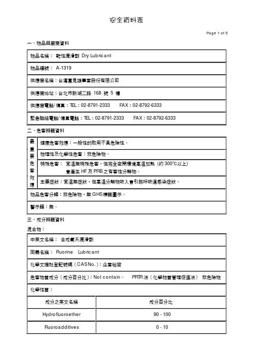
一、物品與廠商資料物品名稱: 乾性潤滑劑 Dry Lubricant 物品編號: A-1319供應商名稱:台灣富見雄事業股份有限公司 供應商地址:台北市新湖二路 168 號 5 樓供應商電話/傳真:TEL :02-8791-2333 FAX :02-8792-6333 緊急聯絡電話/傳真電話:TEL :02-8791-2333 FAX :02-8792-6333 二、危害辨識資料 健康危害效應:一般性的取用不具危險性。
物理性及化學性危害:非危險物。
特殊危害: 常溫無特殊危害,但完全密閉環境高溫加熱 (約300℃以上)會產生HF 及PFIB 之有害性分解物。
最重要危害效應主要症狀:常溫無症狀,但高溫分解物吸入會引起呼吸道感染症狀。
物品危害分類:非危險物,無GHS 標識圖示。
警示語:無。
三、成分辨識資料 混合物:中英文名稱: 合成氟系潤滑劑 同義名稱: Fluorine Lubricant化學文摘社登記號碼(CAS No.):企業秘密危害物質成分(成分百分比):Not contain 。
PRTR 法(化學物質管理促進法) 非危險物 化學性質:成分之英文名稱 成分百分比 Hydrofluoroether 90 - 100 Fluoroadditives0 - 10四、急救措施不同暴露途徑之急救方法:(常溫使用)˙ 吸入:若有症狀出現,緊急移至安靜涼爽、通風良好的地方。
˙ 皮膚接觸:移除受污染衣物後,用清水及肥皂清洗。
˙ 眼睛接觸:直接以清水沖洗至少15分鐘,再請眼科醫師檢查。
˙ 食入:一般不需特別應急措施;用大量乾淨之飲用水漱口亦可。
˙ 有關應急措施特記事項:本潤滑劑在室溫中對眼睛、皮膚、呼吸道基本上並無刺激作用,但在使用或保存過程中,若不慎混入外來之污染異物,造成本劑污染,而使身體沾附,請儘速將沾附於眼睛、皮膚、呼吸道的污染異物清除,這是最基本的緊急處理方法。
對急救人員之防護:一般正常裝備即可。
VN05H中文资料
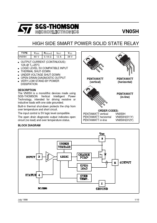
VN05HHIGH SIDE SMART POWER SOLID STATE RELAYJuly 1998BLOCK DIAGRAMsOUTPUT CURRENT (CONTINUOUS):12A @ T c =25o Cs LOGIC LEVEL 5V COMPATIBLE INPUT s THERMAL SHUT-DOWNs UNDER VOLTAGE SHUT-DOWNs OPEN DRAIN DIAGNOSTIC OUTPUT sVERY LOW STAND-BY POWER DISSIPATIONDESCRIPTION The VN05H is a monolithic devices made using SGS-THOMSON Vertical Intelligent Power Technology, intended for driving resistive or inductive loads with one side grounded.Built-in thermal shut-down protects the chip from over temperature and short circuit.The input control is 5V logic level compatible.The open drain diagnostic output indicates open circuit (no load) and over temperature status.1/10VN05HABSOLUTE MAXIMUM RATINGCONNECTION DIAGRAMSCURRENT AND VOLTAGE CONVENTIONSVN05H THERMAL DATAELECTRICAL CHARACTERISTICS (V CC = 9 to 36 V; -40 ≤ T j≤ 125 o C unless otherwise specified) POWERSWITCHINGLOGIC INPUTELECTRICAL CHARACTERISTICS (Continued)PROTECTION AND DIAGNOSTICSexceed 10 mA at the input pin.(•) Status determinaion > 100 µs after the switching edge.Note 1: Above V CC = 36V the output voltage is clamped to 36V. Power dissipation increases and the device turns off it junction temperature reaches thermal shutdown temperature.FUNCTIONAL DESCRIPTIONThe device has a diagnostic output which indicates open circuit (no load) and over temperature conditions. The output signals are processed by internal logic.To protect the device against short circuit and over-current condition the thermal protection turns the integrated Power MOS off at a minimum junction temperature of 140 o C. When the temperature returns to about 125 o C the switch is automatically turned on again. To ensur the protection in all V CC conditions and in all the junction temperature range it is necessary to limit the voltage drop across Drain and Source (pin 3and 5) at 29 V. The device is able to withstand a load dump according the test pulse 5 at level III of the ISO TR/1 7631.Above V CC = 36V the output voltage is clamped to 36V. Power dissipation increases and the device turns off if junction temperature reaches thermal shutdown temperature.PROTECTING THE DEVICE AGAINST REVERSE BATTERYThe simplest way to protect the device against a continuous reverse battery voltage (-26V) is toinsert a Schottky diode between pin 1 (GND) and ground, as shown in the typical application circuit (fig. 3).The consequences of the voltage drop across this diode are as follows:-If the input is pulled to power GND, a negativevoltage of -V F is seen by the device. (V IL , V IH thresholds and V STAT are increased by V F with respect to power GND).-The undervoltage shutdown level is increasedby V F .If there is no need for the control unit to handle external analog signals referred to the power GND, the best approach is to connect the reference potential of the control unit to node [1](see application circuit infig. 4), which becomes the common signal GND for the whole control board.In this way no shift of V IH , V IL and V STAT takes place and no negative voltage appears on the INPUT pin; this solution allows the use of a standard diode, with a breakdown voltage able to handle any ISO normalized negative pulses thatoccours in the automotive environment.VN05HTRUTH TABLEFigure 1:WaveformsFigure 2:Over Current Test CircuitVN05HFigure 3:Typical Application Circuit With A Schottky Diode For Reverse Supply ProtectionFigure 4:Typical Application Circuit With Separate Signal GroundVN05HVN05HVN05HVN05HInformation furnished is believed to be accurate and reliable. However, STMicroelectronics assumes no responsibility for the consequences of use of such information nor for any infringement of patents or other rights of third parties which may result from its use. No license is granted by implication or otherwise under any patent or patent rights of STMicroelectronics. Specification mentioned in this publication are subject to change without notice. This publication supersedes and replaces all information previously supplied. STMicroelectronics products are not authorized for use as critical components in life support devices or systems without express written approval of STMicroelectronics.The ST logo is a trademark of STMicroelectronics © 1998 STMicroelectronics – Printed in Italy – All Rights ReservedSTMicroelectronics GROUP OF COMPANIESAustralia - Brazil - Canada - China - France - Germany - Italy - Japan - Korea - Malaysia - Malta - Mexico - Morocco - The Netherlands -Singapore - Spain - Sweden - Switzerland - Taiwan - Thailand - United Kingdom - U.S.A..VN05H。
LH05-10B05中文资料

The copyright and authority for the interpretation of the products are reserved by Mornsun
Output (Vo2/Io2)
Ripple and Noise (Typ.)
Efficiency (%)(Typ.)
70
110VAC 10A, typ 10A, typ 10A, typ 16A, typ
230VAC 20A, typ 20A, typ 20A, typ 30A, typ
1A/250V slow blow 2A/250V slow blow 3.15A/250V slow blow
The copyright and authority for the interpretation of the products are reserved by Mornsun
3. 3V/ 4100m A 5V/3500mA 12V/1600mA 15V/1300mA 24V/850mA
LH20-10A05Biblioteka +5V/2000mA
-5V/2000mA
LH20-10A12
+12V/830mA
-12V/830mA
LH20-10A15
+15V/650mA
-15V/650m a
70x48x23.5mm LH20-10C0505-05*
5V/1200mA 5V/1000mA 5V/900mA 5V/1000mA
UL/CE UL/CE UL/CE UL/CE
LH10-10D0505-02 LH10-10D0512-02 LH10-10D0515-02 LH10-10D0524-02
RSO-0505S;RSO-0505D;RSO-2412DZ;RSO-2405SZH3;RSO-243.3S;中文规格书,Datasheet资料

ECONOLINEDC/DC-Converterwith 3 year WarrantyRSO E-95REV:1/2011EN-60950-1 Certified EN-60601-1 CertifiedDescriptionHigh-power-density, an industrial temperature range of -40°C to +85°C and extra features like On-Off-control are just some of the characteristics of this converter, ideal for highly sophisticated industrial-designs. The RSO series is available with isolation of 2kV or 3kV by chosing option "/H2"or "/H3" in which case it is also ideal for medical applications which additionally require EN-60601-1 certification. The standard version offers 2:1 input voltage range, while the “Z” version features 4:1input voltage range, which includes an input voltage range covering both 5V and 12V supplies.1 WattSIP8 Isolated Single &Dual Output●2:1 and 4:1 Wide Input Voltage Ranges ●1kVDC, 2kVD or 3kVDC Isolation ●UL94V-0 Package Material●Certified for Medical Applications ●Continuous Short Circuit Protection ●Low Noise●No External Capacitor needed ●Efficiency to 83%FeaturesRegulated ConvertersSelection GuidePart NumberInput Rated Output Output Current Efficiency Max Voltage Range Voltage typ.CapacitiveSIP8(VDC)(VDC)(mA)(%)Load (1)RSO-xx3.3S* 4.5-9**, 9-18 3.330068-723300µF18-36, 36-7270RSO-xx05S* 4.5-9**, 9-18520073-751200µF18-36, 36-7275-78RSO-xx09S* 4.5-9**, 9-18911174-78680µF18-36, 36-7278-81RSO-xx12S* 4.5-9**, 9-18128375-80680µF18-36, 36-7280-83RSO-xx15S* 4.5-9**, 9-18156775-80680µF18-36, 36-7280-83RSO-xx3.3D* 4.5-9**, 9-18±3.3±15068-72±1500µF18-36, 36-7270RSO-xx05D* 4.5-9**, 9-18±5±10073-75±470µF18-36, 36-7275-76RSO-xx09D* 4.5-9**, 9-18±9±5674-78±470µF18-36, 36-7278RSO-xx12D* 4.5-9**, 9-18±12±4275-79±330µF18-36, 36-7279-80RSO-xx15D* 4.5-9**, 9-18±15±3475-79±330µF18-36, 36-7279-80RSO-xx3.3SZ*9-36 3.330068-703300µF18-7270RSO-xx05SZ* 4.5-18**, 9-36520073-781200µF18-7275RSO-xx09SZ* 4.5-18**, 9-36911175-81680µF18-7278RSO-xx12SZ* 4.5-18**, 9-36128377-83680µF18-7280RSO-xx15SZ* 4.5-18**, 9-36156778-83680µF18-7280RSO-xx3.3DZ*9-36±3.3±15070-74±1500µF18-7270RSO-xx05DZ* 4.5-18**, 9-36±5±10073-77±470µF18-7275RSO-xx09DZ* 4.5-18**, 9-36±9±5674-78±470µF18-7278RSO-xx12DZ* 4.5-18**, 9-36±12±4275-80±330µF18-7280RSO-xx15DZ* 4.5-18**, 9-36±15±3475-80±330µF18-7280No suffix is standard isolation (1kVDC) e.g, RSO-0505S*add suffix /H2 or /H3 for 2kVDC or 3kVDC isolation, e.g, RSO-0505S/H2, RSO-0505DZ/H3** derate to 75% if Vin<5V, 12V 4:1 input also requires an external 10µF input capacitor.Refer to Application NotesRoHS2002/95/EC6/6O u t p u t P o w e r (%)100602040Operating Temperature °C80Derating-Graph(Ambient T emperature)2:1Input 4:1Input (RS0-S/D) (RSO-SZ/DZ)xx = 4.5-9Vin = 05 xx = 4.5-18Vin = 12xx = 9-18Vin = 12 xx = 9-36Vin = 24 xx = 18-36Vin = 24 xx = 18-72Vin = 48xx = 36-72Vin = 48/E-96REV: 1/2011R S 0Input Voltage Range 2:1 and 4:1Output Voltage Accuracy ±2% typ.Line Voltage Regulation 2:1±0.2% max.4:1±0.5% max.Load Voltage Regulation 2:1±0.4% max.(10% to 100% full load)4:1±0.5% typ.Minimum Load0%Output Ripple and Noise (20MHz limited)50mVp-p max.Operating Frequency 2:1200kHz min. / 500kHz max.4:1100kHz min. / 800kHz max.Efficiency at Full Load See Selection GuideQuiescent Current RSO-05xxS_D, SZ_DZ 40mA typ.Nominal input Voltage RSO-12xxS_D32mA typ.(Standard, /H2 and /H3)RSO-24xxS_D, SZ_DZ 25mA typ.RSO-48xxS_D, SZ_DZ15mA typ.CTRL Pin drive current /see Notes)3mA typ, 6mA max.Quiescent Input Current when Converter is OFF 10mA max.Isolation Voltage Standard (tested for 1 second)1000VDC(rated for 1 minute)500VAC / 60Hz/H2 Version (tested for 1 second)2000VDC(rated for 1 minute)1000VAC / 60Hz/H3 Version (tested for 1 second)3000VDC(rated for 1 minute)1500VAC / 60HzIsolation Capacitance Standard 2:1 Single 10pF min. / 40pF typ. / 60pF max.Isolation Capacitance /H2 and /H32:1 Single 5pF min. / 30pF typ. / 60pF max.Isolation Capacitance Standard 2:1 Dual 120pF min. / 170pF typ. / 250pF max.Isolation Capacitance /H2 and /H32:1 Dual 5pF min. / 30pF typ. / 60pF max.Isolation Capacitance Standard 4:1 Single/Dual 200pF max.Isolation Capacitance /H2 and /H34:1 Single/Dual 30pF max.Isolation Resistance >1G Ωmin.Short Circuit ProtectionContinuousOperating Temperature Range (free air convection)-40°C to +85°C (see Graph)Storage Temperature Range -55°C to +125°CRelative Humidity 95% RH Package Weight 4.7gPacking Quantity 22 pcs per TubeMTBF (+25°C)using MIL-HDBK 217F 1685 x 103 hours (+85°C)using MIL-HDBK 217F254 x 103 hoursSpecifications (Core Operating Area)measured at T A = 25°C, nominal input voltage, full load and after warm-up time unless otherwise specifiedTypical ApplicationE f f i c i e n c y %100040%0%100%40Efficiency / Load 60%80%20%206080Total Output current (%)RSO-24xxS}Detailed Information seeApplication Notes chapter "MTBF"-Vin-Vout+Vout+VinE f f i c i e n c y %100040%0%100%40Efficiency / Load 60%80%20%206080Total Output current (%)RSO-1205SZ/RSO E-97REV:1/20113rd angleprojection8 PIN SIP PackageXX.X ± 0.5 mm XX.XX ± 0.25 mmPin 8 (NC*)This pin is used internally and must have no external connection.Pin 5 (NC)Not connected internally.Pin 3 (CTRL)This pin provides an Off function which puts the converter into a low power mode. When the pin is ‘high’ the converter is OFF and when the pin is high ‘Z’ the converter is ON. There is no allowed low state for this pin.Package Style and Pinning (mm)Single Output Recommended Footprint DetailsPin Connections Pin #SingleDual1 –Vin –Vin2 +Vin +Vin 3CTRL CTRL 5NC NC 6+Vout +Vout7 –Vout C om8NC*–VoutNC = No ConnectionNC* = NC, but no external Connection allowed.CTRL Examples+VoutCtrlTTL Remote CTRL CircuitVoltage to be applied via a limiting resistor with a recom-mended value of 1K for RSO-05xx; 3.3K for RSO-12xx;4.7K for RSO-24xx and 10K for RSO-48xx.Control Pin Input Current: 10mA Voltage Set Point Accuracy with external input/outputcapacitors refer to typ. ± 1%recommended test circuit: max. ±2%Control Pin (CTRL) Input Current, control voltage applied via 1K resistor,output voltage must typ. 3mA reduce to 0V: max. 6mA+VoutIsolated Remote CTRL CircuitNotes Note 1Maximum capacitive load is defined as the capacitive load that will allow start up in under 1 second without damage to the converterCertifications EN General Safety Report: IL-R7109EN60950-1:2001 + A11:2004EN Medical SafetyReport: PS071001601EN60601-1:1990 + A11:1996/分销商库存信息:RECOM-POWERRSO-0505S RSO-0505D RSO-2412DZ RSO-2405SZ/H3RSO-243.3S RSO-1212S RSO-2412D RSO-2415D RSO-0505S/H2 RSO-2405SZ/H2RSO-2405DZ RSO-0505S/H3 RSO-2412SZ/H3RSO-1205DZ RSO-1212DZ RSO-2415DZ/H3RSO-2412DZ/H3RSO-4812SZ/H3 RSO-4805SZ/H3RSO-4812DZ/H3RSO-4815DZ/H3 RSO-2409S RSO-1209S RSO-1215S RSO-123.3S RSO-2415S RSO-2412S RSO-2405S RSO-0509S RSO-0512S RSO-053.3S RSO-2409SZ RSO-2412SZ RSO-2415SZ RSO-243.3SZ RSO-4805S RSO-4809S RSO-4812S RSO-4815S RSO-483.3S RSO-1205S RSO-0509D RSO-0509S/H2RSO-0512D RSO-0512S/H2 RSO-0515D RSO-0515S/H2RSO-053.3D RSO-053.3S/H2RSO-2409DZ RSO-2409SZ/H2 RSO-2412SZ/H2RSO-2415DZ RSO-2415SZ/H2 RSO-243.3DZ RSO-243.3SZ/H2RSO-1205S/H3 RSO-1209S/H3RSO-1212S/H3RSO-1215S/H3 RSO-123.3S/H3RSO-2405S/H2RSO-2409S/H2 RSO-2412S/H2RSO-2415S/H2RSO-243.3S/H2 RSO-2405D RSO-2409D RSO-243.3D RSO-2405D/H2RSO-2409D/H2RSO-2412D/H2 RSO-2415D/H2RSO-243.3D/H2RSO-1205S/H2 RSO-1209S/H2RSO-1212S/H2RSO-1215S/H2 RSO-123.3S/H2RSO-1205D RSO-1209D RSO-1212D RSO-1215D RSO-123.3D RSO-0515S RSO-2405SZ RSO-1209SZ RSO-1215SZ RSO-123.3SZ RSO-0509S/H3 RSO-0512S/H3RSO-0515S/H3RSO-053.3S/H3 RSO-1205D/H2RSO-1209D/H2RSO-1212D/H2 RSO-1215D/H2RSO-123.3D/H2RSO-2409SZ/H3 RSO-2415SZ/H3RSO-243.3SZ/H3RSO-1205SZ/H2 RSO-1209DZ RSO-1209SZ/H2RSO-1212SZ/H2 RSO-1215DZ RSO-1215SZ/H2RSO-123.3DZ RSO-123.3SZ/H2RSO-4805SZ RSO-4809SZ RSO-4812SZ RSO-4815SZ RSO-483.3SZ RSO-2409S/H3RSO-2412S/H3RSO-2415S/H3 RSO-243.3S/H3RSO-2405D/H3RSO-2409D/H3 RSO-2412D/H3RSO-2415D/H3RSO-243.3D/H3 RSO-4805D RSO-4805S/H2RSO-4809D RSO-4809S/H2RSO-4812D RSO-4812S/H2 RSO-4815D RSO-4815S/H2RSO-483.3D。
IOS-MAT-0054_CNv5
参考
本技术规范中化学品要求和测试所引用的标准,如欧盟指令,都适用标准、指令的最新版本,除非 另有说明。
本资料仅供参考,英文版本 IOS-MAT-0054 具有最终法律效力。
1 of 23 2009-10-26 Elsa Hou 译稿
表2. 实木、木基材料和天然材料的要求
物质
要求
测试方法
文件
硼及其化合物
不允许使用硼及其化合物。
在实木(包括实木拼板)、 污染限值:硼及其化合物的迁移 天然纤维、胶合板、层压 值:30 mg 硼/kg 板/弯曲木中
如果木材有涂层,在 SD 测试前应去除涂层。
DIN 53160(用人工 合成汗液进行萃取, 16小时,23 °C), 然后依照EN ISO 11885(ICP/AES分 析)
IOS-MAT-0054 第五版译文
原版本代号:
审稿人:Jason Liu, Teresa Xu, Sebrina Chen
AA-92520-5 2009-10-09
化合物和化学物质:对儿童产品与玩具的附加要求
内容
本规范阐述了宜家对所有儿童产品(包括玩具)的化合物和化学物质的附加要求。
关于此规范
本规范的目的是确保儿童产品和玩具在儿童使用时是安全的,因为儿童更为敏感,并且接触产品的 方式与成人不同(如吮吸和咀嚼)。
染料
不允许使用。
在印刷或上色的纸/纸板中 污染限值:每种染料10 mg/kg
甲醛(50-00-0)
甲醛含量不可高于30mg/kg。 EN 71-11
文件 SD
SD
2.3 纺织品
表4.对纺织品的要求
高效液相色谱-串联质谱法测定鸡肉中林可霉素残留

分析检测高效液相色谱-串联质谱法测定鸡肉中林可霉素残留王 祺,马增辉,王莉佳,杨毅青(山西省食品药品检验所,山西太原 030031)摘 要:建立高效液相色谱-串联质谱法测定鸡肉中林可霉素残留的方法,采用乙腈提取,固相萃取小柱净化,采用外标法定量。
结果表明,在2.38~59.4 ng/mL线性良好,R为0.999 7,检出限为1.0 µg/kg,回收率在70.24%~86.25%,精密度和稳定性良好,能够满足检测需要,为检测禽肉中林可霉素残留提供参考。
关键词:鸡肉;林可霉素;高效液相色谱-串联质谱法林可霉素是一种大环内酯类抗生素,价格低廉、抗菌能力强,可抑制细菌细胞的蛋白质合成[1]。
饲料中添加林可霉素,可促进畜禽类动物的生长。
为了保护消费者的健康,建立食品安全屏障,研究畜禽肉中林可霉素残留检测方法尤为重要。
目前检测方法有GC[2]、GC-MS[3]、LC-MS 法[4]。
GC法与GC-MS法检出限高且需要衍生化反应,过程复杂;LC-MS法灵敏度高,检出限低,但是用内标法定量,成本较高[5]。
本研究选取代谢周期较短、林可霉素的残留相对较多的鸡肉为试验材料,采用随行回收试验,参照GB/T 20792—2006,采用外标法定量建立高效液相色谱-串联质谱法检测林可霉素残留的方法。
1 材料与方法1.1 材料与试剂鸡肉(购自某超市);林可霉素(中国食品药品检定研究院,批号:130432,含量85.5%);甲醇、乙腈、正己烷均为色谱纯;甲酸铵、磷酸二氢钠、氢氧化钠、氯化钠均为优级纯;实验室一级超纯水。
1.2 仪器与设备岛津8050液相色谱-质谱串联仪;粉碎机;涡旋混合器;离心机;氮气浓缩仪;固相萃取装置;OHAUS电子天平(精密度0.001 g);PEP-2固相萃取柱(500 mg/6 mL)。
1.3 实验方法1.3.1 试样提取方法及净化将样品充分搅碎混匀,准确称取试样约5 g(精确至0.01 g),置于50 mL离心管中,加入15.0 mL乙腈,于涡旋混合器上2 000 r/min振荡10 min,以5 000 r/min的转速离心5 min,取上清液于另一个离心管中,加入2.0 g氯化钠和10.0 mL正己烷,2 000 r/min涡旋振荡10 min,以5 000 r/min的转速离心10 min,吸取全部中间乙腈层于另一个离心管中用氮气浓缩仪于55 ℃水浴中吹至近干。
inconel各类焊材简介
Nickel141焊条Nickel141焊条主要用于Nickel200、Nickel201合金的药皮焊条电弧焊,和镀镍钢材在镀镍层一侧的焊接,也可用于钢的堆焊。
焊缝金属中钛和碳产生反应使游离态的碳降到比较低的水平,因此这种焊条可以用于低碳镍合金(Nickel201)的焊接。
焊缝金属具有优异的耐蚀性能,特别是耐碱金属腐蚀的能力。
这种焊条也可用于异种材料的焊接,包括Nickel200合金和Nickel201合金之间的焊接以及各种铁基和镍基合金的焊接。
Nickel141焊条适用于全位置焊接。
能量供给:直流反接本册所列出的数据是关于典型产品及其性能的描述,不适于作为产品的说明书。
INCONEL,MONEL,INCOLOY,INCO-WELD,INCOFLUX,INCO-CORED,NI-ROD,NILO,686CPT和725NDUR都是超合金国际集团公司的商标。
Page3MONEL®190焊条MONEL190焊条可应用于MONEL400,R-405和K-500合金的手工电弧焊中,也可用于钢的表面堆焊。
这种金属可抵抗海水,盐类以及还原酸性物质的侵蚀。
用这种焊条形成的焊缝能满足苛刻的X射线照相探伤要求。
需要说明的是,虽然用这种焊条焊接MONELK-500合金可形成性能优异的接头,但与母材不同的是,焊缝填充金属不能产生时效硬化效果,所以相对强度较低。
MONEL190焊条具有广泛的应用范围可以用于异种材料的焊接,如MONEL镍-铜合金与碳钢、低合金钢、铜及铜镍合金的焊接。
AWSA5.11,ENiCu-7DIN1736EL-NiCu30MnMIL-E-22200/3TypeMIL-9N10UNSW84190注:本材料中所介绍的都是本公司的典型产品及其性能,并不是产品的技术说明书。
INCONEL,MONEL,INCOLOY,INCO-WELD,INCOFLUX,INCO-CORED,NI-ROD,686CPT以及725NDUR为SMC国际超合金集团焊接产品公司的注册商标。
74LS05中文资料
2
输入低电平 54
0.8
t 电ViL
74
0.8
a 输出截止态电压VOH
5.5
输出低电平 54
16
i- 电流IOL
74
16
54H05/74H05 最小 额定 最大
4.5
5
5.5
4.75 5 5.25
2 0.8 0.8
5.5
20 20
54S05/74S05 最小 额定 最大
4.5 5
5.5
4.75 5
5.25
54/7405
六反向器(OC)
简要说明
05 为集电极开路输出的六组反向器,共有 54/7405、54/74H05、54/74S05、54/74LS05
四种线路结构形式,其主要电特性的典型值如下:
型号
tPLH
tPHL
PD
5405/7405
40ns
8ns
60mW
54H05/74H05
10ns
7.5ns
140mW
54S05/74S05
5ns
4.5ns
98mW
54LS05/74LS05
17ns
15ns
12mW
引出端符号 1A-6A 输入端 1Y-6Y 输出端
逻辑图
双列直插封装
极限值 电源电压………………………………………….7V 输入电压 54/7405、54/74H05、54/74S05…………….5.5V 54/74LS05……………………………………7V 输出截止态电压………………………………… 7V 工作环境温度 54XXX …………………………………. -55~125℃ 74XXX …………………………………. 0~70℃ 存储温度 ………………………………………….-65~150℃
VFM05-S033中文资料
load reg. 3 ±1% ±1% ±1% ±1% ±1% ±1% ±1%
INPUT
voltage frequency inrush current isolation leakage current 85-264 Vac 47 to 63 Hz 40 A max. @ 264 Vac input to output = 4,242VDC 0.25mA max.
MECHANICAL OUTLINE
dimensions 2.17x1.38x0.83(max) inches (55x35x21mm 3 )
NOTES: 1. add a 0.1µF ceramic capacitor and a 10µF E.L. capacitor to output for ripple and noise measuring @20MHz BW. 2. line regulation is measured from 100VAC to 240VAC with full load. 3. load regulation is measured from 60% to 100% full load and from 60% to 20% full load (60% ±40% full load).
DESCRIPTION: open frame AC/DC power supply
DIMENSIONS (mm)
( ) Tolerances: .xx ± .02(.xx ± .5) unless otherwise noted.
-VoAΒιβλιοθήκη N1.38 (35.00) 1.28 (32.48)
0.89 (22.50)
OUTPUT
hold up time short circuit protection temperature coefficient 8mS typ. @ 115VAC continuous ±0.05% / °C
SEA05TR;中文规格书,Datasheet资料

April 2010Doc ID 17014 Rev 11/10SEA05Advanced constant voltage and constant current controllerFeatures■Constant voltage and constant current control ■Wide operating V CC range [3.5 - 36] V ■Low quiescent consumption: 200 µA ■Voltage reference: 2.5 V■Voltage control loop accuracy +/- 0.5% ■Current sense threshold: 50 mV ■Open-drain output stage ■Low external component count ■SOT23-6L micro packageApplications■Battery chargers ■AC-DC adapters ■LED driversDescriptionThe SEA05 is a highly integrated solution forSMPS applications requiring a dual control loop to perform CV (constant voltage) and CC (constant current) regulation.The device integrates a voltage reference, two op-amps (with OR-ed open-drain outputs), and a low-side current sensing circuit.The voltage reference, along with one op-amp, is the core of the voltage control loop; the current sensing circuit and the other op-amp make up the current control loop.The external components needed to complete the two control loops are: a resistor divider thatsenses the output of the power supply and fixes the voltage regulation setpoint at the specified value; a sense resistor that feeds the current sensing circuit with a voltage proportional to the dc output current; this resistor determines the current regulation setpoint and must beadequately rated in terms of power dissipation; the frequency compensation components (R-C networks) for both loops.The device, housed in one of the smallest available package, is ideal for space-shrunk applications such as adapters and chargers.Table 1.Device summaryOrder code Package Packing SEA05TRSOT23-6LT ape and reelSOT23 - 6LPin description SEA052/10 Doc ID 17014 Rev 11 Pin descriptionNote:The adjacent pins have the same AMR to increase the robustness of the IC againstaccidental short circuit among pins.Table 2.Pin description Function1IsenseInverting input of the current loop op-amp. The pin is tied to the cold end of the current sense resistor through a decoupling resistor.2GNDGround. Return of the bias current of the device. 0 V reference for all voltages. The pin should be tied as close to the ground output terminal of the converter as possible to minimize load current effect on the voltage regulation setpoint.3Vctrl Inverting input of the voltage loop op-amp. The pin is tied to the mid-point of a resistor divider that senses the output voltage.4IctrlNon-inverting input of the current loop op-amp. It is tied directly to the hot (negative) end of the current sense resistor5OUTCommon open-drain output of the two internal op-amps. The pin, able to sink current only, is connected to the branch of the optocoupler’s photodiode to transmit the error signal to the primary side.6VccSupply Voltage of the device. A small bypass capacitor (0.1 µF typ.) to GND, located as close to IC’s pins as possible, might be useful to get a clean supply voltage.SEA05Maximum ratingsDoc ID 17014 Rev 13/102 Maximum ratings3 Typical application schematicTable 3.Absolute maximum ratingsSymbol Pin ParameterValue Unit Vcc 6Dc supply voltage -0.3 to 38V Vout 5Open-drain voltage -0.3 to VccV Iout 5Max sink current 20mA Ictrl 4Analog input -0.3 to Vcc V Isense 1Analog input -0.3 to 3.3V Vctrl3Analog input-0.3 to 3.3VTable 4.Thermal dataSymbol ParameterValue Unit R thJA Thermal resistance, junction-to-ambient 250°C/W Tj op Junction temperature operating range -40 to 150°CT STGStorage temperature-55 to 150Electrical characteristics SEA054/10 Doc ID 17014 Rev 14 Electrical characteristics-25 °C <T J < 125 °C, V CC = 20 V; unless otherwise specified Table 5.Electrical characteristicsSymbol ParameterTest conditionMin.Typ.Max.UnitDevice supply Vcc Voltage operating range 3.536V IccQuiescent current (Ictrl =Isense = 0 V , OUT = open)200300µAVoltage control loop op-amp Gm v Transconductance (sink current only) (1)1.If the voltage on Vctrl (the negative input of the amplifier) is higher than the positive amplifier input, and it isincreased by 1 mV, the sinking current at the output OUT is increased by 3.5 mA.1 3.5S V ctrl Voltage reference default value (2)2.The internal voltage reference is set at 2.5 V. The voltage control loop precision takes into account thecumulative effects of the internal voltage reference deviation as well as the input offset voltage of thetransconductance operational amplifier. The internal Voltage Reference is fixed by bandgap, and trimmed to 0.48 % accuracy at room temperature.T J = 25 °C2.488 2.52.512V 2.482.52IbiasInverting input bias current25nACurrent control loop Gm iTransconductance (sink current only) (3)3.When the positive input at Ictrl is lower than -50 mV, and the voltage is decreased by 1 mV, the sinkingcurrent at the output out is increased by 7 mA. 1.57SVcsth Current sense threshold V csth = V (Isense)-V (Ictrl) (4)@ I (Iout) = 1 mA4.Considering Ictrl pin directly connected to the hot (negative) end of the current sense resistor and Isensepin connected to the cold end of the current sense resistor through a decoupling resistor (see fig.3), the internal current sense threshold is triggered when the voltage on pin Ictrl is -50 mV. The current loopreference precision takes into account the cumulative effects of the internal voltage reference deviation as well as the input offset voltage of the transconductance operational amplifier.465054mVIbias Non-inverting input source current @ V(Ictrl) = -50 mV6µAOutput stage V OUTlowLow output level @ 2 mA sink current200400mVSEA05Application informationDoc ID 17014 Rev 15/105 Application informationNote:A 15 Ω resistor in series to Ictrl pin helps to protect the IC in case of negative voltage that exceed the AMR of Ictrl pin.As example a potential dangerous phenomenon could happen during converter output short-circuit.Consider the steady state operation of the circuit during voltage mode regulation (i.e. the output is at its nominal voltage). The output capacitor is fully charged at V o . If an abrupt short (i.e. with negligible impedance) is applied at the output, instantly the positive pin of the electrolytic capacitor is connected to the SEA05 ground. Since the capacitor acts like a battery, all its voltage is applied across the R sense pin and therefore the Ictrl pin is pulled down to –Vo. This could damage the IC in case the Ictrl pin AMR is violated.In reality the short is not so severe because it has a some impedance, the electrolyticcapacitor has an ESR and it starts discharging as soon as the short is applied. The Ictrl pin is brought to a negative voltage anyway. The pin internal structure has been design to be robust against negative voltage but, since the severity of this phenomenon is proportional to the output voltage, for some applications an external resistor in series with Ictrl pin helps protect the IC.The resistor added in series with Ictrl pin introduces an error in the current sense threshold voltage.This error can be calculated considering the Ictrl pin current: this current multiplied by the value of the external resistor gives the current sense threshold variation.As example if we add a 15 Ω resistor in series to Ictrl pin, we have I ctrl current = Ibias = 6 µA and therefore the error 6 µA x 15 Ω = 80 µV , the error is 80 µV / 50 mV = 0.16%Voltage and current control SEA056/10 Doc ID 17014 Rev 16 Voltage and current control6.1 Voltage controlThe voltage loop is controlled via a first transconductance operational amplifier, the voltagedivider R1, R2, and the optocoupler which is directly connected to the output. Its possible to choose the values of R1 and R2 resistors using Equation 1-2:Equation 1Equation 2where Vo is the desired output voltage.As an example, with R1 = 100 k Ω and R2 = 15 k Ω Vo = 19.17 V6.2 Current controlThe current loop is controlled via the second trans-conductance operational amplifier, thesense resistor R sense , and the optocoupler. The control equation verifies:Equation 3Equation 4where I omax is the desired limited current, and V csth is the threshold voltage for the current control loop.As an example, with I omax = 1 A, V csth = 50 mV , then R sense = 50 m Ω.Note that the R sense resistor should be chosen taking into account the maximum dissipation (Plim) through it during full load operation.Equation 5As an example, with I omax = 1 A, and V csth= 50 mV, Plim = 50 mW.Therefore, for most adaptor and battery charger applications, it is suitable a low power resistor to make the current sensing function.VcsthI R max o sense=∗P Lim V csth l omax⋅=SEA05Compensation V csth threshold is achieved internally by a voltage divider tied to an internal voltagereference. Its middle point is tied to the positive input of the current control operationalamplifier, and its foot has to be connected to lower potential point of the sense resistor asshown in Figure4. The resistors of this voltage divider are matched to provide the bestpossible precision. The current sinking outputs of the two trans-conductance operationalamplifiers are common (to the output of the IC). This makes an ORing function whichensures that whenever the current or the voltage reaches too high values, the optocoupler isactivated.The relation between the controlled current and the controlled output voltage can bedescribed with a square characteristic as shown in the following V/I output-power graph.(with power supply of the device independent from the output voltage)7 CompensationThe voltage control trans-conductance operational amplifier can be fully compensated. Bothof its output and negative input are directly accessible for external compensationcomponents as shown in Figure4.Doc ID 17014 Rev 17/10Package mechanical data SEA058/10 Doc ID 17014 Rev 18 Package mechanical dataIn order to meet environmental requirements, ST offers these devices in different grades of ECOPACK ® packages, depending on their level of environmental compliance. ECOPACK ® specifications, grade definitions and product status are available at: . ECOPACK ® is an ST trademark.Note:Dimensions per JEDEC MO178ABFigure 6.SOT23-6L package dimensionsTable 6.SOT23-6L mechanical dataDim.mm. inchMin.Typ.Max.Min.Typ.Max.A 0.9 1.45 0.035 0.057A1 0 0.1 0 0.0039A2 0.9 1.3 0.035 0.0512 b0.35 0.50.014 0.02c 0.09 0.2 0.004 0.008 D2.83.050.11 0.120E 1.5 1.75 0.059 0.0689 e 0.95 0.037H2.6 30.102 0.118L 0.1 0.6 0.004 0.024 θ (degrees)0° 10°0° 10°SEA05Revision historyDoc ID 17014 Rev 19/109 Revision historyTable 7.Document revision historyDate RevisionChanges26-Apr-20101Initial release.SEA05Please Read Carefully:Information in this document is provided solely in connection with ST products. STMicroelectronics NV and its subsidiaries (“ST”) reserve the right to make changes, corrections, modifications or improvements, to this document, and the products and services described herein at any time, without notice.All ST products are sold pursuant to ST’s terms and conditions of sale.Purchasers are solely responsible for the choice, selection and use of the ST products and services described herein, and ST assumes no liability whatsoever relating to the choice, selection or use of the ST products and services described herein.No license, express or implied, by estoppel or otherwise, to any intellectual property rights is granted under this document. If any part of this document refers to any third party products or services it shall not be deemed a license grant by ST for the use of such third party products or services, or any intellectual property contained therein or considered as a warranty covering the use in any manner whatsoever of such third party products or services or any intellectual property contained therein.UNL ESS OTHERWISE SET FORTH IN ST’S TERMS AND CONDITIONS OF SAL E ST DISCL AIMS ANY EXPRESS OR IMPL IED WARRANTY WITH RESPECT TO THE USE AND/OR SAL E OF ST PRODUCTS INCL UDING WITHOUT L IMITATION IMPL IED WARRANTIES OF MERCHANTABILITY, FITNESS FOR A PARTICULAR PURPOSE (AND THEIR EQUIVALENTS UNDER THE LAWS OF ANY JURISDICTION), OR INFRINGEMENT OF ANY PATENT, COPYRIGHT OR OTHER INTELLECTUAL PROPERTY RIGHT. UNL ESS EXPRESSL Y APPROVED IN WRITING BY AN AUTHORIZED ST REPRESENTATIVE, ST PRODUCTS ARE NOT RECOMMENDED, AUTHORIZED OR WARRANTED FOR USE IN MILITARY, AIR CRAFT, SPACE, LIFE SAVING, OR LIFE SUSTAINING APPLICATIONS, NOR IN PRODUCTS OR SYSTEMS WHERE FAILURE OR MALFUNCTION MAY RESULT IN PERSONAL INJURY, DEATH, OR SEVERE PROPERTY OR ENVIRONMENTAL DAMAGE. ST PRODUCTS WHICH ARE NOT SPECIFIED AS "AUTOMOTIVE GRADE" MAY ONLY BE USED IN AUTOMOTIVE APPLICATIONS AT USER’S OWN RISK.Resale of ST products with provisions different from the statements and/or technical features set forth in this document shall immediately void any warranty granted by ST for the ST product or service described herein and shall not create or extend in any manner whatsoever, any liability of ST.ST and the ST logo are trademarks or registered trademarks of ST in various countries.Information in this document supersedes and replaces all information previously supplied.The ST logo is a registered trademark of STMicroelectronics. All other names are the property of their respective owners.© 2010 STMicroelectronics - All rights reservedSTMicroelectronics group of companiesAustralia - Belgium - Brazil - Canada - China - Czech Republic - Finland - France - Germany - Hong Kong - India - Israel - Italy - Japan - Malaysia - Malta - Morocco - Philippines - Singapore - Spain - Sweden - Switzerland - United Kingdom - United States of America10/10 Doc ID 17014 Rev 1分销商库存信息: STMSEA05TR。
Trigonox EHP-W50 产品数据表说明书

Product Data SheetTrigonox EHP-W50Di(2-ethylhexyl) peroxydicarbonate, 50% emulsion in waterTrigonox® EHP-W50 is a polymerization initiator (50% emulsion in water and methanol) for (co)polymerization of vinyl chloride and vinylidene chloride.CAS number16111-62-9EINECS/ELINCS No.240-282-4TSCA statuslisted on inventoryMolecular weight346.5Active oxygen contentperoxide4.62%Concentration2.26-2.35%SpecificationsAppearance White to off-white emulsionAssay49.0-51.0 %CharacteristicsDensity, 0 °C0.95 g/cm³ApplicationsPolymerization of vinyl chloride - Trigonox® EHP-W50 is applied as an initiator for the suspension polymerization of vinylchloride in the temperature range between 40°C and 65°C. Trigonox® EHP-W50 can be used in combination with other peroxides such as 1,1,3,3-Tetramethylbutyl peroxyneodecanoate (Trigonox® 423), Cumyl peroxyneodecanoate (Trigonox® 99) or Dilauroyl peroxide (Laurox) to increase reactor efficiency.Reasons to use a water-based peroxide emulsion instead of a solvent-based peroxide are the following:enhanced safetyeasy to use (pumpable) in ‘closed reactor technology’easy to dilute with water.Half-life dataThe reactivity of an organic peroxide is usually given by its half-life (t1/2) at various temperatures. The half-life ofTrigonox® EHP-W50 in chlorobenzene is:0.1 hr at 83°C1 hr at 64°C10 hr at 47°CFormula 1kd = A·e-Ea/RTFormula 2t½ = (ln2)/kdEa122.45 kJ/moleA 1.83E+15 s-1R8.3142 J/mole·KT(273.15+°C) KThermal stabilityOrganic peroxides are thermally unstable substances, which may undergo self-accelerating decomposition. The lowest temperature at which self-accelerating decomposition of a substance in the original packaging may occur is the Self-Accelerating Decomposition Temperature (SADT). The SADT is determined on the basis of the Heat Accumulation Storage Test.SADT5°C (0°C IBC)Emergency temperature (Tₑ)-5°C (-10°C IBC)Control temperature (Tc)-15°C (-20°C IBC)Method The Heat Accumulation Storage Test is a recognized test method for thedetermination of the SADT of organic peroxides (see Recommendations on theTransport of Dangerous Goods, Manual of Tests and Criteria - United Nations, NewYork and Geneva).StorageDue to the relatively unstable nature of organic peroxides a loss of quality can be detected over a period of time. To minimize the loss of quality, Nouryon recommends a maximum storage temperature (Ts max.) for each organic peroxide product.Ts max.-15°C (-20°C IBC)Ts min.-25°C (-25°C IBC)Note When stored under these recommended storage conditions, Trigonox® EHP-W50will remain within the Nouryon specifications for a period of at least three monthsafter delivery.Packaging and transportTrigonox® EHP-W50 is packed in non-returnable polyethylene containers of 55 lb net weight. Both packaging and transport meet the international regulations. For the availability of other packed quantities contact your Nouryon representative.Trigonox® EHP-W50 is classified as Organic peroxide type F; liquid, temperature controlled, Division 5.2; UN 3119.Safety and handlingKeep containers tightly closed. Store and handle Trigonox® EHP-W50 in a dry well-ventilated place away from sources of heat or ignition and direct sunlight. Never weigh out in the storage room.Avoid contact with reducing agents (e.g. amines), acids, alkalis and heavy metal compounds (e.g. accelerators, driers and metal soaps). Please refer to the Safety Data Sheet (SDS) for further information on the safe storage, use and handling of Trigonox® EHP-W50. This information should be thoroughly reviewed prior to acceptance of this product.The SDS is available at /sds-search.Major decomposition productsCarbon dioxide, 2-EthylhexanolAll information concerning this product and/or suggestions for handling and use contained herein are offered in good faith and are believed to be reliable.Nouryon, however, makes no warranty as to accuracy and/or sufficiency of such information and/or suggestions, as to the product's merchantability or fitness for any particular purpose, or that any suggested use will not infringe any patent. Nouryon does not accept any liability whatsoever arising out of the use of or reliance on this information, or out of the use or the performance of the product. Nothing contained herein shall be construed as granting or extending any license under any patent. Customer must determine for himself, by preliminary tests or otherwise, the suitability of this product for his purposes.The information contained herein supersedes all previously issued information on the subject matter covered. The customer may forward, distribute, and/or photocopy this document only if unaltered and complete, including all of its headers and footers, and should refrain from any unauthorized use. Don’t copythis document to a website.Trigonox and Laurox are registered trademarks of Nouryon Functional Chemicals B.V. or affiliates in one or more territories.Contact UsPolymer Specialties Americas************************Polymer Specialties Europe, Middle East, India and Africa*************************Polymer Specialties Asia Pacific************************2023-3-6© 2023Polymer production Trigonox EHP-W50。
VFM-60涡街流量计 产品数据手册

JS-300-0200-13 产品特性适用多种测量介质:液体、气体和蒸汽基于双探头抗振算法,可提供更优的抗振性能基于数字信号频谱分析技术,可提供更宽的测量范围和更优的测量精度智能的自诊断功能,可提示现场应用出错信息可选内置的温度、压力补偿型质量流量,节省现场安装成本简洁明了的显示界面,可显示流量、温度、压力等参数简单而人性化的参数设置,常用的功能设置均组合在一起以方便使用低功耗设计,可实现温、压补偿型两线制HART@4~20mA支持RS485-Modbus RTU和HART通讯注1:所述精度为流量计满足标准工作条件的测量精度。
产品性能描述222:所述精度为流量计满足标准工作条件的测量精度。
注□输出信号脉冲信号,高电平≥ 5V 低电平<1V,占空比为50% 4~20mA(HART@4~20mA)ModBus-RTU RS485□压力范围仪表可承受的最大压力有1.6MPa 、2.5MPa 、4.0MPa 、6.3MPa 。
□供电电源普通型HART 转换器200600电源电压(V )负载电阻(Ω)温、压补偿型HART 转换器200600电源电压(V )负载电阻(Ω))的振动实验;2)液体数据来自介质为水在常温常压(T=25℃,P=101.325Kpa)的振动实验。
产品规格描述流量计口径的选择流量计的口径选择取决于所需的最大体积流量Qvmax 。
为了充分利用流量范围,Qvmax 值不得小于所选口径的流量计的最大流量(RangMax )的一半,但在需要的情况下可以是0.15倍的RangMax 。
线性流量范围的起始点是与雷诺数有关的。
若所需流量为标准流量或者质量流量,则必须首先将它的值转换为工作条件下相应的实际体积流量,然后从流量计范围表选择最为合适的流量计口径。
以下为进行口径选择时常用的计算公式。
1、 将标况密度(n ρ)转换成实际工况密度(ρ)101.3+P 273=n 101.3273+Tρρ⨯⨯2、将流量转换成实际体积流量(Qv ) 2.1 起始量为标况流量(Qn )101.3273101.3273n TQv QnQn P ρρ+==⨯+ 2.2 起始量为质量流量(Qm )QmQv=ρ3 运动粘度和动力粘度转换v=ηρ其中:ρ为工况密度3[/]kg m ,n ρ为标况密度3[/]kg m ,P 为工作条件下的压力[]Kpa ,T 为工作条件下的温度[]℃,Q v 为工作条件下的体积流量3[/]m h ,Q n 为标准条件下的体积流量3[/]m h ,Qm 为质量流量[/]kg h ,η为动力粘度[]Pas ,v 为运动粘度2[/]m s 。
PH540说明书传真
1概述欢迎使用pH-540型pH/ORP控制器。
它是工业在线分析监测仪表,适用于检测溶液的值或pH ORP值。
其采用微处理器控制智能运行,软件功能丰富,具有安装使用方便,抗干扰性强,维护量小等特点,并设有高精度温度补偿和pH值运行补偿功能。
本仪表有许多用户友好和安全的功能:菜单选择PH或ORP功能。
背光LCD数字显示。
采用微芯片作数据处理,读数直接,控制精确。
自动、手动三点校准任意选择。
具有菜单输入运行误差补偿功能。
可选择显示pH mV值。
抗干扰能力强,自动掉电复位。
2主要技术指标pH测量范围:0〜14pHORP测量范围:0m\〜土1000mV分辨率:O.OIpH,土1mV 准确度:土0.05pH,土1mV电极耐压力:0〜0.6MPa供电电源:AC 220V± 10% 50Hz测量距离:不大于20m (电极电缆标准配置5m),距离太长,请选用pH变送仪。
被测溶液温度:0〜80 C环境条件:湿度:w 85%/RH除地磁场外,无其他强电磁场干扰;无明显酸、碱雾汽弥漫。
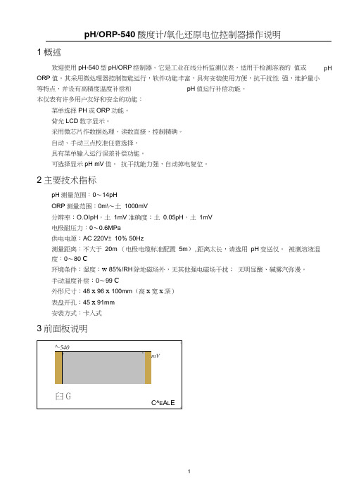
手动温度补偿:0〜99 C外形尺寸:48 x 96 x 100mm(高x宽x深)表盘开孔:45 x 91mm安装方式:卡入式3前面板说明液晶屏:用来显示pH值、mV值、量程上、下限值、错误标记等。
4后面板接线说明接线端子说明:(1)(2)⑶⑷(5)(6)(7)(8)暂时未用(9)(10)接市电AC 220V注意事项:(1)如仪器安装在较潮湿的环境,应加防潮措施。
(2)为保证安装操作安全,在安装完毕检查无误后再接通电源。
5测量电极安装(1)电极外形图保养: 1) 电极无需再注入电解质。
2) 电极避免干放,当电极不用时,要用水冲洗干净并插回加有 1molKCL/L 的盛液套内,或者将电极插入加有1molKCL/L 的容器中。
3)检查接头处是否干燥清洁,如有玷污,需用无水酒精擦洗干净吹干后使用。
4) 电极应定时清洗,若电极玻璃球泡与聚四氟乙烯环形液接界污染,可用下列试剂清 洗。
Mass Spectrometry Metabolite Library 盘5 产品说明书

MSMLS ™ Plate 5 (Water Soluble) Supplied by IROA Technologies, LLC.Catalog Number MSMLS05 Storage Temperature –20 ︒CProduct DescriptionMSMLS05 (Mass Spectrometry Metabolite LibraryPlate 5) is a collection of high quality small biochemical molecules that span a broad range of primarymetabolism. These are high purity (>95%) compounds supplied in an economical, ready-to-use format.The library is most commonly used to provide retention times and spectra for key metabolic compounds, help optimize analytical mass spectrometry protocols, and qualify and quantify mass spectrometry sensitivity and limit of detection.MSMLS ™ Plate 5 comes with MLSDiscovery ™, a software tool to support the extraction, manipulation, and storage of the data generated when using the MSMLS05. For further information on the software, to download, and for manual and video links please visit: /catalog/product/sigma/msmls05ComponentsMSMLS Plate 5 compounds are conveniently provided at 5 μg per well, enough for multiple injections, suitable for manual and automated workflow.The library is intended to be used for massspectrometry metabolomics applications and provides a broad representation of primary metabolism.Occasionally the plate map will change due to theavailability of compounds. The compounds of each row have distinct molecular masses and can be multiplexed, but users should refer to the plate map for their specific lot before proceeding.The plate map contains descriptors and represents information gathered from multiple databases. Please note this data may contain some errors. It is recommended for users to carefully review platecomposition and description information prior to use. To help build a better database, please report any observed discrepancies.MSMLS05 includes:∙ 1 polypropylene plate in 96 well formatPolypropylene deepwell (1.2 mL, total volume per well) plate (MasterBlock ®, GreinerNumber 780215) in combination with seals (VIEWseal ™, Greiner Number 676070)∙ 5 μg (dried weight) of each metaboliteMLSDiscovery software includes: ∙ Plate map∙ Alpha-numeric assigned position ∙ Descriptors:NameParent CIDKEGG ID where available or ChemSpider ID Molecular formula Molecular weightCAS Registry number ChEBIHMDB ID/YMDB IDPubChem Compound and Substance ID Metlin IDPrecautions and DisclaimerFor R&D use only. Not for drug, household, or other uses. Please consult the Safety Data Sheet for information regarding hazards and safe handling practices.Preparation InstructionsThe following are suggestions and dependent on user chromatography and instrumentation.Add 5% of final volume (up to 20 μL) of high purity methanol (MeOH) to every well of the plate. Addultrapure water to make up the desired volume. A final 5% methanol solution is suggested. Pipette liquid up and down in the well 2-3 times to facilitate solubilization.Pool compounds for multiplexing. Again, be sure to check the plate map to ensure one can adequately separate the compounds using the chromatographic system prior to pooling.2Storage/StabilityStore the plate at –20 ︒C.Once the metabolites are dissolved, the plate should be resealed and kept at –20 ︒C or –80 ︒C for long-term storage and protected from light. Avoid repeated freeze/thaw cycles.ProcedureThe compounds of MSMLS Plate 5 can either be used as standards and injected individually or mixed in such a way that the entire library may be examined with reasonable efficiency. Mixing compounds by row mixtures allows multiple compounds to be analyzed per injection. Be sure to check the plate map to ensure one can adequately separate the compounds using the chromatographic system prior to pooling.The following are only suggestions and depend on user chromatography and instrumentation.1. Individual InjectionsAs standards, each well represents a singlecompound. The entire library may be examined ingreat detail with several injections, one for each of the unique metabolites (Total volumes for each well of 250 μL–1 mL may be considered).2. Simple multiplex injectionsIf the rows of the plate are pooled, then the entirecollection may be analyzed with 8 injections ofsimple mixtures. Keep the total volume for eachwell to 150 μL or less to prevent loss due to dilution and use 5-10 μL of each well for the pooledsample. Then, inject 2, 4, or 6 μL of the pooledmaterial as needed. References1. Wishart, D.S. et al., HMDB: the HumanMetabolome Database. Nucleic Acids Res., 2007Jan; 35 (Database issue):D521-6. 17202168.2. Wishart, D.S. et al., HMDB: a knowledge base forthe human metabolome. Nucleic Acids Res., 200937 (Database issue):D603-610. 18953024.3. Wishart, D.S. et al., HMDB 3.0 — The HumanMetabolome Database in 2013. Nucleic Acids Res., 2013. Jan 1;41(D1):D801-7. 231616934. Hastings, J. et al., The ChEBI reference databaseand ontology for biologically relevant chemistry:enhancements for 2013. Nucleic Acids Res., 2013.5. Kanehisa, M., and Goto, S., "KEGG: KyotoEncyclopedia of Genes and Genomes". NucleicAcids Res., 2000 28 (1): 27– 30.doi:10.1093/nar/28.1.27. PMC 102409.PMID10592173.6. Tautenhahn, R. et al., An accelerated workflow foruntargeted metabolomics using the METLINdatabase. Nature Biotechnology, 2012 30: 826–828. doi:10.1038/nbt.2348.7. Smith, C.A. et al., METLIN: a metabolite massspectral database. The Drug Monit., 2005 27 (6):747–51. doi:10.1097/01.ftd.0000179845.53213.39.PMID 16404815.8. Bolton, E. et al., PubChem: Integrated Platform ofSmall Molecules and Biological Activities. Chapter12 IN Annual Reports in Computational Chemistry,Volume4, American Chemical Society, Washington, DC. 2008 Apr [free author manuscript]MSMLS and MLSDiscovery are trademarks of IROA Technologies, LLC.MasterBlock is a registered trademark and VIEWseal is a trademark of Greiner Bio-One GmbH.SS,AA,MAM 04/19-1©2019 Sigma-Aldrich Co. LLC. All rights reserved. SIGMA-ALDRICH is a trademark of Sigma-Aldrich Co. LLC, registered in the US and other countries. Sigma brand products are sold through Sigma-Aldrich, Inc. Purchaser must determine the suitability of the product(s) for their particular use. Additional terms and conditions may apply. Please see product information on the Sigma-Aldrich website at and/or on the reverse side of the invoice or packing slip.。
- 1、下载文档前请自行甄别文档内容的完整性,平台不提供额外的编辑、内容补充、找答案等附加服务。
- 2、"仅部分预览"的文档,不可在线预览部分如存在完整性等问题,可反馈申请退款(可完整预览的文档不适用该条件!)。
- 3、如文档侵犯您的权益,请联系客服反馈,我们会尽快为您处理(人工客服工作时间:9:00-18:30)。
rev. page date 1 of 2
08/2007
PART NUMBER: VFM05 series
DESCRIPTION: open frame AC/DC power supply
features ·universal input: 85~264VAC ·efficiency at 77% typical ·meets UL/cUL, TUV, CE ·conductive EMI meets CISPR/FCC, Class B ·single output
OUTPUT
hold up time short circuit protection temperature coefficient 8mS typ. @ 115VAC continERAL & SAFETY
operating temperature storage temperature approvals emmisions 0° - 70°C (see derating curve) -20° - +85°C UL60950, TUV, CE CISPR/FCC Class B
DESCRIPTION: open frame AC/DC power supply
DIMENSIONS (mm)
( ) Tolerances: .xx ± .02(.xx ± .5) unless otherwise noted.
-Vo
ACN
1.38 (35.00) 1.28 (32.48)
0.89 (22.50)
MECHANICAL OUTLINE
dimensions 2.17x1.38x0.83(max) inches (55x35x21mm 3 )
NOTES: 1. add a 0.1µF ceramic capacitor and a 10µF E.L. capacitor to output for ripple and noise measuring @20MHz BW. 2. line regulation is measured from 100VAC to 240VAC with full load. 3. load regulation is measured from 60% to 100% full load and from 60% to 20% full load (60% ±40% full load).
20050 SW 112th Ave. Tualatin, Oregon 97062 phone 503.612.2300 fax 503.612.2382
元器件交易网
rev. page date 2 of 2
08/2007
PART NUMBER: VFM05 series
ripple 1 (mVp-p) 50 mV 50 mV 90 mV 120 mV 180 mV 150 mV 240 mV
voltage accuracy ±1% ±1% ±1% ±1% ±1% ±1% ±1%
line reg. 2 ±0.5% ±0.5% ±0.5% ±0.5% ±0.5% ±0.5% ±0.5%
model number VFM05-S033 VFM05-S050 VMF05-S090 VFM05-S120 VFM05-S180 VFM05-S150 VFM05-S240
output voltage 3.3 V 5.0 V 9.0 V 12 V 18 V 15 V 24 V
output current min. rated max. 0A 1.25 A 0A 1.0 A 0A 0.55 A 0A 0.42 A 0A 0.28 A 0A 0.33 A 0A 0.23 A
DERATING CURVE
100% 75% 50% 25% 0% 0 10 20 30 40 50 60 70 80 90 Ambient Temperature(˚C) 20LFM(Natural Convection) -6.667%/˚C
20050 SW 112th Ave. Tualatin, Oregon 97062 phone 503.612.2300 fax 503.612.2382
ACL
+Vo
0.16 (4.01) 0.2 (5.01) 2.01 (51.01) 2.17 (55.00)
VR
0.49 (12.47) 0.83 (21.00)max 0.06 (1.60) 0.1 (2.60)
0.04 (1.02) 0.17 (4.40) 0.15 (3.70) 0.07 (1.78) 1.85 (47.00)
load reg. 3 ±1% ±1% ±1% ±1% ±1% ±1% ±1%
INPUT
voltage frequency inrush current isolation leakage current 85-264 Vac 47 to 63 Hz 40 A max. @ 264 Vac input to output = 4,242VDC 0.25mA max.
