2SD316EI_Manual
欧里森扫描手持无线电系统维护手册说明书
LBI-38903BMaintenance ManualORION™136-174 MHzSCAN AND SYSTEMMOBILE RADIOTABLE OF CONTENTSSynthesizer/Receiver/Exciter . . . . . . . LBI-38910Power Amplifier . . . . . . . . . . . . . . LBI-39002PA Interface . . . . . . . . . . . . . . . . LBI-38994 Control Logic/IF Board . . . . . . . . . . LBI-39003 Control Units . . . . . . . . . . . . . . . LBI-38992 Assemblies . . . . . . . . . . . . . . . . LBI-38909 Service Section . . . . . . . . . . . . . . LBI-38993ericssonz Ericsson Inc.Private Radio SystemsMountain View RoadLynchburg, Virginia 245021-800-528-7711 (outside USA, 804-528-7711)Printed in U.S.A.Copyright© October 1993 Ericsson GE Mobile Communications Inc.ContinuedSPECIFICATIONS*Frequency Range:136-153 MHz 150-174 MHzBattery Drain:ReceiverSquelched 1.1 Amperes at 13.8 V oltsUnsquelched 3.0 Amperes at 13.8 V olts (15 Watts Output)Transmitter25 Watts 12 Amperes at 13.2 V olts 50 Watts 14 Amperes at 13.6 V olts 110 Watts28 Amperes at 13.4 V oltsFrequency Stability:0.0002% depending on modelTemperature Range:-30° C (-22° F) to +60° C (+140° F)Duty Cycle:100% Receive, 14% Transmit TransmitterTransmit Output Power:25W/50W/110W Conducted Spurious:-85 dB Modulation:±5 kHzAudio Sensitivity:55 to 110 millivoltsAudio Frequency Characteristics:Within +1 dB to -3 dB of a 6 dB/octave pre-emphasis 300Hz and within +1 dB to -4.5 dB (+1 to -3 dB for Euro) of a 6 dB/octave pre-emphasis 3000 Hz per EIA standards.Post-limiter filter per FCC and EIA.Distortion:Less than 2% (1000 Hz)Deviation Symmetry:0.3 kHz maximum Maximum Frequency Separation:136-153 MHz, 17 MHz 150-174 MHz 24 MHz Microphone Load Impedance:600 OhmsPower Adjust Range:100% to 50% of rated power (U.S.A. Models)100% to 24% of rated power (Euro Models)RF Output Impedance:50 Ohms FM Noise:50 dBReceiverAudio Output:15 Watts with less than 3% distortion (To 4.0 ohm speaker)Sensitivity:0.35 µV (STD)12 dB SINAD (IEIA method)Selectivity:EIA Two-Signal Method (25 kHz Channels)95 dB (STD)This manual is published by Ericsson Inc., without any warranty. Improvements and changes to this manual necessitated by typographical errors, inaccuracies of current information, or improvements to programs and/or equipment, may be made by Ericsson Inc., at any time and without notice. Such changes will be incorportated into new editions of this manual. No part of this manual may be reproduced or transmitted in any form or by any means, electronic or mechanical, including photocopying and recording, for any purpose, without the express written permission of Ericsson Inc.LBI-389031DESCRIPTIONThe synthesized ORION mobile radio combinations are completely solid-state, utilizing microcomputer technology and integrated circuits to provide high-quality, high-reliability radios. Standard combinations may be equipped with:•Microcomputer Controlled Frequency Synthesizer•Up to 16 Channels•0.0002% Frequency Stability•Other Structured OptionsThe basic radio consists of three printed wiring boards mounted in a cast aluminum frame. The three boards are:1.The Control Logic/IF board,2.The Frequency Synthesizer/Receiver/Exciter board,3.The Power Amplifier board.The radio is of double-layer construction with tuning ad-justments easily accessible from the top of the radio.The Control Logic/IF Board located on the top of the ra-dio, while the Power Amplifier and the Synthesizer/Re-ceiver/Exciter boards are located on the bottom.SYNTHESIZER/INTERCONNECTThe synthesizer consists of a microcomputer, E lectricallyE rasable P rogrammable R ead O nly M emory (EEPROM), afrequency synthesizer IC, transmit and receive V oltage C on-trolled O scillator’s (VCO) and associated circuitry. The fre-quency synthesizer under control of the microcomputergenerates all transmit and receive R adio F requencies (RF).The EEPROM stores binary data for all radio frequen-cies, Channel Guard tones/digital codes and the timing func-tion of the C arrier C ontrol T imer (CCT). Themicrocomputer accesses the EEPROM and provides the cor-rect W ALSH bits to the Channel Guard circuitry to generatethe correct Channel Guard tone or digital code on a per-channel basis.PROGRAMMINGThe EEPROM allows the radio to be programmed or repro-grammed as needed to adapt to changing system requirements.Radio Frequencies, Channel Guard tone and digital codes andthe CCT function can be reprogrammed.The EEPROM can be reprogrammed through the radiofront connector using a personal computer. This programmerallows all information to be loaded simultaneously.Programming instructions are provided in the respectiveProgrammer Maintenance Manuals.TRANSMITTERThe transmitter consists of the exciter, frequency synthe-sizer, transmitter VCO and a P ower A mplifier (PA) assembly.The PA assembly consists of a PA board mounted on a heatsink assembly. The PA board also contains an antenna switch-ing diode and a low-pass filter.Audio and Channel Guard circuitry for the transmitter is lo-cated on the Logic Board.RECEIVERThe receiver consists of the frequency synthesizer, RXVCO, injection amplifiers, front end, IF and limiter detector.Audio, squelch and Channel Guard circuitry for the receiver islocated on the Logic Board.LOGIC FUNCTIONA microprocessor on the Control Logic/IF board controlsthe frequency synthesizer, the TX ON/OFF, the decoding ofCTCSS tones, the generation of CTCSS tones,... etc. The audioprocessor circuitry of the transmitter and the receiver are lo-cated on the Control Logic/IF Board. Squelch circuitry and aconnection to the digital AEGIS circuit is also located on theControl Logic/IF Board.OPERATIONComplete operating instructions for the ORION Two-WayRadio are provided in Operator’s Manual LBI-38888 for thecontrol unit used.MAINTENANCEThe Service Section in maintenance manual LBI-38993contains the maintenance information to service this radio. TheService Section includes:•Dissassembly Procedures•Replacement of IC’s, chip capacitors and resistors•Alignment procedures for the transmitter and receiver•Troubleshooting Procedures and wave formsFigure 1 - ORION Mobile RadioSPECIFICATIONS* - Cont.Receiver - Cont.Spurious Response:-100 dB (STD)Intermodulation 30 kHz:-85 dB (STD)Maximum Frequency Separation:136-153 MHz .... 17 MHz150-174 MHz .... 24 MHzFrequency Response:Within +1, -3 dB of 6 dB/octave de-emphasis from 300 to3000 MHz (1000 Hz reference)RF Input Impedance:50 OhmsHum/Noise ratio:Unsquelched-50 dBSquelched-70 dBChannel Spacing:30 kHzREGULATORY APPROV ALSThe following equipment authorized numbers have been granted:COUNTRY REGULATORY APPROV ALUNITED STATES FCC AXATR - 312-A2/B2 (30/50W)AXATR - 313-A2/B2 (110W)CANADA DOC TR - 312-A2/B2 (30/50W)TR - 313-A2/B2 (110W)*These specifications are intended primarily for use of the service technician. Refer to the appropriate Specifications Sheet for the complete specifications.LBI-389032SYSTEM INTERCONNECTION DIAGRAMLBI-38903 Array U.S.A. LOW POWER3LBI-38903SYSTEM INTERCONNECTION DIAGRAMU.S.A. HIGH POWER4SYSTEM INTERCONNECTION DIAGRAMLBI-38903EUROPEAN5。
2SD1803 PDF规格书
Unit: mm
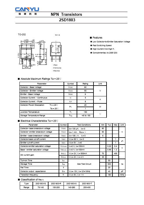
■ Features
● Low Collector-to-Emitter Saturation Voltage ● Fast Switching Speed ● High Current And High fT. ● Complementary to 2SB1203
+0 2.65 .25 -0.1
1000 7 5 3 2
100 7 5 3 2
hFE -I c Ta=75 C
C VCE=2V
Ta=25 C
Ta=-25 C
10 5 7 0.01 2 3 5 7 0.1 2 3 5 71.0 2 3 5 7 10
Collector Current, IC (A)
NPN Transistors 2SD1803
pF
180
MHz
NPN Transistors 2SD1803
TEST CIRCUIT
IB1
INPUT
RB
OUTPUT
IB2
RL
50
VR
PW=20μS Duty Cycle≦1%
Ic=10IB1=-10IB2=2A
+ 100μ
-5V
+ 470μ
25V
(Unit : (resistance : Ω, capacitance : F))
Parameter
Symbol
Test Conditions
Collector- base breakdown voltage
VCBO Ic= 100 μA, IE= 0
Collector- emitter breakdown voltage
VCEO Ic= 1 mA, RBE= ∞
德威尔智能实验室设备有限公司产品介绍说明书

VISIT OUR WEBSITES: • • .auElectric and Pneumatic ActuatorsSeries ABV incorporates a full port brass ball valve for great flow rates with minimal pressure drop. The valve features a blowout proof stem for added safety, reinforced PTFE seats and seals for longer life, and a chrome/nickel plated ball for better performance.Actuators are direct mounted creating a compact assembly for tight spaces. Double o-ring stem seals assure leak free operation.The ABV Series is an economical automated valve package with either an electric or pneumatic actuator. Electric actuated models are weatherproof, NEMA 4, powered by standard 115VAC supply, and are available in either two-position or proportional control. Two-position actuators use the 115 VAC input to drive the valve open or closed, while the modulating actuator accepts a 4 to 20 mA input for infinite valve positioning. Actuator features thermal overload protection and a permanently lubricated gear train.The pneumatic double acting actuator uses an air supply to drive the valve open and closed.The actuator has two supply ports with one driving the valve open and the other driving the valve closed. Spring return pneumatic actuator uses the air supply to open the valve and internally loaded springs return the valve to the closed position. Also available is the SV3solenoid valve to electrically switch the air supply pressure between the air supply ports for opening and closing the valve. Actuators are constructed of anodized and epoxy coated aluminum for years of corrosion free service.FEATURES• Full port brass ball valve• Direct mount actuators for compact assembly• Electric actuator that is rated NEMA 4 and is available in two position or modulating • Pneumatic double acting or spring return rack and pinion actuatorCBA DEFSPECIFICATION Body:2 – piece.Line Size:1/4˝ to 4˝.End Connections:Female NPT.Pressure Limit:600 psi (41 bar) WOG,100 psi (6.9 bar) SWP .Wetted Materials:Body, end cap, stem:Brass; Ball: Chrome/nickel plated brass;Seat, stem seal: PTFE.Temperature Limit:300°F (148°C).Other Materials:Body seal, body O-ring, stem O-ring: Fluoroelastomer. ACTUATORS ElectricPower Requirements:115 VAC, 50/60HZ, single phase. Optional 220 VAC, 24VAC, 12 VDC, and 24 VDC.Power Consumption (Locked Rotor Current):Two position: U11: 0.55A; U12,U13, U14: 0.75A; U15: 1.1A; Modulating:V12, V13, V14: 0.75A; V15: 1.1A. Cycle Time (per 90°):Two position: U11: 2.5 sec.; U12, U13: 5 sec.; U14: 10sec.; U15: 15 sec. Modulating: V12, V13:10 sec.; V13: 20 sec.; V15: 30 sec.Duty Cycle:Two position: U11: 75%;U12, U13, U14, U15: 25%. Modulating:V12, V13, V14, V15: 75%.Enclosure Rating:NEMA 4. Optional NEMA 7.Housing Material:Aluminum withthermal bonding polyester powder finish.Temperature Limit:0 to 150°F (-17 to 65°C).Electrical Connection:1/2˝ female NPT.Modulating Input:4 to 20 mA.Standard Features:Manual override and position indicator except modulating units.Pneumatic “DA” and “SR” SeriesType:DA Series is double acting and SR Series is spring return (rack and pinion).Normal Supply Pressure:80 psi (5.5 bar).Maximum Supply Pressure:130 psig (9.0 bar).Air Connections:DA/SR1 to 5: 1/8˝female NPT, all other sizes: 1/4˝ female NPT.Air Consumption (per stroke):DA1: 2.32 cu. in.; DA2, SR2: 9.34 cu. in.;DA3, SR3: 17.21 cu. in.; DA5, SR5:39.54 cu. in.; SR6: 54.37 cu. in.Cycle Time (per 90°):DA1: .03 sec.;DA2: .05 sec.; DA3: .06 sec.; DA5: .18sec.; SR2: .09 sec.; SR3: .13 sec.; SR5:.28 sec.; SR6: .39 sec.Housing Material:Anodized aluminum body and epoxy coated aluminum end caps.Temperature Limit:-4 to 180°F (-20 to 85°C).Accessory Mounting:NAMUR standard.Standard Features: Position indicator.E CBADNote: All spring return actuators are factory standard as spring (fail) close.。
唯能采样器-附加设备-非返回阀-手册说明书

1 Safety
Unsafe practices and other important information are emphasised in this manual. Warnings are emphasised by means of special signs.
1.1 Important information
Instruction Manual
Unique Sampling Valve - Accessories 84
ESE02425-EN1
Original manual
2013-04
Table of contents
The information herein is correct at the time of issue but may be subject to change without prior notice
3. Operation ............................................................................................... 8 3.1. Operation .......................................................................................... 8 3.2. Troubleshooting ................................................................................... 8 3.3. Recommended cleaning ......................................................................... 9
辛德勒电子October 2019控制和信号单元目录说明书

Catalog | October 2019Control and signaling units Ø 22®XB4 metal,Find your catalog>With just 3 clicks, you can reach the Industrial Automationand Control catalogs, in both English and French >Download Digi-Cat with this linkSelect your training>Find the right Training for your needs on our Global website >Locate the training center with the selector tool, using this linkQuick access to product informationGet technical information about your product•Updated quarterly•Embeds product selectors and configurators,360° images, training centers•Optimized search by commercial referenceEach commercial reference presented in a catalog contains a hyperlink. Click on it to obtain the technical information of the product:–Characteristics, Dimensions and drawings, Mounting and clearance,Connections and schemas, Performance curves–Product image, Instruction sheet, User guide, Product certifications,End of life manualGeneral contentsHarmony® XB4 metal for explosive atmospheresb Presentation .............................................................................................page 2b ReferencesFor ATEX dust offerv Spring return pushbuttons, unmarked-Illuminated and non illuminated .............................................................page 4v Mushroom head pushbuttons, spring return ...............................................page 5v Emergency stop and Emergency switching off functions ............................page 5v Selector switches with standard and long handle ........................................page 6v Key switches ...............................................................................................page 6v Pilot lights with integral LED ........................................................................page 7For Explosive atmosphere dust + gas offerv Spring return pushbuttons, unmarked-Illuminated and non illuminated .............................................................page 8v Mushroom head pushbuttons, spring return ...............................................page 9v Emergency stop and Emergency switching off functions ............................page 9v Selector switches with standard and long handle ......................................page 10v Key switches .............................................................................................page 10v Pilot lights with integral LED .......................................................................page 11v Push-to-test pilot light ................................................................................page 11v Contact and Light blocks ............................................................................page 11b Product reference index .........................................................................page 12References:Example of hazardous dust zoneZone 20Zone 21Zone 22Example of hazardous gas and vapor zoneZone 2Zone 0Zone 1PresentationThe Harmony ® XB4 Explosive atmosphere range of modular control and signaling units are designed for industries where explosive atmospheres can be present. This range is ideal for use in environments where the generation of possible ignition sources can be prevented and controlled.This range includes 2 offers that meet the different standards:b ATEX dust offer: compliant with European Directive 2014/34/EU , Zone 21/22 b Explosive atmosphere dust + gas offer: IECex Zone 1/2/21/22; UL 60079 Zone 1/ 2/21/22; NEC 500 Class 1 Div 2, Class 2 Div 2 & Class 3This range offers products for the following functionsb ATEX dust offer: illuminated and non-illuminated pushbuttons, selector and key switches, Emergency stop functions, and pilot lights.b Explosive atmosphere dust + gas offer: illuminated and non-illuminated pushbuttons, selector and key switches, Emergency stop functions, pilot lights, push-to-test pilot lights, contact and LED light blocks.Explosive atmosphere and ignition sourcesAccording to the directives, a potentially explosive atmosphere is the mixture of air with flammable substances in the form of gas, vapor, and/or dust, that whenexposed to an ignition source under normal atmospheric conditions can completely or partially catch fire and explode.The types of ignition sources that can create an explosive atmosphere are: b Hot surfaces b Flames and hot gases b Mechanically produced sparks b Electrical equipment b Transient currents b Static electricity b Lightning strikes b Electromagnetic waves b Optical radiation b Ultrasound b Chemical reactions b People (indirectly)Explosive atmospheres are found in areas like: b Metal surface grinding, especially aluminum dust and particles b Oil refineries, rigs and processing plants b Gas pipelines and distribution centers b Printing industries, paper and textiles b Aircraft refueling and hangars b Chemical processing plants b Grain handling and storage b Sewage treatment plants b Surface coating industries b Underground coal mines b Wood working areas b Sugar refineriesb Vessels/shipsb Power plantsExplosive atmosphere IECEx zones and NEC 500 class and divisionsv Food & Beveragev Oil & Gas, including petrochemical extraction & transformation, car gas stations and gas bottling plants v Chemicals v Printingv Paint manufacturing linesFor more technical information, please refer to the Harmony XB4 Explosive atmosphere products page on the Schneider Electric website.Food & Beverage Oil & GasPrinting Paint manufacturingXB4BP383B5EXX B 4E X _1038_C P O D A 2016003XB4BP482EXP F 152007BEmergency stop and Emergency switching off functionsXB4BC21EX101162XB4BS9445EX110018Presentation:Key switchesPresentation: XB4BD33EX107762XB4BJ33EXP F 106190XB4BG33EXP F 106189(50/60 Hz)Green XB4BVBG3EX 0.080/0.176Red XB4BVBG4EX 0.080/0.176Orange XB4BVBG5EX 0.080/0.176BlueXB4BVBG6EX 0.080/0.176110...120 a (50/60 Hz)21-22–White XB4BVG1EX 0.080/0.176Green XB4BVG3EX 0.080/0.176Red XB4BVG4EX 0.080/0.176Orange XB4BVG5EX 0.080/0.176BlueXB4BVG6EX 0.080/0.176230...240 a (50/60 Hz)21-22–White XB4BVM1EX 0.080/0.176Green XB4BVM3EX 0.080/0.176Red XB4BVM4EX 0.080/0.176Orange XB4BVM5EX 0.080/0.176BlueXB4BVM6EX0.080/0.176(1) For additional contacts, please use standard Harmony XB4 range contact blocks ZBE101(1 NO) and ZBE102 (1 NC)XB4BVB6EX110022Control and signaling units Ø 22Harmony XB4 metal, explosive atmosphere Explosive atmosphere dust + gas offerSpring return pushbuttons, unmarkedReferencesPresentation: XB4BP482GEXX B 4E X _1038_C P S C T 17017XB4BP583BM5GEXX B 4E X _1038_C P S C T 17023Control and signaling units Ø 22Harmony XB4 metal, explosive atmosphere Explosive atmosphere dust + gas offerMushroom head pushbuttons, spring returnEmergency stop and Emergency switching off functionsReferencesXB4BC21GEX101162XB4BS9445GEXX B 4E X _1038_C P S C T 17032XB4BS8445GEX XB4BS8444GEXX B 4E X _1038_C P S C T 17031Key switchesPresentation: XB4BD33GEXX B 4E X _1038_C P S C T 17008XB4BJ33GEXX B 4E X _1038_C P S C T 17013XB4BG33GEX X B 4E X _1038_C P S C T 17011Contact and Light blocksXB4BVBM6GEXX B 4E X _1038_C P S C T 17038XB4BW25BM5GEXX B 4E X _1038_C P S C T 17088ZBE101GEXX B 4E X _1038_C P S C T 17039ZBVBM3GEXX B 4E X _1038_C P S C T 17041Product reference index IndexXB4BC21EX5 XB4BC21GEX9 XB4BC31EX5 XB4BC31GEX9 XB4BC42EX5 XB4BC42GEX9 XB4BC51EX5 XB4BC51GEX9 XB4BC61EX5 XB4BC61GEX9 XB4BD25EX6 XB4BD25GEX10 XB4BD33EX6 XB4BD33GEX10 XB4BD53EX6 XB4BD53GEX10 XB4BG03EX6 XB4BG03GEX10 XB4BG21EX6 XB4BG21GEX10 XB4BG33EX6 XB4BG33GEX10 XB4BG41EX6 XB4BG41GEX10 XB4BG61EX6 XB4BG61GEX10 XB4BJ21EX6 XB4BJ21GEX10 XB4BJ33EX6 XB4BJ33GEX10 XB4BJ53EX6 XB4BJ53GEX10 XB4BP21EX4 XB4BP21GEX8 XB4BP31EX4 XB4BP31GEX8 XB4BP42EX4 XB4BP42GEX8 XB4BP51EX4 XB4BP51GEX8 XB4BP61EX4 XB4BP61GEX8 XB4BP181EX4 XB4BP181GEX8 XB4BP183B5EX4 XB4BP183BG5EX4 XB4BP183BM5GEX8 XB4BP183G5EX4 XB4BP183M5EX4 XB4BP381EX4 XB4BP381GEX8 XB4BP383B5EX4 XB4BP383BG5EX4 XB4BP383BM5GEX8 XB4BP383G5EX4 XB4BP383M5EX4 XB4BP482EX4 XB4BP482GEX8 XB4BP483B5EX4 XB4BP483BG5EX4 XB4BP483BM5GEX8 XB4BP483G5EX4XB4BP483M5EX4XB4BP581EX4XB4BP581GEX8XB4BP583B5EX4XB4BP583BG5EX4XB4BP583BM5GEX8XB4BP583G5EX4XB4BP583M5EX4XB4BP681EX4XB4BP681GEX8XB4BP683B5EX4XB4BP683BG5EX4XB4BP683BM5GEX8XB4BP683G5EX4XB4BP683M5EX4XB4BPS11EX4XB4BPS11GEX8XB4BPS21EX4XB4BPS21GEX8XB4BPS31EX4XB4BPS31GEX8XB4BPS42EX4XB4BPS42GEX8XB4BPS51EX4XB4BPS51GEX8XB4BPS61EX4XB4BPS61GEX8XB4BS8444GEX9XB4BS8445EX5XB4BS8445GEX9XB4BS9445EX5XB4BS9445GEX9XB4BT845EX5XB4BT845GEX9XB4BVB1EX7XB4BVB3EX7XB4BVB4EX7XB4BVB5EX7XB4BVB6EX7XB4BVBG1EX7XB4BVBG3EX7XB4BVBG4EX7XB4BVBG5EX7XB4BVBG6EX7XB4BVBM1GEX11XB4BVBM3GEX11XB4BVBM4GEX11XB4BVBM5GEX11XB4BVBM6GEX11XB4BVG1EX7XB4BVG3EX7XB4BVG4EX7XB4BVG5EX7XB4BVG6EX7XB4BVM1EX7XB4BVM3EX7XB4BVM4EX7XB4BVM5EX7XB4BVM6EX7XB4BW21BM5GEX11XB4BW23BM5GEX11XB4BW24BM5GEX11XB4BW25BM5GEX11XB4BW26BM5GEX11ZBE101GEX11ZBE102GEX11ZBVBM1GEX11ZBVBM3GEX11The information provided in this documentation contains general descriptions and/or technical characteristics of the performance of the products contained herein. This documentation is not intended as a substitute for and is not to be used for determining suitability or reliability of these products for specific user applications. It is the duty of any such user or integrator to perform the appropriate and complete risk analysis, evaluation and testing of the products with respect to the relevant specific application or use thereof. Neither Schneider Electric nor any of its affiliates or subsidiaries shall be responsible or liable for misuse of the information contained herein.Design: Schneider ElectricPhotos: Schneider ElectricSchneider Electric Industries SASHead Office35, rue Joseph Monier - CS 30323F-92500 Rueil-Malmaison CedexFranceDIA5ED2170903ENOctober 2019 - V2.0。
HP 32f 模型 L63916 维护和服务指南说明书

2SD1621 PDF规格书

■ Electrical Characteristics Ta = 25℃
Parameter Collector- base breakdown voltage Collector- emitter breakdown voltage Emitter - base breakdown voltage Collector-base cut-off current Emitter cut-off current Collector-emitter saturation voltage Base - emitter saturation voltage DC current gain Turn-on time Storage time Turn-off time Collector output capacitance Transition frequency Symbol VCBO VCEO VEBO ICBO IEBO VCE(sat) VBE(sat) hFE ton tstg toff Cob fT VCB= 10V, IE= 0,f=1MHz VCE= 10V, IC= 50mA See specified Test Circuit. Test Conditions Ic= 100 μA, IE= 0 Ic= 1 mA, RBE= ∞ IE= 100μA, IC= 0 VCB= 20V , IE= 0 VEB= 4V , IC=0 IC=1.5A, IB=75mA IC=1.5A, IB=75mA VCE= 2V, IC= 100mA VCE= 2V, IC= 1.5A 100 65 60 500 25 19 150 pF MHz ns 0.18 0.85 Min 30 25 6 0.1 0.1 0.4 1.2 560 uA V V Typ Max Unit
艾瑟顿198931产品说明书

Eaton 198931Eaton Moeller® series Rapid Link - Speed controllers, 8.5 A, 4 kW, Sensor input 4, Actuator output 2, 400/480 V AC, Ethernet IP, HAN Q4/2, with manual override switch, with braking resistance, STO (Safe Torque Off), with fanGeneral specificationsEaton Moeller® series Rapid Link Speed controller198931195 mm270 mm 220 mm 3.81 kgCEIEC/EN 61800-5-1 UL approval UL 61800-5-1 RoHSRASP5-8424EIP-412R111S1Product NameCatalog NumberProduct Length/Depth Product Height Product Width Product Weight Certifications Catalog Notes Model Code3 fixed speeds and 1 potentiometer speedcan be switched over from U/f to (vector) speed control Connection ofInternal and on heat sink, temperature-controlled Fan Parameterization: KeypadParameterization: FieldbusParameterization: drivesConnect mobile (App) Parameterization: drivesConnectSelector switch (Positions: REV - OFF - FWD)Control unitManual override switchKey switch position OFF/RESETKey switch position HANDThermo-click with safe isolationFanBreaking resistanceTwo sensor inputs through M12 sockets (max. 150 mA) for quick stop and interlocked manual operation2 Actuator outputsInternal DC linkPC connectionKey switch position AUTOIGBT inverterBraking resistancePTC thermistor monitoring4-quadrant operation possibleFor actuation of motors with mechanical brakeBrake chopper with braking resistance for dynamic braking1 potentiometer speedSTO (Safe Torque Off)3 fixed speeds IP65NEMA 121st and 2nd environments (according to EN 61800-3)IIISpeed controllerEtherNet/IPC2, C3: depending on the motor cable length, the connected load, and ambient conditions. External radio interference suppression filters (optional) may be necessary.C1: for conducted emissions only2000 VAC voltageCenter-point earthed star network (TN-S network)Phase-earthed AC supply systems are not permitted.Vertical15 g, Mechanical, According to IEC/EN 60068-2-27, 11 ms, Half-sinusoidal shock 11 ms, 1000 shocks per shaftResistance: 10 - 150 Hz, Oscillation frequencyResistance: 57 Hz, Amplitude transition frequency on accelerationResistance: 6 Hz, Amplitude 0.15 mmResistance: According to IEC/EN 60068-2-6Features Fitted with:FunctionsDegree of protectionElectromagnetic compatibilityOvervoltage categoryProduct categoryProtocolRadio interference classRated impulse withstand voltage (Uimp)System configuration typeMounting positionShock resistanceVibrationsupply voltagevia adaptercable on roundor flexiblebusbar junctionDiagnostics andreset on thedevice and viaEthernet IPintegrated PTCthermistormonitoring andThermoclick withsafe isolationoptional: 4sensor inputswith M12-Yadapter forswitchover tocreep speedoptional: Fasterstop if external24 V failsTwo sensorinputs throughM12 sockets(max. 150 mA)for quick stopand interlockedmanualoperationwith AUTO -OFF/RESET -HAND keyswitcheswith selectorswitch REV -OFF - FWDAbove 1000 m with 1 % performance reduction per 100 m Max. 2000 m-10 °C40 °C-40 °C70 °CIn accordance with IEC/EN 50178< 95 %, no condensation Adjustable, motor, main circuit0.8 - 8.5 A, motor, main circuit< 10 ms, Off-delay< 10 ms, On-delay98 % (η)7.8 A3.5 mA120 %Maximum of one time every 60 seconds 380 V480 V380 - 480 V (-10 %/+10 %, at 50/60 Hz)PM and LSPM motorsSensorless vector control (SLV) Synchronous reluctance motorsU/f controlBLDC motors0 Hz500 HzAt 40 °CFor 60 s every 600 s12.7 AAltitudeAmbient operating temperature - min Ambient operating temperature - max Ambient storage temperature - min Ambient storage temperature - max Climatic proofing Current limitationDelay timeEfficiencyInput current ILN at 150% overload Leakage current at ground IPE - max Mains current distortionMains switch-on frequencyMains voltage - minMains voltage - maxMains voltage toleranceOperating modeOutput frequency - minOutput frequency - maxOverload currentOverload current IL at 150% overload45 Hz66 Hz8.5 A at 150% overload (at an operating frequency of 8 kHz and an ambient air temperature of +40 °C)4 kW400 V AC, 3-phase480 V AC, 3-phase0.1 Hz (Frequency resolution, setpoint value)200 %, IH, max. starting current (High Overload), For 2 seconds every 20 seconds, Power section50/60 Hz8 kHz, 4 - 32 kHz adjustable, fPWM, Power section, Main circuitAC voltageCenter-point earthed star network (TN-S network)Phase-earthed AC supply systems are not permitted.5 HP≤ 0.6 A (max. 6 A for 120 ms), Actuator for external motor brakeAdjustable to 100 % (I/Ie), DC - Main circuit≤ 30 % (I/Ie)400/480 V AC -15 % / +10 %, Actuator for external motor brake765 VDC10 kAType 1 coordination via the power bus' feeder unit, Main circuit24 V DC (-15 %/+20 %, external via AS-Interface® plug)400/480 V AC (external brake 50/60 Hz)Ethernet IP, built inPlug type: HAN Q4/2 Specification: S-7.4 (AS-Interface®) C1 ≤ 1 m, maximum motor cable length C3 ≤ 25 m, maximum motor cable length C2 ≤ 5 m, maximum motor cable lengthRated frequency - minRated frequency - maxRated operational current (Ie)Rated operational power at 380/400 V, 50 Hz, 3-phase Rated operational voltageResolutionStarting current - maxSupply frequencySwitching frequencySystem configuration type Assigned motor power at 460/480 V, 60 Hz, 3-phase Braking currentBraking torqueBraking voltageSwitch-on threshold for the braking transistorRated conditional short-circuit current (Iq)Short-circuit protection (external output circuits) Rated control voltage (Uc)Communication interfaceConnectionInterfacesCable lengthNumber of slave addresses: 31 (AS-Interface®)Max. total power consumption from AS-Interface® power supply unit (30 V): 250 mAMeets the product standard's requirements.Meets the product standard's requirements.Meets the product standard's requirements.Meets the product standard's requirements.Meets the product standard's requirements.Does not apply, since the entire switchgear needs to be evaluated.Does not apply, since the entire switchgear needs to be evaluated.Meets the product standard's requirements.Does not apply, since the entire switchgear needs to be evaluated.Meets the product standard's requirements.Does not apply, since the entire switchgear needs to be evaluated.Does not apply, since the entire switchgear needs to be evaluated.Is the panel builder's responsibility.Is the panel builder's responsibility.Is the panel builder's responsibility.Is the panel builder's responsibility.10.2.2 Corrosion resistance10.2.3.1 Verification of thermal stability of enclosures 10.2.3.2 Verification of resistance of insulating materials to normal heat10.2.3.3 Resist. of insul. mat. to abnormal heat/fire by internal elect. effects10.2.4 Resistance to ultra-violet (UV) radiation 10.2.5 Lifting10.2.6 Mechanical impact10.2.7 Inscriptions10.3 Degree of protection of assemblies10.4 Clearances and creepage distances 10.5 Protection against electric shock10.6 Incorporation of switching devices and components 10.7 Internal electrical circuits and connections 10.8 Connections for external conductors 10.9.2 Power-frequency electric strength 10.9.3 Impulse withstand voltageIs the panel builder's responsibility.The panel builder is responsible for the temperature rise calculation. Eaton will provide heat dissipation data for the devices.Is the panel builder's responsibility. The specifications for the switchgear must be observed.Is the panel builder's responsibility. The specifications for the switchgear must be observed.The device meets the requirements, provided the information in the instruction leaflet (IL) is observed.Generation change from RA-MO to RAMO 4.0Generation Change RA-SP to RASP5Generation change RAMO4 to RAMO5Configuration to Rockwell PLC for Rapid LinkGeneration Change RASP4 to RASP5Generation change from RA-SP to RASP 4.0Rapid Link 5 - brochureDA-SW-drivesConnect - installation helpDA-SW-USB Driver PC Cable DX-CBL-PC-1M5DA-SW-Driver DX-CBL-PC-3M0DA-SW-drivesConnect - InstallationshilfeDA-SW-drivesConnectDA-SW-USB Driver DX-COM-STICK3-KITMaterial handling applications - airports, warehouses and intra-logistics ETN.RASP5-8424EIP-412R111S1.edzIL034093ZUrasp5_v34.stpramo5_v34.dwgDA-DC-00004184.pdfDA-DC-00003964.pdfDA-DC-00004613.pdfDA-DC-00004612.pdfeaton-bus-adapter-rapidlink-speed-controller-dimensions-005.eps eaton-bus-adapter-rapidlink-speed-controller-dimensions-002.eps eaton-bus-adapter-rapidlink-speed-controller-dimensions-004.eps eaton-bus-adapter-rapidlink-speed-controller-dimensions-003.eps10.9.4 Testing of enclosures made of insulating material10.10 Temperature rise10.11 Short-circuit rating10.12 Electromagnetic compatibility 10.13 Mechanical function Applikasjonsmerknader BrosjyrereCAD model Installeringsinstruksjoner mCAD model SertifiseringsrapporterTegningerEaton Corporation plc Eaton House30 Pembroke Road Dublin 4, Ireland © 2023 Eaton. Med enerett. Eaton is a registered trademark.All other trademarks areproperty of their respectiveowners./socialmedia。
EM316WERMT-S2中文资料(MRV Communications)中文数据手册「EasyDatasheet - 矽搜」

NA/22 (@1310 nm)
1-100 m/ 0-45 km
NA/32 (@1550 nm)
1-100 m/ 30-130 kmห้องสมุดไป่ตู้
芯片中文手册,看全文,戳
媒体转换器 中继器和优化器
EM316ERM
双纤
订购信息
Model
功能
EM316ERM/M
10Base-T Ethernet Copper to Multi-mode, Dual Fiber with IP-Less™ Remote Management.
RJ-45/SC
RJ-45/SC
波长( nm) 端口 /链路
NA/1310, 1550 NA/1310, 1550 NA/1550, 1590
NA/1550, 1310
NA/1550, 1310
NA/1590, 1550
¹ Default connectors listed, others optional. ² Higher budgets available. ³ Distances are approximate and assume 9µ SM and 62.5µ MM. 125Mbps
EM316ERM/MX
10Base-T Ethernet Copper to Extended Multi-mode, Dual Fiber with IP-Less™ Remote
Management.
EM316ERM/S1
10Base-T Ethernet Copper to Single-mode, Dual Fiber with IP-Less™ Remote Management.
检测允许使用是直连或交叉电缆
2SD2568中文资料(rohm)中文数据手册「EasyDatasheet - 矽搜」
0.5 (A)
1
0.5 (A)
1
0.02 BASE SATURATION VOLTAGE : V 0.01 0.001 0.002 0.005 0.01 0.02 0.05 0.1 0.2 COLLECTOR CURRENT : I
C
0.5 (A)
1
COLLECTOR CURRENT : I
图4 DC电流增益 - 集电极电流(
1/2
芯片中文手册,看全文,戳
2SD2568
晶体管电气特Biblioteka 曲线200 (mA) 160
C
Ta=25 C
mA 3.0m A 2.5m A 2.0m A 1.5m A
1 (A)
C
V CE =3V
FE
1000 500 200 100
Ta=25 C
0.5 0.2 0.1 0.05
25°C
FE
2SD2568 CPT3 PQ TL 2500
电气特性
Parameter Collector-base breakdown voltage Collector-emitter breakdown voltage Emitter-base breakdown voltage Collector cutoff current Emitter cutoff current Collector-emitter saturation voltage Base-emitter saturation voltage DC current transfer ratio Transition frequency Output capacitance
(V) 2
BE(sat)
200 100 50 20
雷维顿Decora壁栅式PIR人员检测自适应技术电源开关说明书

M D S 15Decora ® Wall Switch PIR Lev-Lok ® Occupancy Sensor with Self-Adaptive TechnologyBASIC OPERATIONThe Leviton Decora ® Wall Switch Passive Infrared (PIR) Lev-Lok ® Occupancy Sensor (MDS15) uses PIR detec tion technology to monitor a room for occupancy through asegmented Fresnel lens. This specialized lens divides the field-of-view into sensor zones. When a person passes into or out of a sensor zone, the sensor detects motion and switches the lights ON. The lights will remain ON as long as there is an occupant moving through the sensor zones.A delayed-OFF time adjustment prevents the lights from switching OFF when the space is occupied. In order to keep the lights ON, a person must pass through a sensor zone atleast once during the selected delayed-OFF time interval. An LED indicator blinks each time the unit detects activity in the sensor zones. When the space being monitored by the sensor isunoccupied for the length of time chosen as the delayed-OFF interval, the unit will beep 3 times. Ten seconds after the last warning beep, the unit will switch the lights OFF.LEV-LOK TECHNOLOGYLev-Lok’s innovative design streamlinesinstallation and reduces costs. In just two easy steps, the wiring device is securely attached to the wiring module.Place the wiring module over the device’s connection pins and twist clockwise tolock. Replacement is just as easy—just turn counter-clockwise to unlock and remove. The module is keyed so that it cannot be installed incorrectly. This not only saves time during the initial installation, but makes maintenance applications quicker, safer and easier as well.APPLICATIONSThe MDS15 is used to provide automatic lighting control for energy savings and convenience in a variety of commercial applications, including:• Small offices• Heavier loads • Private restrooms • Lounges • Storage areas • Classrooms• Conference roomsThe MDS15 can be used for automatic switching of incandescent lamps and low-voltage lighting with electronic and magnetic ballasts. The unit also features a manual override switch that can be used to keep lights OFF while an area is occupied, which may be desired in conference rooms and other areas during slide or film presentations. The unit installs in place of asingle-pole wall switch and fits in a standard wallbox. The unit requires a ground connection.MDS15Leviton Manufacturing Co., Inc. Global Headquarters201 North Service Road, Melville, NY 11747-3138 tech line 800-824-3005 fax 800-832-9538©2017 Leviton Manufacturing Co., Inc. All rights reserved. Subject to change without notice.PRODUCT DATA15FEATURES• Fits in standard wallbox and replaces single-pole wall switch; ground connection required. Gangable with other units• Low-profile design eliminates obtrusive“scanning-device” look. Elegant Decora wallplates compliment any interior for sleek aesthetics; uses Decora wallplates and coordinates with Leviton’s popular line of Decora wiring devices• 180° field-of-view provides approximately 2,100 square feet of coverage suitable for small offices, conference rooms, class rooms, stock rooms, lounges, private restrooms and a variety of commercial areas• Convenient pushbutton provides manual-ON/OFF light switching at any time• Two dual element PIR sensors used to widen detection range• Segmented Fresnel lens provides optimum sensitivity and performance. Designed with an extensive “minor motion” area where even slight body movements will be detected • Vandal resistant PIR lens• Lev-Lok makes installation and replacement simple with latch-and-lock system which streamlines installation and reduces costs• The Lev-Lok wiring module is keyed so that itcannot be installed incorrectly, saving time during installation and making maintenance quicker, safer and easier• Blinders—horizontal field-of-view may be adjusted between 180° and 60° of arc by using integral blinders located on either side of the lens. No masking tape required• Manual-ON/auto-OFF mode for installations where manual ON switching is required but auto-OFF switching is still desired• Red LED indicator light flashes when PIR sensor detects motion to verify detection is active• Time Delay—in adapting mode, the time delay can be configured from 30s (test mode), 5, 10 and 20 minutes. In non-adapting mode, the delay can be configured from 5, 10, 20 and 30 minutes• Light sensor adjustable Ambient Light Override ranges from approximately 2FC (20LUX) to 500+FC (5,000+LUX) to prevent lights from turning ON automatically during periods of ample natural light, increasing energy savings• Light sensor enables the load hold-OFF feature once level has been set• Self-adjusting delayed-OFF time intervalcompensates for real-time occupancy patterns, preventing unnecessary ON/OFF switching• Exclusive Walk-through feature provides increased energy savings by not leaving the lights ON for an extended period after only momentary occupancy • False detection circuitry• Presentation Mode feature for slide or filmpresentations allows pushbuttons to turn lights OFF and keep them OFF while the room is occupied • Additional manual service switch provided for installer to force lights to hold-OFF or hold-ON during installation• Beep Warn—unit beeps 3 times after delayed-OFF time expires, then waits 10 seconds before turning lights OFF• Exclusive Leviton High Inrush Stability (H.I.S.)Circuitry—specifically designed to handle today’s high inrush electronic ballast loads and offer unmatched durability and service.• Relay switches at the zero crossing point of the AC power curve to ensure maximum contact life and compatibility with electronic ballasts • No neutral design in optional for retrofit applicationsFIELD-OF-VIEWThe MDS15 provides a 180° field of view with a maximum coverage area of approximately 2,100 square feet. The maximum sensing distance in front of the sensor is 40 feet, and at each side is 30 feet. The “minor motion” zone detects relatively small body movements and allows the lights to stay ON even though a person may not be moving or walking around the room. The remainder of the field-of-view, the “major motion” zone, exhibits a lesser degree of sensitivity and requires larger movements.MDS15Field-of-View (in feet)M D S 15DIMENSIONAL DIAGRAMSBLINDERSRANGE TIMELIGHT 10203047104710Mounting YokeVandal Resistant PIR Lens LED Window & Light Sensor PushbuttonControl Panel,Cover Removed BlindersHot (Black)LoadBlackGreen GroundBlueLine120-230-277VAC,50/60 HzNeutral (White)BlackWhiteNote: Ground must be connectedMDS15 Two-Location ControlWIRING DIAGRAMSHot (Black)LoadBlackGreen GroundBlue BlueGreen GroundLine120-230-277VAC,50/60 HzNeutral (White)BlackWhiteBlackNote: Ground must be connectedMDS15 Single Location Control 4.06”(103.12mm) 3.28”(83.31mm)1.75”(44.45mm)3.81”(96.77mm)0.12”(3.05mm)0.88”(22.35mm)1.83”(46.48mm)0.46”(11.68mm)2.67”(67.82mm)LEV-LOK DIAGRAM LEV-LOK DIMENSIONS3. Turn and lock flush4. Push latch up and turn to release1. Remove protective label2. Orient and push1.58"(40.1m m )1.50"(38.1mm)0.40"(10.2mm)MSPSW-XSxLeviton Manufacturing Co., Inc. Global Headquarters201 North Service Road, Melville, NY 11747-3138 tech line 800-824-3005 fax 800-832-9538 ©2017 Leviton Manufacturing Co., Inc. All rights reserved. Subject to change without notice.PRODUCT DATAG-8709B/K17-aa REV NOV 201715INSTALLATIONThe MDS15 is preset to deliver optimumperformance in a wide variety of applicationswithout requiring any adjustments during installation. Exclusive self-adjusting operating features willautomatically compensate for real-time occupancy patterns to provide maximum convenience and energy savings. The unit may replace a single-pole wall switch mounted in a standard wallbox.The unit must be properly grounded in order to operate. The unit’s integral blinders may be used to restrict the field-of-view to prevent unwanted detection of hallway traffic. It should be positioned at least 6 feet away from HVAC registers. Theswitch located under the push-button provides three operational setting: “ON” holds the lighting load ON (motion detection not active), “OFF” disconnects the lighting load from the power for relamping purposes, and “AUTO” activates automatic motion detection. Note that whenever the unit is powered up, it will take approximately 1 minute to begin normal operation.To indicate color, add suffix to the end of the catalog number. White (-W) , Ivory (-I), and Ebony (-E).SPECIFICATIONS Leviton Manufacturing Co., Inc. Global Headquarters201 North Service Road, Melville, NY 11747-3138 tel 800-323-8920 fax 800-832-9538 tech line (8:30AM-7:00PM ET Mon-Fri) 800-824-3005Leviton Manufacturing Co., Inc. Energy Management, Controls and Automation20497 SW Teton Avenue, Tualatin, OR 97062 tel 800-736-6682 fax 503-404-5594 tech line (6:00AM-4:00PM PT Mon-Fri) 800-959-6004Visit our Website at: /sensors©2017 Leviton Manufacturing Co., Inc. All rights reserved. Subject to change without notice.。
Eaton Moeller 系列 DIL-SWD SWD 联接器模块 118561 商品说明书

Eaton 118561Eaton Moeller® series DIL-SWD Function element, contactor,SmartWire-DT, DIL/MSC, manual/autoGeneral specificationsEaton Moeller® series DIL-SWD SWDcontactor module118561401508116831672 mm38 mm45 mm0.037 kgUL 508IEC/EN 60947ULEN 50178CECSA File No.: 2324643CSA Class No.: 3211-07UL File No.: E29184IEC/EN 61131-2UL Category Control No.: NKCR CSA-C22.2 No. 14-05IEC/EN 60947-4-1CSA DIL-SWD-32-002Product Name Catalog NumberEANProduct Length/Depth Product Height Product Width Product Weight Certifications Model CodeFieldbus connection over separate bus coupler possibleDisplay of Contactor switching position, status of the digital inputs 1 and 2, 1-0-A switch positionFor connecting the contactors to SmartWire-DT Contactor actuationOwn supplySpring clamp connectionAddress allocation via Rotary switchControl mode ≤ 2.8 m, Connection auxiliary contact 40 mA, SmartWire-DT network3 mA210.5 AII2SmartWire-DT slaveOther bus systemsSWD contactor modulesDC1 g, 8.4 - 150 Hz, according to IEC/EN 61131-2, Vibrations 3,5 mm, 5 - 8.4 Hz, according to IEC/EN 61131-2, Vibrations 50 mm Drop height, Drop to IEC/EN 60068-2-310.3 m -25 °C 60 °C -30 °C 70 °CFeaturesFunctionsFitted with:Electric connection type Operating mode Cable lengthCurrent consumption Input current at signal 1 Number of inputs (digital) Number of outputs (digital) Output current Overvoltage category Pollution degreeProduct category ProtocolTypeVoltage typeConstant accelerationConstant amplitudeDrop and toppleHeight of fall (IEC/EN 60068-2-32) - max Ambient operating temperature - min Ambient operating temperature - max Ambient storage temperature - min Ambient storage temperature - maxAs DILM7 to DILM3815 g, Mechanical, according to IEC/EN 60068-2-27, Half-sinusoidal shock 11 ms, 9 Impacts Condensation: prevent with appropriate measures 5 - 95 % (non-condensing, IEC/EN 60068-2-30) 5 - 95 % (non-condensing, IEC/EN 60068-2-30)8 kV, according to IEC 61131-2, level 3, ESD4 kV, according to IEC/EN 61131-2, Level 2, ESD3 V/m at 1.4 - 2 GHz (according to IEC/EN 61131-2:2008)10 V/m at 80 - 1000 MHz (according to IEC/EN 61131-2:2008) 1 V/m at 2.0 - 2.7 GHz (according to IEC/EN 61131-2:2008)10 V (IEC/EN 61131-2:2008, Level 3)Class A (EN 55011)0.2 - 1.5 mm² (24 - 16 AWG), solid 0.25 - 1.5 mm², flexible with ferrule15 V DC (auxiliary contact)0 VAC0 VAC15 VDC15 VDC125 mA (for DILM 7-9)188 mA (for DILM 12-15)500 mA (for DILM 17-38)3 W for DILM 7-9 (Pick-up power)4.5 W for DILM 12-15 (Sealing power) 12 W for DILM 17-38 (Pick-up power)3 W for DILM 7-9 (Sealing power)4.5 W for DILM 12-15 (Pick-up power) 0.5 W for DILM 17-38 (Sealing power)Address set automaticallyYesSWD: Plug, 8-polePush in terminals, Auxiliary contactExternal device plug SWD4-8SF2-5, SmartWire-DTStatus indication of SmartWire-DT network: Green and orange LEDMounting position Shock resistance Environmental conditions Relative humidity Relative humidityAir dischargeContact discharge Electromagnetic fields Radiated RFIRadio interference class Terminal capacityRated operational voltageSupply voltage at AC, 50 Hz - min Supply voltage at AC, 50 Hz - max Supply voltage at DC - min Supply voltage at DC - maxPick-up current Power consumption Sealing current AddressingConnection to SmartWire-DT Connection typeLED indicator188 mA, SmartWire-DT network for DILM 12-1521 mA, SmartWire-DT network for DILM 17-38125 mA, SmartWire-DT network for DILM 7-9SmartWire-DT slave, SmartWire-DT network2NoneNoneConnection auxiliary contact: no 0 W0 W0 AMeets the product standard's requirements.Meets the product standard's requirements.Meets the product standard's requirements.Meets the product standard's requirements.Meets the product standard's requirements.Does not apply, since the entire switchgear needs to be evaluated.Does not apply, since the entire switchgear needs to be evaluated.Meets the product standard's requirements.Does not apply, since the entire switchgear needs to be evaluated.StationNumber of auxiliary contactsExplosion safety category for dust Explosion safety category for gas Potential isolation Equipment heat dissipation, current-dependent PvidHeat dissipation capacity PdissRated operational current for specified heat dissipation (In) 10.2.2 Corrosion resistance10.2.3.1 Verification of thermal stability of enclosures10.2.3.2 Verification of resistance of insulating materials to normal heat10.2.3.3 Resist. of insul. mat. to abnormal heat/fire by internal elect. effects10.2.4 Resistance to ultra-violet (UV) radiation10.2.5 Lifting10.2.6 Mechanical impact10.2.7 Inscriptions10.3 Degree of protection of assembliesMeets the product standard's requirements.Does not apply, since the entire switchgear needs to be evaluated.Does not apply, since the entire switchgear needs to be evaluated.Is the panel builder's responsibility.Is the panel builder's responsibility.Is the panel builder's responsibility.Is the panel builder's responsibility.Is the panel builder's responsibility.The panel builder is responsible for the temperature rise calculation. Eaton will provide heat dissipation data for the devices.Is the panel builder's responsibility. The specifications for the switchgear must be observed.Is the panel builder's responsibility. The specifications for the switchgear must be observed.The device meets the requirements, provided the information in the instruction leaflet (IL) is observed.SmartWire-DT CatalogProduct Range Catalog Switching and protecting motors Switching and protecting motors - catalogDA-DC-00004245.pdfDA-DC-00004246.pdfDA-DC-00004109.pdfDA-DC-00004204.pdfDA-DC-00004108.pdfDA-DC-00004244.pdfDA-DC-00003912.pdfDA-DC-00004910.pdfDA-DC-00004880.pdfDA-DC-00004913.pdfDA-DC-00004878.pdfDA-DC-00004912.pdfDA-DC-00004911.pdfDA-DC-00004879.pdfDA-DC-00004937.pdfDA-DC-00004881.pdfeaton-modular-plc-swd-dil-swd-function-element-dimensions.eps eaton-manual-motor-starters-function-dil-swd-function-element-3d-drawing-002.epsDA-CE-ETN.DIL-SWD-32-002IL03402036ZWIN-WIN with push-in technologyMN05006001Z_ENMN05006002Z_EN10.4 Clearances and creepage distances10.5 Protection against electric shock10.6 Incorporation of switching devices and components 10.7 Internal electrical circuits and connections10.8 Connections for external conductors10.9.2 Power-frequency electric strength10.9.3 Impulse withstand voltage10.9.4 Testing of enclosures made of insulating material 10.10 Temperature rise10.11 Short-circuit rating10.12 Electromagnetic compatibility10.13 Mechanical function CataloguesCertification reports Declarations of conformityDrawingseCAD modelInstallation instructions Installation videos Manuals and user guides mCAD modelEaton Corporation plc Eaton House30 Pembroke Road Dublin 4, Ireland © 2023 Eaton. All rights reserved. Eaton is a registered trademark.All other trademarks areproperty of their respectiveowners./socialmediaDA-CS-dil_swd_32 DA-CD-dil_swd_32。
泽尔特光电产品说明书

Prism TM seriesdiffuse refl ective sensors, OEM versionModels covered in this manual:8-Inch diffuse reflective modelsDC power with Cable DC power with connectorViewing style:Light operate Dark operate Light operate Dark operateNPN output Forward13156ALN1713156ADN1713156ALN0713156ADN07 Right angle13156RLN1713156RDN1713156RLN0713156RDN07PNP output Forward13156ALP1713156ADP1713156ALP0713156ADP07 Right angle13156RLP1713156RDP1713156RLP0713156RDP07NPN/PNP output Forward13156AL1713156AD1713156AL0713156AD07 Right angle13156RL1713156RD1713156RL0713156RD07 24-Inch diffuse reflective modelsDC power with cable DC power with connectorViewing style:Light operate Dark operate Light operate Dark operateNPN output Forward13157ALN1713157ADN1713157ALN0713157ADN07 Right angle13157RLN1713157RDN1713157RLN0713157RDN07PNP output Forward13157ALP1713157ADP1713157ALP0713157ADP07 Right angle13157RLP1713157RDP1713157RLP0713157RDP07NPN/PNP output Forward13157AL1713157AD1713157AL0713157AD07 Right angle13157RL1713157RD1713157RL0713157RD07a Contact factory for availability on these models.aa a a aa a a aa a a aa a a aa a a aa a aCAUTIONTHESE PRODUCTS ARE NOT DESIGNED, TESTED,OR RECOMMENDED FOR USE IN HUMAN SAFETY APPLICATIONS.MAXIMUM INPUT VOLTAGE FOR DC OPERATION IS30 VDC. APPLYING VOLTAGE ABOVE THIS LIMIT WILL RESULT IN DAMAGE TO THE SENSOR.USE #4 MOUNTING HARDWARE ONLY! LARGER HARDWARE WILL DAMAGE THE SENSOR AND MAY CREATE AN ELECTRICAL SHOCK HAZARD. TIGHTEN THE HARDWARE JUST TO THE SENSOR BODY SO THAT NO DEFLECTION OF THE BODY OCCURS.DO NOT USE TOOLS TO APPLY TORQUE DIRECTLY TO SENSOR BODY. ALIGN SENSOR BY HAND BEFORE TIGHTENING MOUNTING HARDWARE.THE GAIN POT IS A 3/4 TURN POT. ANY RESISTANCE ENCOUNTERED WHILE ADJUSTING THIS POT INDICATES YOU HAVE REACHED THE ADJUSTMENT LIMIT STOP. TURNING PAST THIS STOP WILL DAMAGE THE SENSOR.SHORT CIRCUIT PROTECTION WILL AUTOMATICALLY RESET ONCE SHORT IS REMOVED.IntroductionA diffuse reflective sensor operates by shininga beam of light out through the lens. When an object comes within the sensor’s view, it reflects part of this beam of light back to the sensor causing the sensor to detect the object. The maximum range at which a given object can be detected depends on how well its surface reflects light—the less light it reflects back, the shorter the range. The ability of a surface to reflect light depends primarily upon its material of construc-tion, color, and texture.This manual covers both forward viewing and right angle viewing models. Although the units differ in the location of the lenses, the basic fundamentals of installation, set-up, and operation are nearlyidentical.ForwardviewingMountingMounting location and set-upThe Prism sensor features a threaded housing and includes jam nuts and washers. This allows mounting into any 0.75 inch hole, or optional bracket. Use caution to avoid cross-threading the jam nuts on the sensor body. Tighten nuts to less than 4 N•m (36 in.-lbs. or 3 ft.-lbs.) torque to avoid stripping threads.A second mounting method is to use #4 hardware in the 0.125 inch diameter mounting holes in the flat sides of the sensor. This is ideal for mounting the Prism against a wall, piece of equipment, rail, mounting bracket, etc.Select a mounting location with a clear view of the object to be detected. Avoid direct reflection from a highly reflective background (or darken the background). Mount the sensor so that it points at the most suitable part of the target object.Be sure your power supply is off, then connect the sensor to thecontrol circuit and power lines. Turn the power supply on and place a sample object in the beam. Slowly turn the gain adjustment clockwise (see Warning above concerning pot adjustment) until the LED lights (for light-operate model). Note the position and remove the sample object. Now continue turning the gain setting clockwise to find the position where the LED lights from the background reflec-tion. Reset the gain midway between the two positions. Tighten all mounting screws.ote: N If background reflections are low, it will be possible to achieve a maximum gain setting without the LED lighting; in that case, set the gainmidway between the first setting and maximum (this will prevent a hysteresislatch-up after sensing an object).2Installation Instructions 110210-305Effective January 2017EATON Prism TM seriesdiffuse refl ective sensors, OEM versionetected.SpecificationsDC modelsInput voltage 10 to 30 V DC, reverse polarity protected Power dissipation 1 W maximumOutput type NPN only, PNP only, or NPN and PNP by modelOutput operationDark operate models: ON when beam is blocked; OFF when beam is not blocked Light operate models: ON when beam is not blocked; OFF when beam is blocked Current switching capacity 100 mA maximum Off-state leakage 10 mA maximumOn-state voltage dropNPN: 2.0 V at 100 mA; PNP: 2.5 V at 100 mA Short circuit protection Protected against dead shorts only.Operation: Output is continuously retried at 3 mS intervals and will automatically reset when short is removed (no visual indication of a short circuit condition).CAUTION: will not protect against overloads between 100 mA and 1 A.Response time 1.2 mSLight/dark operation Specified by model numberTemperature range Operating: -25° to 55° C (-13° to 131° F), Storage: -25° to 70° C (-13° to 158° F)Sunlight immunity 1,000 foot-candlesMaterial of construction Lens: Polycarbonate; Cable jacket: PVC; Body: Structural polyurethane foam (do not expose to concentrated acids, alcohols, or ketones)Cable models 6-foot long; 3-wire NPN or PNP models; 4-wire NPN/PNP models Connector models Micro Connector, 4-pin maleVibration and shock Vibration: 30g over 10 Hz to 2 kHz; Shock: 50 g for 10 mS 1/2 sinewave pulse Indicator led Lights steady when output is ON; OFF when output is OFF;OFF when output is in short circuit modeAlarm indicator led ON in condition of low gain or noise interferance; OFF in normal condition Enclosure ratings NEMA 1, 2, 3, 4, 4X, 6, 12, and 13 (See note below)ApprovalsContact factory for latest list of agency approvalsote: N Our products conform to NEMA tests as indicated, however, some severe washdown applications can exceed these NEMA test specifications. If you have questions about a specific application, contact our Applications Department.3Installation Instructions 110210-305Effective January 2017EATON Prism TM series diffuse refl ective sensors, OEM version Wiring diagramsNPN modelsPNP modelsNPN/PNP modelsOptical performanceOptical performance(Shown in inches except where noted)All optical specifications are guaranteed to be the minimum perfor-mance under clean conditions of any product delivered from stock.Typical performance may be higher.Dirt in the environment will affect optical performance by reducingthe amount of light the control receives. For best results, sensorsshould be used at distances where excess gain is higher than 1.5(1.5 times the amount of sensing power required to detect an objectunder ideal conditions). Higher excess gain will allow the sensor toovercome higher levels of contamination on the lens. All ranges andexcess gain graphs are based on a 90% reflectance white card.1315613157Source Infrared, 880 nm Infrared, 880 nmMaximum range8 inches (203 mm)24 inches(609mm)Optimum range0.1-5 inches(3-127 mm)0.1-15 inches(3-381mm)Field of view2 inch (51 mm) diameterat 5 inches (127 mm)6 inches (152 mm) at15 inches (381 mm)Eaton1000 Eaton BoulevardCleveland, OH 44122United States© 1999 EatonAll Rights ReservedEaton is a registered trademark.All other trademarks are propertyof their respective owners. Installation Instructions 110210-305Effective January 2017Prism TM seriesdiffuse refl ective sensors, OEM version。
Moxa EDS-316 Series 16-Port Unmanaged Ethernet Swi

EDS-316Series16-port unmanaged Ethernet switchesFeatures and Benefits•Relay output warning for power failure and port break alarm•Broadcast storm protection•-40to75°C operating temperature range(-T models)CertificationsIntroductionThe EDS-316Ethernet switches provide an economical solution for your industrial Ethernet connections.These16-port switches come with a built-in relay warning function that alerts network engineers when power failures or port breaks occur.In addition,the switches are designed for harsh industrial environments,such as the hazardous locations defined by the Class1Div.2and ATEX Zone2standards.The switches comply with FCC,UL,and CE standards and support either a standard operating temperature range of-10to60°C or a wide operating temperature range of-40to75°C.All switches in the series undergo a100%burn-in test to ensure that they fulfill the special needs of industrial automation control applications.The EDS-316switches can be installed easily on a DIN rail or in a distribution box. SpecificationsInput/Output InterfaceAlarm Contact Channels1relay output with current carrying capacity of1A@24VDCEthernet Interface10/100BaseT(X)Ports(RJ45connector)EDS-316Series:16EDS-316-MM-SC/MM-ST/MS-SC/SS-SC Series,EDS-316-SS-SC-80:14EDS-316-M-SC/M-ST/S-SC Series:15All models support:Auto negotiation speedFull/Half duplex modeAuto MDI/MDI-X connection100BaseFX Ports(multi-mode SC connector)EDS-316-M-SC:1EDS-316-M-SC-T:1EDS-316-MM-SC:2EDS-316-MM-SC-T:2EDS-316-MS-SC:1100BaseFX Ports(multi-mode ST connector)EDS-316-M-ST Series:1EDS-316-MM-ST Series:2100BaseFX Ports(single-mode SC connector)EDS-316-MS-SC,EDS-316-S-SC Series:1EDS-316-SS-SC Series:2EDS-316-SS-SC-80:2100BaseFX Ports(single-mode SC connector,80km)Standards IEEE802.3for10BaseTIEEE802.3u for100BaseT(X)and100BaseFXIEEE802.3x for flow controlOptical Fiber800Typical Distance4km5km40km80kmWavelen-gthTypical(nm)130013101550TX Range(nm)1260to13601280to13401530to1570 RX Range(nm)1100to16001100to16001100to1600Optical PowerTX Range(dBm)-10to-200to-50to-5 RX Range(dBm)-3to-32-3to-34-3to-34 Link Budget(dB)122929 Dispersion Penalty(dB)311Note:When connecting a single-mode fiber transceiver,we recommend using anattenuator to prevent damage caused by excessive optical power.Note:Compute the“typical distance”of a specific fiber transceiver as follows:Linkbudget(dB)>dispersion penalty(dB)+total link loss(dB).DIP Switch ConfigurationEthernet Interface Port break alarmSwitch PropertiesPacket Buffer Size 1.25MbitsMAC Table Size4KProcessing Type Store and ForwardPower ParametersInput Current Non-fiber models:0.34A@24VDCFiber models:0.4A@24VDCConnection1removable6-contact terminal block(s)Operating Voltage9.6to60VDCInput Voltage12/24/48VDC,Redundant dual inputsReverse Polarity Protection SupportedOverload Current Protection SupportedPhysical CharacteristicsHousing MetalIP Rating IP30Dimensions80.1x135x105mm(3.15x5.31x4.13in)Weight1140g(2.52lb)Installation DIN-rail mounting,Wall mounting(with optional kit) Environmental LimitsOperating Temperature Standard Models:-10to60°C(14to140°F)Wide Temp.Models:-40to75°C(-40to167°F)Storage Temperature(package included)-40to85°C(-40to185°F)Ambient Relative Humidity5to95%(non-condensing)Standards and CertificationsHazardous Locations ATEX,Class I Division2EMI CISPR32,FCC Part15B Class AMaritime DNV-GLEMC EN55032/24Vibration IEC60068-2-6EMS IEC61000-4-2ESD:Contact:6kV;Air:8kVIEC61000-4-3RS:80MHz to1MHz:20V/mIEC61000-4-4EFT:Power:2kV;Signal:1kVIEC61000-4-5Surge:Power:2kV;Signal:2kVIEC61000-4-6CS:10VIEC61000-4-8PFMFSafety UL508,UL60950-1,CSA C22.2No.60950-1Shock IEC60068-2-27Freefall IEC60068-2-32MTBFTime257,516hrsStandards MIL-HDBK-217FWarrantyWarranty Period5yearsDetails See /warrantyPackage ContentsDevice1x EDS-316Series switchInstallation Kit4x cap,plastic,for RJ45port1x cap,plastic,for SC fiber port(-M-SC/S-SC models)2x cap,plastic,for SC fiber port(-MS-SC/MM-SC models)1x cap,plastic,for ST fiber port(-M-ST models)2x cap,plastic,for ST fiber port(-MM-ST models) Documentation1x quick installation guide1x warranty cardDimensionsOrdering InformationModel Name 10/100BaseT(X)PortsRJ45Connector100BaseFX PortsMulti-Mode,SCConnector100BaseFX PortsMulti-Mode,STConnector100BaseFX PortsSingle-Mode,SCConnectorOperating Temp.EDS-31616–––-10to60°C EDS-316-T16–––-40to75°C EDS-316-M-SC151––-10to60°C EDS-316-M-SC-T151––-40to75°C EDS-316-M-ST15–1–-10to60°C EDS-316-M-ST-T15–1–-40to75°C EDS-316-MM-SC152––-10to60°C EDS-316-MM-SC-T142––-40to75°C EDS-316-MM-ST14–2–-10to60°C EDS-316-MM-ST-T14–2–-40to75°C EDS-316-MS-SC151–1-10to60°C EDS-316-S-SC15––1-10to60°C EDS-316-S-SC-T15––1-40to75°C EDS-316-SS-SC14––2-10to60°C EDS-316-SS-SC-8014––2-10to60°C EDS-316-SS-SC-T14––2-40to75°C Accessories(sold separately)Power SuppliesDR-120-24120W/2.5A DIN-rail24VDC power supply with universal88to132VAC or176to264VAC input byswitch,or248to370VDC input,-10to60°C operating temperatureDR-452445W/2A DIN-rail24VDC power supply with universal85to264VAC or120to370VDC input,-10to50°C operating temperatureDR-75-2475W/3.2A DIN-rail24VDC power supply with universal85to264VAC or120to370VDC input,-10to60°C operating temperatureMDR-40-24DIN-rail24VDC power supply with40W/1.7A,85to264VAC,or120to370VDC input,-20to70°Coperating temperatureMDR-60-24DIN-rail24VDC power supply with60W/2.5A,85to264VAC,or120to370VDC input,-20to70°Coperating temperatureWall-Mounting KitsWK-46Wall-mounting kit,2plates,8screws,46.5x66.8x1mmRack-Mounting KitsRK-4U19-inch rack-mounting kit©Moxa Inc.All rights reserved.Updated Sep10,2019.This document and any portion thereof may not be reproduced or used in any manner whatsoever without the express written permission of Moxa Inc.Product specifications subject to change without notice.Visit our website for the most up-to-date product information.。
ROHM 2SD2661 说明书

Transistors Rev.A 1/2Low frequency amplifier transistor(12V, 2A)2SD2661z FeaturesLow V CE(sat) ≤ 180mV (I C / I B = 1A / 50mA)z Absolute maximum ratings (T a=25°C)ParameterSymbol V CBO V CEO V EBOI C P C Tj TstgLimits 1512622500150−55 to +1504∗1∗2Unit V V V W A(DC)A(Pulse)mW °C °CCollector-base voltage Collector-emitter voltage Emitter-base voltage Collector currentCollector Power dissipation Junction temperature Storage temperature∗1 P W =1ms Single Pulse∗2 Mounted on a 40 40 0.7mm ceramic substrcte++z Packaging specificationsz Electrical characteristics (T a=25°C)ParameterSymbol Min.Typ.Max.Unit ConditionsV CB =10V, I E =0A, f =1MHzf T −360−MHz V CE =2V, I E =−200mA, f =100MHz BV CBO 15−−V I C =10µA BV CEO 12−−V I C =1mA BV EBO 6−−V I E =10µA I CBO −−100nA V CB =15V I EBO −−100nA V EB =6VV CE(sat)−90680mV I C / I B =1A / 50mAh FE 270−180−V CE =2V, I C =200mA Cob −20−pFCollector-base breakdown voltage Collector-emitter breakdown voltage Emitter-base breakdown voltage Collector cutoff current Emitter cutoff current DC current transfer ratioCollector-emitter saturation voltage Transition frequency Output capacitanceTransistors Rev.A 2/2z Electrical characteristic curves0.001C O L L E C T O R C U R R E N T : I C (A )0.01100.11BASE TO EMITTER CURRENT : V BE (V)Fig.1 Grounded emitter propagationcharacteristics10D C C U R R E N T G A I N : h F E1000100COLLECTOR CURRENT : I C (A)Fig.2 DC current gainvs. collector currentCOLLECTOR CURRENT : I C (A)0.001C O L L E C T O R S A T U R A T I O N V O L T A G E : V C E (s a t ) (V )0.010.11Fig.3 Collector-emitter saturation voltagevs. collector currentCOLLECTOR CURRENT : I C (A)0.0010.0110.1Fig.4 Base-emitter saturation voltagevs. collector currentC O L L E C T O R T O E M I T T E R S A T U R A T I O NV O L T A G E : V C E (s a t ) (V )−EMITTER CURRENT : I E (A)10T R A N S I T I O N F R E Q U E N C Y : f T (M H z )1000100Fig.5 Gain bandwidth productvs. emitter current1101001000C O L L E C T O R O U T P U T C A P A C I T A N C E : C o b (p F )E M I T T E R I N P U T C A P A C I T A N C E : C i b (pF )Fig.6 Collector output capacitancevs. collector-base voltage Emitter input capacitance vs. emitter-base voltageEMITTER TO BASE VOLTAGE : V EB (V)COLLECTOR TO BASE VOLTAGE : V CB (V)AppendixAbout Export Control Order in JapanProducts described herein are the objects of controlled goods in Annex 1 (Item 16) of Export T rade ControlOrder in Japan.In case of export from Japan, please confirm if it applies to "objective" criteria or an "informed" (by MITI clause)on the basis of "catch all controls for Non-Proliferation of Weapons of Mass Destruction.Appendix1-Rev1.1。
testo 316i gas leak detector 0560 3161 Instruction

testo 316i gas leak detector 0560 3161Instruction manualContents Contents1About this document (3)2Safety and disposal (3)2.1Security (3)2.2Disposal (4)3Product-specific information (5)4Intended use (5)5Product description (6)5.1Instrument overview (6)6First steps (7)6.1Inserting/changing batteries (7)6.2Getting to know the product (7)6.2.1Switching the instrument on and off (7)6.3Establishing a Bluetooth® connection (8)6.3.1Establishing a Bluetooth® connection to the testo Smart App (9)7Using the product (9)7.1Controls (10)7.1.1Implementing settings (11)7.2Carrying out a function test (13)7.3Carrying out gas detection (13)8Maintaining the product (16)8.1Changing batteries (16)8.2Cleaning the instrument (16)8.3Cleaning the sensor (16)9Technical data for testo 316i (17)10Tips and assistance (18)10.1Questions and answers (18)10.1.1Hard Reset (18)10.2Accessories and spare parts (18)11Support (18)1 About this document1 About this document•The instruction manual is an integral part of the instrument.•Please keep this documentation available for future reference.•Always use the complete original instruction manual.•Please read this instruction manual through carefully and familiarize yourself with the product before putting it to use.•Hand this instruction manual on to any subsequent users of the product. •Pay particular attention to the safety instructions and warning advice in order to prevent injury and damage to the product.2 Safety and disposal2.1 SecurityGeneral safety instructions•Only operate the product properly, for its intended purpose, and within the parameters specified in the technical data.•Do not apply any force.•Do not operate the instrument if there are signs of damage to the housing or connected cables.•Dangers may also arise from objects to be measured or the measuring environment. Always comply with the locally valid safety regulations when carrying out measurements.•Do not store the product together with solvents.•Do not use any desiccants.•Only perform maintenance and repair work on this instrument that is described in this documentation. Follow the prescribed steps exactly when doing the work.•Use only original spare parts from Testo.Batteries•Improper use of batteries may cause the batteries to be destroyed, or lead to injury due to current surges, fire or escaping chemicals.•Only use the batteries supplied in accordance with the instructions in the instruction manual.•Do not short-circuit the batteries.•Do not take the batteries apart and do not modify them.32 Safety and disposal4• Do not expose the batteries to heavy impacts, water, fire or temperatures inexcess of 60 °C.• Do not store the batteries in the proximity of metal objects.• In the event of contact with battery acid: rinse affected areas thoroughly withwater, and if necessary consult a doctor.• Do not use any leaky or damaged batteries.WarningsAlways pay attention to any information denoted by the following warnings. Implement the precautionary measures specified!DANGERRisk of death!WARNINGIndicates possible serious injury.CAUTIONIndicates possible minor injury.Indicates possible damage to equipment.2.2 Disposal• Dispose of faulty rechargeable batteries and spent batteries in accordancewith the valid legal specifications.• At the end of its useful life, deliver the product to the separate collectionpoint for electric and electronic devices (observe local regulations) or return the product to Testo for disposal.•WEEE Reg. No. DE 753343523 Product-specific information 3 Product-specific information•Do not carry out measurements on live components.•Do not operate the instrument in environments above 80 %RH (condensing). •Observe the permissible storage and transport temperatures and the permissible operating temperature (e.g. protect the measuring instrument from direct sunlight)!•Always carry out a function test before searching for gas leaks.•If the instrument is misused or subjected to force, all warranty claims will be voided!•Do not allow the sensor to come into contact with moisture or acids, as it will react cross-sensitively.4 Intended useThe testo 316i is a gas leak detector for the short-term detection of leaks in gas systems.The following substances can be detected:•Methane CH4•Propane C3H8•Butane C4H10•Hydrogen H2The instrument is not suitable for precise measurement of the gas concentration.-Do not use the instrument in potentially explosive atmospheres!-Do not use the instrument as a monitoring instrument for personalsafety! The instrument is not protective equipment!-Do not use the instrument as a gas analyzer! The sensor detectsalmost all combustible gases alike.55 Product description65 Product description5.1 Instrument overview1 Sensor head with gas sensor2 Sensor LED3 Flexible sensor tube 4Visualization of gas concentration5 Control keys6 Battery compartment (on rear)Symbol explanationDo not allow children under 6 years of age to play with batteries.6 First steps76 First steps6.1 Inserting/changing batteries✓The instrument is switched off.1 Open the battery compartment (on the back of the instrument) via the snap lock.2 Insert batteries/rechargeable batteries (pay attention to the polarity!).3 Close the battery compartment.When not in use for a long period: Take out the (rechargeable) batteries.6.2 Getting to know the product6.2.1 Switching the instrument on and offSwitching onOnly switch on the instrument in fresh air, since automatic zeroing is carried out when the instrument is switched on. The ambient temperature and ambient humidity during zeroing should correspond to the ambient conditions at themeasuring location. If necessary, zero again manually at the measuring location (switch off and on again).If the unit is not used for a prolonged period of time, the sensor will become contaminated. Particularly if the instrument has not been in operation for a prolonged period of time (> 2 weeks), it should be left switched on for a while before being used. The longer it has not been in operation, the longer this additional warming-up phase should be. Please note that the instrument switches itself off by default after 10 min of inactivity.1 Press and hold down (1 sec) the On/Off key.Warm-up phase (HEAT)The instrument starts up. With regular use, the warm-up period takes approx. 30 sec and is symbolized by the flashing and emptying bar display.As long as the sensor LED is flashing orange, the instrument is not ready for use.6 First steps8Self-cleaning (CLN)↓ If the sensor is dirty, the warm-up phase is followed by the sensor cleaning phase. This usually happens when the instrument has not been used for several days. Self-cleaning is symbolized by the bar display flashing and emptying.Switching offCAUTIONCaution! Risk of burns due to hot sensor head after prolonged operation.- Before touching the sensor head or packing the instrument: switchinstrument off and let the sensor head cool down.1 Press and hold down (1 sec) the On/Off key.↓The instrument is switched off.Auto OFFAfter 10 minutes of inactivity (no user input, no gas concentration above the warning threshold), the instrument switches itself off. The switch-off is signalled beforehand by an alarm sound, red flashing of the sensor LED and the bar display (top element lights up red, bottom element flashes green).You can prevent the instrument from switching off by pressing any key within 10 seconds.Enabling/disabling the Auto-OFF function:1 Press the Light and Sound keys simultaneously for 1 sec.↓ Disabling is confirmed: Sound (3x beeps), green LED and 2nd yellow LED on the bar display light up, sensor LED is off.↓ Enabling is confirmed: Sound (3x beeps), green LED, 2nd yellow LED and 1st red LED on the bar display light up, sensor LED is off.6.3 Establishing a Bluetooth ® connectionThe instrument can be connected to the testo Smart App viaBluetooth ®connection.✓ The gas leak detector is switched on.7 Using the product96.3.1Establishing a Bluetooth ® connection to the testo Smart AppTo establish a connection via Bluetooth ®, you need a tablet or smartphone with the Testo Smart App already installed on it.You can get the App for iOS instruments in the App Store or for Android instruments in the Play Store. Compatibility:Requires iOS 13.0 or later/Android 8.0 or later, requires Bluetooth ® 4.2.1 Open the testo Smart App.↓The app automatically searches for Bluetooth ® devices in the vicinity.2 In the Bluetooth menu, check whether the required instrument isconnected.↓ If necessary, switch the instrument to be connected off and on again to restart the connection mode.7 Using the productFor technical reasons, the accuracy of the sensor improves with longer operating time of the sensor.For accurate measurements in ppm or calibrations, the device must be switched on for at least 10 minutes (after the warm-up phase).Please note that the instrument switches itself off by default after 10 min of inactivity. You can avoid this by disabling the Auto-off function (see chapter 6.2.1).Lighters are only suitable to a limited extent for a function test due to the different liquid gas mixtures used in commercial lighters and the selectivity of the sensor based on the gas set (GAS button).The gas leak detector can be used in conjunction with the testo Smart App .7 Using the product107.1 Controls✓ The instrument is switched on.✓ The app is installed on the smartphone and connected to the instrument via Bluetooth ®.Settings and controls are primarily carried out on the instrument and are transferred to the app. To a lesser extent, control via app is alsopossible (selection of gas type).With this instrument, numerical values can only be called up in the app.1 Sound key2 On/Off / GAS key3LED bar for visualizing the gas concentration 4 ->0<- / max ->0<- key 5 Illumination keyAdditional symbols on the user interface of the app (not numbered)One level backExit view7 Using the productThe Main menu can be accessed via the icon at top left. To exit the main menu, select a menu or right-click on the guided menus. The last screen displayed is shown.7.1.1 Implementing settingsSelecting, opening and setting functions1 Press the relevant key to select the functionsSecondary assignment (long press)All keys with a white corner have a secondary assignment, which can be selected by pressing and holding the key (1 sec).117 Using the product12Adjustable functionsEnsure correct settings: all settings are transferred immediately. There is no Cancel function.Measurement parameterSensor LEDAlarm soundMax. zeroing (long press)7 Using the product137.2 Carrying out a function test1 Apply low-concentration gas to the sensor (max. 10 sec).If the sensor does not respond (no alarm), the instrument is defective and must no longer be used. The instrument must be taken to the service centre for repair.Due to the selectivity of the sensor, gas equivalents are not suitable forchecking the function and especially not for calibrating the sensor.7.3 Carrying out gas detectionHave the instrument serviced annually by the manufacturer.Testing natural gas lines or hydrogen lines:Methane (main component of natural gas) or hydrogen are lighter than air, detection should be carried out above the pipe / suspected leak. Testing propane and butane gas lines: Propane and butane are heavier than air, detection should be carried out below the pipe / suspected leak, starting from the bottom and working upwards.7 Using the product14Selecting the gas to be detected1 Select the gas types via the GAS key or the testo Smart App using the3-point menu in the top right corner.↓ After switching on the instrument, the process of cycling through starts with methane (CH 4).The testo Smart App shows which gas is currently selected. The gas type can be changed both via the instrument and the app.Carrying out the measurement1 Move the sensor head as close as possible and at low speed (approx.< 2 cm per second) over the components that are to be checked for leaks.The surface of the sensor must not be covered.↓ • Concentration < 100 ppm: Sensor LED and the lower elements of the bar display on the instrument light up green. • Concentration > 100 and < 999 ppm: Sensor LED and the middleelements of the bar display on the instrument light up yellow. • Concentration > 999 ppm: The unit changes to VOL% and the bardisplay increases. • Concentration > 9999 ppm / > 0.99 VOL%: Sensor LED and theupper elements of the bar display light up red (alarm threshold).↓ If the warning threshold (100 ppm) is exceeded, the sensor LED and the middle elements of the bar display on the instrument light up yellow. If the acoustic alarm is enabled, an additional warning sound is emitted when the warning threshold is exceeded, the frequency of which increases as the concentration increases, and changes to a continuous tone when the second alarm threshold (10,000 ppm) is exceeded.Carrying out manual zeroingThe zero point can only be set manually if the currently detected gasconcentration is below the max. 250 ppm displayed in the app (max. 250 ppm can be suppressed). For example:• 150 ppm (≤ 250 ppm): are completely suppressed (display: 0 ppm) • 1000 ppm (> 250 ppm): 250 ppm are suppressed (display: 750 ppm)Gas concentrations present at the time of zeroing are suppressed by zeroing. As a result, the displayed reading no longer corresponds to the real gas concentration.7 Using the product15✓The instrument is in measurement view.1 Briefly press [--> 0 <--].The zero point for the current reading is reset or the current suppression is cancelled.The maximum reading can be zeroed using [max --> 0 <--].After the measurement1 Ventilate the sensor thoroughly after each use. To do this, place theinstrument in fresh air for approx. 2 minutes before using it again.8 Maintaining the product168 Maintaining the product8.1 Changing batteriesThe instrument indicates that the battery needs to be changed via a warning tone and red sensor LED.To change the battery, see the section “Inserting/changing batteries”.8.2 Cleaning the instrument1 If the housing of the instrument is dirty, clean it with a damp cloth.Do not use any aggressive cleaning agents or solvents! Mild household cleaning agents and soap suds may be used.Storage & transportationTo prevent contamination of the sensor, please do not store or transport the instrument in an environment where any tobacco smoke, foul air, oils, greases, silicones, evaporating liquids or gases are present. Any sensor that iscontaminated as a result of storage or transportation must be cleaned before use, see Cleaning the sensor.Regular inspectionTesto recommends having the gas leak detector inspected by an authorized service centre every year.8.3 Cleaning the sensorTobacco smoke, dirty air, oils, greases, silicones and evaporating liquids or gases can leave deposits on the sensor surface. Possible consequences are reduced sensitivity, distorted displays of gas concentration or display of a background concentration. Clean the sensor if necessary1 Switch on the instrument, allow it to initialize and then switch it off.Repeat this procedure several times.2 If it is dirty, clean the sensor head with a soft, dry cloth.Switching on regularlyIf the instrument is used infrequently, deposits may build up on the sensor. Switching the instrument on prevents these deposits from building up on the sensor. Testo recommends switching the instrument on regularly to avoid deposits building up on the sensor.Changing the sensor headThe instrument has a permanently installed sensor head that can only bereplaced by Testo Customer Service.9 Technical data for testo 316i 9 Technical data for testo 316i1710Tips and assistance10 Tips and assistance10.1 Questions and answers10.1.1 Hard Reset1 If you encounter any problems with the firmware, press and hold theON/OFF key for a long time (4 sec.) to perform a reset.10.2 Accessories and spare parts11 SupportYou can find up-to-date information on products, downloads and links to contact addresses for support queries on the Testo website at: .If you have any questions please contact your local dealer or the Testo Customer Service. You can find contact details on the back of this document or online at /service-contact.18Testo SE & Co. KGaACelsiusstraße 279822 Titisee-NeustadtGermanyTelefon: +49 7653 681-0E-Mail:*************Internet: 0970 3261 en 04 - 04.2023。
testo 316-3 · Leakage detector for refrigerants In

testo 316-3 · Leakage detector for refrigerants Instruction manual21 Contents1 Contents1Contents (3)2Safety and the environment (4)2.1.About this document (4)2.2.Ensure safety (4)2.3.Protecting the environment (5)3Specifications (5)e (5)3.2.Technical data (5)4Product description (7)4.1.Overview (7)5First steps (8)missioning (8)6Using the product (9)6.1.Performing settings (9)6.2.Finding leaks (10)7Maintaining the product (10)8Tips and assistance (12)8.1.Questions and answers (12)8.2.Accessories and spare parts (13)32 Safety and the environment42Safety and the environment2.1.About this documentUse> Please read this documentation through carefully andfamiliarize yourself with the product before putting it to use. Pay particular attention to the safety instructions and warning advice in order to prevent injuries and damage to the products. > Keep this document to hand so that you can refer to it whennecessary.> Hand this documentation on to any subsequent users of theproduct.WarningsAlways pay attention to information that is marked by the following warnings with warning pictograms. Implement the specified precautionary measures.Representation ExplanationWARNINGIndicates potential serious injuries CAUTIONindicates potential minor injuries NOTICEindicates circumstances that may lead to damage to the products2.2. Ensure safety> Only operate the product properly, for its intended purpose andwithin the parameters specified in the technical data. Do not use any force.> Dangers may also arise from the systems being measured orthe measuring environment: Note the safety regulations valid in your area when performing the measurements.> Do not perform contact measurements on non-insulated, liveparts.> Do not store the product together with solvents. Do not use anydesiccants.3 Specifications5> Carry out only the maintenance and repair work on thisinstrument that is described in the documentation. Follow the prescribed steps exactly. Use only original spare parts from Testo.> Temperatures given on probes/sensors relate only to themeasuring range of the sensors. Do not expose handles and feed lines to any temperatures in excess of 70 °C unless they are expressly permitted for higher temperatures.2.3. Protecting the environment> Dispose of faulty rechargeable batteries/spent batteries inaccordance with the valid legal specifications. > At the end of its useful life, send the product to the separatecollection for electric and electronic devices (observe local regulations) or return the product to Testo for disposal.> Dispose of faulty rechargeable batteries/spent batteries inaccordance with the valid legal specifications.3 Specifications3.1. UseThe testo 316-3 is a leakage detector for fast and reliable leak detection in refrigeration systems and heat pumps. Gas concentrations are indicated both visually and audibly.The testo 316-3 is not protective equipment! Do not use the testo 316-3 as a monitoring instrument for personal safety.3.2. Technical dataFeature ValuesSensorElectrochemical sensor with heated diode3 Specifications6Feature ValuesDetectable refrigerants All HFCs, HCFCs and CFCs e.g.FX80, I12A, R11, R114, R12,R123, R1234yf, R1234ze, R124,R125, R12a, R13, R134a,R13B1, R14, R142b, R161, R22,R227, R23, R236fa, R245fa,R32, R401A, R401B, R401C,R402B, R403B, R404A, R406A,R407A, R407B, R407C, R407D,R407F, R408A, R409A, R410A,R411A, R412A, R413A, R414B,R416A, R417A, R417B, R417C,R420A, R421A, R421B, R422A,R422B, R422C, R422D, R424A,R426A, R427A, R434A, R437A,R438A, R448A, R449A, R452A,R500, R502, R503, R507,R508A, R508B, R1233zd,R450A, R455A, R513A, R407H,R444B, R452B, R453a, R454A,R454B, R454C, R458A, SP22 Response threshold <4 g/a / <0.15 oz/aSensor service life 80-100 hours (equates toapprox. 1 year of normal usage) Warm-up period (switchinginstrument on – ready tomeasure)Approx. 20 sPower supply Alkaline Batteries (2xD)Battery life 16 hoursStorage/transportationconditions0 to 50 °C / 32 to 122 °FOperating conditions -18 to 50 °C / -0 to 122 °F20 % - 80 %RH, non-condensing Minimum Response /Detection Time< 1 secondRecovery Time for 50 g/yrexposure12 secondsCalibration Frequency Check annually with CalibrationStandard4 Product description7Feature ValuesWeightApprox. 400 g (incl. batteries) Dimensions (L x W x H)Housing: approx. 270 x 65 x 65 mmLength of flexible sensor shaft including sensor head: approx. 285 mm EC Directives2014/30/ECStandards EN14624:20124 Product description4.1. Overview1Flexible probe shaft with probehead 2 Handle with batterycompartment 3 Battery indicator PWR (greenLED)4 On/off button, sensitivity5 Sensitivity indicator HI (high) /LO (low)6 Gas concentration indicator(yellow LEDs)5 First steps85 First steps5.1. CommissioningInstalling the sensor1. Unscrew the protective cap (1) from the sensor head (counter-clockwise).2. Take the sensor (2) out of its protective film packaging.3. Carefully push the three sensor wires into the sockets in thesensor head, until they are no longer visible.NOTICEMalfunction due to damaged sensor wires! > Do not damage sensor wires.4. Put the protective cap on the sensor and tighten by turning in aclockwise direction. Insert batteries1. Using a screwdriver, push down the locking clip on top of thehandle.2. Slide the top part of the handle down.3. Insert two mono (D) type batteries. Observe the polarity!6 Using the product94. Slide the top part of the handle back on.Switch onWARNINGDanger of explosion!> The instrument must not be used in environments whereflammable gases are present.> Press [ ] briefly.- PWR LED lights up and all yellow gas concentration indicatorLEDs start to flash one after another. - The sensor is heated up.- The instrument is ready to use once the gas concentrationindicator LEDs have gone off and one beep per second can be heard. Switch off> Press and hold down [ ].6Using the product6.1. Performing settingsSetting the sensitivityThere are two sensitivity levels: HI (high, default) and LO (low). The LO level is 8x less sensitive than the HI setting. At high refrigerant gas concentrations, set the sensitivity to LO . > Press [ ] briefly to set the sensitivity to LO . > Press [ ] again to revert to the HI level.7 Maintaining the product106.2. Finding leaksNOTICESensor destruction due to desorbing substances (e.g. oils)!> Do not operate the instrument in contaminated environments.1. Move the leakage detector to the site where the leak issuspected.Leak detection can only be carried out correctly if the probe is guided directly over the leak.2. Guide the probe head over the surface to be tested at amaximum distance of 6 mm and a rate of 2.5 to 5 cm per second.- If the instrument detects a leak, the yellow gas concentrationindicator LEDs light up and the instrument starts to beep rapidly. The larger the leak, the more segments light up.3. Move instrument away from the leak briefly.> In the case of high refrigerant concentrations: before going backto the leak, set the sensitivity to LO .4. Guide the probe head back to the leak in order to preciselylocate the site. > S et the sensitivity back to HI as soon as the leak has beenprecisely located.7Maintaining the productCleaning the instrument > I f the housing of the instrument is dirty, clean it with a dampcloth.Do not use any aggressive cleaning agents or solvents! Weak household cleaning agents and soap suds may be used.Replacing the sensorThe electrochemical sensor has a service life of approximately 100 operating hours. Once this time is up, or if you suspect that some leaks have not been detected, the sensor must be replaced.7 Maintaining the product11CAUTIONRisk of burns due to hot sensor head!> Before removing the protective cap: switch instrument off andlet the sensor head cool down.1. Unscrew the protective cap (1) from the sensor head (anti-clockwise).2. Remove defective sensor.3. Take the new sensor (2) out of its protective film packaging.4. Carefully push the three sensor wires into the sockets in thesensor head, until they are no longer visible.NOTICEMalfunction due to damaged sensor wires! > Do not damage sensor wires.5. Put the protective cap on the sensor head and tighten byturning in a clockwise direction. Replacing the filterThe filter must be replaced if it is clogged with water or oil or if it appears to be dirty.CAUTIONRisk of burns due to hot sensor head!> Before removing the protective cap: switch instrument off andlet the sensor head cool down.1. Unscrew the protective cap (1) from the sensor head (anti-clockwise).2. Push the spent filter (3) out of the protective cap using a paperclip or something similar.3. Insert the new filter into the protective cap.4. Put the protective cap on the sensor head and tighten byturning in a clockwise direction.8 Tips and assistance12Changing batteriesOnce PWRstarts to flash, this indicates that the battery has enough power left for approximately one hour.1. Using a screwdriver, push down the locking clip on top of thehandle.2. Slide the top part of the handle down.3. Remove the spent batteries.4. Insert two mono (D) type batteries. Observe the polarity!5. Slide the top part of the handle back on.8 Tips and assistance8.1. Questions and answersQuestion Possiblecauses Possible solutionAll gas concentration indicator segments are lit up, audible signal is off Sensor is missing or is nolonger fully functional> Changesensor.8 Tips and assistance13Question Possible causes Possible solution At the smallest of movements, theinstrument signals a leak• Sensor wires are kinked.• Sensor has beenexposed to a high degree of humidity for too long.>Remove sensor and examine wires. If necessary,straighten wires with pincers. > Switch theinstrument on and wait until the alarm switches off (duration: up to 20 minutes).Instrument is not very sensitive, seems to ignore leaks or does not detect some types of refrigerant. Sensor has reached the end of its service life. > Change sensor. Instrument cannot be switched on.Batteries are depleted.>Change batteries.If we have not been able to answer your question, please contact your local dealer or the Testo Customer Service. Contact details can be found on the internet at /service-contact8.2. Accessories and spare partsDescription Item no.Replacement sensor 0554 2610 Replacement filter0554 2611For other accessories and spare parts, please refer to the product catalogues and brochures or look up on the internet at 0970 3163 en 06。
海斯利·泰勒冰箱包装系统说明书

PARTS LIST
DESCRIPTION
Box - Insulation Basy Assy Panel Panel - Front/Rear Cover - Insulation Box Cabinet Washer - Lock Control - Cold Condenser Assy Freeze Control Solenoid Valve Compressor Service Pak Kit - Elec/OL/Cvr/Spring/Gasket/CSIR Male Connector Fitting 5/16x1/8NPT Sleeve - Compressor Elbow Fitting 5/16Compx1/8NPTx 90 Electrical Box Cover Kit - Compr Mtg Hardware/Grommets/Wshers Evaporator Assy Evaporator Drain Plug Drier Nut Electrical Box Kit - Heat Exchanger/Drier
connecting to cooler. If flushing does not remove all particles, a water strainer should be installed in the supply line. 5. Connect cooler to building supply with a shut-off valve and install a union connection between the valve and the cooler. 6. Electrical: Make sure power supply is identical in voltage, cycle, and phase to that specified on cooler serial plate. Never wire the compressor directly to the power supply.
威尔恩工程有限公司产品说明书
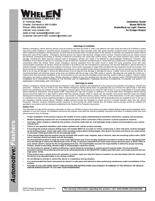
©2002 Whelen Engineering Company Inc.Form No.13721B (072105)For warranty information regarding this product, visit /warrantyA u t o m o t i v e : •Proper installation of this product requires the installer to have a good understanding of automotive electronics, systems and procedures.•Whelen Engineering requires the use of waterproof butt splices and/or connectors if that connector could be exposed to moisture.•Any holes, either created or utilized by this product, should be made both air- and watertight using a sealant recommended by your vehicle manufacturer.•Failure to use specified installation parts and/or hardware will void the product warranty.•If mounting this product requires drilling holes, the installer MUST be sure that no vehicle components or other vital parts could be damaged by the drilling process. Check both sides of the mounting surface before drilling begins. Also de-burr the holes and remove any metal shards or remnants. Install grommets into all wire passage holes.•If this manual states that this product may be mounted with suction cups, magnets, tape or Velcro®, clean the mounting surface with a 50/50 mix of isopropyl alcohol and water and dry thoroughly.•Do not install this product or route any wires in the deployment area of your air bag. Equipment mounted or located in the air bag deployment area will damage or reduce the effectiveness of the air bag, or become a projectile that could cause serious personal injury or death. Refer to your vehicle owner’s manual for the air bag deployment area. The User/Installer assumes full responsibility to determine proper mounting location, based on providing ultimate safety to all passengers inside the vehicle.•For this product to operate at optimum efficiency, a good electrical connection to chassis ground must be made. The recommendedprocedure requires the product ground wire to be connected directly to the NEGATIVE (-) battery post (this does not include products that use cigar power cords).•If this product uses a remote device for activation or control, make sure that this device is located in an area that allows both the vehicle and the device to be operated safely in any driving condition.•Do not attempt to activate or control this device in a hazardous driving situation.•It is recommended that these instructions be stored in a safe place and referred to when performing maintenance and/or reinstallation of this product.•FAILURE TO FOLLOW THESE SAFETY PRECAUTIONS AND INSTRUCTIONS COULD RESULT IN DAMAGE TO THE PRODUCT OR VEHICLE AND/OR SERIOUS INJURY TO YOU AND YOUR PASSENGERS!Warnings to InstallersWhelen’s emergency vehicle warning devices must be properly mounted and wired in order to be effective and safe. Read and follow all of Whelen’s written instructions when installing or using this device. Emergency vehicles are often operated under high speed stressful conditions which must be accounted for when installing all emergency warning devices. Controls should be placed within convenient reach of the operator so that they can operate the system without taking their eyes off the roadway. Emergency warning devices can require high electrical voltages and/or currents. Properly protect and use caution around live electrical connections.Grounding or shorting of electrical connections can cause high current arcing, which can cause personal injury and/or vehicle damage, including fire. Many electronic devices used in emergency vehicles can create or be affected by electromagnetic interference. Therefore, after installation of any electronic device it is necessary to test all electronic equipment simultaneously to insure that they operate free of interference from other components within the vehicle. Never power emergency warning equipment from the same circuit or share the same grounding circuit with radio communication equipment. All devices should be mounted in accordance with the manufacturer’s instructions and securely fastened to vehicle elements of sufficient strength to withstand the forces applied to the device. Driver and/or passenger air bags (SRS) will affect the way equipment should be mounted. This device should be mounted by permanent installation and within the zones specified by the vehicle manufacturer, if any. Any device mounted in the deployment area of an air bag will damage or reduce the effectiveness of the air bag and may damage or dislodge the device. Installer must be sure that this device, its mounting hardware and electrical supply wiring does not interfere with the air bag or the SRS wiring or sensors. Mounting the unit inside the vehicle by a method other than permanent installation is not recommended as unit may become dislodged during swerving; sudden braking or collision. Failure to follow instructions can result in personal injury. Whelen assumes no liability for any loss resulting from the use of this warning device. PROPER INSTALLATION COMBINED WITH OPERATOR TRAINING IN THE PROPER USE OF EMERGENCY WARNING DEVICES IS ESSENTIAL TO INSURE THE SAFETY OF EMERGENCY PERSONNEL AND THE PUBLIC.Warnings to UsersWhelen’s emergency vehicle warning devices are intended to alert other operators and pedestrians to the presence and operation of emergency vehicles and personnel. However, the use of this or any other Whelen emergency warning device does not guarantee that you will have the right-of-way or that other drivers and pedestrians will properly heed an emergency warning signal. Never assume you have the right-of-way. It is your responsibility to proceed safely before entering an intersection, driving against traffic, responding at a high rate of speed, or walking on or around traffic lanes. Emergency vehicle warning devices should be tested on a daily basis to ensure that they operate properly. When in actual use, the operator must ensure that both visual and audible warnings are not blocked by vehicle components (i.e.: open trunks or compartment doors), people, vehicles, or other obstructions. It is the user’s responsibility to understand and obey all laws regarding emergency warning devices. The user should be familiar with all applicable laws and regulations prior to the use of any emergency vehicle warning device. Whelen’s audible warning devices are designed to project sound in a forward direction away from the vehicle occupants. However, because sustained periodic exposure to loud sounds can cause hearing loss, all audible warning devices should be installed and operated in accordance with the standards established by the National Fire Protection Association.Safety FirstThis document provides all the necessary information to allow your Whelen product to be properly and safely installed. Before beginning the installation and/or operation of your new product, the installation technician and operator must read this manual completely. Important information is contained herein that could prevent serious injury or damage.Installation Guide Model IBF5150Brake/Back-up Light Flasherfor Dodge Intrepid51 Winthrop RoadChester, Connecticut 06412-0684Phone: (860) 526-9504Internet: Salese-mail:*******************CustomerServicee-mail:*******************®ENGINEERING COMPANY INC.IMPORTANT! The use of a Brake/Back-up Light Flasher System may be regulated by state, county or municipal authorities. It is the responsibility of the end user to comply with these regulations.The Whelen IBF5150 Brake/Back-Up Light Flasher will alternately flash the vehicle’s rear brake lights with the back-up lights at a rate of 110 flashes per minute.WARNING! The installation of a Brake/Back-Up Light Flasher System requires a modification to the vehicle’s brake light wiring harness. This modification may not only effect the warranty of your vehicle, but may also have an adverse effect on the operation of some of the safety features installed on your particular vehicle’s Brake Warning and Anti-Lock Braking Systems.Variations can exist between identical vehicles within a given model year. It is the responsibility of the end user to not only verify the warranty conditions with the vehicle manufacturer, but also verify that this device is compatible with the specific vehicle into which it is being installed. The use of a Brake/Back-Up Light flasher System may shorten bulb life.WARNING! Disconnect the battery from electrical system before attempting any part of this installation.Installation:1.Mount the IBF5150 Brake/Back-Up Light Flasher in a convenient area of the vehicle’s trunk, safe from mechanical damage. The mounting flanges have holes and slots sized to accommodate #10 mounting hardware.2.BLACK WIRE, GROUND - Connect the black wire to a good chassis ground. Wire may be extended with an 18 AWG wire.3.ORANGE WIRE, FLASHER ON/OFF CONTROL - Connect the orange wire to a customer supplied ON/OFF switch rated for at least 200ma. The switch must be connected to positive (+) 12 volts D.C. Wire may be extended with an 18 AWG wire.4.YELLOW WIRE, LEFT BRAKE LIGHT OUTPUT.5.GREEN WIRE, RIGHT BRAKE LIGHT OUTPUT.6.WHITE/BLUE WIRE, BACK-UP LIGHT INPUT.7.BLUE WIRE, BACK-UP LIGHT OUTPUT.8.RED WIRE POWER SOURCE. Connect the red wire to a high current positive (+) 12 volt D.C. power source. Fuse this circuit with a customer supplied 20 amp fuse as close to power source as possible. Wire may be extended with a 14AWG wire.WARNING! All customer supplied wires that connect to the positive (+) terminal of the battery, must be sized to supply at least 125% of the maximum operating current,and fused “at the battery” to carry that load!9.WHITE-GREEN WIRE, RIGHT BRAKE INPUT.10.WHITE-YELLOW WIRE, LEFT BRAKE INPUT.Operation:When the flasher control switch is activated to the ON position, the left and right brake lights will flash on and off together and will alternate with the back-up lights. During operation you may hear a regular clicking sound coming from the IBF5150. This means that the flasher is working properly, however it does not guarantee that the lights are flashing. It is a good practice to visually check the operation of the flasher system at regular intervals.IMPORTANT: When snapping the AMP connector together, you must be sure that the two locking latches snap into place. First make sure the connectors orientation is correct (the halfs will only fit together if they are in the correct position). Next push the connector together while pushing the locking latches forward with your thumbs until you hear an audible click. If the latch is difficult to snap, you may slide a flat blade screwdriver under the latch and push forward. DO NOT PRY UP ON THE LATCH.。
VP500-TF2Z346EN模块型3口驻留压力释放类三口阀门说明书

2 Specifications
2.1 Valve specifications
Fluid
Type of actuation
Internal pilot operating pressure range [MPa] Note 1)
Air N.C. Standard: 0.2 to 0.7
3 Installation - continued
• Products compliant with IP65 enclosures are protected against dust and water, however, these products cannot be used in water.
High pressure: 0.2 to 1.0 MPa
Operating and ambient temperatures [°C] Flow characteristics Response time Duty cycle Max. operating frequency [Hz] Manual override
ranges.
2.3 Indicator light In the DIN terminal type, the light is installed in the connector.
Surge voltage suppressor (for D/Y Z)
Light (for D/Y Z)
Figure 1.
• Contact SMC for altitude limitations.
Caution
• Temperature of ambient environment Use the valve within the range of the ambient temperature specification of each valve. In addition, pay attention when using the valve in environments where the temperature changes drastically.
- 1、下载文档前请自行甄别文档内容的完整性,平台不提供额外的编辑、内容补充、找答案等附加服务。
- 2、"仅部分预览"的文档,不可在线预览部分如存在完整性等问题,可反馈申请退款(可完整预览的文档不适用该条件!)。
- 3、如文档侵犯您的权益,请联系客服反馈,我们会尽快为您处理(人工客服工作时间:9:00-18:30)。
Description and Application Manual Dual-Channel Plug-and-play SCALE IGBT Driver 2SD316EI for EconoDUAL IGBT ModulesAbstractThe 2SD316EI is a dual-channel driver based on CONCEPT’s proprietary SCALE chipset, a proven technology for the reliable driving and safe operation of IGBTs.The driver is matched to EconoDUAL IGBT modules. Its plug-and-play capability makes it ready to operate immediately after mounting. The user need invest no effort in designing or adjusting it to a specific application.Fig. 1 2SD316EI driver and basic board screwed onto a EconoDUAL IGBT moduleDescription and Application ManualContentsSystem Overview (4)The Eight Steps to Success (5)1. Calculate the power dissipation of the IGBT modules (5)2. Choose a suitable driver / basic board pair (5)3. Design the power stack (5)4. Attach the drivers to the IGBT modules (5)5. Connect the driver to the control electronics (6)6. Select the operating mode (6)7. Check the driver function (6)8. Set-up and test the power stack (6)Pin Designation of SCALE Driver 2SD316EI (7)Pin designation of interface X1 (7)Recommended Interface Circuitry (7)Description of Interface X1 (8)General (8)VDC terminals (9)VDD terminals (9)Mod (input, mode selection) (9)ResetQ (input) (10)InA, InB (drive inputs, e.g. PWM) (10)SOx (status outputs) (11)LED-Status Indicators (channel-status indicators) (12)Basic Board: The Plug-and-Play Adapter Board (12)Protection Concept (13)Power-supply monitoring (13)Short-circuit and overcurrent protection (13)Active clamping (15)Bibliography (16)The Information Source: SCALE Driver Data Sheets (17)Description and Application Manual Quite Special: Customized SCALE Drivers (17)Evaluation Systems (17)Customer-Specific Systems (17)Consulting and Training (18)Technical Support (18)Quality (18)Disclaimer (18)Ordering Information (19)Manufacturer (19)Description and Application ManualSystem OverviewThe standard package of EconoDUAL modules covers several voltage and current ratings (e.g. 150, 225, 300, and 450A at 1200 and 1700V). Some driver parameters must therefore be matched to the relevant module. As shown in Figs. 1 and 2, this is done by placing all specific components on a separate basic board which is completely assembled and tested by CONCEPT. (The customer must order the basic board corresponding to the relevant IGBT module.)Fig. 2 Separation of universal (left) and IGBT-specific functions (right)The basic board contains all gate resistors, gate-clamping and active-clamping diodes (overvoltage protection) as well as the diodes for the collector-sense function (surge-current and short-circuit protection). Moreover, it includes components for setting the turn-off trip level and the response time. It contains only the usual through-hole components and can consequently be easily adjusted by the user to fit any special needs and applications.The 2SD316EI driver is a complex PCB equipped with SMD components such as CONCEPT’s proprietary chipset. It is mounted on top of the relevant basic board by means of spacer bolts. The standardized 2SD316EI driver matches all modules within the EconoDUAL series. It is based on the proven SCALE technology developed by CONCEPT and implemented more than a hundred thousand times. For further information on this technology, refer to /1/ and /2/.Description and Application ManualThe Eight Steps to SuccessThe following steps point out the easy way to design high-power converters by using 2SD316EI drivers with EconoDUAL modules:1. Calculate the power dissipation of the IGBT modulesFirst choose the EconoDUAL IGBT module suited for your application and determine its specific on-state and switching losses. This data is used to approximate the size of the required heat sink.2. Choose a suitable driver / basic board pairWhen applying 2SD316EI drivers for EconoDUAL modules, you should note that the basic boards are specifically adapted to a particular type of IGBT module.The type designation of the basic board consequently also includes the type designation of the corresponding module.These basic boards are valid only for the specified IGBT modules. Neglect of this warning may lead to failure.3. Design the power stackWhen designing a power stack, be sure to minimize the parasitic inductances.To speed-up your startup with 2SD316EI drivers for EconoDUAL modules, CONCEPT offers ready-to-use evaluation systems. For more information please contact CONCEPT. Some key issues relating to component selection are discussed in /4/.4. Attach the drivers to the IGBT modulesAny handling of IGBT modules or drivers is subject to the generalspecifications for protecting electrostatic-sensitive devices accordingto international standard IEC 747-1, Chapter IX or European standardEN 100015 (i.e. the workplace, tools, etc. must comply with thesestandards). If these specifications are ignored, both IGBTs andDescription and Application ManualThe driver can be easily mounted onto an IGBT module by soldering the basic board pins. The driver is then screwed onto the basic board by means of the spacer bolts.The connection between the SCALE driver and the basic board is made by two modular cables. Be sure to verify that the connectors are properly snapped-in.5. Connect the driver to the control electronicsConnect the driver plug X1 to your control electronics and supply the driver with a voltage of +15V.6. Select the operating modeThe operating mode can be set with input MOD (interface X1: pin 17). For details, see page 9.7. Check the driver functionCheck the gate voltage: For the off-state, the nominal gate voltage is –15V. For the on-state, it is +15V. Also check the input current consumption of the driver without clock signals and at the desired switching frequency.It is recommended that these tests be performed before installation, as the gate terminals may otherwise not be accessible.8. Set-up and test the power stackBefore starting up the system, you are recommended to check each IGBT module separately under power-cycling conditions. It is usually sufficient to apply the single or double-pulse technique.The short-circuit behavior can now be verified.After this step, the system is ready to start under real-world load conditions. This allows the thermal behavior of the whole arrangement to be determined. The system must now be re-qualified over the entire specified range of temperature and load conditions.CAUTION: The data contained in this product description isintended exclusively for technically trained staff.Handlingall high-voltage equipment involves risk to life. Strictcompliance with the respective safety regulations ismandatory!Description and Application ManualPin Designation of SCALE Driver 2SD316EI Pin designation of interface X11 VDC (+15V for DC/DC converter)2 GND3 VDC (+15V for DC/DC converter)4 GND5 VDD (+15V for electronic input side)6 GND7 VDD (+15V for electronic input side)8 GND9 SO2 (Status output channel 2) 10 GND 11 InB (Input B) 12 GND 13 SO1 (Status output channel 1) 14 GND 15 InA (Input A) 16 GND 17 Input Mod (mode selection) 18 GND 19 ResetQ 20 GNDRecommended Interface Circuitry+15VPWM 1PWM 2Error 1Error 2GNDReset ModusFig. 3 Recommended user interface of 2SD316EI drivers for EconoDUAL modulesDescription and Application ManualDescription of Interface X1GeneralThe interface of the 2SD316EI driver is very simple and easy to use.The driver has the following terminals:2 x PWM inputs (drive signals)2 x status outputs (failure returns)4 x power-supply terminals (but only one 15V power supply is needed)1 x reset input1 x mode selection (half-bridge mode / direct mode)The driver is equipped with a 20-pin interface connector. All even-numbered pins are used as GND connections. The odd-numbered pins are used as inputs or status outputs. It is recommended to use a 20-pin twisted flat cable. Each input and output signal is then twisted with its own GND wire. All GND pins are connected together on the SCALE driver and should also be connected on the control-board side. This arrangement produces a very low-inductance connection with high immunity against interference.Description and Application ManualFor improved noise immunity, the driver’s input signals have 15V levels. (The 5V operating mode of the SCALE chipset is not available for this driver.)All inputs have Schmitt-trigger characteristics and are ESD-protected by diodes.VDC terminalsThe driver has two VDC terminals on the interface connector. In normal operation, these terminals are connected together to the common +15V voltage supply.VDD terminalsThe driver has two VDD terminals on the interface connector. In normal operation, these terminals are connected together to the common +15V voltage supply.VDD and VDC terminals can be connected to a single +15V power supply.Mod (input, mode selection)The Mod input allows the operating mode to be selected.Half-bridge modeIf input Mod is low (connected to GND), half-bridge mode is selected, see Fig. 5. In this mode, the inputs InA and InB have the following functions: InA is the PWM signal input while InB acts as the enable input.-15V Gate G2InA Gate G1InBFig. 5 Signals in half-bridge modeDescription and Application ManualWhen input InB is low, both channels of the half-bridge are blocked. If it goes high, both channels are enabled and follow the signal on the input InA. At the transition of InA from low to high, channel 1 turns off immediately and channel 2 turns on after a dead time. The dead times are set by RC networks on the SCALE driver.Direct modeIf input Mod is high (connected to VDD), direct mode is selected. In this mode, there is no interdependence between the two channels. Input InA directly influences channel 1 (low-side IGBT) while InB influences channel 2 (high-side IGBT). High at an input (InA or InB) always results in turn-on of the corresponding IGBT. This mode should be selected only when the dead times are generated by the control circuitry so that each IGBT receives its own drive signal. In this mode, both channels can be driven either synchronously or with overlapping timing (i.e. for parallel resonance converters). Caution: Synchronous or overlapping timing of both switches of a half-bridge basically shorts the DC link.The input Mod has a built-in 4k7 pull-up resistor and Schmitt-trigger characteristics. ResetQ (input)The terminal ResetQ has a built-in 4k7 pull-up resistor and Schmitt-trigger characteristics. If not used, it can be either left open or connected via an additional pull-up resistor to VDD.If the terminal ResetQ is pulled down (by transistor Q1) to GND, then:a) The error memory of the driver (in the interface chip LDI 001) is reset, assumingthat it had been set earlierb) Both driver channels are blocked (both IGBTs are turned off)The error memories are initially set when the SCALE driver starts up. They can be reset by temporarily connecting the input ResetQ to GND (after start-up, controlled by a power-up signal). An automatic reset is then applied at the first edge of the drive signals provided that the blocking time has already elapsed (on both channels). So it is recommended to wait approx. 2 seconds after connecting the supply voltage (VDD and VDC) to the driver before applying signals to the inputs InA or InB.InA, InB (drive inputs, e.g. PWM)These are basically PWM inputs, but their function depends on the Mod input (see above). These inputs only accept 15V logic (designed for high noise immunity). They have built-in 4k7 pull-down resistors and Schmitt-trigger characteristics.Description and Application Manual SOx (status outputs)The outputs SOx have open-collector transistors (see Fig. 6). When an error condition is detected in channel “x”, the output goes to low (connected to GND). Otherwise, the output has high impedance.Both SOx outputs can be connected together to provide a common error signal. However, it is recommended to evaluate the status signals individually to allow a fast and precise failure diagnosis.The outputs SOx can be connected to the +5V...+15V power supply via a pull-up resistor (the voltage at SOx must not exceed the VDD level). The outputs SOx can handle a maximum current of 1.5 mA. To ensure a clean logic signal, it is recommended to apply a filter and a Schmitt trigger gate to SOx.VCCVLFig. 6 Block diagram of the LDI 001Description and Application ManualHow the status information is processedEach transition in a drive signal leads to:a) An error-memory reset of LDI 001b) Transfer of status information from IGD 001 to LDI 001c) If a failure is detected by IGD 001 (during the blocking time), the error memory inLDI 001 is set.External resetThe error memory may also be reset by temporarily connecting the input ResetQ to GND. Under a failure condition, the error memory is set with the next transition of the input signal.LED-Status Indicators (channel-status indicators)To facilitate verification, the driver is equipped with green status LEDs (for each of both channels). They are located on the SCALE driver close to the output connectors (refer to Fig. 1) and light up under normal operation. A turned-off LED means that the respective channel is either inactive or is not supplied with VDC voltage. Moreover, under failure conditions, the driver is blocked for approx. 1 second, thus switching the LEDs to their off-state for the same period.Note that verification, in particular of sporadic malfunctions, is impaired when the status outputs are connected together. It is therefore recommended to check both SOx signals individually and to use the information supplied by the respective status LEDs.Basic Board: The Plug-and-Play Adapter BoardThe basic board contains all gate resistors, gate-clamping and active-clamping diodes (overvoltage protection) as well as the diodes for the collector-sense function (and short-circuit protection). Moreover, it also includes components for setting the turn-off trip level and the response time.When applying 2SD316EI drivers for EconoDUAL modules, you should note that the basic boards are adapted to a particular type of IGBT module. The type designation of the basic board consequently also includes the type designation of the corresponding IGBT module.Description and Application Manual These basic boards are valid only for the specified IGBT modules. Neglect of this warning may lead to failure.The driver is adapted to EconoDUAL IGBT modules. Its plug-and-play capability means that it is ready to operate immediately after mounting. The user need not invest any effort in designing or adjusting the driver to a specific application. The basic board contains only the usual through-hole components and can therefore be easily adjusted by the user to fit any special needs and applications.The basic boards are assembled with the smallest possible gate resistor in order to minimize switching losses.Protection ConceptOnly a brief overview will now be given of the functions of the SCALE driver chipset used here. For further information about the chipset, refer to /1/.Power-supply monitoringAn under-voltage monitoring circuit blocks the driver if the supply voltage drops below about 10…11V. In this case, the IGBT is driven with a negative gate voltage to keep it in the off-state. A failure condition is transmitted.The monitoring is performed locally on each channel (integrated in the IGD 001). Short-circuit and overcurrent protectionEach channel of a SCALE driver is equipped with a V ce-monitoring circuit. The circuit is inactive during the response time applied to ensure that the IGBT is fully turned on (see Fig. 7).Description and Application ManualIn the event of failure due to V ce monitoring or power-supply under-voltage lock-out, the IGBT is kept in the off-state for a blocking time during which all drive signals are ignored. The blocking time is applied independently to each channel by IGD 001. It starts when V ce exceeds the threshold of the V ce -monitoring circuit. With the next transition of the drive signal, the “error” information is transferred for storage to the LDI 001, whose respective status output SOx goes to low. The driver then ignores any drive signal. The error information is reset only at a first transition in the drive signal after expiry of the blocking time. This automatic reset is shown in Fig. 8. The error memories can also be reset by temporarily pulling the ResetQ terminal to GND.0V -15V0A0V+15V +15V 1Gate voltageDriver t = Power-transistor turn-off in case of overcurrent t - t = Blocking time (all input signals are ignored)010(LDI 001)(IGD 001)inputFig. 8 Short-circuit and overcurrent protection. Automatic reset of the failure condition after expiry of the blocking timeDescription and Application ManualActive clampingSimple gate driving leads to the typical turn-off transition shown in Fig. 9. Turn-off with a specified minimum gate resistance is critical, particularly for trench-gate IGBT chips (such as those used in EconoDUAL modules), due to the high rate of decrease of the collector current. To minimize turn-off losses, therefore, the 2SD316EI features an active clamping function. This technique is designed to turn the IGBT on partially whenever the collector-emitter voltage exceeds a predefined threshold. The IGBT is then kept in linear operation. The basic circuitry is shown in Fig. 10.VgeIcVcettt0t1t2t3t4Vce(max) = Vdc + Vtrt5VtrVdcFig. 9 Test circuit (left) and typical switching characteristics (right)Legend to Fig. 9t0 = Initiation of the turn-off processt1 = Start of collector-emitter voltage rise t2 = Start of collector current drop t3 = Maximum collector-emitter voltage t4 = IGBT is blocking, start of tail current t5 = End of tail currentIn comparison with other driving methods, active clamping allows enhanced utilization of the IGBT modules during normal operation by increasing the switching speed and thus reducing switching losses. Furthermore, active clamping manages the over-voltage under changed operating conditions.Description and Application ManualThe active clamping function should not lead the user to forget about the inductances of the power stack.IcFig. 10 Basic circuitry for active clampingBibliography/1/ Description and Application Manual for SCALE Drivers, CONCEPT/2/ The “SCALE” IGBT Driver, a new, scalable, compact, all purpose, low cost, easy-to-use driver for IGBTs, H. Rüedi & P. Köhli, PCIM 1998 Proceedings/3/ Modular SCALE Driver Solution for EconoPACK+, H. Rüedi, PCIM 2001 Proceedings/4/ Development of Modular High-Power IGBT Stacks, H. Rüedi & D.Tollik, PCIM 2001 ProceedingsNote: These papers are available on the Internet at /go/papersDescription and Application Manual The Information Source: SCALE Driver Data Sheets CONCEPT offers the widest selection of gate drivers for power MOSFETs and IGBTs for almost any application needs. The largest website on gate-drive circuitry anywhere contains all data sheets, application notes and manuals, technical information and support sections: Quite Special: Customized SCALE DriversIf you need an IGBT driver that is not included in the delivery range, please don’t hesitate to contact CONCEPT or your CONCEPT sales partner.CONCEPT engineers have more than 20 years experience in the development and manufacture of intelligent gate drivers for power MOSFETs and IGBTs and have already implemented a large number of customized solutions.Evaluation SystemsThe evaluation systems used with EconoDUAL modules are designed particularly for development, verification, qualification and testing. They contain IGBTs, driver boards and DC-link capacitors, completely mounted and 100% tested. CONCEPT offers systems with various heat sinks or without coolers.For details see: /go/EconoDUALCustomer-Specific SystemsCONCEPT develops and produces complete power equipment and systems according to the customer’s specifications.Description and Application ManualConsulting and TrainingCONCEPT provides consulting and training services to customers on optimal procedures in power control, ideal circuit topologies as well as general do’s and don’ts in the development of power electronics.Technical SupportCONCEPT provides expert help with your questions and problems:/go/supportQualityThe obligation to high quality is one of the central features laid down in the mission statement of CT-Concept Technology Ltd. The quality management system covers all stages of product development and production up to delivery. The drivers of the SCALE series are manufactured according to the ISO9001:2000 quality standard.DisclaimerThis data sheet specifies devices but cannot promise to deliver any specific characteristics. No warranty or guarantee is given – either expressly or implicitly – regarding delivery, performance or suitability.CT-Concept Technology AG reserves the right to make modifications to its technical data and product specifications at any time without prior notice. The general terms and conditions of delivery of CT-Concept Technology AG apply.Description and Application Manual Ordering InformationThe general terms and conditions of delivery of CT-Concept Technologie AG apply. Related IGBT CONCEPT Driver Type #1200V EconoDUAL IGBTs 2SD316EI-121700V EconoDUAL IGBTs 2SD316EI-17Connection CONCEPT Modular Cable Type #2SD316EI-xx to DB01-xxx (all types) MIC01A (2 items per driver)Related IGBT CONCEPT Basic Board Type #See current list on /go/EconoDUALInformation about Other ProductsFor drivers adapted to other high-voltage or high-power IGBT modules Direct link: /go/plug-and-playFor other drivers and evaluation systemsPlease click: ManufacturerCT-Concept Technologie AGIntelligent Power ElectronicsRenferstrasse 15CH-2504 Biel-BienneSwitzerlandTel. +41 - 32 - 344 47 47Fax +41 - 32 - 344 47 40E-mail Info@Internet © Copyright 2005…2007 by CT-Concept Technologie AG - Switzerland. All rights reserved. We reserve the right to make any technical modifications without prior notice. Version of 2007-07-11。