SW5905_DataSheet
IR公司_大功率MOS管选型

I DContinuous Drain Current(A)70°Micro3Surface Mount PackagesV (BR)DSSDrain-to-Source Breakdown Voltage (V)R DS(on)On-State Resistance ()ΩI D Continuous Drain Current 25°C(A)R ΘMax.Thermal Resistance (°C/W)1FaxonDemand Number Case Outline KeyPartNumberPD Max.PowerDissipation (W)N-ChannelLogic LevelIRLML2402*912570.54200.25 1.20.95230H1IRLML2803912580.54300.251.20.93230P-ChannelLogic LevelIRLML6302*912590.54-200.6-0.62-4.8230H1IRLML5103912600.54-300.6-0.61-4.8230* Indicates low VGS(th), which can operate at VGS = 2.7VMeasured at ambient for Micro3, Micro6, Micro8, SO-8, and SOT-223 package styles. All others measured at case.1Micro3SO-8D-PakD -PakSOT-227Micro6SOT-223Micro82 Illustrations not to scaleI DContinuous Drain Current(A)70°Micro6Surface Mount PackagesV (BR)DSSDrain-to-Source Breakdown Voltage (V)R DS(on)On-State Resistance ()ΩI D Continuous Drain Current 25°C(A)R ΘMax.Thermal Resistance (°C/W)1FaxonDemand Number Case Outline KeyPartNumberPD Max.PowerDissipation (W)N-ChannelLogic LevelIRLMS1902915401.7200.10 3.2 2.675H2IRLMS1503915081.7300.103.22.675P-ChannelLogic LevelIRLMS6702*914141.7-200.20-2.3-1.975H2IRLMS5703914131.7-300.20-2.3-1.975* Indicates low VGS(th), which can operate at VGS = 2.7VMeasured at ambient for Micro3, Micro6, Micro8, SO-8, and SOT-223 package styles. All others measured at case.1Micro3SO-8D-PakD -PakSOT-227Micro6SOT-223Micro82 Illustrations not to scaleI DContinuous Drain Current(A)70°Micro8Surface Mount PackagesV (BR)DSSDrain-to-Source Breakdown Voltage (V)R DS(on)On-State Resistance ()ΩI D Continuous Drain Current 25°C(A)R ΘMax.Thermal Resistance (°C/W)1FaxonDemand Number Case Outline KeyPart NumberP D Max.PowerDissipation (W)N-Channel Logic LevelIRF7601* 912611.820 0.035 5.7 4.6 70 H3IRF7603 912621.830 0.035 5.6 4.5 70Dual N-Channel Logic LevelIRF7501* 912651.220 0.135 2.4 1.9 100 H3IRF7503 912661.2530 0.135 2.4 1.9 100P-Channel Logic LevelIRF7604* 912631.8-20 0.09 -3.6 -2.9 70 H3IRF7606 912641.8-30 0.09 -3.6 -2.9 70Dual P-Channel Logic LevelIRF7504* 912671.25-20 0.27 -1.7 -1.4 100 H3IRF7506 912681.25-30 0.27 -1.7 -1.4 100Dual N- and P-Channel Logic LevelIRF7507* 912691.2520 0.1352.4 1.9 100 H3-20 0.27 -1.7 -1.4IRF7509 912701.2530 0.135 2.4 1.9 100-30 0.27 -1.7 -1.4* Indicates low VGS(th), which can operate at VGS = 2.7VMeasured at ambient for Micro3, Micro6, Micro8, SO-8, and SOT-223 package styles. All others measured at case.1Micro3SO-8D-Pak D -PakSOT-227Micro6SOT-223Micro8 2 Illustrations not to scaleI DContinuous Drain Current(A)70°SO-8Surface Mount PackagesV (BR)DSSDrain-to-Source Breakdown Voltage (V)R DS(on)On-State Resistance ()ΩI D Continuous Drain Current 25°C(A)R ΘMax.Thermal Resistance (°C/W)1FaxonDemand Number Case Outline KeyPart Number P D Max.PowerDissipation (W)N-ChannelIRF7413913302.5300.011139.250H4IRF7413A 916132.5300.0135128.450IRF9410915622.5300.0375.850Dual N-ChannelIRF7311914352.0200.029 6.6 5.362.5H4IRF7313914802.0300.029 6.5 5.262.5IRF7333917002.0300.10 3.5 2.862.5917002.0300.050 4.9 3.962.5IRF9956915592.0300.103.52.862.5Dual P-ChannelIRF7314914352.0-200.058-5.3-4.362.5H4IRF7316915052.0-300.058-4.9-3.962.5IRF9953915602.0-300.25-2.3-1.862.5* Indicates low VGS(th), which can operate at VGS = 2.7VMeasured at ambient for Micro3, Micro6, Micro8, SO-8, and SOT-223 package styles. All others measured at case.1Micro3SO-8D-PakD -PakSOT-227Micro6SOT-223Micro82 Illustrations not to scaleI DContinuous Drain Current(A)70°SO-8Surface Mount PackagesV (BR)DSSDrain-to-Source Breakdown Voltage (V)R DS(on)On-State Resistance ()ΩI D Continuous Drain Current 25°C(A)RΘMax.ThermalResistance(°C/W)1FaxonDemand Number Case Outline KeyPart NumberP D Max.PowerDissipation (W)Dual N- and P-ChannelIRF7317 915682.020 0.029 6.6 5.3 62.5 H42.0-20 0.058 -5.3 -4.3 62.5IRF9952 915622.030 0.103.5 2.8 62.5915622.0-30 0.25 -2.3 -1.8 62.5IRF7319 916062.030 0.029 6.5 5.2 62.52.0-30 0.058 -4.9 -3.9 62.5* Indicates low VGS(th), which can operate at VGS = 2.7VMeasured at ambient for Micro3, Micro6, Micro8, SO-8, and SOT-223 package styles. All others measured at case.1Micro3SO-8D-Pak D -PakSOT-227Micro6SOT-223Micro8 2 Illustrations not to scaleI DContinuous Drain Current(A)70°SO-8Surface Mount PackagesV (BR)DSSDrain-to-Source Breakdown Voltage (V)R DS(on)On-State Resistance ()ΩI D Continuous Drain Current 25°C(A)R ΘMax.Thermal Resistance (°C/W)1FaxonDemand Number Case Outline KeyPart Number P D Max.PowerDissipation (W)N-ChannelLogic LevelIRF7401912442.5200.0228.77.050H4IRF7201911002.5300.0307.0 5.650IRF7403912452.5300.0228.55.450Dual N-ChannelLogic LevelIRF7101908712.0200.10 3.5 2.362.5H4IRF7301912382.0200.050 5.2 4.162.5IRF7303912392.0300.050 4.9 3.962.5IRF7103910952.0500.1303.02.362.5P-ChannelLogic LevelIRF7204911032.5-200.060-5.3-4.250H4IRF7404912462.5-200.040-6.7-5.450IRF7205911042.5-300.070-4.6-3.750IRF7406912472.5-300.045-5.8-3.750IRF7416913562.5-300.02-10-7.150* Indicates low VGS(th), which can operate at VGS = 2.7VMeasured at ambient for Micro3, Micro6, Micro8, SO-8, and SOT-223 package styles. All others measured at case.1Micro3SO-8D-PakD -PakSOT-227Micro6SOT-223Micro82 Illustrations not to scaleI DContinuous Drain Current(A)70°SO-8Surface Mount PackagesV (BR)DSSDrain-to-Source Breakdown Voltage (V)R DS(on)On-State Resistance ()ΩI D Continuous Drain Current 25°C(A)R ΘMax.Thermal Resistance (°C/W)1FaxonDemand Number Case Outline KeyPart Number P D Max.PowerDissipation (W)Dual P-ChannelLogic LevelIRF7104910962.0-200.250-2.3-1.862.5H4IRF7304912402.0-200.090-4.3-3.462.5IRF7306912412.0-300.10-3.6-2.962.5Dual N- and P-Channe Logic LevelIRF7307912421.4200.050 4.3 3.490H4-200.090-3.6-2.9IRF7105910972.0250.1093.5 2.862.52-250.25-2.3-1.862IRF7309912432.0300.050 4.9 3.962.5-300.10-3.6-2.9* Indicates low VGS(th), which can operate at VGS = 2.7VMeasured at ambient for Micro3, Micro6, Micro8, SO-8, and SOT-223 package styles. All others measured at case.1Micro3SO-8D-PakD -PakSOT-227Micro6SOT-223Micro82 Illustrations not to scaleI DContinuous Drain Current(A)70°SOT-223Surface Mount PackagesV (BR)DSSDrain-to-Source Breakdown Voltage (V)R DS(on)On-State Resistance ()ΩI D Continuous Drain Current 25°C(A)R ΘMax.Thermal Resistance (°C/W)1FaxonDemand Number Case Outline KeyPart Number P D Max.PowerDissipation (W)N-ChannelIRFL4105913812.1550.045 3.7 3.060H6IRFL110908612.01000.54 1.50.9660IRFL4310913682.11000.20 1.6 1.360IRFL21090868 2.02001.50.960.660IRFL214908622.02502.00.790.560P-ChannelIRFL9110908642.0-1001.2-1.1-0.6960H6N-ChannelLogic LevelIRLL3303913792.1300.031 4.6 3.760H6IRLL014N 914992.1550.14 2.0 1.660IRLL2705913802.1550.043.83.060* Indicates low VGS(th), which can operate at VGS = 2.7VMeasured at ambient for Micro3, Micro6, Micro8, SO-8, and SOT-223 package styles. All others measured at case.1Micro3SO-8D-PakD -PakSOT-227Micro6SOT-223Micro82 Illustrations not to scaleI DContinuous Drain Current(A)100°D-PakSurface Mount PackagesV (BR)DSSDrain-to-Source Breakdown Voltage (V)R DS(on)On-State Resistance ()ΩI D Continuous Drain Current 25°C(A)R ΘMax.Thermal Resistance (°C/W)1FaxonDemand Number Case Outline KeyPart Number P D Max.PowerDissipation (W)N-ChannelIRFR33039164257300.0313321 2.2H7IRFR024N9133638550.0751610 3.3IRFR41059130248550.0452516 2.7IRFR12059131869550.0273723 1.8IRFR11090524251000.54 4.3 2.75IRFR120N 91365391000.219.1 5.8 3.2IRFR391091364521000.11159.5 2.4IRFR2109052625200 1.5 2.6 1.75IRFR22090525422000.8 4.833IRFR21490703252502 2.2 1.45IRFR2249060042250 1.1 3.8 2.43IRFR3109059725400 3.6 1.7 1.15IRFR3209059842400 1.8 3.123IRFR42090599425003 2.4 1.53IRFRC2090637426004.421.33* Indicates low VGS(th), which can operate at VGS = 2.7VMeasured at ambient for Micro3, Micro6, Micro8, SO-8, and SOT-223 package styles. All others measured at case.1Micro3SO-8D-PakD -PakSOT-227Micro6SOT-223Micro82 Illustrations not to scaleI DContinuous Drain Current(A)100°D-PakSurface Mount PackagesV (BR)DSSDrain-to-Source Breakdown Voltage (V)R DS(on)On-State Resistance ()ΩI D Continuous Drain Current 25°C(A)R ΘMax.Thermal Resistance (°C/W)1FaxonDemand Number Case Outline KeyPart Number P D Max.PowerDissipation (W)P-ChannelIRFR55059161057-550.11-18-11 2.2H7IRFR53059140289-550.065-28-18 1.4IRFR90149065425-600.5-5.1-3.25IRFR90249065542-600.28-8.8-5.63IRFR91109051925-100 1.2-3.1-25IRFR91209052042-1000.6-5.6-3.63IRFR9120N 9150739-1000.48-6.5-4.1 3.2IRFR92109052125-2003-1.9-1.25IRFR92209052242-200 1.5-3.6-2.33IRFR92149165850-250 3.0-2.7-1.7 2.5IRFR93109166350-4007.0-1.8-1.12.5* Indicates low VGS(th), which can operate at VGS = 2.7VMeasured at ambient for Micro3, Micro6, Micro8, SO-8, and SOT-223 package styles. All others measured at case.1Micro3SO-8D-PakD -PakSOT-227Micro6SOT-223Micro82 Illustrations not to scaleI DContinuous Drain Current(A)100°D-PakSurface Mount PackagesV (BR)DSSDrain-to-Source Breakdown Voltage (V)R DS(on)On-State Resistance ()ΩI D Continuous Drain Current 25°C(A)R ΘMax.Thermal Resistance (°C/W)1FaxonDemand Number Case Outline KeyPart Number P D Max.PowerDissipation (W)N-ChannelLogic LevelIRLR27039133538300.0452214 3.3H7IRLR33039131657300.0313321 2.2IRLR31039133369300.0194629 1.8IRLR024N 9136338550.0651711 3.3IRLR27059131746550.042415 2.7IRLR29059133469550.0273623 1.8IRLR120N 91541391000.18511 6.9 3.2IRLR341091607521000.10159.52.4* Indicates low VGS(th), which can operate at VGS = 2.7VMeasured at ambient for Micro3, Micro6, Micro8, SO-8, and SOT-223 package styles. All others measured at case.1Micro3SO-8D-PakD -PakSOT-227Micro6SOT-223Micro82 Illustrations not to scaleI DContinuous Drain Current(A)100°D 2PakSurface Mount PackagesV (BR)DSSDrain-to-Source Breakdown Voltage (V)R DS(on)On-State Resistance ()ΩI D Continuous Drain Current 25°C(A)R ΘMax.Thermal Resistance (°C/W)1FaxonDemand Number Case Outline KeyPart NumberP D Max.PowerDissipation (W)N-ChannelIRFZ24NS 913554555 0.07 17 12 3.3 H10IRFZ34NS 913116855 0.04 29 20 2.2IRFZ44NS 9131511055 0.022 49 35 1.4IRFZ46NS 9130512055 0.020 53 37 1.3IRFZ48NS 9140814055 0.016 64 45 1.1IRF1010NS 913723.855 0.011 84 60 40IRF3205S 9130420055 0.008 110 80 0.75IRFZ44ES 9171411060 0.023 48 34 1.4IRF1010ES 9172017060 0.012 83 59 0.90IRF2807S 9151815075 0.013 71 50 1.0IRF520NS 9134047100 0.2 9.5 6.7 3.2IRF530NS 9135263100 0.11 15 11 2.4IRF540NS 91342110100 0.052 27 19 1.6IRF1310NS 91514120100 0.036 36 25 1.3IRF3710S 91310150100 0.028 46 33 1.0IRF3315S 9161794150 0.082 21 15 1.6IRF3415S 91509150150 0.042 37 26 1.0IRFBC20S 9.101450600 4.4 2.2 1.4 2.5IRFBC30S 9101574600 2.2 3.6 2.3 1.7IRFBC40S 91016130600 1.2 6.2 3.9 1.0* Indicates low VGS(th), which can operate at VGS = 2.7VMeasured at ambient for Micro3, Micro6, Micro8, SO-8, and SOT-223 package styles. All others measured at case.1Micro3SO-8D-Pak D -PakSOT-227Micro6SOT-223Micro8 2 Illustrations not to scaleI DContinuous Drain Current(A)100°D 2PakSurface Mount PackagesV (BR)DSSDrain-to-Source Breakdown Voltage (V)R DS(on)On-State Resistance ()ΩI D Continuous Drain Current 25°C(A)R ΘMax.Thermal Resistance (°C/W)1FaxonDemandNumberCase Outline KeyPart NumberP D Max.PowerDissipation (W)IRFBF20S 9166554900 8.0 1.7 1.1 2.3 H10P-ChannelIRF5305S 91386110-55 0.06 -31 -22 1.4 H10IRF4905S 914783.8-55 0.02 -74 -52 40IRF9520NS 9152247-100 0.48 -6.7 -4.8 3.2IRF9530NS 9152375-100 0.20 -14 -9.9 2.0IRF9540NS 9148394-100 0.117 -19 -13 1.6IRF5210S 91405150-100 0.06 -35 -25 1.0* Indicates low VGS(th), which can operate at VGS = 2.7VMeasured at ambient for Micro3, Micro6, Micro8, SO-8, and SOT-223 package styles. All others measured at case.1Micro3SO-8D-Pak D -PakSOT-227Micro6SOT-223Micro8 2 Illustrations not to scaleI DContinuous Drain Current(A)100°D 2PakSurface Mount PackagesV (BR)DSSDrain-to-Source Breakdown Voltage (V)R DS(on)On-State Resistance ()ΩI D Continuous Drain Current 25°C(A)R ΘMax.Thermal Resistance (°C/W)1FaxonDemand Number Case Outline KeyPart NumberP D Max.PowerDissipation (W)N-Channel Logic LevelIRL3302S 916925720 0.020 39 25 2.2 H10IRL3202S916756920 0.016 48 30 1.8IRL3102S 916918920 0.013 61 39 1.4IRL3402S 9169311020 0.01 85 54 1.1IRL3502S 9167614020 0.007 110 67 0.89IRL2703S 913604530 0.04 24 17 3.3IRL3303S 913236830 0.026 38 27 2.2IRL3103S 9133811030 0.014 64 45 1.4IRL2203NS 9136717030 0.007 116 82 0.90IRL3803S 9131920030 0.006 140 98 0.75IRLZ24NS 913584555 0.06 18 13 3.3IRLZ34NS 913086855 0.035 30 21 2.2IRLZ44NS 9134711055 0.022 47 33 1.4IRL3705NS 9150217055 0.01 89 63 0.90IRL2505S 9132620055 0.008 104 74 0.75IRLZ44S 9090615060 0.028 50 36 1.0IRL530NS 9134963100 0.1 15 11 2.4IRL2910S 91376150100 0.026 48 34 1.0* Indicates low VGS(th), which can operate at VGS = 2.7VMeasured at ambient for Micro3, Micro6, Micro8, SO-8, and SOT-223 package styles. All others measured at case.1Micro3SO-8D-Pak D -PakSOT-227Micro6SOT-223Micro8 2 Illustrations not to scaleI DContinuous Drain Current(A)100°SOT-227Surface Mount PackagesV (BR)DSSDrain-to-Source Breakdown Voltage (V)R DS(on)On-State Resistance ()ΩI D Continuous DrainCurrent 25°C(A)RΘMax.Thermal Resistance (°C/W)1FaxonDemand Number Case Outline KeyPart Number P D Max.PowerDissipation (W)N-ChannelFully Isolated Low ChargeFA38SA50LC 916155005000.1338240.25H21FA57SA50LC916506255000.0857360.20* Indicates low VGS(th), which can operate at VGS = 2.7VMeasured at ambient for Micro3, Micro6, Micro8, SO-8, and SOT-223 package styles. All others measured at case.1Micro3SO-8D-PakD -PakSOT-227Micro6SOT-223Micro82 Illustrations not to scaleI DContinuous Drain Current(A)100°I-PakThrough-Hole PackagesV (BR)DSSDrain-to-Source Breakdown Voltage (V)R DS(on)On-State Resistance ()ΩI D Continuous Drain Current 25°C(A)R ΘMax.Thermal Resistance (°C/W)1FaxonDemand Number Case Outline KeyPart Number P D Max.PowerDissipation (W)N-ChannelIRFU33039164257300.0313321 2.2H8IRFU024N 9133638550.0751610 3.3IRFU41059130248550.0452519 2.7IRFU12059131869550.0273723 1.8IRFU11090524251000.54 4.3 2.7 5.0IRFU120N 91365391000.219.1 5.8 3.2IRFU391091364521000.11159.5 2.4IRFU2109052625200 1.5 2.6 1.7 5.0IRFU22090525422000.80 4.8 3.0 3.0IRFU2149070325250 2.0 2.2 1.4 5.0IRFU2249060042250 1.1 3.8 2.4 3.0IRFU3109059725400 3.6 1.7 1.1 5.0IRFU3209059842400 1.8 3.1 2.0 3.0IRFU4209059942500 3.0 2.4 1.5 3.0IRFUC2090637426004.42.01.33.0I-PakTO-220 FullPakTO-262TO-247HEXDIPTO-220AB Illustrations not to scale** Not ratedI DContinuous Drain Current(A)100°I-PakThrough-Hole PackagesV (BR)DSSDrain-to-Source Breakdown Voltage (V)R DS(on)On-State Resistance ()ΩI D Continuous Drain Current 25°C(A)R ΘMax.Thermal Resistance (°C/W)1FaxonDemand Number Case Outline KeyPart Number P D Max.PowerDissipation (W)P-ChannelIRFU55059161057-550.11-18-11 2.2H8IRFU53059140289-550.065-28-18 1.4IRFU90149065425-600.50-5.1-3.2 5.0IRFU90249065542-600.28-8.8-5.6 3.0IRFU91109051925-100 1.2-3.1-2.0 5.0IRFU91209052042-1000.60-5.6-3.6 3.0IRFU9120N 9150739-1000.48-6.5-4.1 3.2IRFU92109052125-200 3.0-1.9-1.2 5.0IRFU92209052242-200 1.5-3.6-2.3 3.0IRFU92149165850-2503.0-2.7-1.7 2.5IRFU93109166350-4007.0-1.8-1.12.5N-ChannelLogic LevelIRLU27039133538300.0452214 3.3H8IRLU33039131657300.0313321 2.2IRLU31039133369300.0194629 1.8IRLU024N 9136338550.0651711 3.3IRLU27059131746550.04241715IRLU29059133469550.0273623 1.8IRLU120N 91541391000.18511 6.9 3.2IRLU341091607521000.10159.52.4I-PakTO-220 FullPakTO-262TO-247HEXDIPTO-220AB Illustrations not to scale** Not ratedI DContinuous Drain Current(A)100°HEXDIPThrough-Hole PackagesV (BR)DSSDrain-to-Source Breakdown Voltage (V)R DS(on)On-State Resistance ()ΩI D Continuous Drain Current 25°C(A)R ΘMax.Thermal Resistance (°C/W)1FaxonDemand Number Case Outline KeyPart Number P D Max.PowerDissipation (W)N-ChannelIRFD014907001.3600.2 1.7 1.2120H9IRFD024906991.3600.1 2.5 1.8120IRFD110903281.31000.54 1.00.71120IRFD120903851.31000.27 1.30.94120IRFD210903861.3200 1.50.60.38120IRFD220904171.32000.80.80.50120IRFD214912711.3250 2.00.570.32120IRFD224912721.3250 1.10.760.43120IRFD310912251.3400 3.60.420.23120IRFD320912261.3400 1.80.600.33120IRFD420912271.3500 3.00.460.26120IRFDC20912281.36004.40.320.21120I-PakTO-220 FullPakTO-262TO-247HEXDIPTO-220AB Illustrations not to scale** Not ratedI D Continuous Drain Current (A)100°TO-220Qg TotalGate Charge(nC)Through-Hole PackagesV (BR)DSSDrain-to-Source Breakdown Voltage (V)R DS(on)On-State Resistance ()ΩI D Continuous Drain Current 25°C (A)R ΘMax.Thermal Resistance(°C/W)1Faxon Demand Number Case OutlineKeyPart Number P D Max.Power Dissipation (W)N-ChannelLow ChargeIRF737LC91314743000.75 6.1** 1.7 3.9H11IRF740LC 910681254000.5510** 1.039IRF840LC 910691255000.858.0** 1.039IRFBC40LC910701256001.26.2**1.039I-PakTO-220 FullPakTO-262TO-247HEXDIPTO-220AB Illustrations not to scale** Not ratedI DContinuous Drain Current(A)100°TO-220ABThrough-Hole PackagesV (BR)DSSDrain-to-Source Breakdown Voltage (V)R DS(on)On-State Resistance ()ΩI D Continuous Drain Current 25°C(A)R ΘMax.Thermal Resistance (°C/W)1FaxonDemand Number Case Outline KeyPart Number P D Max.PowerDissipation (W)N-ChannelIRFZ24N 9135445550.071712 3.3H12IRFZ34N9127656550.042618 2.7IRFZ44N 9130383550.0244129 1.8IRFZ46N 9127788550.024633 1.7IRFZ48N 9140694550.0165337 1.6IRF1010N 91278130550.0127251 1.2IRF320591279150550.0089869 1.0IRFZ34E 9167268600.0422820 2.2IRFZ44E 91671110600.0234834 1.4IRF1010E 91670170600.01281570.90IRF280791517150750.0137150 1.0IRF520N 91339471000.209.5 6.79.5IRF530N 91351601000.111511 2.4IRF540N 91341941000.0522719 1.6IRF1310N 916111201000.0363625 1.3IRF3710913091501000.0284633 1.0IRF331591623941500.0822115 1.6IRF3415914771501500.0423726 1.0IRFBC209062350600 4.4 2.2 1.4 2.5IRFBC309048274600 2.2 3.6 2.3 1.7IRFBC4090506125600 1.2 6.2 3.9 1.0IRFBE2090610548006.51.81.22.3I-PakTO-220 FullPakTO-262TO-247HEXDIPTO-220AB Illustrations not to scale** Not ratedI DContinuous Drain Current(A)100°TO-220ABThrough-Hole PackagesV (BR)DSSDrain-to-Source Breakdown Voltage (V)R DS(on)On-State Resistance ()ΩI D Continuous Drain Current 25°C(A)R ΘMax.Thermal Resistance (°C/W)1FaxonDemand Number Case Outline KeyPart Number P D Max.PowerDissipation (W)IRFBE3090613125800 3.0 4.1 2.6 2.0H12IRFBF3090616125900 3.7 3.6 2.3 1.0IRFBG209060454100011 1.40.86 2.3IRFBG309062012510005.03.12.01.0P-ChannelIRF9Z24N 9148445-550.175-12-8.53.3H12IRF9Z34N 9148556-550.10-17-12 2.7IRF530591385110-550.06-31-22 1.4IRF490591280150-550.02-64-45 1.0IRF9530N 9148275-1000.20-13-9.2 2.0IRF9540N 9143794-1000.117-19-13 1.6IRF521091434150-1000.06-35-25 1.0IRF62159147983-1500.29-11-7.81.8I-PakTO-220 FullPakTO-262TO-247HEXDIPTO-220AB Illustrations not to scale** Not ratedI DContinuous Drain Current(A)100°TO-220ABThrough-Hole PackagesV (BR)DSSDrain-to-Source Breakdown Voltage (V)R DS(on)On-State Resistance ()ΩI D Continuous Drain Current 25°C(A)R ΘMax.Thermal Resistance (°C/W)1FaxonDemand Number Case Outline KeyPart NumberP D Max.PowerDissipation (W)N-Channel Logic LevelIRL3302 916965720 0.020 39 25 2.2 H12IRL3202 916956920 0.016 48 30 1.8IRL3102 916948920 0.013 61 39 1.4IRL3402 9169711020 0.01 85 54 1.1IRL3502 9169814020 0.007 110 67 0.89IRL2703 913594530 0.04 24 17 3.3IRL3303 913225630 0.026 34 24 2.7IRL3103 913378330 0.014 56 40 1.8IRL2203N 9136613030 0.007 100 71 1.230 0.007 61 43 3.2IRL3803 9130115030 0.006 120 83 1.0IRLZ24N 913574555 0.06 18 13 3.3IRLZ34N 913075655 0.035 27 19 2.7IRLZ44N 913468355 0.022 41 29 1.8IRL3705N 9137013055 0.01 77 54 1.2IRL2505 9132520055 0.008 104 74 0.75IRL520N 9149447100 0.18 10 7.1 3.2IRL530N 9134863100 0.10 15 11 2.4IRL540N 9149594100 0.044 30 21 1.6IRL2910 91375150100 0.026 48 34 1.0I-PakTO-220 FullPakTO-262TO-247HEXDIPTO-220AB Illustrations not to scale** Not ratedI D Continuous Drain Current (A)100°TO-220 FullPak (Fully Isolated)Qg TotalGate Charge(nC)Through-Hole PackagesV (BR)DSSDrain-to-Source Breakdown Voltage (V)R DS(on)On-State Resistance ()ΩI D Continuous DrainCurrent 25°C(A)R ΘMax.Thermal Resistance (°C/W)1Fax on Demand Number Case OutlineKeyPart Number P D Max.Power Dissipation (W)N-ChannelLow ChargeIRFI740GLC91209404000.55 6.0** 3.139H13IRFI840GLC 91208405000.85 4.8** 3.139IRFIBC40GLC91211406001.24.0**3.139I-PakTO-220 FullPakTO-262TO-247HEXDIPTO-220AB Illustrations not to scale** Not ratedI DContinuous Drain Current(A)100°TO-220 FullPak (Fully Isolated)Through-Hole PackagesV (BR)DSSDrain-to-Source Breakdown Voltage (V)R DS(on)On-State Resistance ()ΩI D Continuous Drain Current 25°C(A)R ΘMax.Thermal Resistance (°C/W)1FaxonDemand Number Case Outline KeyPart Number P D Max.PowerDissipation (W)N-ChannelIRFIZ24N 9150126550.07139.2 5.8H14IRFIZ34N9148931550.041913 4.8IRFIZ44N 9140338550.02428200.024IRFIZ46N 9130640550.023122 3.8IRFIZ48N 9140742550.0163625 3.6IRFI1010N 9137347550.0124431 3.2IRFI32059137448550.0085640 3.1IRFIZ24E 9167329600.071149.6 5.2IRFIZ34E 9167437600.0422115 4.1IRFI510G 90829271000.54 4.5 3.2 5.5IRFI520N 91362271000.207.2 5.1 5.5IRFI530N 91353331000.11117.8 4.5IRFI540N 91361421000.0521813 3.6IRFI1310N 91611451000.0362216 3.3IRFI371091387481000.0252820 3.1IRFI620G 90832302000.8 4.1 2.6 4.1IRFI630G 90652322000.4 5.9 3.7 3.6IRFI640G 90649402000.189.8 6.2 3.1IRFI614G 9083123250 2.0 2.1 1.3 5.5IRFI624G 9083330250 1.1 3.4 2.2 4.1IRFI634G 90738322500.45 5.6 3.5 3.6IRFI644G 90739402500.287.953.1I-PakTO-220 FullPakTO-262TO-247HEXDIPTO-220AB Illustrations not to scale** Not ratedI DContinuous Drain Current(A)100°TO-220 FullPak (Fully Isolated)Through-Hole PackagesV (BR)DSSDrain-to-Source Breakdown Voltage (V)R DS(on)On-State Resistance ()ΩI D Continuous Drain Current 25°C(A)R ΘMax.Thermal Resistance (°C/W)1FaxonDemand Number Case Outline KeyPart Number P D Max.PowerDissipation (W)IRFI720G 9083430400 1.8 2.6 1.7 4.1H14IRFI730G 9065032400 1.0 3.7 2.3 3.6IRFI740G 90651404000.55 5.4 3.4 3.1IRFI734G 9100135450 1.2 3.4 2.1 3.6IRFI744G 91002404500.63 4.9 3.1 3.1IRFI820G 9064130500 3.0 2.1 1.3 4.1IRFI830G 9064632500 1.5 3.12 3.6IRFI840G 90642405000.85 4.6 2.9 3.1IRFIBC20G 90850306004.41.71.1 4.1IRFIBC30G 90851356002.2 2.5 1.63.6IRFIBC40G 9085240600 1.2 3.5 2.2 3.1IRFIBE20G 9085330800 6.5 1.4.86 4.1IRFIBE30G 9085435800 3.0 2.1 1.4 3.6IRFIBF20G 90855309008.0 1.2.79 4.1IRFIBF30G90856359003.71.91.23.6P-ChannelIRFI9Z24N 9152929-550.175-9.5-6.7 5.2H14IRFI9Z34N 9153037-550.10-14-10 4.1IRFI49059152663-550.02-41-29 2.4IRFI9540G 9083742-1000.117-13-9.2 3.6IRFI9540N 9148742-1000.117-13-9.2 3.6IRFI52109140448-1000.06-20-14 3.1IRFI9634G 9148835-2501.0-4.1-2.63.6I-PakTO-220 FullPakTO-262TO-247HEXDIPTO-220AB Illustrations not to scale** Not ratedI DContinuous Drain Current(A)100°TO-220 FullPak (Fully Isolated)Through-Hole PackagesV (BR)DSSDrain-to-Source Breakdown Voltage (V)R DS(on)On-State Resistance ()ΩI D Continuous Drain Current 25°C(A)R ΘMax.Thermal Resistance (°C/W)1FaxonDemand Number Case Outline KeyPart Number P D Max.PowerDissipation (W)N-ChannelLogic LevelIRLI2203N 9137847300.0076143 3.2H14IRLI38039132048300.0066747 3.1IRLIZ24N 9134426550.06149.9 5.8IRLIZ34N 9132931550.0352014 4.8IRLIZ44N 9149838550.0222820 4.0IRLI3705N 9136947550.014733 3.2IRLI25059132763550.00858412.4IRLI520N 91496271000.187.7 5.4 5.5IRLI530N 91350331000.10117.8 4.5IRLI540N 91497421000.04420143.6IRLI291091384481000.02627193.1P-ChannelLogic LevelIRFI9520G 9083537-1000.6-5.2-3.6 4.1H14IRFI9530G 9083638-1000.03-7.7-5.4 3.6IRFI9620G 9087430-200 1.5-3.0-1.9 4.1IRFI9630G 9083840-2000.8-4.3-2.7 3.6IRFI9640G9083940-2000.5-6.1-3.93.1I-PakTO-220 FullPakTO-262TO-247HEXDIPTO-220AB Illustrations not to scale** Not ratedI D Continuous Drain Current (A)100°TO-247Qg TotalGate Charge(nC)Through-Hole PackagesV (BR)DSSDrain-to-Source Breakdown Voltage (V)R DS(on)On-State Resistance ()ΩI D Continuous Drain Current 25°C (A)R ΘMax.Thermal Resistance (°C/W)1Fax on Demand Number Case OutlineKeyPart Number P D Max.Power Dissipation (W)1N-ChannelLow ChargeIRFP350LC912291904000.3018**0.6570H16IRFP360LC 912302804000.2023**0.4598IRFP450LC 912311905000.4016**0.6570IRFP460LC 912322805000.2720**0.4598IRFPC50LC 912331906000.6013**0.6570IRFPC60LC912342806000.4016**0.4598I-PakTO-220 FullPakTO-262TO-247HEXDIPTO-220AB Illustrations not to scale** Not rated。
户外P6表贴三合一显示屏参数

LED 显示屏品牌企业————《三思》
第 1 页 共 2 页
P6户外表贴产品参数(温度条件:Ta=25℃)
产品名称
LR-P6-4S-32x32-3535(户外表贴)
光学
特性
LED 封装方式 SMD 3535 白灯五面刷墨
红光芯片及波长 晶元 620-625 红光芯片尺寸 10mil 反极性 绿光芯片及波长 台湾晶元520-525 绿光芯片尺寸 9*13 mil 正极性 蓝光芯片及波长 台湾晶元 467-472 蓝光芯片尺寸
9*13 mil 正极性 水平可视角度 ≥130(+10/-10)度 垂直可视角度
≥120(+10/-10)度 亮度 ≥8000CD/㎡(实测)
像素点间距 6mm 像素密度 27777Dots/㎡
像素构成 1RGB 单元板分辨率 32*32=1024Dots
驱动方式以及IC
四扫(恒流) GW6018/SUM2016
最佳视距 5m~36m 物理特性
单元板尺寸(长*宽)
192mm*192mm
单元板重量 400±10g 单元板变形高度 ≤0.5mm 结构特点 灯驱合一
刷新频率
1920HZ 电学特性
单组驱动白平衡电流 红色 14mA
绿色11mA 蓝色8mA 单元板最大电流 4.5A 单元板最大功率 23W 平均无故障时间 ≥1万小时 使用寿命 ≥10万小时 像素失控率 ﹤1/100000
使用环境
使用环境 户外 工作温度范围 -20至50℃ 工作湿度范围 10%至90% RH 存储温度范围 0至40℃ 存储湿度范围
30%至60% RH
第 2 页共2 页。
B82793S0513N201;B82793C475N265;中文规格书,Datasheet资料

Data and signal line chokesCommon-mode chokes, ring core0.005 … 47 mH, 100 … 1200 mA, 60 °CSeries/Type:B82793C0/S0Date:July 2010¤ EPCOS AG 2010. Reproduction, publication and dissemination of this publication, enclosures hereto and the information contained therein without EPCOS’ prior express consent is prohibited.Rated voltage 42 V AC/80 V DCRated inductance 0.005 mH to 47 mH Rated current 100 mA to 1200 mA Construction■Current-compensated double choke ■Ferrite core■LCP case (UL 94 V-0), silicone potting ■Bifilar winding (B82793C0)■Sector winding (B82793S0)Features■High rated currents, reduced components height ■Qualified to AEC-Q200 (L d 4.7 mH)■Suitable for reflow soldering ■RoHS-compatibleFunction■B82793C0:Suppression of asymmetrical interference coupled in on lines,whereas data signals up to some MHz can pass unaffectedly.■B82793S0:Suppression of asymmetrical and symmetrical interference (by L stray )coupled in on lines. The high-frequency portions of the symmetrical data signal are decreased so far that EMC problems can be significantly reduced.Applications■Automotive applications, e.g. CAN bus ■Industrial applications■Types with L R ! 4.7 mH only for telecom applicationsTerminals■Base material CuSn6■Layer composition Ni, Sn ■Hot-dippedMarking■Marking on component: Manufacturer, process location (coded),winding method (coded), ordering code (short form), date of manufacture (YWWD)■Minimum data on reel: Manufacturer, ordering code,L value and tolerance, quantity, date of packing Delivery mode and packing unit■16-mm blister tape, wound on 330-mm reel ■Packing unit: 1500 pcs./reel Common-mode chokes, ring coreDimensional drawing and pin configurationLayout recommendationTaping and packing Blister tapeReelDimensions in mmDimensions in mmCommon-mode chokes, ring coreCommon-mode chokes, ring coreTechnical data and measuring conditionsRated voltage V R42 V AC (50/60 Hz) / 80 V DCRated temperature T R60 °CRated current I R Referred to 50 Hz and rated temperatureRated inductance L R Measured with Agilent 4284A, 0.1 mA, 20 °CMeasuring frequency:L R d 1 mH = 100 kHzL R! 1 mH = 10 kHzInductance is specified per winding.Inductance tolerance r30% (L R d0.47mH), –30/+50% (L R t1mH) at 20 °C Inductance decrease 'L/L 10% at DC magnetic bias with I R, 20 °CStray inductance L stray,typ Measured with Agilent 4284A, 5 mA, 20 °C, typical valuesMeasuring frequency:L R d 11 P H = 1 MHzL R! 11 P H = 100 kHzDC resistance R typ Measured at 20q C, typical values, specified per winding Solderability SnPb:(215 r3) °C, (3 r0.3) sSn96.5Ag3.0Cu0.5:(245 r5) °C, (3 r0.3) sWetting of soldering area t 95%(to IEC 60068-2-58)Resistance to soldering heat(260 r5) °C, (10 r1) s (to IEC 60068-2-58)Climatic category 40/125/56 (to IEC 60068-1)Storage conditions (packaged)–25 °C … +40 °C, d 75% RHWeight Approx. 0.25 gCharacteristics and ordering codes Sample kit available. Ordering code: B82793X001.For more information refer to chapter “Sample kits”.L R mH L stray,typ nH I R mA R typ m :V test V DC, 2 s Ordering code 0.005 40120060250B82793C0502N2010.011 50 80080250B82793C0113N2010.025 60 800110250B82793C0253N2010.0251400 800110250B82793S0253N2010.051 70 800140250B82793C0513N2010.0512300 800140250B82793S0513N2010.10 100 500180250B82793C0104N2010.47 100 700170750B82793C0474N2151.0 70 700140750B82793C0105N2652.2 120 500400750B82793C0225N2654.7 250 400550750B82793C0475N265For telecommunications203001001800750B82793C0206N2654712001003700750B82793C0476N265Common-mode chokes, ring coreInsertion loss D (typical values at |Z| = 50 :, 20 °C)asymmetrical, all branches in parallel (common mode)symmetrical (differential mode)L R = 0.005 mHL R = 0.025 mH (low L stray)L R = 0.011 mHL R = 0.025 mH (high L stray)Common-mode chokes, ring coreInsertion loss D (typical values at |Z| = 50 :, 20 °C)asymmetrical, all branches in parallel (common mode)symmetrical (differential mode)L R = 0.051 mH (low L stray) L R = 0.10 mH L R = 0.051 mH (high L stray) L R = 0.47 mHCommon-mode chokes, ring coreInsertion loss D (typical values at |Z| = 50 :, 20 °C)asymmetrical, all branches in parallel (common mode)symmetrical (differential mode)L R =1.0 mH L R = 4.7 mH L R = 2.2 mH L R = 20 mHCommon-mode chokes, ring coreInsertion loss D (typical values at |Z| = 50 :, 20 °C)asymmetrical, all branches in parallel (common mode)symmetrical (differential mode)L R = 47 mH Current derating I op/I R versus ambient temperatureCommon-mode chokes, ring coreRecommended reflow soldering curvePb containing solder material (based on CECC 00802 edition 2)Pb-free solder material (based on JEDEC J-STD 020C)Time from 25 °C to T 4: max 300 s Maximal numbers of reflow cycles: 3T 1°C T 2°C T 3°C T 4°C t 1s t 2s t 3s150200217250< 110< 90< 40 @ T 4 –5 °CCommon-mode chokes, ring core分销商库存信息:EPCOSB82793S0513N201B82793C475N265。
SW259器件资料 datasheet
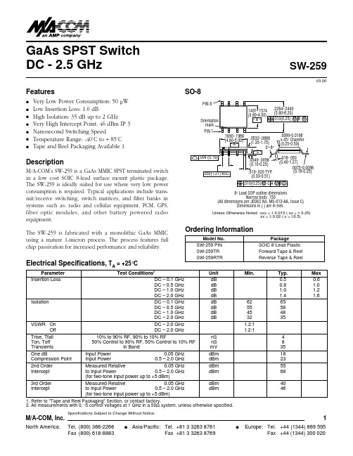
GaAs SPST Switch DC - 2.5 GHzSW-259V3.00M/A-COM, Inc.1Specifications Subject to Change Without Notice.q q q q q q qElectrical Specifications, TA = +25°CFeaturesVery Low Power Consumption: 50 µW Low Insertion Loss: 1.0 dBHigh Isolation: 35 dB up to 2 GHzVery High Intercept Point: 46 dBm IP 3 Nanosecond Switching SpeedTemperature Range: -40˚C to + 85˚C Tape and Reel Packaging Available 1DescriptionM/A-COM’s SW-259 is a GaAs MMIC SPST terminated switch in a low cost SOIC 8-lead surface mount plastic package.The SW-259 is ideally suited for use where very low power consumption is required. Typical applications include trans-mit/receive switching, switch matrices, and filter banks in systems such as: radio and cellular equipment, PCM, GPS,fiber optic modules, and other battery powered radio equipment.The SW-259 is fabricated with a monolithic GaAs MMIC using a mature 1-micron process. The process features full chip passivation for increased performance and reliability.1. Refer to "Tape and Reel Packaging" Section, or contact factory.2. All measurements with 0, -5 control voltages at 1 GHz in a 50Ωsystem, unless otherwise specified.SO-8Model No.PackageSW-259 PIN SOIC 8-Lead Plastic SW-259TR Forward Tape & Reel SW-259RTRReverse Tape & ReelOrdering InformationParameter Test Conditions 2Unit Min. Typ. Max Insertion Loss DC – 0.1 GHz dB 0.5 0.6DC – 0.5 GHz dB 0.8 1.0 DC – 1.0 GHz dB 1.0 1.2 DC – 2.0 GHz dB 1.4 1.6Isolation DC – 0.1 GHz dB 62 65DC – 0.5 GHz dB 55 58 DC – 1.0 GHz dB 45 48 DC – 2.0 GHz dB 32 35VSWR On DC – 2.0 GHz 1.2:1Off DC – 2.0 GHz 1.2:1Trise, Tfall 10% to 90% RF, 90% to 10% RF nS 4Ton, Toff 50% Control to 90% RF, 50% Control to 10% RF nS 8 Transients In Band mV 35One dB Input Power 0.05 GHz dBm 18 Compression Point Input Power 0.5 – 2.0 GHz dBm 232nd Order Measured Relative 0.05 GHz dBm 55 Intercept to Input Power 0.5 – 2.0 GHz dBm 68(for two-tone input power up to +5 dBm)3rd Order Measured Relative 0.05 GHz dBm 40 Intercept to Input Power 0.5 – 2.0 GHz dBm 46(for two-tone input power up to +5 dBm)0(0.19-0.25)8- Lead SOP outline dimensionsNarrow body .150(All dimensions per JEDEC No. MS-012-AA, Issue C)Dimensions in ( ) are in mm...010(0.25) M C A M B SUnless Otherwise Noted: .xxx = ± 0.010 (.xx = ± 0.25).xx = ± 0.02 (.x = ±0.5)V3.00M/A-COM, Inc.2Specifications Subject to Change Without Notice.Parameter Absolute Maximum 1,2Max. Input Power 0.05 GHz +27 dBm 0.5 – 2 GHz +34 dBm Control Voltage+5V, -8.5V Storage Temperature-65°C to 150°CAbsolute Maximum Ratings 11.Operation of this device above any one of these parameters may cause permanent damage2.When the RF Input power is applied to a terminated port, the absolute maximum is +32 dBm.2.01.51.00.50FREQUENCY (GHz)L O S S (d B )INSERTION LOSS vs FREQUENCYPin No.Description1 GND2 A3 B4 GND5 RF26 GND7 GND 8 RF1Pin ConfigurationControl InputsCondition of SwitchA B RF STATE 1 0 On 0 1 OffTruth Table"0" – 0 – -0.2V @ 20 µA max."1" – -5V @ 20µA Typ to -8V @ 600 µA max.Typical Performance90807060504030201000.5 1.01.52.02.5FREQUENCY (GHz)I S O L A T I O N (d B )ISOLATION vs FREQUENCY2.01.81.61.41.21.00 0.51.01.52.02.5FREQUENCY (GHz)L O S S (d B )VSWR vs FREQUENCYFunctional SchematicRF1GND GNDGNDGND RF2ABM/A-COM, Inc.3Specifications Subject to Change Without Notice.V3.000-5-10-15-20-25-30-35-4000.20.40.60.81FREQUENCY (GHz)S 22 (d B )S22 (On) vs FREQUENCY0-10-20-30-40-50-60-70-8000.20.40.60.81FREQUENCY (GHz)I S O L A T I O N (d B )ISOLATION vs FREQUENCY0-2-4-6-8-10-12-14-16-1800.20.40.60.81FREQUENCY (GHz)S 22 (d B )S22 (Off) vs FREQUENCY0-5-10-15-20-25-30-35-4000.20.40.60.81FREQUENCY (GHz)S 11 (d B )S11 (On) vs FREQUENCYSwept Data Characterized in 75 Ohms。
nichicon FW series DATA SHEET

3300
332 10 × 20 1170 12.5 × 20 1420 12.5 × 25 1700 16 × 25 1950 16 × 35.5 2220 18 × 35.5 2360 20 × 40 2700 25 × 50 2900
4700
472 12.5 × 20 1350 12.5 × 25 1800 16 × 25 2100 16 × 31.5 2360 18 × 35.5 2490 20 × 40 2900 22 × 50 3400
Series name Type
Please refer to page 21, 22, 23 about the formed or taped product spec. Please refer to page 3 for the minimum order quantity.
Dimension table in next page.
Printed with black color letter on Gold sleeve.
D+ MAX. B P ± 0.5
Radial Lead Type
Sleeve (P.E.T.)
Bd
Pressure relief vent
(B 6.3up)
L+ MAX.
15MIN
4MIN
(mm)
BD
5
6.3
tan δ
Rated voltage (V) tan δ (MAX.)
6.3 0.28
10 0.24
16 0.20
25 0.16
35 0.14
50 0.12
For capacitance of more than 1000µF, add 0.02 for every increase of 1000µF.
2004中文版ASME规范 第Ⅱ卷 A篇 铁基材料 2006增补

公制单位”用的‘IEEE/ASTM 10-1997’标准的规则。”
右栏第 2 段第 2 行中“……已在美国的 49 个州…… ”修改为:
“……已在美国的 50 个州……”。
按标准标号顺序、在 SA-240/ SA-240M 行下,新增加:
SA-263 铬- 不锈钢复合钢板
A06
SA-264 铬-镍 不锈钢复合钢板
A961 管道用钢法兰,锻造管配件及阀门零件通用要求 重新编号为 2.3 并删除‘SP25’一行。
重新编号为 2.4 并删除“ASME 锅炉及压力容器规范第 IX 卷,焊接 评定”一行。 在新 2.4 节下新增加 2.5 节如下: 2.5 ASME 锅炉及压力容器规范:
第 IX 卷,焊接评定 原 2.4 节重新编号为 2.6,内容不变。
60
SA-105
/SA-105M
5.1.5
句中‘特殊级别’后,增加上角标②,并在 5.1.5 条的译文下,增加注②
如下: ② 关于特殊磅级的定义,见 ASME B16.34。
60
SA-105
5.2
本节修改为:
/SA-105M
5.2 当第 5.1 条要求热处理时,应按 A961 标准做退火、正火、或正
在第 II 卷 A 篇和 B 篇中的非强制性附录-A 中。”。
xlvi~liv 许用的
对部分规范版本修改,另见本增补第 44~45 页。
ASTM 版本
2
Байду номын сангаас
ASME BPVC 2006 增补
第 II 卷 A 篇
铁基材料
04 中文 版页码
章节
修改部位
06 增 补 修 改 内 容
lv-lvi 材料的多重 每一段落的 对全文 7 个小标题,取消原有编号,但标题名称未改变。 性标志准则 小标题 各标题以下的内容,也没有变更。
MRFE6VP8600HSR5;MRFE6VP8600HR5;MRFE6VP8600HR6;MRFE6VP8600HSR6;中文规格书,Datasheet资料
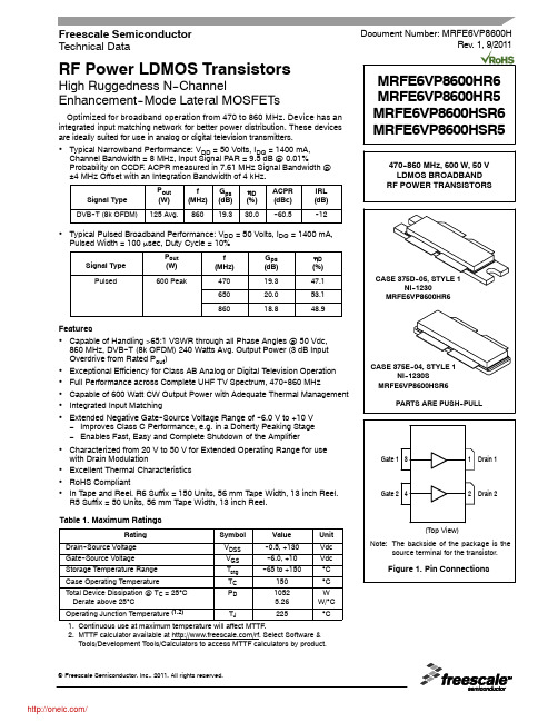
RF POWER TRANSISTORS
CASE 375D--05, STYLE 1 NI--1230
MRFE6VP8600HR6
Features
• Capable of Handling >65:1 VSWR through all Phase Angles @ 50 Vdc, 860 MHz, DVB--T (8k OFDM) 240 Watts Avg. Output Power (3 dB Input Overdrive from Rated Pout)
RF Device Data
Freescale Semiconductor
1
/
Table 2. Thermal Characteristics
Characteristic
Thermal Resistance, Junction to Case Case Temperature 74°C, 125 W CW, 50 V, 1400 mA, 860 MHz
• Typical Narrowband Performance: VDD = 50 Volts, IDQ = 1400 mA, Channel Bandwidth = 8 MHz, Input Signal PAR = 9.5 dB @ 0.01% Probability on CCDF. ACPR measured in 7.61 MHz Signal Bandwidth @ ±4 MHz Offset with an Integration Bandwidth of 4 kHz.
• Excellent Thermal Characteristics • RoHS Compliant • In Tape and Reel. R6 Suffix = 150 Units, 56 mm Tape Width, 13 inch Reel.
GS-2406T PLUS GS-3405T PLUS Series 热转式 热感式 SUR

GS-2406T PLUS / GS-3405T PLUS / Series热转式/热感式SURPASS PLUS条码印表机使用手册Ver.1.1.3Agency Compliance and ApprovalsEN 55032, Class AEN 55024This is a class A product. In a domestic environment this product may cause radiointerference in which case the user may be required to take adequate measures.FCC part 15B, Class AThis equipment has been tested and found to comply with the limits for a Class Adigital device, pursuant to Part 15 of the FCC Rules. These limits are designed toprovide reasonable protection against harmful interference when the equipment isoperated in a commercial environment. This equipment generates, uses, and canradiate radio frequency energy and, if not installed and used in accordance with themanufacturer’s instruction manual, may cause harmful interference with radiocommunications. Operation of this equipment in a residential area is likely to causeharmful interference, in which case you will be required to correct the interference atyour own expense.FCC 符合声明此设施符合第15 部份的规则。
内置时钟免校准计量芯片数据手册说明书
BL0940 datasheetBL0940免校准计量芯片数据手册版本更新说明目录版本更新说明 (2)1产品简述 (5)1.1功能简介 (5)1.2主要特点 (5)1.3系统框图 (6)1.4封装与管脚描述 (7)1.5寄存器列表 (8)1.6特殊寄存器说明 (9)1.6.1用户模式选择寄存器 (9)1.6.2温度模式控制寄存器 (10)1.7性能指标 (11)1.7.1电参数性能 (11)1.7.2极限范围 (12)2功能描述 (13)2.1电流电压瞬态波形计量 (13)2.2有功功率 (14)2.3有功功率偏置校准 (14)2.4有功功率的防潜动 (15)2.5电能计量 (16)2.6电流电压有效值 (17)2.7电流电压有效值偏置校准 (18)2.8过流检测 (18)2.9相角计算 (20)2.10过零检测 (21)2.11温度计量 (22)3通讯接口 (24)3.1SPI (24)3.1.1工作模式 (24)3.1.2帧结构 (25)3.1.3写入操作时序 (25)3.1.4读出操作时序 (26)3.1.5SPI接口的容错机制 (26)3.2UART (27)3.2.1概述 (27)3.2.2描述 (27)3.2.3每个字节格式 (27)3.2.4写入时序 (27)3.2.5读取时序 (28)3.2.6数据包发送模式 (29)3.2.7UART接口的保护机制 (30)4封装 (30)1产品简述1.1功能简介BL0940是一颗内置时钟免校准电能计量芯片,适用于单相多功能电能表、智能插座、智能家电、电动自行车充电桩等应用,具有较高的性价比。
BL0940集成了2路高精度Sigma-Delta ADC,参考电压,电源管理等模拟电路模块,以及处理有功功率、电流电压有效值等电参数的数字信号处理电路。
BL0940能够测量电流、电压有效值、有功功率、有功电能量等参数,可输出快速电流有效值(用于过流保护),以及温度检测,波形输出等功能,通过UART/SPI接口输出数据,能够充分满足智能插座、智能家电、单相多功能电能表、电动自行车充电桩及用电信息大数据采集等领域的需要。
WIRL-PRO9 915MHz 低功耗无线模块说明书

Dimensions: [mm]26070562910112607056291011Cautions and Warnings:The following conditions apply to all goods within the product series of wireless connectivity of Würth Elektronik eiSos GmbH & Co. KG:General:•This electronic component is designed and developed with the intention for use in general electronic equipment.•Würth Elektronik must be asked for written approval (following the PPAP procedure) before incorporating the components into any equipment in fields such as military, aerospace, aviation, nuclear control, submarine, transportation (automotive control, train control, ship control), transportation signal, disaster prevention, medical, public information network, etc. where higher safety and reliability are especially required and/or if there is the possibility of direct damage or human injury.•Electronic components that will be used in safety-critical or high-reliability applications, should be pre-evaluated by the customer.•The component is designed and manufactured to be used within the datasheet specified values. If the usage and operation conditions specified in the datasheet are not met, the wire insulation may be damaged or dissolved.•Do not drop or impact the components, the component may be damaged.•Würth Elektronik products are qualified according to international standards, which are listed in each product reliability report. Würth Elektronik does not guarantee any customer qualified product characteristics beyond Würth Elektroniks’ specifications, for its validity and sustainability over time.•The customer is responsible for the functionality of their own products. All technical specifications for standard products also apply to customer specific products.Product specific:Soldering:•The solder profile must comply with the technical product specifications. All other profiles will void the warranty.•All other soldering methods are at the customer’s own risk.Cleaning and Washing:•Washing agents used during the production to clean the customer application might damage or change the characteristics of the component. Washing agents may have a negative effect on the long-term functionality of the product.•Using a brush during the cleaning process could break the module. Therefore, we do not recommend using a brush during the PCB cleaning process.Potting and Coating:•If the product is potted in the costumer application, the potting material might shrink or expand during and after hardening. Shrinking could lead to an incomplete seal, allowing contaminants into the component. Expansion could damage the components. We recommenda manual inspection after potting to avoid these effects.•Conformal coating may affect the product performance.Storage Conditions:• A storage of Würth Electronik products for longer than 12 months is not recommended. Within other effects, the terminals may suffer degradation, resulting in bad solderability. Therefore, all products shall be used within the period of 12 months based on the day of shipment.•Do not expose the components to direct sunlight.•The storage conditions in the original packaging are defined according to DIN EN 61760-2.•If there is a moisture sensitive component, the storage condition in the original packaging is defined according to IPC/JEDEC-J-STD-033. It is also recommended to return the component to the original moisture proof bag and reseal the moisture proof bag again.•ESD prevention methods need to be followed for manual handling and processing by machinery.Handling:•Violation of the technical product specifications such as exceeding the nominal rated current, will void the warranty.•Violation of the technical product specifications such as but not limited to exceeding the absolute maximum ratings will void the conformance to regulatory requirements.•The Edge castellation is designed and made for prototyping, i.e. hand soldering purposes only.•Non-antenna modules must be equipped with a proper antenna having specific characteristics.•The applicable country regulations and specific environmental regulations must be observed.•Do not disassemble the product. Evidence of tampering will void the warranty.These cautions and warnings comply with the state of the scientific and technical knowledge and are believed to be accurate and reliable. However, no responsibility is assumed for inaccuracies or incompleteness.All topics are described in a more detailed manner in the manual for each product.Würth Elektronik eiSos GmbH & Co. KGEMC & Inductive SolutionsMax-Eyth-Str. 174638 WaldenburgGermanyCHECKED REVISION DATE (YYYY-MM-DD)GENERAL TOLERANCE PROJECTIONMETHODGE001.0242019-07-18DIN ISO 2768-1mDESCRIPTIONWIRL-PRO9 Radio module 915MHzlow power ORDER CODE2607056291011BUSINESS UNIT STATUS PAGEImportant NotesThe following conditions apply to all goods within the product range of Würth Elektronik eiSos GmbH & Co. KG:1. General Customer ResponsibilitySome goods within the product range of Würth Elektronik eiSos GmbH & Co. KG contain statements regarding general suitability for certain application areas. These statements about suitability are based on our knowledge and experience of typical requirements concerning the areas, serve as general guidance and cannot be estimated as binding statements about the suitability for a customer application. The responsibility for the applicability and use in a particular customer design is always solely within the authority of the customer. Due to this fact it is up to the customer to evaluate, where appropriate to investigate and decide whether the device with the specific product characteristics described in the product specification is valid and suitable for the respective customer application or not.2. Customer Responsibility related to Specific, in particular Safety-Relevant ApplicationsIt has to be clearly pointed out that the possibility of a malfunction of electronic components or failure before the end of the usual lifetime cannot be completely eliminated in the current state of the art, even if the products are operated within the range of the specifications.In certain customer applications requiring a very high level of safety and especially in customer applications in which the malfunction or failure of an electronic component could endanger human life or health it must be ensured by most advanced technological aid of suitable design of the customer application that no injury or damage is caused to third parties in the event of malfunction or failure of an electronic component. Therefore, customer is cautioned to verify that data sheets are current before placing orders. The current data sheets can be downloaded at .3. Best Care and AttentionAny product-specific notes, cautions and warnings must be strictly observed. Any disregard will result in the loss of warranty.4. Customer Support for Product SpecificationsSome products within the product range may contain substances which are subject to restrictions in certain jurisdictions in order to serve specific technical requirements. Necessary information is available on request. In this case the field sales engineer or the internal sales person in charge should be contacted who will be happy to support in this matter.5. Product R&DDue to constant product improvement product specifications may change from time to time. As a standard reporting procedure of the Product Change Notification (PCN) according to the JEDEC-Standard inform about minor and major changes. In case of further queries regarding the PCN, the field sales engineer or the internal sales person in charge should be contacted. The basic responsibility of the customer as per Section 1 and 2 remains unaffected.6. Product Life CycleDue to technical progress and economical evaluation we also reserve the right to discontinue production and delivery of products. As a standard reporting procedure of the Product Termination Notification (PTN) according to the JEDEC-Standard we will inform at an early stage about inevitable product discontinuance. According to this we cannot guarantee that all products within our product range will always be available. Therefore it needs to be verified with the field sales engineer or the internal sales person in charge about the current product availability expectancy before or when the product for application design-in disposal is considered. The approach named above does not apply in the case of individual agreements deviating from the foregoing for customer-specific products.7. Property RightsAll the rights for contractual products produced by Würth Elektronik eiSos GmbH & Co. KG on the basis of ideas, development contracts as well as models or templates that are subject to copyright, patent or commercial protection supplied to the customer will remain with Würth Elektronik eiSos GmbH & Co. KG. Würth Elektronik eiSos GmbH & Co. KG does not warrant or represent that any license, either expressed or implied, is granted under any patent right, copyright, mask work right, or other intellectual property right relating to any combination, application, or process in which Würth Elektronik eiSos GmbH & Co. KG components or services are used.8. General Terms and ConditionsUnless otherwise agreed in individual contracts, all orders are subject to the current version of the “General Terms and Conditions of Würth Elektronik eiSos Group”, last version available at .Würth Elektronik eiSos GmbH & Co. KGEMC & Inductive SolutionsMax-Eyth-Str. 174638 WaldenburgGermanyCHECKED REVISION DATE (YYYY-MM-DD)GENERAL TOLERANCE PROJECTIONMETHODGE001.0242019-07-18DIN ISO 2768-1mDESCRIPTIONWIRL-PRO9 Radio module 915MHzlow power ORDER CODE2607056291011BUSINESS UNIT STATUS PAGE。
Fujitsu CELSIUS W580 微型台式机工作站产品说明书

Data Sheet Fujitsu CELSIUS W580Fujitsu recommends Windows 10 Pro for business.Data SheetFujitsu CELSIUS W580Mini CAD PowerhouseIf you thought you would need to sacrifice performance, expandability, price or energy efficiency in a microtower design – think again. As an industry first, the FUJITSU CELSIUS W580 desktop workstation goes far and beyond with its innovative 21-liter, space-saving microtower design.No compromise in terms of performance, expandability and priceDesigned with CAD customers in mind: performance, reliability and great flexibility - at an affordable priceChoose between the energy-efficient Intel® Core™ processors or the powerful Intel® Xeon® E-2200 processor familySupport of Windows 10 Pro64 GB DDR4 2,666 MHz memory (incl. ECC) Maximum capacity of 16 TBBoost your storage performance with super-fast PCIe SSDsIndustry’s smallest VR-ready desktop workstation Innovative space-saving design - made in EuropeAn industry first: 21-liter desktop microtower workstationNVIDIA® Quadro® RTX 4000 VR-ready graphics (with CELSIUS W580power) Optimized thermal management and cooling solutionsEnjoy a silent workplace environment, thanks to low noise emission down to 18 dB(A) (depending on configuration)Multi-monitor experienceIdeal for showrooms, control rooms, surveillance or financial services companies Up to 8 monitors with the NVIDIA® Mosaic™ technology2-in-1: Workstation and Point-of-Sales deviceYour workstation can be deployed as a traditional workstation as well as a point-of-sales device in any retail environmentConnect your cash drawer and your scanner to two serial portsSupport of 24/7 operation with reliable high-endurance and business critical drivesComponentsProcessor Intel® Xeon® processor E-2288G (8 Cores / 16 Threads, 3.70 GHz, up to 5.0 GHz, 16 MB)Intel® Xeon® processor E-2286G (6 Cores / 12 Threads, 4.00 GHz, up to 4.9 GHz, 12 MB)Intel® Xeon® processor E-2278G (8 Cores / 16 Threads, 3.40 GHz, up to 5.0 GHz, 16 MB)Intel® Xeon® processor E-2276G (6 Cores / 12 Threads, 3.80 GHz, up to 4.9 GHz, 12 MB)Intel® Xeon® processor E-2274G (4 Cores / 8 Threads, 4.00 GHz, up to 4.9 GHz, 8 MB)Intel® Xeon® processor E-2246G (6 Cores / 8 Threads, 3.60 GHz, up to 4.8 GHz, 12 MB)Intel® Xeon® processor E-2244G (4 Cores / 8 Threads, 3.80 GHz, up to 4.8 GHz, 8 MB)Intel® Xeon® processor E-2236 (6 Cores / 12 Threads, 3.40 GHz, up to 4.8 GHz, 12 MB)Intel® Xeon® processor E-2234 (4 Cores / 8 Threads, 3.60 GHz, up to 4.8 GHz, 8 MB)Intel® Xeon® processor E-2226G (6 Cores / 6 Threads, 3.40 GHz, up to 4.6 GHz, 12 MB)Intel® Xeon® processor E-2224G (4 Cores / 4 Threads, 3.50 GHz, up to 4.7 GHz, 8 MB)Intel® Xeon® processor E-2224 (4 Cores / 4 Threads, 3.40 GHz, up to 4.6 GHz, 8 MB)Intel® Xeon® processor E-2186G (6 Cores / 12 Threads, 3.80 GHz, up to 4.7 GHz, 12 MB, Intel® UHD Graphics P630) *Intel® Xeon® processor E-2174G (4 Cores / 8 Threads, 3.80 GHz, up to 4.7 GHz, 8 MB, Intel® UHD Graphics P630) *Intel® Xeon® processor E-2136 (6 Cores / 12 Threads, 3.30 GHz, up to 4.5 GHz, 12 MB) *Intel® Xeon® processor E-2134 (4 Cores / 8 Threads, 3.50 GHz, up to 4.5 GHz, 8 MB) *Intel® Xeon® processor E-2126G (6 Cores / 6 Threads, 3.30 GHz, up to 4.5 GHz, 12 MB, Intel® UHD Graphics P630) *Intel® Xeon® processor E-2124 (4 Cores / 8 Threads, 3.30 GHz, up to 4.5 GHz, 8 MB) *Intel® Core™ i9-9900 processor (8 Cores / 16 Threads, 3.10 GHz, up to 5.0 GHz, 16 GB, Intel® UHD Graphics 630)Intel® Core™ i9-9900K processor (8 Cores / 16 Threads, 3.60 GHz, up to 5.0 GHz, 16 GB, Intel® UHD Graphics 630)Intel® Core™ i7-9700 processor (8 Cores / 8 Threads, 3.00 GHz, up to 4.7 GHz, 12 MB, Intel® HD Graphics 630) *Intel® Core™ i7-9700K processor (8 Cores / 8 Threads, 3.60 GHz, up to 4.9 GHz, 12 MB, Intel® UHD Graphics 630) *Intel® Core™ i5-9600 processor (6 Cores / 6 Threads, 3.10 GHz, up to 4.6 GHz, 9 MB, Intel® UHD Graphics 630) *Intel® Core™ i5-9500 processor (6 Cores / 6 Threads, 3.00 GHz, up to 4.4 GHz, 9 MB, Intel® UHD Graphics 630) *Intel® Core™ i5-8600 processor (6 Cores / 6 Threads, 3.10 GHz, up to 4.3 GHz, 9 MB, Intel® UHD Graphics 630) *Intel® Core™ i3-9100 processor (4 Cores / 4 Threads, 3.60 GHz, up to 4.2 GHz, 6 MB, Intel® HD Graphics 630) *Intel® vPro® Platform with all Intel® Xeon® processorsNo Intel® vPro® technology with Intel® Core™ i5 and Core™ i7 processors*with Intel® Turbo Boost Technology 2.0 (clock speed and performance will vary depending on workload and othervariables)Operating system preinstalledOperating system pre-installed Windows 10 Pro for WorkstationsWindows 10 Pro. Fujitsu recommends Windows 10 Pro forbusiness.Windows 10 Home Windows 10 Pro for WorkstationsWindows 10 Pro. Fujitsu recommends Windows 10 Pro for business.Windows 10 HomeOperating system compatible Linux LinuxOperating system notes Certified for Red Hat© Enterprise LinuxCertified for SUSE Enterprise DesktopCertified for SUSE Enterprise ServerFor some configurations third party drivers are currentlynot available or configuration restrictions may apply.Windows 10 Support: After the end of the product lifeFUJITSU will continue to test and support all upcomingWindow 10 releases for a period of maximum 5 years –depending on the available extension of hardware servicesthrough FUJITSU Warranty top ups. For details please see“FUJITSU Service Statement for Windows 10 Semi-Annual-Channel Support” at .Certified for Red Hat© Enterprise LinuxCertified for SUSE Enterprise Desktop (pending) Certified for SUSE Enterprise Server (pending)For some configurations third party drivers are currently not available or configuration restrictions may apply. Windows 10 Support: After the end of the product life FUJITSU will continue to test and support all upcoming Window 10 releases for a period of maximum 5 years – depending on the available extension of hardware services through FUJITSU Warranty top ups. For details please see “FUJITSU Service Statement for Windows 10 Semi-Annual-Channel Support” at .Memory modules 4 GB (1 module(s) 4 GB) DDR4, unbuffered, non-ECC, 2,666 MT/s, UDIMM8 GB (1 module(s) 8 GB) DDR4, unbuffered, ECC, 2,666 MT/s, UDIMM8 GB (1 module(s) 8 GB) DDR4, unbuffered, non-ECC, 2,666 MT/s, UDIMM16 GB (1 module(s) 16 GB) DDR4, unbuffered, ECC, 2,666 MT/s, UDIMM16 GB (1 module(s) 16 GB) DDR4, unbuffered, non-ECC, 2,666 MT/s, UDIMMGraphics High-end 3D: NVIDIA® Quadro® RTX 4000, 8 GB, PCIe x16, 3 x DisplayPort, 1 x Virtual LinkMidrange 3D: NVIDIA® Quadro® P2200, 5 GB, PCIe x16, 4 x DisplayPortMidrange 3D: AMD Radeon™ Pro WX 5100, 8 GB, 320 stream processors, PCIe x16, 4 x DisplayPortEntry 3D: NVIDIA® Quadro® P1000, 4 GB, PCIe x16, 4 x miniDPEntry 3D: AMD Radeon™ Pro WX 3100, 4 GB, 320 stream processors, PCIe x16, 1 x DisplayPort, 2 x miniDPEntry 3D: AMD Radeon™ Pro WX 2100, 2 GB, 320 stream processors, PCIe x16, 1 x DisplayPort, 2 x miniDPEntry 3D: NVIDIA® Quadro® P620, 2 GB, PCIe x16, 4 x miniDPEntry 3D: NVIDIA® Quadro® P400 , 2 GB, PCIe x16, 3 x miniDPRemote Graphics: CELSIUS RemoteAccess Dual Card, PCIe x1, 2 x miniDP, PCoIPRemote Graphics: CELSIUS RemoteAccess Quad Card, PCIe x1, 4 x miniDP, PCoIPOthers: VGA Extension CardOthers: DP to DVI-D (single link) Adapter CableOthers: MiniDP to DP Adapter CableNotes NVIDIA® Quadro® P4000 requires CELSIUS W580power or CELSIUS W580power+.Hard disk drives (internal)SSD SATA III, 960 GB High Endurance, 1DWDP, 2.5-inchSSD SATA III, 480 GB High Endurance, 1DWDP, 2.5-inchSSD SATA III, 240 GB High Endurance, 1DWDP, 2.5-inchSSD PCIe, 2048 GB M.2 NVMe Highend moduleSSD PCIe, 1024 GB M.2 NVMe Highend moduleSSD PCIe, 512 GB M.2 NVMe Highend moduleSSD PCIe, 256 GB M.2 NVMe Highend moduleSSD PCIe, 1x 2048 GB M.2 NVMe Highend cardSSD PCIe, 1x1024 GB M.2 NVMe Highend cardSSD PCIe, 1x 512 GB M.2 NVMe Highend cardSSD PCIe, 1x 256 GB M.2 NVMe Highend cardRAID1 Bundle 2x512GB M.2 NVMe HighendRAID1 Bundle 2x256GB M.2 NVMe HighendSSD PCIe, 1024 GB M.2 NVMe moduleSSD PCIe, 512 GB M.2 NVMe moduleSSD PCIe, 256 GB M.2 NVMe moduleSSD PCIe, 1024 GB M.2 NVMe module, SEDSSD PCIe, 512 GB M.2 NVMe module, SEDSSD PCIe, 256 GB M.2 NVMe module, SEDSSD PCIe, 1x 1024 GB M.2 NVMe cardSSD PCIe, 1x 512 GB M.2 NVMe cardSSD PCIe, 1x 256 GB M.2 NVMe cardSSD SATA III, 1024 GB, 2.5-inchSSD SATA III, 512 GB, 2.5-inchSSD SATA III, 256 GB, 2.5-inchSSD SATA III, 128 GB, 2.5-inchHDD SATA III, 7,200 rpm, 4,000 GB, 3.5-inch, business criticalHDD SATA III, 7,200 rpm, 2,000 GB, 3.5-inch, business criticalHDD SATA III, 7,200 rpm, 1,000 GB, 3.5-inch, business criticalHDD SATA III, 7,200 rpm, 2,000 GB, 2.5-inch, business criticalHDD SATA III, 7,200 rpm, 1,000 GB, 2.5-inch, business criticalHDD SATA III, 7,200 rpm, 2,000 GB, 3.5-inchHDD SATA III, 7,200 rpm, 1,000 GB, 3.5-inchHard disk notes One Gigabyte equals one billion bytes, when referring to hard disk drive capacity.24/7 ready (business critical HDDs required)Up to 20 GB of HDD space is reserved for system recoverySSHD (Solid State Hard Disk, Hybrid drive)SED (Self-Encrypting Drive)SSD (Solid State Disk)Drives (optional)BD Triple Writer SATA ultra slim (tray)DVD-ROMDVD Super MultiDVD Super Multi ultra slim (tray)MultiCard Reader 24in1 USB 2.0 3.5”Base unitBase unit CELSIUS W580CELSIUS W580powerMainboardMainboard type D3617Chipset Intel® C246Processor socket LGA 1151Processor quantity maximum1Supported capacity RAM (max.)64 GBMemory slots 4 DIMM (DDR4) ECC/non-ECCMemory frequency2,666 MT/sMemory notes Dual channel supportFor dual channel performance, 2 memory modules have to be ordered. Capacity per channel has to be the same.2666 MHz may be clocked down to 2400 MHz depending on processor and memory configurationLAN10/100/1,000 MBit/s Intel® I219LMBIOS version AMI Aptio VUEFI Specification 2.6BIOS features BIOS Flash EPROM update by softwareRecovery BIOSUnified Extensible Firmware Interface (UEFI)Audio type On boardAudio codec Realtek ALC671Audio features Internal speaker supports audio playback (optional), High Definition audio, 5.1 surround soundI/O controller on boardSerial ATA total8thereof SATA III8thereof eSATA 2 (optional)Controller functions Serial ATA III (6 Gbit)NCQAHCIRAID 0/1/5/10S26361-K1446-V515 CELSIUS W580Audio: line-in1Audio: line-out1Front audio: microphone1Front audio: headphone1Internal speakers1USB 2.0 total5USB 3.1 Gen1 (USB 3.0) total3S26361-K1446-V515 CELSIUS W580USB 3.1 Gen2 total5USB front2x USB 2.0; 2x USB 3.1 (gen2), 1x USB 3.1 (gen2) Type C; optional: 1x USB 3.1 Type-C (Gen2) via add on card and frontadapter bayUSB rear2x USB 2.0; 3x USB 3.1 (Gen1); 1x USB 3.1 (Gen2); optional: additional 1x USB 3.1 Type C (Gen2) via add on card USB internal1x USB 2.0 + 1x USB A 3.1 (Gen2)VGA optional: via adapter cardDisplayPort2DVI 1 (DVI-D)Serial (RS-232) optional: serial port (9pin, 16 byte FIFO, 16550 compatible)Mouse / Keyboard (PS/2)2Ethernet (RJ-45)1Parallel 1 (optional) (25pin with EPP and ECP)eSATA 1 (optional)Interface Module notes Anytime USB charge functionality, USB Typ C connector supports up to 15WInput device / componentsInput devices (optional)KeyboardMouseKBPC PX ECOMouse M440 ECOSpace Explorer USBDrive bays total62.5-inch internal bays13.5-inch internal bays23.5-inch external bays15.25-inch external bays2Drive bay notes5,25” bays: one bay in HH format, one bay for slim optical disc drive only;internal 3.5” bays: 3.5” drive (screwless) or 2.5” drive (screws);M.2-2280 1 x on mainboard (for PCIe or SATA SSD modules), supports Intel® Optane™ technologySlotsPCI-Express 3.0 x1 2 x ( / ) Full heightPCI-Express 3.0 x4 (mech. x16) 1 x (215 mm / ) Full heightPCI-Express 3.0 x16 1 x (240 mm / ) Full heightGraphics brand name Intel® HD Graphics P630, Intel® HD Graphics 630Shared video memory up to 1,782 MBTFT resolution (VGA)1,024 x 768 pixel1,280 x 1,024 pixel1,360 x 768 pixel1,440 x 900 pixel1,600 x 900 pixel1,600 x 1,200 pixel1,680 x 1,050 pixel1,920 x 1,080 pixelTFT resolution (DVI)1,280 x 1,024 pixel1,360 x 768 pixel1,440 x 900 pixel1,600 x 900 pixel1,680 x 1,050 pixel1,920 x 1,080 pixel1,920 x 1,200 pixelTFT resolution (DisplayPort)1,280 x 1,024 pixel1,360 x 768 pixel1,440 x 900 pixel1,600 x 900 pixel1,680 x 1,050 pixel1,920 x 1,080 pixel1,920 x 1,200 pixel2,560 x 1,440 pixel2,560 x 1,600 pixel3,440 x 1,440 pixel3,840 x 2,160 pixel4,096 x 2,304 pixelGraphics features Support for up to three independent displaysDirectX® 12HDCP supportOpenCL® 2.0OpenGL® 4.4One DisplayPort connector can be converted to DVI-D or HDMI with an optional external adapterFor multi monitoring mode, graphics card and integrated graphics run in parallelDisplayPort interface supports Ver. 1.2 incl. Multi-StreamDVI-D interface supports audio output for HDMI monitorsGraphics notes up to 1 GB dedicated video memory (main memory owned and locked for graphics use)Tested resolutions, depending on display type additional resolutions and frequencies possibleShared memory depending on main memory size and operating systemResolution (color depth up to 32 Bit/pixel)For TFT we recommend using 60HzElectrical valuesPower efficiency note power supply efficiency (at 230V; 10% / 20% / 50% / 100%load) : 75% / 83% / 85% / 84%power supply efficiency at 10% / 20% / 50% / 100% load for 230V: 80% / 87% / 90% / 87%; for 115V: 80% / 87% / 90% / 87%Rated voltage range100 V - 240 V100 V - 240 V Rated frequency range50 Hz - 60 Hz50 Hz - 60 Hz Operating voltage range90 V - 264 V90 V - 264 V Operating line frequency range47 Hz - 63 Hz47 Hz - 63 Hz Max. output of single power supply280 W400 W Power factor correction/active power active activeDimension with stand (W x D x H)Dimensions (W x D x H)180 x 304 x 375 mm7.09 x 11.97 x 14.76 inchOperating position VerticalWeight approx. 10 kg approx. 12 kg Weight (lbs)approx. 30.86 lbsWeight notes Actual weight may vary depending on configurationOperating ambient temperature10 - 35 °C (50 - 95 °F)Operating relative humidity 5 - 85 % (relative humidity)Product CELSIUS W580Model MI6WGermany GS (planned)Europe CEUSA/Canada FCC Class BcTUVusGlobal RoHS (Restriction of hazardous substances)WEEE (Waste electrical and electronic equipment)Microsoft Operating Systems (HCT / HCL entry / WHQL)ENERGY STAR® in progressChina CCC (planned)CCC (depending on configuration)CEL (Chinese energy label)TPM 2.0 for China (optional)Compliance link https:///sites/certificatesAdditional SoftwareAdditional software (preinstalled)Adobe® Reader® (pdf reader)McAfee® LiveSafe™ (provides award-winning antivirus protection for your PC and much more. 30 days trial pre-installed)Microsoft Office (1 month trial for new Microsoft® Office 365 customers. Buy Microsoft Office.)Additional software (optional)Recovery DVD for Windows®Drivers & Utilities DVD (DUDVD)CyberLink PowerDVD BD (playback software for Blu-ray Disc™)CyberLink PowerDVD DVD (playback software for DVD)Nero Essentials XLMicrosoft® Office Professional 2019Microsoft® Office Home and Business 2019(A Microsoft Account is required to activate each copy of these products. For purchase and activation only in the regionin which it was acquired.)SecurityPhysical Security Kensington Lock supportEye for padlockIntegrated cabinet lock (optional)Cable Cover (optional; covers and secures the ports andcables on rear side)Kensington Lock supportEye for padlockIntegrated cabinet lock (optional)Cable Cover (optional; covers and secures the ports and cables on rear side)System and BIOS Security Embedded security (TPM 2.0)EraseDisk (optional)Credential Guard Ready and Device Guard Capable(Windows 10, v. 1809; requires 8 GB or more system RAMand SSD PCIe NVME)Boot sector virus protectionWrite protect option for the Flash EPROMControl of all USB interfacesExternal USB ports can be disabled separatelyControl of external interfaces Embedded security (TPM 2.0)EraseDisk (optional)Credential Guard Ready and Device Guard Capable (Windows 10, v. 1809; requires 8 GB or more system RAM and SSD PCIe NVME)Boot sector virus protectionWrite protect option for the Flash EPROMControl of all USB interfacesExternal USB ports can be disabled separatelyControl of external interfacesUser Security User and supervisor BIOS passwordHard disk passwordAccess protection via external SmartCard reader (optional)Access protection via internal SmartCard reader (optional)Workplace Protect (secure authentication solution)User and supervisor BIOS passwordHard disk passwordAccess protection via external SmartCard reader (optional) Access protection via internal SmartCard reader (optional) Workplace Protect (secure authentication solution)Workplace Embedded Tools Auto BIOS Update via Fujitsu ServerAuto BIOS Update via customer serverEasy PC Protection Auto BIOS Update via Fujitsu Server Auto BIOS Update via customer server Easy PC ProtectionManageability MiscellaneousKeyboard on (Special Fujitsu keyboard required) Keyboard on with one key (KBPX Eco, KB521) Keyboard on with 2 keys (CTRL+CTRL) with PS2 or special USB keyboardsKeyboard on with any key (USB)Thermal managementExtended lifetime 24/7 (limited configurations)Keyboard on (Special Fujitsu keyboard required) Thermal managementKeyboard on with one key (KBPX Eco, KB521) Keyboard on with 2 keys (CTRL+CTRL) with PS2 or special USB keyboardsKeyboard on with any key (USB)Extended lifetime 24/7 (limited configurations)WarrantyWarranty period 3 years (depending on country)Warranty type Bring-In / Onsite Service (for countries within region EMEIA, for all other countries depending on local regulations) Product Support Services - the perfect extensionRecommended Service9x5, Onsite Response Time: Next Business DaySpare Parts availability 5 years after end of product lifeRecommended AccessoriesDisplay P27-8 TS UHDThe FUJITSU Display P27-8 TS UHD is perfect for multi-monitor usescenarios with its 3840 x 2160 Ultra HD resolution and the thin bezelhousing. The monitor has a 78°/178° wide viewing angle and a 100% sRGB color space to deliver you a consistent high picture quality. Features like ECO function, the DisplayView™ IT Suite manageability software as a range of connectivity options meet the requirements of medium- and large-sized businesses.Order Code: S26361-K1610-V160ContactFujitsu Technology SolutionsAddress: x-xx-x, street, city, state, ZIP code, country Phone: xx-xxxx-xxxx Fax : xx-xxxx-xxxxEmail:********************.com Website: /[country]2021-09-06 CE-ENdelivery subject to availability. Any liability that the data and illustrations are complete, actual or correct is excluded. Designations may be trademarks and/or copyrights of the respective manufacturer, the use of which by third parties for their own purposes may infringe the rights of such ownerMore informationAll rights reserved, including intellectual property rights. Changes to technical data reserved. Delivery subject to availability. Any liability that the data and illustrations are complete, actual or correct is excluded.Designations may be trademarks and/or copyrights of the respective manufacturer, the use of which by third parties for their own purposes may infringe the rights of such owner.For further information see /terms_of_use.html Copyright © Fujitsu Technology Solutions。
W5500模块用户手册

User ManualYIXIN_W5500模块用户手册全硬件TCP/IP协议以太网模块目录一、YIXIN_W5500以太网模块简介 (1)二、YIXIN_W5500模块排针功能表 (1)三、W5500芯片资源介绍 (2)四、电脑调试软件安装 (3)五、调式方法 (5)1.YIXIN_W5500模块接线方法 (5)2.W5500客户端模式测试 (5)3.W5500服务端模式测试 (12)4.W5500 UDP模式测试 (15)5.使用手机调试W5500模块 (19)一、YIXIN_W5500以太网模块简介YIXIN_W5500以太网模块是一款基于WIZnet W5500芯片的以太网模块,是一款性能出色、性价比高的以太网模块。
模块集成硬件化TCP/IP协议;内部具有32K字节存储器作为TX/RX缓存;支持10/100Mbps的网络传输速率;支持8个独立端口同时运行;同时模块还支持3.3V或者5V电源供电,当5V供电时还可以输出3.3V的电压,方便用户在不同的单片机系统中使用;模块与单片机系统的通讯方式是简单、方便的SPI总线通信。
W5500的具体性能参数请下文的“W5500芯片资料介绍”。
YIXIN_W5500以太网模块的实物图如图1.1所示:图1.1 YIXIN_W5500模块实物图二、YIXIN_W5500模块排针功能表表2.1 YIXIN_W5500模块排针功能说明注1:W5500的工作电压是3.3V,但I/O口可以承受5V电压。
注2:YIXIN_W5500模块有两种供电方式,即为3.3V供电或者5V供电,当使用5V供电时,“3.3V”引脚将会有3.3V的电压输出。
三、W5500芯片资源介绍W5500芯片是一款采用全硬件TCP/IP协议栈的嵌入式以太网控制器,它能使嵌入式系统通过SPI(串行外设接口)接口轻松地连接到网络。
W5500具有完整的TCP/IP协议栈和10/100Mbps以太网网络层(MAC)和物理层(PHY),因此W5500特别适合那些需要使用单片机来实现互联网功能的客户。
W5500中文版数据手册V1.3

2 主机接口.....................................................................8 2.1 SPI 工作模式 .............................................................9 2.2 SPI 数据帧 ...............................................................2 2.2.1 地址段 ............................................................2 2.2.2 控制段 ............................................................3 2.2.3 数据段 ............................................................5 2.3 可变数据长度模式(VDM)Variable Length Data Mode (VDM).....................2 2.3.1 写访问—VDM 模式 ...................................................2 2.3.2 读访问—VDM 模式 ...................................................2 2.4 固定数据长度模式(FDM)Fixed Length Data Mode (FDM) .......................2 2.4.1 写访问—FDM 模式 Write Access in FDM ................................2 2.4.2 读访问—FDM 模式 Read Access in FDM .................................2
w5500中文资料_数据手册_参数
W5500数据表版本1.0(2013年8月) 55/65可以使用16位偏移地址范围访问Socket n TX缓冲区块从0x0000到0xFFFF,不管配置的大小. (参考Sn_TX_WR& Sn_TX_RD).价值(dec) 0 1 2 4 8 16缓冲区大小 0KB 1KB 2KB 4KB 8KB 16KB Ex)Socket 0 TX缓冲区大小= 4KB 0x001F 0×04 Sn_TX_FSR(Socket n TX自由大小寄存器)[R] [0x0020-0x0021] [0x0800] Sn_TX_FSR表示Socket n TX缓冲块的空闲大小. 它被初始化为配置的大小由Sn_TXBUF_SIZE.数据大于Sn_TX_FSR不应该保存在Socket n TX缓冲区中,因为较大的数据会覆盖以前 的数据保存的数据尚未发送.因此,在将数据保存到Socket n TX之前检查缓冲区,如果数据等于或小于其检查的大小,则传输数据 在Socket n TX缓冲区中保存数据后,发送/ SEND_MAC命令.但是,如果数据是大于其检查尺寸,将数据分成检查尺寸后传输并保 存在Socket n TX缓冲区中.如果Sn_MR(P [3:0])不是TCP模式(“0001”),则会自动计算为 “Socket n TX Write Pointer(Sn_TX_WR)”和“Socket n TX Read”之间的区别指针(Sn_TX_RD)“.如果Sn_MR(P [3:0])为TCP模式 (“0001”),则会自动计算作为 Sn_TX_WR与内部ACK指针之间的区别连接的对等体已经接收到数据点. Ex)在S0_TX_FSR中为 2048(0x0800)的情况下, 0×0020 0×0021 0x08的为0x00 Sn_TX_RD(Socket n TX读指针寄存器)[R] [0x0022-0x0023] [0x0000] Sn_TX_RD由OPEN命令初始化.但是,如果Sn_MR(P [3:0])是TCP模式 W5500数据表版本1.0(2013年8月) W5500 W5500芯片是提供的硬连线TCP / IP嵌入式以太网控制器更容易互联网连接到嵌入式系 统 W5500使用户能够拥有互联网连接在他们的应用程序中只需使用单芯片即可 TCP / IP协议栈,10/100以太网MAC和PHY嵌入式. WIZnet的硬连线TCP / IP是经市场验证的技术,支持TCP,UDP, IPv4,ICMP,ARP,IGMP和PPPoE协议. W5500内置32K字节内 存缓冲区用于以太网数据包处理.如果你使用W5500,你可以通过添加简单的套接字程序来实现以太网应用程序.它的而不是使用任 何其他嵌入式以太网解决方案.用户可以同时使用8个独立的硬件插座.提供SPI(串行外设接口),便于与外部的集成 MCU. W5500 的SPI支持80 MHz速度和新的高效SPI协议高速网络通信.为了降低功耗系统中,W5500提供WOL(网络唤醒)和掉电模式.特征 - 支 持硬连线TCP / IP协议:TCP,UDP,ICMP,IPv4,ARP,IGMP,PPPoE - 同时支持8个独立插座 - 支持省电模式 - 支持通过UDP唤 醒LAN - 支持高速串行外设接口(SPI模式0,3) - 用于TX / RX缓冲器的内部32K字节内存 - 10BaseT / 100BaseTX以太网PHY嵌入式 支持自动协商(全双工,半双工,10和100) - 不支持IP分段 - 3.3V操作,具有5V I / O信号容差 - LED输出(全/半双工,链路,速 度,有效) - 48引脚LQFP无铅封装(7x7mm,0.5mm间距) W5500适用于以下嵌入式应用: - 家庭网络设备:机顶盒,PVR,数字媒体适配器 - 串行到以太网:访问控制,LED显示屏,无线 AP继电器等 - 并行至以太网:POS /迷你打印机,复印机 - USB到以太网:存储设备,网络打印机 - GPIO到以太网:家庭网络传感 器 - 安全系统:DVR,网络摄像机,信息亭 - 工厂和楼宇自动化 - 医提供一站式配套, 解决物料烦恼,万联芯城-以良心做好良芯,专为终端工厂企业客户提 供电子元器件一站式配套报价服务,客户提交物料清单,商城即可整单 报价,整单下单有优惠,万联芯城电子元器件配单服务可以为客户节 省采购成本,满足客户物料需求,丰富的电子元器件供应链体系已为 全国多家终端企业服务,点击进入万联芯城。
CPH5905G-TL-E;CPH5905H-TL-E;中文规格书,Datasheet资料
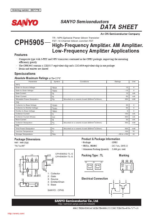
No.7177-1/860612 TKIM/62005AC MSIM TB-00001552/22802 TSIM TA-49Features• Composite type with J-FET and NPN transistors contained in the CPH5 package, improving the mounting ef fi ciency greatly• The CPH5905 contains a 2SK3357-equivalent chip and a 2SC4639-equivalent chip in one package • Drain and emitter are sharedSpeci fi cationsAbsolute Maximum Ratings at Ta=25°CParameterSymbol Conditions RatingsUnit [FET]Drain-to-Source Voltage V DSX 15V Gate-to-Drain Voltage V GDS --15V Gate Current I G 10mA Drain CurrentI D 50mA Allowable Power Dissipation P DMounted on a ceramic board (600mm 2×0.8mm)350mW [TR]Collector-to-Base Voltage V CBO 55V Collector-to-Emitter Voltage V CEO 50V Emitter-to-Base Voltage V EBO 6V Collector Current I C 150mA Collector Current (Pulse)I CP 300mA Base Current I B 30mA Collector Dissipation P CMounted on a ceramic board (600mm 2×0.8mm)350mW[TR]Total Power Dissipation P TMounted on a ceramic board (600mm 2×0.8mm)500mW Junction Temperature Tj 150°C Storage TemperatureTstg--55 to +150°CPackage Dimensionsunit : mm (typ)7017A-007CPH5905Product & Package Information• Package : CPH5• JEITA, JEDEC : SC-74A, SOT-25• Minimum Packing Quantity : 3,000 pcs./reelPacking Type : TL MarkingElectrical Connection1EL O T N o .R A N KTR : NPN Epitaxial Planar Silicon Transistor FET : N-Channel Silicon Junction FETHigh-Frequency Ampli fi er. AM Ampli fi er.Low-Frequency Ampli fi er ApplicationsElectrical Characteristicsat Ta=25°CParameterSymbolConditionsRatingsUnitmintypmax[FET]Gate-to-Drain Breakdown Voltage V (BR)GDSI G =--10μA, V GS =0V --15V Gate Cutoff Current I GSS V GS =--10V , V DS =0V --1.0nA Cutoff Voltage V GS (off)V DS =5V , I D =100μA --0.4--0.7--1.5V Drain CurrentI DSS V DS =5V , V GS =0V 10.0*32.0*mA Forward Transfer Admittance | yfs |V DS =5V , V GS =0V , f=1kHz 2435mS Input CapacitanceCiss V DS =5V , V GS =0V , f=1kHz 10.0pF Reverse Transfer Capacitance Crss V DS =5V , V GS=0V , f=1kHzz 2.9pF Noise Figure NFV DS =5V , Rg=1k Ω, I D =1mA, f=1kHz1.0dB[TR]Collector Cutoff Current I CBO V CB =35V , I E =0A 0.1μA Emitter Cutoff Current I EBO V EB =4V , I C =0A 0.1μADC Current Gain h FE V CE =6V , I C =1mA 135400Gain-Bandwidth Product f T V CE =6V , I C =10mA 200MHz Output CapacitanceCob V CB =6V , f=1MHz 1.7pF Collector-to-Emitter Saturation Voltage V CE (sat)I C =50mA, I B =5mA 0.080.4mV Base-to-Emitter Saturation Voltage V BE (sat)I C =50mA, I B =5mA 0.81.0V Collector-to-Base Breakdown Voltage V (BR)CBO I C =10μA, I E =0A 55V Collector-to-Emitter Breakdown Voltage V (BR)CEO I C =1mA, R BE =∞50V Emitter-to-Base Breakdown Voltage V (BR)EBO I E =10μA, I C =0A6V Turn-On Time t on See speci fi ed Test Circuit.0.15ns Storage Time t stg 0.75ns Fall Timet f0.20ns * : The CPH5905 is classi fied by I DSS as follows : (unit : mA)RankGHI DSS10.0 to 20.016.0 to 32.0The speci fi cations shown above are for each individual FET or transistor.Switching Time Test CircuitOrdering InformationDevicePackage Shipping memo CPH5905G-TL-E CPH53,000pcs./reel Pb FreeCPH5905H-TL-ECPH53,000pcs./reelV CC =20VV BE = --5V10I B1= --10I B2=I C =10mAI -- V ITR02749I-- V 0ITR02750Drain-to-Source V oltage, V DS -- VDrain-to-Source V oltage, V DS -- VD r a i n C u r r e n t , I D -- m AD r a i n C u r r e n t , I D -- m A[FET][FET]IT04227IT04228101.0 1.01010Drain Current, I DSS -- mAC u t o f f V o l t a g e , V G S (o f f ) -- VDrain-to-Source V oltage, V DS -- VI n p u t C a p a c i t a n c e , C i s s -- p FIT04224ITR02752Gate-to-Source V oltage, V GS -- VD r a i n C u r r e n t , I D -- m AGate-to-Source V oltage, V GS -- VD r a i n C u r r e n t , I D -- m AIT04225IT0422610 1.0101010100Drain Current, I D -- mAF o r w a r d T r a n s f e r A d m i t t a n c e , | y f s | -- m SDrain Current, I DSS -- mAF o r w a r d T r a n s f e r A d m i t t a n c e , | y f s | -- m SIT04229ITR02758101.0101.00.010.11.010100Drain-to-Source V oltage, V DS -- VR e v e r s e T r a n s f e r C a p a c i t a n c e , C r s s -- p FFrequency, f -- kHzN o i s e F i g u r e , N F -- d BITR10376ITR10377121064821001000ITR10379ITR10378Collector-to-Emitter V oltage, V CE -- VC o l l e c t o r C u r r e n t , I C -- m ACollector-to-Emitter V oltage, V CE -- VC o l l e c t o r C u r r e n t , I C -- m ABase-to-Emitter V oltage, V BE -- VC o l l e c t o r C u r r e n t , I C -- m ACollector Current, I C -- mAD C C u r r e n t G a i n , h F EITR02759IT098660.11.0101001000Signal Source Resistance, Rg -- k ΩN o i s e F i g u r e , N F -- d BAmbient Temperature, Ta -- °CA l l o w a b l e P o w e r D i s s i p a t i o n , P D -- m W[FET][FET]1001.0101001.010 1.010ITR10380ITR10381Collector Current, I C -- mAG a i n -B a n d w i d t h P r o d u c t , f T -- M H zEmitter-to-Base V oltage, V EB -- VI n p u t C a p a c i t a n c e , C i b -- pFIT098671.0101001.010ITR10384[TR][TR]101.0 1.010100ITR103821.0101000.11.0ITR10383Collector-to-Base V oltage, V CB -- VO u t p u t C a p a c i t a n c e , C o b -- p FCollector Current, I C -- mAC o l l e c t o r -t o -E m i t t e r S a t u r a t i o n V o l t a g e , V C E (s a t ) -- VCollector Current, I C -- mAB a s e -t o -E m i t t e r S a t u r a t i o n V o l t a g e , V B E (s a t ) -- VAmbient Temperature, Ta -- °CC o l l e c t o rD i s s i p a t i o n , P C -- m WEmbossed Taping Specifi cationCPH5905G-TL-E, CPH5905H-TL-EOutline Drawing Land Pattern Example CPH5905G-TL-E, CPH5905H-TL-EThis catalog provides information as of June, 2012. Specifi cations and information herein are subject to change without notice.分销商库存信息:ONSEMICPH5905G-TL-E CPH5905H-TL-E。
电子元器件型号对应表
电子元器件型号对应表741 运算放大器2063A JRC杜比降噪20730 双功放24C01AIPB21 存储器27256 256K-EPROM27512 512K-EPROM2SK212 显示屏照明3132V 32V三端稳压3415D 双运放3782M 音频功放4013 双D触发器4017 十进制计数器/脉冲分配器4021 游戏机手柄4046 锁相环电路4067 16通道模拟多路开关4069 游戏机手柄4093 四2输入施密特触发器409841256 动态存储器52432-01 可编程延时电路56A245 开关电源5G0401 声控IC5G673 八位触摸互锁开关5G673 触摸调光5G673 电子开关6116 静态RAM6164 静态RAM65840 单片数码卡拉OK变调处理器7107 数字万用表A/D转换器74123 单稳多谐振荡器74164 移位寄存器7474 双D触发器7493 16分频计数器74HC04 六反相器74HC157 微机接口74HC405374HCU04 六反相器74LS00 与门74LS00 4*2与非门74LS00 四2与非门74LS00 与门74LS04 6*1非门74LS08 4*2与门74LS11 三与门74LS123 双单稳多谐振荡器74LS123 双单稳多谐振荡器74LS138 三~二译码器74LS142 十进制计数器/脉冲分配器74LS154 4-16线译码器74LS157 四与或门74LS161 四2计数器74LS161 十六进制同步计数器74LS161 四~二计数器74LS164 数码管驱动74LS18 射频调制器74LS193 加/减计数器74LS193 四2进制计数器74LS194 双向移位寄存器74LS27 4*2或非门74LS32 四或门74LS32 4*2或门74LS374 八位D触发器74LS374 三态同相八D触发器74LS37774LS48 7位LED驱动74LS73 双J-K触发器74LS74 双D触发器74LS85 四位比较器74LS90 计数器75140 线路接收器75141 线路接收器75142A 线路接收器75143A 线路接收器7555 时钟发生器79MG 四端负稳压器8051 空调单片机8338 六反相器A1011 降噪ACVP2205-26 梳状滤波视频处理AD536 专用运放AD558 双极型8位D-A(含基准电压)变换器AD558 双极型8位D-A(含基准电压)变换器AD574A 12比特A/D变换器AD650AD670 8比特A/D变换器(单电源)1995s-2、15 AD7523 D-A变换器1994x-125AD7524 D-A变换器1994x-126AD7533 模数转换器1994x-141AD7533 模数转换器1995s-184ADC0804 8比特A/D变换器1995s-2、20 ADC0809 8CH8比特A/D 1995s-2、23ADC0833 A/D变换4路转换器1995s-2 ADC80 12比特A/D变换器1995s-2、8 ADC84/85 高速12比特A/D变换器1995s-2 AG101 手掌游戏机1993x-155AM6081 双极型8位D-A变换器1994x-127 AMP1200 音频功放皇后1993s-104AN115 立体声解码1991-135AN2510S 摄象机寻象器1994x-109AN2661NK 影碟机视频1995s-45AN2662K 时基校正(模拟)1995s-45AN2664FBP 影碟机视频1995s-45AN2664NK 影碟机视频1995s-45AN2870 影碟机伺服1995s-45AN3100N 射频调制器1991-55AN362 立体声解码1991-135AN363N 立体声解码1991-135AN3890FBS 影碟机主轴电机驱动1995s-45AN3891FBP 影碟机主轴电机驱动1995s-45 AN5026K 红外接收1993x-106AN51354 中放/音频/视频解调1994s-255 AN5138K 图象通道1994-308AN5265 音频功放1994s-298AN5342K 亮度锐度加强电路1994s-243 AN5344FBP CFU地1995s-274AN5352 模拟开关1994-245AN5515 彩电场输出1995s-34AN5515 场输出1994-73AN5521 场输出电路1991-203AN5521 场输出1994-73AN5521 场输出1994-240AN5521 场扫描1994-308AN5600K 图象处理1994-308AN5612 色差解调1994s-245AN5652 伴音中放1994-308AN5862K PIP切换输出1994s-245AN6551 双运放1991-54AN6612 电机稳速1992-63AN6612S 杜比降噪1995s-43AN6650 电机稳速1991-183AN6650 电机稳速1992-7AN6650 电机稳速1992-83AN6650 电机稳速1992-127AN6650 电机稳速1993s-165 AN6913L 双运放1995s-85AN7106K 单片放音机1992-63 AN7108 单片放音机1992-7AN7108 单片放音机1992-127 AN7108 单片放音机1992-136 AN7108 单片放音机1993s-165 AN7110 音频功放1994x-107 AN7112E 音频功放1994s-39 AN7158N 音频功放1991-3AN7158N 音频功放1991-203 AN7168 双音频功放1991-195 AN7178 音频功放1994x-107 AN7188NK 双音频功放1992-14 AN7311 双前置放大1991-195 AN7315 双前置放大1992-99 AN7410 立体声解码1991-135 AN74LS293 1994x-93AN7812 三端稳压器1994s-299AN78N05 三端稳压器1994s-298AP500/A DC功放驱动1995s-60AP500/A 双声道DC功放驱动1995s-156 AT24C01 存储器1994x-46ATC105 充电控制1993x-191AX5212D 微机鼠标编码1994s-183BA1035B 高速运放1994x-94BA1106F 放音前置放大及功放1995s-43 BA1310 立体声解码1991-135BA1320 立体声解码1991-135BA1330 立体声解码1991-135BA1335 立体声解码1991-135BA1404 调频发射1994x-183BA3015 电风扇电脑1994s-162BA3105 电风扇电脑1994x-58BA3212N 录放前置1994-180BA328 双前置放大1991-43BA328 低噪前置1992-58BA328 双声道前置放大1995s-189BA3506 音频功放1991-139BA3822LS 5段均衡1994-180BA508 遥控电路1995s-171BA5102 音频前置1993x-108BA5102 遥控电风扇编码1995s-119BA5104 电风扇遥控1995s-183BA527 音频功放1991-168BA5302 红外接收头1995s-183BA5406 双功放1992-47BA6124 电平指示1991-31BA6209 录象机加载1991-11BA6209 主导电机驱动1994-192BA6219B 加载电机驱动1994-120BA6227 电机稳速1991-139BA6303 磁鼓控速1992-139BA6439P 主导电机驱动1994-120BA728 双运放1992-91BA7751LS 录象机音频处理1993s-84 BA8105 遥控电风扇电路1995s-119BA8206A4 电风扇控制1995s-183BAS3108T FM发射1992-94BGJ3302 四运放电压比较器1994-25 BH-SK-I 声控IC 1994s-175BH-SK-V 声控IC 1994x-74BISS0001 红外传感信号处理1995s-182BL3102 时钟频率脉冲1994s-255BL3207 BBD延时1994s-255BL50462AP 遥控编码与发射1995s-299 BM5060 彩电CPU 1994-308BM5067 彩电CPU 1995s-212BM5069 彩电CPU 1995s-212BTS114 感温高速开关管1992-34BTS115 感温高速开关管1992-34BTS130 感温高速开关管1992-34BTS131 感温高速开关管1992-34BTS240 感温高速开关管1992-34BTS412 电源开关模块1992-112C036 4*2与非门1993s-93C043 双D触发器1993s-101C066C 4*2与非门1993x-147C1225H 音响驱动1992-198C1470 电机稳速1992-99C1490HA 红外接收1991-110C1676 超高频放大1995s-199C1891A 环绕声处理器1992-24C7642 单片收音机1991-95CA3069 运放1994x-184CA3160 1994x-188CA3193 音频运放1994x-36CA3524 脉冲调制1992-14CC14433 三位半A/D转换1991-46CC14433 三位半A/D转换1991-174CC4093 含施密特触发器的四2输入与非门1994s-44 CC4511 七段译码器1991-46CCU3000-17 从属微处理器1995s-299CCU3002-FDTV-11 彩电CPU 1995s-299CD1403 单运放1991-2CD4001 4*2或非门1993s-69CD4001 4*2或非门1994x-2CD4011 4*2与非门1993s-53CD4011 4*2与非门1993x-150CD4011 四2输入与非门1994s-80CD4013 双D触发器1991-2CD4013 双D触发器1993s-101CD4013 双D触发器1993x-6CD4013 双D触发器1994s-82CD4013 双D触发器1994x-22、54CD4017 十进制计数/分配1991-110CD4017 十进制计数/分配1993s-142CD4017 十进制计数译码器1994s-82CD4017 十进制计数器/脉冲分配器1994s-34 CD4017 十进制计数器/脉冲分配器1994x-2 CD40174 六D触发器1992-130CD4017B 十进制计数/分配1993x-173CD4017B 十进制计数器1995s-184CD40193B 双向可预置可逆计数器1994x-84 CD4020 14级二进制计数器1994s-80CD4024 七位二进制串行计数器1994s-80 CD4028 二~十进制译码器1992-98CD4035 移位寄存器1994s-72CD4040 十二进制二进制计数器1992-22 CD4040 十二进制二进制计数器1993s-207 CD4040 12级二进制计数器1993x-125CD4040 12级二进制计数器1994s-80CD4046 锁相环电路1994x-188CD4046 锁相环电路1995s-181CD4051 模拟开关1992-130CD4051 模拟多路转换器1995s-2、35CD4052 四选一模拟开关1992-82CD4053 3*2模拟开关1992-62、207CD4053 3*2模拟开关1994x-54CD4053 3*2模拟开关1994x-126CD4053B TV/AV切换1994-219CD4053B 双向模拟开关1994-247CD4060 分频计数1993s-12CD4060 十四位计数器/分配器/振荡器1994s-30、40 CD4066 4*2模拟开关1992-112CD4066 4*2模拟开关1993s-91CD4066BE 四路模拟开关1994-269CD4067 模拟多路转换器1992-162CD4067 模拟多路转换器1995s-2CD4069 6*1非门1991-166CD4069 6*1非门1993s-45CD4069 6*1非门1993x-150CD4069 六非门1994s-4、82CD4071 4*2或门1994s-30CD4072 2-4输入或门1992-130CD4075 三或门1991-170CD4078 多输入或门1991-170CD4093 四与非门施密特触发器1994x-42CD4099 8路可寻址锁存器1991-170CD4510 二~十加减计数器1992-98CD4511 LED显示驱动1991-2CD4511 译码驱动1993x-159CD4511 译码显示1994s-30CD4514 4-10线译码器1993x-158CD4518 双二~十进制计数器1993x-125 CD4518 计数器1994s-30CD4541B 双D触发器1995s-79CD4553 三位BCD码计数器1993s-47 CD74206 音频功放1994x-107CD9020-002 字符产生器1994s-255CD9135 六路互复位触摸开关1994x-188 CE550 电风扇控制1994s-170CH1058 音乐片1991-192CH208 译码输出1991-174CH220 电子密码锁1994x-26CIC7642 调幅收音1994s-55CIC9140 电话按键码1993s-107CNX82A2 稳压反馈光电耦合器1995s-299 CP4027 双J-K触发器1993s-109CS839 霍尔开关1994s-34CS8704 电话振铃1994-46CSC5089 单片电话机1994-77CTC9140 电话脉冲拨号1994-46CU001 多功能遥控1991-56CU47C433AN-002 彩电CPU 1994s-255 CW-18 呼救语音1993x-133CW8403 音乐IC 1993s-125CW9300 音乐IC 1993s-101CW9300 音乐IC 1993x-198CX20029 单片收音机1992-111CX20106 红外接收1993s-126CX20106 红外接收1994-230CX20106A 红外预放器1991-30CX20106A 红外接收1994x-22CX20111 调频调幅中放1992-127CX20112 电视立体声/多语种解码1994x-4 CX20188 杜比B/C降噪1992-174CX522-054 彩电CPU 1994s-302CX7959 存储器1994s-307CXA1019 单片收音机1991-114CXA1019 单片调频收音1991-152CXA1019 调频静噪1995s-52CXA1019M 单片收音机1994-74CXA1019P 单片调频收音1993x-85CXA1034P 单片放音机1992-83CXA1100 杜比降噪1991-106CXA1101 杜比降噪1991-106CXA1101 杜比降噪1992-108CXA1102 杜比降噪1991-106CXA1145P 游戏机色处理1991-131CXA1145P PAL编码1993x-78CXA1191M 调幅调频电视单片收音1993x-158 CXA1191M 单片收音机1994s-198CXA1191M 单片调频调幅收音1994x-63CXA1191P 收音专用1994-11CXA1238 单片收音机1991-140CXA1238M 调频收音1994s-130CXA1238M 调频收音1994s-156CXA1250 场频驱动1993x-103CXA1262N 单片放音机1993x-99CXA1315M 彩电副总线1995s-272CXA1642 消歌声1993s-64CXA1642 消声(卡拉OK)1995s-36CXA1642 消歌声1995s-204CXA1644P 卡拉数字延时1993x-72CXA1735S 音频处理器1995s-272CXA8008P 单片放音机1991-75CXA8008P 单片收音机1992-163CXD1254AQ 摄象机同步1993x-103CXD1310BLA 视频处理器1993x-103CXK1001P 存储器1994-307CXP80420-139S 彩电CPU 1994-334D1130 AM/FM收音1992-43D2024 音频功放1991-48D2283 音频低放1994s-135D2283 音频功放1994x-47D2822 助听器专用1991-167D414 单片收音机1991-167D7176AP 中放及伴音鉴频1994-19D7240AP 音频功放1991-3D75028CW 空调器CPU 1995s-194D7796 音频均衡1991-32DAC08 双极型8位D-A变换器1994x-129DAC08 双极型8位D-A变换器1994x-135DAC90 双极型8位D-A(含基准电压)变换器1994x-126 DBL2004 彩电场输出1995s-34DCM0016 系列高速带掉电保护RAM 1995s-174DCM0064 系列高速带掉电保护RAM 1995s-174DCM0256 系列高速带掉电保护RAM 1995s-174DCM8128 系列高速带掉电保护RAM 1995s-174 DJ2001 洗衣机电脑1991-159DN888 数字延迟1993x-110DPU-2553-25 偏转处理器1995s-299DRAM4164 数据存储1993s-80DS8629N 100分频器1992-22DTI-2260 数字瞬态改善处理器1995s-299EA1062 语音电路1994-138EK001 混频厚膜1994s-255ELM742A 低压低功耗电压比较器1995s-118 ET91210 电话程控1991-58F1212 程序快门1992-71GL7488P 录象机伺服系统1994-210GP605 开关电源PWM脉宽调制1995s-126 GS8200 录象机系统控制1994-210GSE-3568 多音声效片1994s-128GY65839 单片卡拉OK专用1994s-172GY9308 DDC数码延迟1993x-120GY9403 数码卡拉OK延迟1994x-52H9081 四声5闪光片1994x-167HA11227 立体声解码1991-135HA112A 音乐门铃1991-156HA11414 行场扫描1993s-28HA11489 亮度/彩色矩阵1991-203HA11489 视频处理1994x-19HA11509N 亮/色/行场扫描1991-43HA1166Z 黑白机行场扫描1994-82HA12017 放音均衡1991-8HA12058 杜比降噪1993x-160HA12102 双前置放大1991-43HA13001 音频功放1993s-75HA13119 音频功放1994x-99HA1392 音频功放1992-188HA1397 音频功放1991-176HA3302 四运放电压比较器1994-25HA51338SP 亮/色/行场扫描1991-43HA51338SP 彩电行场扫描/色度/亮度1995s-163 HCF40015 红外接收前置放大1994s-118HD14053B 电视遥控发射1993x-164HD401304 彩电CPU 1995s-174HD401314 彩电CPU 1995s-174HD44007A 彩色同步1991-14HEF4017 2-10进制计数器/脉冲分配器1994x-22 HEF4053BP 3*2模拟开关1994s-7HEF4066B 四路模拟开关1994-269HEF4503 3*2模拟开关1992-207HF-268/288 保密语音模块1995s-94HFC3030 彩灯闪光片1994x-71HFC3040 多发光二极管控制1991-64HFC3040 彩灯六路闪光芯片1994s-50HFC5203A 语音1994x-90HFC5219 “有电危险、请勿靠近”语音块1995s-95 HIC101 放象机电源厚膜块1995s-85HM50256 动态存储器1995s-159HM50464 动态存储器1995s-159HM511000 动态存储器1995s-159HM6117 游戏存储1993s-11HM6232 电源厚膜1993x-35HM6401 电源/场输出厚膜1991-115HM7101 电源厚膜1993x-35HM7942 电源厚膜1993x-35HM8951 电源厚膜1993s-35HM8951A 电源厚膜1995s-99HM8951B 电源厚膜1993x-195HM8951B 电源厚膜1994-65HM9007 电子镇流器1991-82HM9007 电子镇流器1993s-146HM9102 电源厚膜1992-103HM9102 电源厚膜1993x-35HM9102 开关电源取样1994-141HM9102D 电话按键码1993s-107HM911L 热释电红外线探测1994x-194 HM9201 电源厚膜1993x-35HM9205 稳压电源取样1994-332HM9207 电源厚膜1993s-3HM9207 电源厚膜1994-65HM9207B 电子镇流器1994s-6HM-JL1 音频模块1993s-160HN6401 电源厚膜1993x-35HPC177C 四运放电压比较器1994-25 HPC339C 四运放电压比较器1994-25 HT12C 遥控发射1994x-110HT2880 八音音乐片1994s-32HT6337A 风扇遥控接收1994x-110 HT7713 声控闪光片1994x-10HT7713 触摸调光1994x-63HT82D 双音音乐门铃1994s-32HY12503 可程式化语音模块1995s-94HY-20A 语音录放1994s-78HY42503 可程式化语音模块1995s-94HY-88A 动物叫声效片1993x-182HY8-S 三端音乐片1991-172IC1818P 单片游戏机1993s-95IC7107 三位半A/D转换器1993x-181ICL7107 三位半A/D驱动1993s-62ICL7107 三位半模/数转换器1994s-80ICL7107 DVM三位半A/D 1995s-2、21ICL7109 积分型12比特A/D变换器1995s-2 ICL7139 自动量程万用表1992-42ICL7660 双直流变换1993s-62ICL7660 DC-DC变换器1995s-39、68ICL8038 函数发生器1994x-112ICL8211 欠压检测用IC 1995s-40、89ICM7555 时基电路1995s-46ICM7556 时基电路1995s-40ICWJ9301 电脑密码锁1994s-190ICX045BLA 1/3寸CCD图象传感器1993x-103 IR2155 日光灯电子镇流模块1995s-38IR3M02 微机开关电源1994s-109IR3M03A DC-DC变换1992-86IR3M03A DC-DC变换1993s-119ISD1000A 系列单片语音录放IC 1995s-174 ISD1100 系列单片语音录放IC 1995s-174 ISD1400 系列单片语音录放IC 1995s-174 ISD2500 系列单片语音录放IC 1995s-174 IVR1601 一次性编程语音1993s-159IX0238CE 场输出1994-73IX0250CE 音频功放1994-73IX0256CE 开关电源1994-73IX0308 电源厚膜1992-127IX0308CZ 电源厚膜1994-67IX0323CD 电源厚膜1994s-3IX0323CE 电源厚膜1994-33IX0324CFNI 行场扫描/色解码1994-34IX0355CE 场输出1994-73IX0465CE 开关电源1994-73IX0517CE 开关电源1994-73IX0640CE 场输出1994-73IX0689CE 电源厚膜1994-48IX0711CE 彩电中放1994-73IX0711CEN 图象中放1994x-83IX0712CE 亮/色/行场扫描1994-73IX0712CEN1 扫描/解码1994-96IX0933CE 彩电CPU 1994-96JU0114 电源厚膜1991-155JU0114 彩电电源厚膜块1995s-43、51 JU0116 电源厚膜1994-66K2356 语音保密1992-178KA2184A 红外预放器1991-30KA2184A 红外线接收预放1991-56KA2184A 红外接收1993s-126KA2184A 红外接收放大1993x-170KA2209 音频功放1993x-43KA22134 音频功放1994x-83KA2221 双前置放大1991-43KA22429 调频收音1994s-55KA2402 电机稳速1993x-99KA2402 电机稳速1995s-131KA2407 电机稳速1993x-43KA2410 电话振铃1994x-11KA2410 电话振铃1994-138KA2915 单片黑白电视机1993s-167 KAC4558 双运放1991-71KD-07 闪光灯、音乐集成块1995s-71KD-100 音乐IC 1993x-5KD-152B 音乐IC 1993x-189KD-155 口哨声控片1995s-183KD-253 “叮咚”门铃1994x-194KD-253B “叮咚”门铃1994s-62KD-254 音乐片1994s-143KD482FB 石英钟报时1991-4KD-482FC 钟控打点1993s-142KD483 程控双音打点石英钟1994s-175 KD5068 狗叫声音乐片1993x-126KD5105 电子爆竹1993s-38KD-5601 爆竹声1993x-189KD56010 “恭喜发财”语音片1994x-138 KD56012 鸟叫声1993s-157KD56012 鸟叫IC 1994x-143KD-5602 军号声音乐片1995s-191KD5603 “欢迎光临”语音片1991-62KD5603 欢迎光临1993s-142KD-5603 “欢迎光临”语音片1994s-63 KD56032 六秒自然声1995s-143KD56033 娃娃哭笑语音块1995s-103 KD5604 谢谢光临1993s-142KD-5608 “狗叫”音乐片1992-168KD9300 音乐门铃1991-156KD9300 音乐门铃1994s-138KD9300 音乐门铃1994x-2、34KD9561 警车声音乐片1992-68KD9561 音乐IC 1994x-42KD9562B 警报声音乐1993x-52KD9562C 八声声效片1992-10KH1668 风扇控制1994x-154KIA6227H 音频功放1994-346KIA6299H 音频功放1994x-107KIA6401 电话振铃1994x-11KIA7299P 音频功放1994s-51KIA75558P 录象机伺服系统1994-210 KIA8125S 音频前置放大1994s-51KIA8127F AM/FM中放1994-180KM41C64P-10 画中画DRAM 1995s-299 KS5194/5 液晶显示驱动1994x-66KS5803 红外遥控发射1991-56KS5803 红外发射1992-95KS5917 语音电路1993s-183L200 五端集成稳压器1994s-110L4960 开关电源脉宽调制1995s-102 L4962 开关电源脉宽调制1995s-102 L4962 脉宽调制器1995s-152L4964 开关电源脉宽调制1995s-102 L4970 开关电源脉宽调制1995s-102 L4974 开关电源脉宽调制1995s-102 L78MR05 1994-240LA1231N FM解调1991-35LA1260 调频、调幅收音1994-104 LA3160 双前置放大1991-43LA3160 前置放大1994-340LA3350 立体声解码1991-135LA3361 立体声解码1991-66LA3361 立体声解码1991-135LA3365 立体声解码1991-135LA4127 双前置放大1993x-83LA4140 音频功放1993x-91LA4140 音频功放1994-137LA4275 音频功放1994s-255LA4422 音频功放1994-73LA4445 音频功放1991-67LA4445 音频功放1991-203LA4445 音频功放1993x-27LA4597 音频功放1993x-27LA5110 彩电稳压电源1995s-187LA5112 彩电稳压电源1995s-187LA5511 电机稳速1991-3LA5515 电机稳速1991-3LA5521D 电机稳速1995s-131LA7016 制式切换1995s-299LA7299 音频功放1991-67LA7555 中频信号处理1995s-342LA7575 PLL同步检波中频解码1995s-299LA7680 图象/伴音中频/视放/解码1994-273、302 LA7830 场输出电路1991-203LA7830 场输出电路1992-39LA7830 场输出1994-73LA7832 彩电场输出1995s-27LA7832/33 场输出1994s-255LA7837 场输出1994s-299 1995-62LA7838 场输出1994-268LA7905 50Hz/60Hz识别1994s-255LA7910 波段开关1994-248LA7920 波段开关1994s-307LAG665 单片放音机1991-132LAG665 单片放音机1991-199LAG665 单片放音机1992-47LAG665 随身听IC 1994s-20LAG665 单片放音机1994x-83LAG665F 单片放音机1993x-109LAG665F 单片立体声放音1995s-12LB1405 电平指示1993x-154LB1407 电平指示1995s-55LC219 风扇红外遥控发射1993x-170LC219 红外发射编码1994-230LC220A 六路译码器1993x-170LC220A 红外译码1994-230LC4036 双向模拟开关1994s-255LC4066B 四路模拟开关1994-269LC7441 PIP系统控制1994s-245LC7444 双时钟发生器1994s-245LC7480 多路转换开关和模/数转换器1994s-245 LC7881 D/A转换1992-124LCL102 计程显示器1994s-34LD398C 卫视接收厚膜块1993x-157LD505 音频放大1992-141LD866A 雷达探测模块1994s-63LD866B 雷达探测模块1994s-63LF398 取样与保持1995s-2、29LH-169B “抓贼呀”语音片1994s-7LIC1149-5 降压控制器1994s-104LM010 1994x-192LM1035 音量、平衡、音调直流控制1993s-32 LM1036 音量、平衡、音调直流控制1993s-32 LM1040 音量、平衡、音调直流控制1993s-32 LM12 运放1995s-30LM134 1994x-192LM1851N 漏电检测1994x-42LM1875 运算放大器1991-36LM1875 音频功放1994s-68LM1894 杜比降噪1991-106LM1894 动态降噪1991-200LM1894 降噪1993s-90LM1894 动态降噪1993s-170LM2575 开关电源脉宽调制1995s-102LM258 双前置放大1993x-43LM2904CT 三端稳压器1994s-168LM2907/2917 频率/电压转换器1994s-199LM293X 低压差三端稳压器1995s-41LM311 专用运放比较器1994x-18LM317 三端可调稳压电源1991-103LM317 三端可调稳压电源1993s-124LM317 三端可调稳压电源1994s-4LM317 正压可调三端稳压1995s-39LM317T 可调三端稳压1991-186LM318N 高速运放1994x-128LM3272C 石英钟芯1992-35LM331 V/F变换器1995s-2、37LM337 负压可调三端稳压1995s-39、46 LM339N 四运放电压比较器1994-25LM3524A 开关电源脉宽调制1995s-102 LM358 双运放1992-8LM358P 运放1995s-299LM358PS 录象机主导放大整形1994-120 LM35DZ 温度传感1992-198LM385 小功率基准电压1995s-39、60、76 LM386 音频功放1991-168LM386 音频功放1993s-6、77LM386N 音频功放1994x-90LM3875T 单片功放1993s-146LM3875T 音频功放1993x-144LM3876T 单片功放1993s-146LM389 调频发射1992-70LM3900 电流型四运放1994s-199 LM3909 单片振荡器1995s-63LM3909N 闪烁灯1995s-88LM3914 电平显示1993x-22LM3915 显示驱动1994x-16LM4280 音频功放1995s-299LM567 频率解调1991-2LM567 音频解调1991-62LM567 红外音频解调1991-134LM567 红外音频解调1994x-2LM567 红外音频解调1994x-119LM567 调频发射、接收1995s-143 LM6181 视频放大1994x-7LM723 通用型稳压块1994s-79LM833 双运放1993s-170LM8361 数字钟1994x-162LM837 四运放1993s-170LMC1982 数控音响1993s-178LP167 环形脉冲分配/驱动1994s-122LP2950CZ 低压差5V稳压器(三端)1995s-88 LQ46 四合一语音片1992-76LQ46 语音片1994x-162LR3714AM 遥控发射1993x-156LR40993 电话机发号1995s-111LR6 低压线性稳压器1995s-94LS190 对数放大器1994x-77LS7232 触摸调光1991-100LS7232 触摸调光1993s-94LS7232 触摸调光1994x-142LS85 1994x-77LT1005 逻辑控制稳压器1995s-39LT1057 音频运放1991-120LT1073 充电检测控制1994s-56LT1173CS8 DC-DC变换器1994x-8a)a 》模拟ab》地址总线accessorier》配件adc》模拟到数字的转换afc》自动频率控制agc》自动增益控制aged》模拟地afms》来自音频信号alarm》告警ant》天线antsw》天线开关atms》到移动台音频信号(b)base》三极管基极batt+》电池电压b+》内电路工作电压buzz》蜂鸣器(c)cdma》码分多址control》控制cpu》中央处理器(d)d》数字dac》数字到模拟的转换d b》数据总线dcin》外接直流电愿输入dgnd》数字地dtms》到数据信号dfms》来数据信号dsp》数字信号处理器(e)emitter》三极管发射极en》使能etacs》增强的全接入通信系统ext》外部的(f)feed back》反馈fdma》频分多址fh》跳频fl》滤波器fm》调频from》来自于(g)gain》增益gnd》地(h)hook》外接免提状态(i)i》同相支路if》中频int》中断i/o输入输出ictrl》供电电流大小控制端(l)led》发光二极管loop fliter》环路滤波器lspctrl》扬声器控制(m)mclk》主时钟mic》送话器mod》调制信号mopip》调制i信号正modin》调制i信号负mute》静音(o)ofst》偏置on》开onsrq》免提开关控制(p)powcontrol》功率控制powlev》功率级别pwrsrc》供电选择pll》锁相环q》正交支路(r)ram》随机储存器(暂存)ref》参考reset》复位rf》射频rfadat》射频频率合成数据rfaenb》射频频率合成启动rssi》接收强度指示rx》接收rxon》接收开rxifp》接收中频信号正rxifn》接收中频信号负sat-det》饱和度检测saw》声表面波滤波器spk》扬声器spi》串行外围接口swdc》末调整电压synstr》频率合成器启动synclk》频率合成器时钟syndat》频率合成器数据synton》频率合成器开/关sw》开关(t)tdma》时分多址temp》温度监测txvco》发送压控振荡器频率控制tp》测试点tx》发送tx en》发送使能txon》发送开(v)vbatt》电池电压vrpad》调整后电压vpp》峰峰值vppflash flash》编程控制vcxocont》基准振荡器频率控制vswitch》开关电压vcc》电愿vco》压控振荡第一节电阻器电阻,英文名resistance,通常缩写为R,它是导体的一种基本性质,与导体的尺寸、材料、温度有关。
CN9-SW 产品说明书
e-mail:**************User’s GuideBD9-C2, BD9-C4 (CN9 SERIES)Communications option installation guideShop online at®IntroductionThe CN9 series controllers can all be ordered or retrofitted with either an RS232 or RS485 serialcommunications interface board. If the controller has the communications interface fitted then skip to the section titled Installation/Cabling .Feature RS232 RS485Type of transmission lines UnbalancedDifferential Maximum number of drivers 1128Maximum number of receivers 1128Maximum cable length 15m 1200m Maximum data rate 19.2Kb/sec 19.2Kb/sec Maximum CMV+/- 25V+12 to -7VTable lists the features of both RS232 and RS485 standards.Cable:To ensure data integrity over long transmissiondistances, it is recommended that good quality RS485 cable is used.Recommended:RS485: Belden 9841, RS232: Belden 95012FITTING A COMMUNICATIONS INTERFACE BOARDThe RS232 and RS485 interface boards are interchangeable and are fitted in exactly the same way, please read the fitting and safety instructions before proceeding.Caution:Live circuits can hold charge for short periods after isolation from the voltage supply.Electrostatic precautions should be observed when handling the controller outside the sleeve.After isolating the controller from it’s supply, the controllerfront bezel and circuit board assembly can be unplugged from the sleeve. Grasp the bezel firmly by the recesses on each side and pull. A screwdriver can be used as a lever if required.To fit the RS232 or RS485 interface you will require the following parts, which are supplied with the interface.Insert the Nylon Bolt into the 3mm diameter hole at the bottom left hand corner of the controllers printed circuit boardPlace spacer over Nylon bolt thread.Screw the Nylon Nut onto the bolt.Do not overtighten as this will damage the screw thread.Plug the 5-way female connector on the Comms Board into the 5-way male connector on theController board ensuring that connectors are all in alignment. At the same time ensure the hole in the Comms board fits over the screw thread.Screw the Brass Nut onto the Comms board.Do not overtighten but ensure it’s tight enough to stop the board from moving.Cut the top of the screw thread so that it is level with the top of the Brass Half Nut.3Now you are ready to refit the Controller into its case. To do this carefully slide the PCB into the case aligning it with the connector arms at the rear, and then press the bezelassembly firmly into the sleeve until the latch clicks in order to compress the gasket and seal to NEMA4/IP66.Diagram 1RS485 CONNECTIONSRS485 is a half duplex serial communications link and is the standard most commonly used for industrial applications due to it’s high noise immunity and multi-drop capability. It enables a PC to communicate with up to 128 instruments over distances up to 1200 metres, and requires the addition of an RS485 interface card, or a separate RS232 / 485converter.Installation / CablingRS232 CONNECTIONSRS232 is the standard most widely used for interfacingperipherals to PC’s and is designed for serial communications with single instrument up to distances of 15 metres, in a low electrical noise environment.Connection is via a screened two core cable where thevoltage signal on each line is referenced to the screen which is grounded. Most PC’s have one or two RS232 compatible4Each RS485 interface has specific connection and termination biasing requirements which will be detailed in their installation instructions. The general principals are as follows.Terminations Because each wire is a transmission line, it must be properly terminated to prevent reflections. Where multiple instruments are daisy-chained together, a 120 ohm terminating resistor should be fitted at the connection to the PC and to the last instrument in the chain.Bias Resistors When transmission lines are not transmitting, they remain in an indeterminate state which can allow receivers to receive invalid data bits due to electrical noise on the cable. To prevent this, the lines should be forced into a known state by fitting two 620 ohm bias resistors to one point (node).If an RS485 interface card is being fitted to the PC, separate bias resistors may not be needed because they may already be fitted to the card. Check the manufacturers specification.As mentioned earlier RS485 cards and converters differ greatly in their requirements and therefore theinstallation instructions supplied with the interface should be read carefully.5Instrument 1Instrument 2Instrument ‘N’Instrument 1Instrument 2Instrument ‘N’Diagram 4 Termination resistorsDiagram 5 Bias resistorsImmediately after power-up, both instrument, and PC comms settings need to be made compatible before communication between them is possible. Instrument defaults are shown below together with available options.(Address) This is a unique identificationnumber that must be allocated to eachinstrument connected to the network.Default = 0.Options; 1 to 247(Baud rate)The setting determines the serialcommunication data transmission rate inbits/sec, and must match the PC settings.Default = 9600.Options;1200; 2400; 4800; 9600and 19200NOTE:If a comms board has been retro fittedthe default baud rate is 1200.(Data)Sets the transmission format,and must match the PC settingsData Format TableSettings Start bits Data bits Parity Stop bits Default18n (none)1 Option 118e(even)1 Option 218o (odd)1(Debug) Commissioning andtroubleshooting aid. Display shows when theinstrument is transmitting or receiving data byrapidly flashing the three horizontal segmentsof the first and last digit of the display.First digit = Tx; last digit = RxDefault = Off.Options; off; onOnly use dbuG during commissioning or trouble-shooting because it shares display segments and therefore corrupts the normal display.Instrument Comms Settings6Configuring Instrument Comms SettingsThis should also be done immediately after power-up, and is only possible from the instrument front panel.On power-up the controller will display the self test sequence followed by Alternating and nonENote: During the following procedure the display will revertto alternating and nonE after 60 seconds of keying inactivity, but will retain any settings already completed. Should this occur, or in the event of becoming‘lost’ in the program, please start again from the alternating and nonE display.To select Level C(communications settings)Press w once display alternates and 5Press and hold ✱ and press w five times to reach level C display alternates and CNote: Level C is only visible when the comms interface board is fitted to the unitTo set instrument comms addressPress v once display alternates and 0Press and hold ✱ and press v to index to chosen address number (1 to 247)Note: In the absence of any conflicting information the following comms settings should be left as the default values (see details on page 6).To read or adjust comms settingsBaud ratePress v once display alternates and 9600 (Default setting)Press and hold ✱ and use v or w keys to select preferred value.Data formatPress v once display alternates and 18n1 (Default setting)Press and hold ✱ and use v or w keys to select preferred setting. (see table page 7).Debug settingPress v once display alternates and oFF (Default setting)Press and hold ✱ and use v key to select onTo enter settings into memoryPress and hold v and w for 3 seconds display alternates and nonETo check settings; repeat the above procedureThe unit is now ready to be configured from the PC.Note:Where more than one instrument is connected to the system, it is useful at this point to list them by location, title and comms address. The list can then be used as a reference to ensure that the instruments are given the same identity when configuring the comms link from the PC.7Application SoftwareThe controllers with the communications interface fitted usethe Modbus RTU protocol. If you wish to integrate the controllers into a third party software application, or codeyour own custom software application, there is a document that explains how to communicate with the controllers. The document is available from OmegaCN9-SW APPLICATION SOFTWAREThe easiest way to communicate with the controllers is using the dedicated CN9-SW package for remote configuration and data acquisition. This package requires no programming or configuration and is ready to run, if you are familiar with Windows applications you can be up and running in minutes.CN9-SW PC REQUIREMENTSTo gain the full benefit of CN9-SW software, it is recommended that the PC is fitted with a Pentium processor, running Windows 95/98/ME/NT/2000 and has a graphics card capable of displaying a minimum of 256 colours. A minimum of 16MB RAM for Windows 95/98, 32Mb of RAM for Windows NT/ME or 64MB of RAM for Windows 2000 is recommended, together with enough free hard disk space to meet your logging requirements.CN9-SW PERFORMANCE CONSIDERATIONSWhen an application has more than 32 instruments on the bus, we recommend you look at using a higher specification PC. If you have between 32 and 128 instruments on the bus a recommended minimum PC specification would be a Pentium 200MHz processor with 64Mb of RAM. To keep CPU and RAM usage to a minimum it is generally good practice not to logdata more frequently than necessary, and also keep the timebase of charts as small as reasonably possible. If you need to review the full chart history you should select ‘View Plot’ modeand then increase the time base of the chart, remember toreturn to ‘Auto Plot’ mode when finished. If possible youshould also increase the ‘Refresh Frequency’ option in the‘Select Units To Chart’ screen. This option allows you to keep logging data in the background, but only redraw the chartwhen ‘X’ number of samples have been acquired from each controller. For instance if the ‘Sample Frequency’ is set to 1second and the ‘Refresh Frequency’ is set to 20, the chart willonly be redrawn and updated every 20 seconds, but loggingstill continues in the background at the rate of once persecond.Additional informationSETTING SECURITY LEVELS IN CN9-SWIt should be noted that functions that have been lockedappear to be still locked even when you are logged in at the correct security level. This means that the operator orsupervisor have permission to unlock and adjust functionsthey have locked, but have to unlock that function first, thenthey can adjust the function. To retain your security settings remember to re-lock any functions you have unlocked for adjustment.8Benelux:Postbus 8034, 1180 LA Amstelveen The NetherlandsTel: +31 (0)20 3472121 FAX: +31 (0)20 6434643Toll Free in Benelux: 0800 0993344e-mail:*****************Czech Republic:Rude ´arma ´d y 1868, 733 01 Karvina´ 8Tel: +420 (0)69 6311899FAX: +420 (0)69 6311114TollFree:0800-1-66342e-mail:***************France:9, rue Denis Papin, 78190 TrappesTel: +33 (0)130 621 400 FAX: +33 (0)130 699 120Toll Free in France: 0800-4-06342e-mail:**************Servicing Europe:USA and Canada:Sales Service: 1-800-826-6342/ 1-800-TC-OMEGA ®Customer Service: 1-800-622-2378/ 1-800-622-BEST ®Engineering Service: 1-800-872-9436/ 1-800-USA-WHEN ®TELEX: 996404 EASYLINK: 62968934 CABLE: OMEGAUSA: ISO 9001 Certified One Omega Drive, Box 4047Stamford CT 06907-0047Tel: (203) 359-1660FAX: (203) 359-7700e-mail:**************Servicing North America:For immediate technical or application assistance:Mexico:En Espan~ol: (001) 203-359-7803FAX: (001) 203-359-7807e-mail:*******************************.mxGermany/Austria:Daimlerstrasse 26, D-75392 Deckenpfronn, GermanyTel: +49 (0)7056 9398-0 FAX: +49 (0)7056 9398-29TollFreeinGermany************e-mail:*************United Kingdom: ISO 9002 Certified One Omega DriveRiver Bend Technology Centre Northbank, IrlamManchester M44 5BD United KingdomT el: +44 (0)161 777 6611 FAX: +44 (0)161 777 6622Toll Free in United Kingdom: 0800-488-488e-mail:**************.ukCanada:976 BergarLaval (Quebec) H7L 5A1Tel: (514) 856-6928FAX: (514) 856-6886e-mail:*************M-3835/070233081/01/0702。
- 1、下载文档前请自行甄别文档内容的完整性,平台不提供额外的编辑、内容补充、找答案等附加服务。
- 2、"仅部分预览"的文档,不可在线预览部分如存在完整性等问题,可反馈申请退款(可完整预览的文档不适用该条件!)。
- 3、如文档侵犯您的权益,请联系客服反馈,我们会尽快为您处理(人工客服工作时间:9:00-18:30)。
SW5905AC direct control IC forLED LightingDatasheetRev 0.0: Apr.17, 2014PR AnnouncementInformation provided by Silicon Works is believed to be accurate and reliable. However, no responsibility isassumed by Silicon Works for its use, nor for any infringements of patents or other rights of third parties thatmay result from its use. Specifications subject to change without notice.No license is granted by implication or otherwise under any patent or patent rights of Silicon Works. Trademarks and registered trademarks are the property of their respective owners. 707 Tamnip-dong, Yuseong-gu Daejeon, Korea 305-510Tel : 82-42-712-7700Fax: 82-42-710-7728REVISION HISTORYRev. 0.0 Apr. 17, 2014 First issuedTABLE OF CONTENTS1. FEATURES (4)2. FUNCTIONAL BLOCK DIAGRAM (5)3. PIN CONFIGURATION AND DESCRIPTIONS (6)4. ABSOLUTE MAXIMUM RATINGS (7)5. PACKAGE THERMAL CHARACTERISTICS (7)6. ELECTRICAL CHARACTERISTICS (8)7. DETAILED DESCRIPTION (9)8. APPLICATION INFORMATION (12)9. PACKAGING INFORMATION (13)1. FEATURESThe Light Emitting Diodes (LEDs) are used as indicator lamps in many devices and are increasingly used for other lighting.The SW5905 is an AC Direct driving LED controller IC. It is able to replace other lighting systems that are using AC voltage directly such as light bulb, halogen lamp and so on. It will give much convenience to the design because it requires a small number of external components. The SW5905 will help engineers to produce excellent products in LED lightings for energy efficiency, design efficiency, cost efficiency, and so on.- AC application: 85V ~ 290V range- Power: 5~10W (220V)- No inductor / no electrolytic capacitor for long life operation- Minimal external components for low system cost- Four constant current driving channels- Maximum current driving capacity of 60mA at CH4- Excellent Power Factor Correction ( > 0.9)- Automatic Power Regulation (±20%)- Protection: Over Temperature Protection (OTP)- EMI safe operation: Neither power conversion nor clock generationPACKAGE-QFN 16pin, 6mm x 6mm, 1.27mm pitch2. FUNCTIONAL BLOCK DIAGRAMFigure 1. Functional Block Diagram3. PIN CONFIGURATION AND DESCRIPTIONSFigure 2. Pin ConfigurationTable 1. Pin descriptions4. ABSOLUTE MAXIMUM RATINGSTable 2. Absolute maximum ratings5. PACKAGE THERMAL CHARACTERISTICS6. ELECTRICAL CHARACTERISTICS Table 3. Recommended Operating Conditions, T A = 25℃ unless otherwise noted7. DETAILED DESCRIPTIONPower On SequenceAs the LED lighting will replace the traditional bulbs, it should not require more control signals than those available for the bulbs. SW5905 is started by only V AC power signal. V CC is charged from 0V to V CC(ON) by V AC using internal V CC generation device. The delay time is controled by internal delay for supplied stable supply voltage and stable operation of internal block.Figure 3. Power On SequenceLED Channel Current RegulationThe SW5905 is 4-channel LED lighting driver IC that contols constant LED current regulation in order to control brightness at the LED lighting system by each channel was consist of high voltage FETs. The constant LED current regulation value can be controllable by an external resistor value using internal channel amplifier ‘s reference voltage.Figure 4. LED Channel Current RegulationVAC CompensationIf there is some amount of change in input voltage within a range of ±20%, then there is going to be same amount change in input power, because internal reference voltage is fixed no matter what input voltage is.In order to compensate the phenomena, the peak value of input voltage is sampled and compared to the standard input voltage. Then the system modulates level of channel ref voltage by the amount of the deviation of peak and standard input voltage in order to compensate input power.V AC (V)P o w e r o f L E D (W )Figure 5. VAC CompensationOver Temperature ProtectionThe junction temperature of SW5905 should not exceed the maximum limit. Over temperature protection is implemented by internal thermal shutdown circuitry, which activates at 150℃to make the LED current stops regulating immediately. Over temperature protection helps prevent catastrophic failures from accidental device overheating. Even when the junction temperature drops below 150℃, the 1-4 channel still stop the LED current regulating.8. APPLICATION INFORMATIONFigure 6. Typical Application Circuit Table 4. Recommended Component Values9. PACKAGING INFORMATIONQFN, 16 pins, 6mm x 6mm x 0.85mm, 1.27mm pitch,Figure 7. Package Dimensions。