基于单片机的多功能温度检测系统的设计翻译
基于STC单片机的温度检测系统设计

基于STC单片机的温度检测系统设计摘要该文基于STC单片机,设计了一种温度检测系统。
该系统可以对环境温度进行实时监测,并将实时温度数据显示在LCD屏幕上。
通过LM35传感器捕捉环境温度信号,并使用AD转换器将其转换成数字信号。
单片机使用定时和中断技术实时采集温度数据,并将数据存储在EEPROM中,以便后续分析和处理。
该系统具有运行稳定,实时性高等优点。
实验结果表明,该系统具有很高的精度和可靠性,具有较好的应用前景。
关键词:STC单片机、温度检测、LM35传感器、LCD显示屏1. 简介随着科技的快速发展,单片机已经越来越广泛地应用于各种物联网应用中。
温度检测系统是单片机应用的典型例子。
温度检测是工业生产、环境监测和生活中广泛应用的重要技术之一。
目前,利用单片机实现温度检测系统已经成为研究和应用领域的热点之一。
本文基于STC单片机,设计了一种温度检测系统。
该系统主要由LM35温度传感器、AD转换模块、单片机、EEPROM和LCD屏幕等部件组成。
该系统具有实时性强、运行稳定的特点,并能够对环境温度进行实时监测。
实验结果表明,该温度检测系统具有较高的精度和可靠性,具有较好的应用前景。
2. 系统设计2.1 传感器该系统采用LM35温度传感器,该传感器具有体积小、响应快、精度高等优点,是常用的温度传感器之一。
该传感器的输出电压随温度线性变化,可以轻松实现温度信号的检测。
LM35传感器输出电压与温度之间的关系式如下:Vout = (10mV/℃) T其中,Vout为输出电压,T为温度值。
2.2 AD转换模块为了将温度信号转换成数字信号,需要使用AD转换器。
该系统采用了基于STC89C52单片机的AD转换模块。
该模块可以将LM35传感器输出的模拟信号转换成单片机可以处理的数字信号。
同时,为了保证转换精度,该系统采用了连续逼近法来实现AD转换。
2.3 单片机该系统采用STC89C52单片机,该单片机具有高速、易于编程、低功耗等优点。
单片机温度控制系统论文中英文资料对照外文翻译文献

单片机温度控制系统论文中英文资料对照外文翻译文献原文题目:Single-chip microcomputer temperature control system DescriptionThe at89s52 is a low-power, high-performance CMOS 8-bit microcomputer with 4K bytes of Flash Programmable and Erasable Read Only Memory (PEROM) and 128 bytes RAM. The device is manufactured using Atmel’s high density nonvolatile memory technology and is compatible with the industry standard MCS-51™ instruction set and pinout. The chip combines a versatile 8-bit CPU with Flash on a monolithic chip, the Atmel at89s52 is a powerful microcomputer which provides a highly flexible and cost effective solution to many embedded control applications.Features:• Compatible with MCS-51™ Products• 4K Bytes of In-System Reprogrammable Flash Memory• Endurance: 1,000 Write/Erase Cycles• Fully Static Operation: 0 Hz to 24 MHz• Three-Level Program Memory Lock• 128 x 8-Bit Internal RAM• 32 Programmable I/O Lines• Two 16-Bit Timer/Counters• Six Interrupt Sources• Programmable Serial Channel• Low Power Idle and Po wer Down ModesThe at89s52 provides the following standard features: 4K bytes of Flash, 128 bytes of RAM, 32 I/O lines, two 16-bit timer/counters, a five vector two-level interrupt architecture, a full duplex serial port, on-chip oscillator and clock circuitry. In addition, the at89s52 is designed with static logic for operation down to zero frequency and supports two software selectable power saving modes. The Idle Mode stops the CPU while allowing the RAM,timer/counters, serial port and interrupt system to continue functioning. The Power Down Mode saves the RAM contents but freezes the oscillator disabling all other chip functions until the next hardware reset.Pin Description:VCC Supply voltage.GND Ground.Port 0Port 0 is an 8-bit open drain bidirectional I/O port. As an output port each pin can sink eight TTL inputs. When is are written to port 0 pins, the pins can be used as high impedance inputs.Port 0 may also be configured to be the multiplexed loworder address/data bus during accesses to external program and data memory. In this mode P0 has internal pullups.Port 0 also receives the code bytes during Flash programming, and outputs the code bytes during program verification. External pullups are required during program verification.Port 1Port 1 is an 8-bit bidirectional I/O port with internal pullups. The Port 1 output buffers can sink/source four TTL inputs. When 1s are written to Port 1 pins they are pulled high by the internal pullups and can be used as inputs. As inputs, Port 1 pins that are externally being pulled low will source current (IIL) because of the internal pullups.Port 1 also receives the low-order address bytes during Flash programming and verification.Port 2Port 2 is an 8-bit bidirectional I/O port with internal pullups. The Port 2 output buffers can sink/source four TTL inputs. When 1s are written to Port 2 pins they are pulled high by the internal pullups and can be used as inputs. As inputs, Port 2 pins that are externally being pulled low will source current (IIL) because of the internal pullups.Port 2 emits the high-order address byte during fetches from external program memory and during accesses to external data memory that use 16-bit addresses (MOVX @ DPTR). In this application it uses strong internal pull-ups when emitting 1s. During accesses to external data memory that use 8-bit addresses (MOVX @ RI), Port 2 emits the contents of the P2 Special Function Register.Port 2 also receives the high-order address bits and some control signals during Flash programming and verification.Port 3Port 3 is an 8-bit bidirectional I/O port with internal pullups. The Port 3 output buffers can sink/source four TTL inputs. When 1s are written to Port 3 pins they are pulled high by the internal pullups and can be used as inputs. As inputs, Port 3 pins that are externally being pulled low will source current (IIL) because of the pullups.Port 3 also serves the functions of various special features of the at89s52 as listed below:Port pin alternate functionsP3.0 rxd (serial input port)P3.1 txd (serial output port)P3.2 ^int0 (external interrupt0)Port 3 also receivessome control signals forFlash programming andverification. RSTReset input. A high on this pin for two machine cycles while the oscillator is runningresets the device.ALE/PROGAddress Latch Enable output pulse for latching the low byte of the address duringaccesses to external memory. This pin is also the program pulse input (PROG) during Flash programming.In normal operation ALE is emitted at a constant rate of 1/6 the oscillator frequency, and may be used for external timing or clocking purposes. Note, however, that one ALE pulse is skipped during each access to external Data Memory.If desired, ALE operation can be disabled by setting bit 0 of SFR location 8EH. With the bit set, ALE is active only during a MOVX or MOVC instruction. Otherwise, the pin is weakly pulled high. Setting the ALE-disable bit has no effect if the microcontroller is in external execution mode.PSENProgram Store Enable is the read strobe to external program memory.When the at89s52 is executing code from external program memory, PSEN is activated twice each machine cycle, except that two PSEN activations are skipped during each access to external data memory.EA/VPPExternal Access Enable. EA must be strapped to GND in order to enable the device to fetch code from external program memory locations starting at 0000H up to FFFFH. Note, however, that if lock bit 1 is programmed, EA will be internally latched on reset.EA should be strapped to VCC for internal program executions.This pin also receives the 12-volt programming enable voltage(VPP) during Flashprogramming, for parts that require 12-volt VPP.XTAL1Input to the inverting oscillator amplifier and input to the internal clock operating circuit. XTAL2Output from the inverting oscillator amplifier.Oscillator CharacteristicsXTAL1 and XTAL2 are the input and output, respectively, of an inverting amplifierwhich can be configured for use as an on-chip oscillator, as shown in Figure 1. Either a quartz crystal or ceramic resonator may be used. To drive the device from an external clock source, XTAL2 should be left unconnected while XTAL1 is driven as shown in Figure 2. There are no requirements on the duty cycle of the external clock signal, since the input to the internal clocking circuitry is through a divide-by-two flip-flop, but minimum and maximum voltage high and low time specifications must be observed. P3.3 ^int1 (external interrupt1) P3.4 t0 (timer0 external input) P3.5 t1 (timer1 external input) P3.6 ^WR (external data memory write strobe) P3.7^rd (external data memory read strobe)Idle ModeIn idle mode, the CPU puts itself to sleep while all the onchip peripherals remain active. The mode is invoked by software. The content of the on-chip RAM and all the special functions registers remain unchanged during this mode. The idle mode can be terminated by any enabled interrupt or by a hardware reset.It should be noted that when idle is terminated by a hard ware reset, the device normally resumes program execution, from where it left off, up to two machine cycles before the internal reset algorithm takes control. On-chip hardware inhibits access to internal RAM in this event, but access to the port pins is not inhibited. To eliminate the possibility of an unexpected write to a port pin when Idle is terminated by reset, the instruction following the one that invokes Idle should not be one that writes to a port pin or to external memory.Status of External Pins During Idle and Power Down Modesmode Program memory ALE ^psen Port0 Port1Port2Port3idle internal 1 1 data data data DataIdle External 1 1 float Data data Data Power down Internal 0 0 Data Data Data Data Power down External 0 0 float data Data data Power Down ModeIn the power down mode the oscillator is stopped, and the instruction that invokes power down is the last instruction executed. The on-chip RAM and Special Function Registers retain their values until the power down mode is terminated. The only exit from power down is a hardware reset. Reset redefines the SFRs but does not change the on-chip RAM. The reset should not be activated before VCC is restored to its normal operating level and must be held active long enough to allow the oscillator to restart and stabilize.Program Memory Lock BitsOn the chip are three lock bits which can be left unprogrammed (U) or can be programmed (P) to obtain the additional features listed in the table below:Lock Bit Protection ModesWhen lock bit 1 is programmed, the logic level at the EA pin is sampled and latchedduring reset. If the device is powered up without a reset, the latch initializes to a random value, and holds that value until reset is activated. It is necessary that the latched value of EA be in agreement with the current logic level at that pin in order for the device to function properly. Programming the Flash:The at89s52 is normally shipped with the on-chip Flash memory array in the erased state (that is, contents = FFH) and ready to be programmed.The programming interface accepts either a high-voltage (12-volt) or a low-voltage (VCC) program enable signal.The low voltage programming mode provides a convenient way to program the at89s52 inside the user’s system, while the high-voltage programming mode is compatible with conventional third party Flash or EPROM programmers.The at89s52 is shipped with either the high-voltage or low-voltage programming mode enabled. The respective top-side marking and device signature codes are listed in the following table.Vpp=12v Vpp=5vTop-side mark at89s52xxxxyywwat89s52xxxx-5yywwsignature (030H)=1EH(031H)=51H(032H)=FFH (030H)=1EH (031H)=51H (032H)=05HThe at89s52 code memory array is programmed byte-bybyte in either programming mode. To program any nonblank byte in the on-chip Flash Programmable and Erasable Read Only Memory, the entire memory must be erased using the Chip Erase Mode. Programming Algorithm:Before programming the at89s52, the address, data and control signals should be set up according to the Flash programming mode table and Figures 3 and 4. To program the at89s52, take the following steps.1. Input the desired memory location on the address lines.2. Input the appropriate data byte on the data lines.3. Activate the correct combination of control signals.4. Raise EA/VPP to 12V for the high-voltage programming mode.5. Pulse ALE/PROG once to program a byte in the Flash array or the lock bits. Thebyte-write cycle is self-timed and typically takes no more than 1.5 ms. Repeat steps 1 through 5, changing the address and data for the entire array or until the end of the object file is reached.Data Polling: The at89s52 features Data Polling to indicate the end of a write cycle. During a write cycle, an attempted read of the last byte written will result in the complement of the written datum on PO.7. Once the write cycle has been completed, true data are valid on all outputs, and the next cycle may begin. Data Polling may begin any time after a write cycle has been initiated.Ready/Busy: The progress of byte programming can also be monitored by theRDY/BSY output signal. P3.4 is pulled low after ALE goes high during programming to indicate BUSY. P3.4 is pulled high again when programming is done to indicate READY.Program Verify: If lock bits LB1 and LB2 have not been programmed, the programmed code data can be read back via the address and data lines for verification. The lock bits cannot be verified directly. Verification of the lock bits is achieved by observing that their features are enabled.Chip Erase: T he entire Flash Programmable and Erasable Read Only Memory array is erased electrically by using the proper combination of control signals and by holdingALE/PROG low for 10 ms. The code array is written with all “1”s. The chip erase operation must be executed before the code memory can be re-programmed.Reading the Signature Bytes: The signature bytes are read by the same procedure as a normal verification of locations 030H, 031H, and 032H, except that P3.6 and P3.7 must be pulled to a logic low. The values returned are as follows.(030H) = 1EH indicates manufactured by Atmel(031H) = 51H indicates 89C51(032H) = FFH indicates 12V programming(032H) = 05H indicates 5V programmingProgramming InterfaceEvery code byte in the Flash array can be written and the entire array can be erased by using the appropriate combination of control signals. The write operation cycle is selftimed and once initiated, will automatically time itself to completion.译文题目:单片机温度控制系统描述at89s52是美国ATMEL公司生产的低电压,高性能CMOS8位单片机,片内含4Kbytes 的快速可擦写的只读程序存储器(PEROM)和128 bytes 的随机存取数据存储器(RAM),器件采用ATMEL公司的高密度、非易失性存储技术生产,兼容标准MCS-51产品指令系统,片内置通用8位中央处理器(CPU)和flish存储单元,功能强大at89s52单片机可为您提供许多高性价比的应用场合,可灵活应用于各种控制领域。
基于单片机的温度检测系统硬件设计

基于单片机的温度检测系统硬件设计温度是工业生产和日常生活中常见的重要参数之一。
准确的温度检测对于许多应用场景至关重要,如医疗、化工、电力、食品等行业。
随着科技的不断发展,单片机作为一种集成了CPU、内存、I/O接口等多种功能于一体的微型计算机,被广泛应用于各种温度检测系统中。
本文将介绍一种基于单片机的温度检测系统硬件设计方法。
温度检测系统的主要原理是热电偶定律。
热电偶是一种测量温度的传感器,它基于塞贝克效应,将温度变化转化为电信号。
热电偶与放大器、滤波器等电路元件一起构成温度检测电路。
放大器将微弱的电信号放大,滤波器则消除噪声,提高信号质量。
将处理后的电信号输入到单片机中进行处理和显示。
在原理图设计中,我们选用了一种常见的温度检测芯片——DT-6101。
该芯片内置热电偶放大器和A/D转换器,可直接与单片机连接。
我们还选择了滤波电容、电阻等元件来优化信号质量。
原理图设计如图1所示。
软件设计是温度检测系统的核心部分。
我们采用C语言编写程序,实现温度的实时检测和显示。
程序主要分为初始化、输入处理、算法处理和输出显示四个模块。
初始化模块:主要用于初始化单片机、DT-6101等硬件设备。
输入处理模块:从DT-6101芯片读取温度电信号,并进行预处理,如滤波、放大等。
算法处理模块:实现温度计算算法,将电信号转化为温度值。
常用的算法有线性插值法、多项式拟合法等。
输出显示模块:将计算得到的温度值显示到液晶屏或LED数码管上。
硬件调试是确保温度检测系统可靠性和稳定性的关键步骤。
在组装过程中,需注意检查元件的质量和连接的正确性。
调试时,首先对硬件进行初步调试,确保各电路模块的基本功能正常;然后对软件进行调试,检查程序运行是否正确;最后进行综合调试,确保软硬件协调工作。
通过实验,我们验证了基于单片机的温度检测系统的准确性和稳定性。
实验结果表明,系统在-50℃~50℃范围内的误差小于±5℃,满足大多数应用场景的需求。
单片机温度控制系统 中英文翻译资料
单片机温度控制系统中英文翻译资料??外文翻译?? ??The General Situation of AT89C51 ??The AT89C51 is a low-power, high-performance CMOS 8-bit microcomputer with 4K bytes of Flash Programmable and Erasable Read Only Memory (PEROM) and 128 bytes RAM. The device is manufactured using Atmel’s high density nonvolatile memory technology and is compatible with the industry standard MCS-51? instruction set and pin out. The chip combines a versatile 8-bit CPU with Flash on a monolithic chip; the Atmel AT89C51 is a powerful microcomputer which provides a highly flexible and cost effective solution to many embedded control applications. ??Features: ???Compatible with MCS-51? Products ??? 4K Bytes of In-System Reprogrammable Flash Memory ??? Endurance: 1,000 Write/Erase Cycles ??? Fully Static Operation: 0 Hz to 24 MHz ??? Three-Level Program Memory Lock ??? 128 x 8-Bit Internal RAM ??? 32 Programmable I/O Lines ??? Two 16-Bit Timer/Counters ??? Six Interrupt Sources ??? Programmable Serial Channel ??? Low Power Idle and Power Down Modes ??The AT89C51 provides the following standard features: 4K bytes of Flash, 128 bytes of RAM, 32 I/O lines, two 16-bit timer/counters, a five vector two-level interrupt architecture, a full duplex serial port, on-chip oscillator and clock circuitry. In addition, the AT89C51 is designed with static logic for operation down to zero frequency and supports two software selectable power saving modes. 1 ?? ??外文翻译??The Idle Mode stops the CPU while allowing the RAM, timer/counters, serial port and interrupt system to continue functioning. The Power Down Mode saves the RAM contents but freezes the oscillator disabling all other chip functions until the next hardware reset. ?? ?? ?? ?? ?? ??Block Diagram ??Pin Description: ??VCC Supply voltage. ??GND Ground. ??Port 0:Port 0 is an 8-bit open drain bidirectional I/O port. As an output port each pin can sink eight TTL inputs. When 1s are written to port 0 pins, the pins can be used as high impedance inputs. (Sink/flow) ??Port 0 may also be configured to be the multiplexed low order address/data bus during accesses to external program and data memory. In this mode P0 has 2 ?? ??外文翻译??internal pull-ups. ??Port 0 also receives the code bytes during Flashprogramming, and outputs the code bytes during program verification. External pull-ups are required during program verification. ??Port 1:Port 1 is an 8-bit bidirectional I/O port with internal pull-ups. The Port 1 output buffers can sink/source four TTL inputs. When 1s are written to Port 1 pins they are pulled high by the internal pull-ups and can be used as inputs. As inputs, Port 1 pins that are externally being pulled low will source current (IIL) because of the internal pull-ups. ??Port 1 also receives the low-order address bytes during Flash programming and verification. ??Port 2:Port 2 is an 8-bit bidirectional I/O port with internal pull-ups. The Port 2 output buffers can sink/source four TTL inputs. When 1s are written to Port 2 pins they are pulled high by the internal pull-ups and can be used as inputs. As inputs, Port 2 pins that are externally being pulled lowinternal pull-ups. ??Port 2 emits the high-order address byte during fetches from external program memory and during accesses to external data memory that uses 16-bit addresses (MOVX @ DPTR). In this application it uses strong internal pull-ups when emitting 1s. During accesses to external data memories that use 8-bit addresses (MOVX @ RI), Port 2 emits the contents of the P2 Special Function Register. ??Port 2 also receives the high-order address bits and some control signals during Flash programming and verification. ??Port 3:Port 3 is an 8-bit bidirectional I/O port with internal pull-ups. The Port 3 output buffers can sink/source four TTL inputs. When 1s are written to Port 3 pins they are pulled high by the internal pull-ups and can be used as inputs. As inputs, Port 3 pins that are externally being pulled lowpull-ups. ??3 ?? ??外文翻译??Port 3 also serves the functions of various special features of the AT89C51 as listed below: ?? ??Port 3 also receives some control signals for Flash programming and verification. ??RST:Reset input. A high on this pin for two machine cycles while the oscillator is running resets the device. ??ALE/PROG:Address Latch Enable output pulse for latching the low byte of the address during accesses to external memory. This pin is also the program pulse input (PROG) during Flash programming. ??In normal operation ALE is emitted at a constant rate of 1/6 the oscillator frequency, and may be used for external timing or clocking purposes. Note, however, that one ALE pulse is skipped during each access to external Data Memory. ??If desired, ALE operationcan be disabled by setting bit 0 of SFR location 8EH. With the bit set, ALE is active only during a MOVX or MOVC instruction. Otherwise, the pin is weakly pulled high. Setting the ALE-disable bit has no effect if the microcontroller is in external execution mode. ??PSEN:Program Store Enable is the read strobe to external program memory. When the AT89C51 is executing code from external program memory, PSEN is activated twice each machine cycle, except that two PSEN activations are skipped during each access to external data memory. ?? ?? ?? ?? ?? ??4 ?? ??外文翻译??EA/VPP:External Access Enable. EA must be strapped to GND in order to enable the device to fetch code from external program memory locations starting at 0000H up to FFFFH. Note, however, that if lock bit 1(LB1) is programmed, EA will be internally latched(fasten with a latch) on reset. ??EA should be strapped to VCC for internal program executions. ??This pin also receives the 12-volt programming enable voltage ??should not be one that writes to a port pin or to external memory. ?? ?? ?? ?? ?? ?? ??Power Down Mode ??In the power down mode the oscillator is stopped, and the instruction that invokes power down is ?? ?? ?? ?? ?? ??the last instruction executed. The on-chip RAM and Special Function Registers retain their values until the power down mode is terminated. The only exit from power down is a hardware reset. Reset redefines the SFRs but does not change the on-chip RAM. The reset should not be activated before VCC is restored to its normal operating level and must be held active long enough to allow the oscillator to restart and stabilize. ??Program Memory LockBits ??On the chip are three lock bits which can be left unprogrammed (U) or can be programmed (P) to obtain the additional features listed in the table below: ??When lock bit 1 is programmed, the logic level at the EA pin is sampled and latched during reset. If the device is powered up without a reset, the latch initializes to a random value, and holds that value until reset is activated. It is ?? ??6 ?? ??外文翻译??necessary that the latched value of EA be in agreement with the current logic level at that pin in order for the device to function properly. ??Programming the Flash:The AT89C51 is normally shipped with the on-chip Flash memory array in the erased state (that is, contents = FFH) and ready to be programmed. The programming interface accepts either a high-voltage (12-volt) or a low-voltage (VCC) programenable signal. The low voltage programming mode provides a convenient way to program the AT89C51 inside the user’s system, while the high-voltage programming mode is compatible with conventional third party Flash or EPROM programmers. ??The AT89C51 is shipped with either the high-voltage or low-voltage programming mode enabled. The respective top-side marking and device signature ?? ?? ?? ?? ?? ??The AT89C51 code memory array is programmed byte-bybyte in either programming mode. To program any nonblank byte in the on-chip Flash Programmable and Erasable Read Only Memory, the entire memory must be erased using the Chip Erase Mode. ??Programming Algorithm: Before programming the AT89C51, the address, data and control signals should be set up according to the Flash programmingmode table and Figures 3 and 4. To program the AT89C51, take the following steps. ??1. Input the desired memory location on the address lines. ??2. Input the appropriate data byte on the data lines. ??3. Activate the correct combination of control signals. ??4. Raise EA/VPP to 12V for the high-voltage programming mode. ??7 ?? ??外文翻译??5. Pulse ALE/PROG once to program a byte in the Flash array or the lock bits. The byte-write cycle is self-timed and typically takes no more than ms. Repeat steps 1 through 5, changing the address and data for the entire array or until the end of the object file is reached. ??Data Polling: The AT89C51 features Data Polling to indicate the end of a write cycle. During a write cycle, an attempted read of the last byte written will result in the complement of the written datum on Once the write cycle has been completed, true data arevalid on all outputs, and the next cycle may begin. Data Polling may begin any time after a write cycle has been initiated. ??Ready/Busy: The progress of byte programming can also be monitored by the RDY/BSY output signal. is pulled low after ALE goes high during programming to indicate BUSY. is pulled high again when programming is done to indicate READY. ??Program Verify: If lock bits LB1 and LB2 have not been programmed, the programmed code data can be read back via the address and data lines for verification. The lock bits cannot be verified directly. Verification of the lock bits is achieved by observing that their features are enabled. ??Chip Erase: The entire Flash Programmable and Erasable Read Only Memory array is erased electrically by using the proper combination of control signals and by holding ALE/PROG low for 10 ms. Thecode array is written with all “1”s. The chip erase operation must be executed before the code memory can be re-programmed. ??Reading the Signature Bytes: The signature bytes are read by the same procedure as a normal verification of locations 030H, 031H, and 032H, except that and must be pulled to a logic low. The values returned are as follows. ??(030H) = 1EH indicates manufactured by Atmel ??(031H) = 51H indicates 89C51 ??(032H) = FFH indicates 12V programming ??(032H) = 05H indicates 5V programming ??8 ?? ??外文翻译??Programming Interface ??Every code byte in the Flash array can be written and the entire array can be erased by using the appropriate combination of control signals. The write operation cycle is selftimed and once initiated, will automatically timeitself to completion. ??9 ?? ??单片机温度控制系统中英文翻译资料??AT89C51的概况??AT89C51是美国ATMEL公司生产的低电压,高性能CMOS8位单片机,片内含4Kbytes 的快速可擦写的只读程序存储器和128 bytes 的随机存取数据存储器,器件采用ATMEL公司的高密度、非易失性存储技术生产,兼容标准MCS-51产品指令系统,片内置通用8位中央处理器和flish 存储单元,功能强大AT89C51单片机可为您提供许多高性价比的应用场合,可灵活应用于各种控制领域。
基于单片机的温度控制外文文献及中文翻译
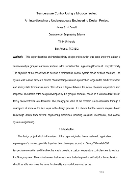
Temperature Control Using a Microcontroller:An Interdisciplinary Undergraduate Engineering Design ProjectJames S. McDonaldDepartment of Engineering ScienceTrinity UniversitySan Antonio, TX 78212Abstract:This paper describes an interdisciplinary design project which was done under the author' s supervision by a group of four senior students in the Department of Engineering Science at Trinity University. The objective of the project was to develop a temperature control system for an air-filled chamber. The system was to allow entry of a desired chamber temperature in a prescribed range and to exhibit overshoot and steady-state temperature error of less than 1 degree Kelvin in the actual chamber temperature step response. The details of the design developed by this group of students, based on a Motorola MC68HC05 family microcontroller, are described. The pedagogical value of the problem is also discussed through a description of some of the key steps in the design process .It is shown that the solution requires broad knowledge drawn from several engineering disciplines including electrical, mechanical, and control systems engineering.1 IntroductionThe design project which is the subject of this paper originated from a real-world application.A prototype of a microscope slide dryer had been developed around an OmegaTM model -390 temperature controller, and the objective was to develop a custom temperature control system to replace the Omega system. The motivation was that a custom controller targeted specifically for the application should be able to achieve the same functionality at a much lower cost, as theOmega system is unnecessarily versatile and equipped to handle a wide variety of applications.The mechanical layout of the slide dryer prototype is shown in Figure 1. The main element of the dryer is a large, insulated, air-filled chamber in which microscope slides, each with a tissue sample encased in paraffin, can be set on caddies. In order that the paraffin maintain the proper consistency, the temperature in the slide chamber must be maintained at a desired (constant) temperature. A second chamber (the electronics enclosure) houses a resistive heater and the temperature controller, and a fan mounted on the end of the dryer blows air across the heater, carrying heat into the slide chamber. This design project was carried out during academic year 1996 一97 by four students under the author5 s supervision as a Senior Design project in the Department of Engineering Science at Trinity University. The purpose of this paper is to describe the problem and the students5 solution in some detail, and to discuss some of the pedagogical opportunities offered by an interdisciplinary design project of this type. The students' own report was presented at the 1997 National Conference on Undergraduate Research [1]. Section 2 gives a more detailed statement of the problem, including performance specifications, and Section 3 describes the students, design. Section 4 makes up the bulk of the paper, and discusses in some detail several aspects of the design process which offer unique pedagogical opportunities. Finally, Section 5 offers some conclusions.2 Problem StatementThe basic idea of the project is to replace the relevant parts of the functionality of an Omega -390 temperature controller using a custom-designed system. The application dictates that temperature settings are usually kept constant for long periods of time, but if s nonetheless important that step changes be tracked in a “reasonable” manner. Thus the main requirements boil down to• allowing a chamber temperature set-point to be entered,• displaying both set-point and actual temperatures, and• tracking step changes in set-point temperature with acceptable rise time, steady-state error, and overshoot.Top ViewFront View10.25” 6.25” Figure 1. Slide diyer ineclicmical layouiAlthough not explicitly a part of the specifications in Table 1, it was clear that the customer desired digital displays of set-point and actual temperatures, and that set-point temperature entry should be digital as well (as opposed to, say, through a potentiometer setting).3 System DesignThe requirements for digital temperature displays and setpoint entry alone are enough to dictate that a microcontrollerbased design is likely the most appropriate・ Figure 2 shows a block diagram of the students5 design.Figure 2. Temperature controller hardwcuv block diagramThe microcontroller, a MotorolaMC68HC705B16 (6805 for short), is the heart of the system. It accepts inputs from a simple four-key keypad which allow specification of the set-point temperature, and it displays both set-point and measured chamber temperatures using two-digit seven-segment LED displays controlled by a display driver. All these inputs and outputs are acmodated by parallel ports on the 6805. Chamber temperature is sensed using a pre-calibrated thermistor and input via one of the 6805' s analog-to-digital inputs. Finally, a pulse-width modulation (PWM) output on the 6805 is used to drive a relay which switches line power to the resistive heater off and on.Figure 3 shows a more detailed schematic of the electronics and their interfacing to the 6805. The keypad, a Storm 3K041103, has four keys which are interfaced to pins PA0{ PA3 of Port A, configured as inputs. One key functions as a mode switch. Two modes are sup ported: set mode and run mode. In set mode two of the other keys are used to specify the set-point temperature: one increments it and one decrements. The fourth key is unused at present. The LED displays aredriven by a Harris Semiconductor ICM7212 display driver interfaced to pins PB0IPB6 of Port B, configured as outputs. The temperature-sensing thermistor drives, through a voltage divider, pin ANO (one of eight analog inputs). Finally, pin PLMA (one of two PWM outputs) drives the heater relay.Figure 3. Schematic ofinicrocontroUer boardSoftware on the 6805 implements the temperature control algorithm, maintains the temperature displays, and alters the set-point in response to keypad inputs. Because it is not plete at this writing, software will not be discussed in detail in this paper. The control algorithm in particular has not been determined, but it is likely to be a simple proportional controller and certainly not more plex than a PID. Some control design issues will be discussed in Section 4,however.4 The Design ProcessAlthough essentially the project is just to build a thermostat, it presents many nice pedagogical opportunities. The knowledge and experience base of a senior engineering undergraduate are just enough to bring him or her to the brink of a solution to various aspects of the problem. Yet, in each case, realworld considerations plicate the situation significantly.Fortunately these plications are not insurmountable, and the result is a very beneficial design experience. The remainder of this section looks at a few aspects of the problem which present the type of learning opportunity just described. Section 4.1 discusses some of the features of a simplified mathematical model of the thermal properties of the system and how it can be easily validated experimentally. Section 4.2 describes how realistic control algorithm designs can be arrived at using introductory concepts in control design. Section 4.3 points out some important deficiencies of such a simplified modeling/control design process and how they can be overe through simulation. Finally, Section 4.4 gives an overview of some of the microcontroller-related design issues which arise and learning opportunities offered.4.1 MathematicalModelLumped-element thermal systems are described in almost any introductory linear control systems text, and just this sort of model is applicable to the slide dryer problem. Figure 4 shows a second-order lumped-element thermal model of the slide dryer. The state variables are the temperatures Ta of the air in the box and Tb of the box itself. The inputs to the system are the power output q(t) of the heater and the ambient temperature T¥. ma and mb are the masses of the air and the box, respectively, and Ca and Cb their specific heats. p1 and JJ2 are heat transfercoefficients from the air to the box and from the box to the external world, respectively.If s not hard to show that the (linearized) state equationscorresponding to Figure 4 are 〃皿方 - 〃坊-“1(爲r — Tb) (1) “1(爲一 Tb) _ 'Tb — TJ (2) Taking Laplace transforms of (1) and (2) and solving for Ta(s), which is the output of interest, gives the following open-loop model of the thermal system:加)•K(x z s + 1) 1 Twhere K is a constant and D(s) is a second-order polynomial.K, tz, and the coefficients of D(s) are functions of the variousparameters appearing in (1) and (2).Of course the various parameters in (1) and(2) are pletely unknown, but if s not hard to show that, regardless of their values, D(s) has two real zeros. Therefore the main transfer function of interest (which is the one from Q(s), since we J II assume constant ambient temperature) can be written_ 爲⑸ _ Kg+ 1)力 W (^15+1)(^25 4- 1)Moreover, it' s not too hard to show that 1 =tp1 <1=tz <1 =tp2, i.e., that the zero lies between the two poles. Both of these are excellent exercises for the student, and the result is the openloop pole-zero diagram of Figure 5.q ⑴Figure 4. Luinped-elemeiu the/刀modelaqObtaining a plete thermal model, then, is reduced to identifying the constant K and the three unknown time constants in (3). Four unknown parameters is quite a few, but simple experiments show that 1=tp1 _ Utz; 1=tp2 so that tz;tp2 _ 0 are good approximations. Thus the open-loop system is essentially first-order and can therefore be writtenK%($)- ⑷(where the subscript p1 has been dropped).Simple open-loop step response experiments show that,for a wide range of initial temperatures and heat inputs, K _0:14 _=W and t _ 295 s.14.2 Control System DesignUsing the first-order model of (4) for the open-loop transfer function Gaq(s) and assuming for the moment that linear control of the heater power output q(t) is possible, the block diagram of Figure 6 represents the closed-loop system. Td(s) is the desired, or set-point, temperature,C(s) is the pensator transfer function, and Q(s) is the heater output in watts.Given this simple situation, introductory linear control design tools such as the root locus method can be used to arrive at a C(s) which meets the step response requirements on rise time, steady-state error, and overshoot specified in Table 1 .The upshot, of course, is that a proportional controller with sufficient gain can meet all specifications. Overshoot is impossible, and increasing gains decreases both steady-state error and rise time.Unfortunately, sufficient gain to meet the specifications may require larger heat outputs than the heater is capable of producing. This was indeed the case for this system, and the result is that the rise time specification cannot be met. It is quite revealing to the student how useful such an oversimplified model, carefully arrived at, can be in determining overall performance limitations.4.3 Simulation ModelGross performance and its limitations can be determined using the simplified model of Figure 6, but there are a number of other aspects of the closed-loop system whose effects on performance are not so simply modeled. Chief among these are• quantization error in analog -to-digital conversion of the measured temperature and-the use of PWM to control the heater.Both of these are nonlinear and time-varying effects, and the only practical way to study them is through simulation (or experiment, of course).Figure 7 shows a SimulinkTM block diagram of the closed-loop system which incorporates these effects. A/D converter quantization and saturation are modeled using standard Simulink quantizer乙(s)Figure 6. Simplified block diagram of the closed-loop systemand saturation blocks. Modeling PWM is more plicated and requires a custom S-function to represent it.Figure 7. Siimilink block diagram of closed-loop systemThis simulation model has proven particularly useful in gauging the effects of varying the basic PWM parameters and hence selecting them appropriately. (I.e., the longer the period, the larger the temperature error PWM introduces. On the other hand, a long period is desirable to avoid excessive relay “chatter,” among other things.) PWM is often difficult for students to grasp, and the simulation model allows an exploration of its operation and effects which is quite revealing.4.4 The MicrocontrollerSimple closed-loop control, keypad reading, and display control are some of the classic applications of microcontrollers, and this project incorporates all three. It is therefore an excellent all-around exercise in microcontroller applications. In addition, because the project is to produce an actual packaged prototype, it won, t doto use a simple evaluation board with the I/O pins jumpered to the target system. Instead, if s necessary to develop a plete embedded application. This entails the choice of an appropriate part from the broad range offered in a typical microcontroller family and learning to use a fairly sophisticated development environment. Finally, a custom printed-circuit board for the microcontroller and peripherals must be designed and fabricated.Microcontroller Selection. In view of existing local expertise, the Motorola line of microcontrollers was chosen for this project. Still, this does not narrow the choice down much. A fairly disciplined study of system requirements is necessary to specify which microcontroller, out of scores of variants, is required for the job. This is difficult for students, as they generally lack the experience and intuition needed as wellas the perseverance to wade through manufacturers J selection guides.Part of the problem is in choosing methods for interfacing the various peripherals (e.g., what kind of display driver should be used?). A study of relevant Motorola application notes [2, 3, 4] proved very helpful in understandingwhat basic approaches are available, and what microcontroller/peripheral binations should be considered.The MC68HC705B16 was finally chosen on the basis of its availableA/D inputs and PWMoutputs as well as 24 digital I/O lines. In retrospect this is probably overkill, as only one A/D channel, one PWM channel, and 11 I/O pins are actually required (see Figure 3). The decision was made to err on the safe side because a plete development system specific to the chosen part was necessary, and the project budget did not permit a second such system to be purchased should the first prove inadequate.Microcontroller Application Development. Breadboarding of the peripheral hardware, development of microcontroller software, and final debugging and testing of a custom printed-circuit board for the microcontroller and peripherals all require a development environment of some kind. The choice of a development environment, like that of the microcontroller itself, can be bewildering and requires some faculty expertise. Motorola makes three grades of development environment ranging from simple evaluation boards (at around $100) to full-blown real-time in-circuit emulators (at more like $7500). The middle option was chosen for this project: the MMEVS, which consists of _ a platform board (which supports all 6805-family parts), _ an emulator module (specific to B-series parts), and _ a cable and target head adapter (package-specific). Overall, the system costs about $900 and provides, with some limitations, in-circuit emulation capability. It also es with the simple but sufficient software development environment RAPID [5].Students find learning to use this type of system challenging, but the experience they gain in real-world microcontroller application development greatly exceeds the typical first-course experience usingsimple evaluation boards.Printed-Circuit Board. The layout of a simple (though definitely not trivial) printed-circuit board is another practical learning opportunity presented by this project. The final board layout, with package outlines, is shown (at 50% of actual size) in Figure & The relative simplicity of the circuit makes manual placement and routing practical—in fact, it likely gives better results than automatic in an application like this—and the student is therefore exposed to fundamental issues of printed-circuit layout and basic design rules. The layout software used was the very nice package pcb,2 and the board was fabricated in-house with the aid of our staff electronics technician.Figure 8. Printed-circuit layout for imcrocoutroUer board中文时:单片机温度控制:一个跨学科的本科生工程设廿顶目JamesS.McDonald工程科学系三一大学德克萨斯州圣安东尼奥市78212摘嬰:本文所描述的是作者领导由皿个三一大学高年级学生组成的01臥进行的一个跨学科工程项目的设廿。
基于单片机的温度检测系统的设计
基于单片机的温度检测系统的设计一、引言随着科技的发展和社会的进步,温度检测在各个领域中起着至关重要的作用。
为了实现对温度变化的准确监测和控制,本文将介绍一种基于单片机的温度检测系统的设计方案。
二、系统概述本系统通过采集环境温度数据,并通过单片机进行处理和控制,实现对温度的实时监测和报警功能。
三、硬件设计3.1传感器选择在温度检测系统中,传感器是获取环境温度信息的关键部件。
本系统选择了精度高、稳定性好的数字温度传感器DS18B20作为温度采集装置。
3.2单片机选择单片机是系统的核心控制部分,负责采集传感器数据、处理数据并输出相应信号。
为了满足系统的实时性和稳定性要求,本系统选择了常用的S T M32系列单片机作为控制器。
3.3电路设计基于上述选择的传感器和单片机,我们设计了相应的电路接口和连接方式,确保传感器能够正常采集数据,并将数据传输给单片机进行处理。
四、软件设计4.1系统架构本系统采用分层架构设计,包括传感器数据采集层、数据处理层和用户界面层。
每一层都有相应的功能模块,实现温度数据的采集、处理和显示。
4.2数据采集和处理系统通过定时中断方式,周期性地读取传感器数据,并通过计算得到温度值。
采集到的数据经过滤波和校正处理后,传递给用户界面层进行显示。
4.3用户界面为了方便用户操作和监测温度变化,系统设计了简洁直观的用户界面。
用户可以通过L CD显示屏上的菜单操作,查看温度数值和设置相关参数,同时系统还具备温度报警功能。
五、系统测试与结果分析5.1硬件测试在硬件实现完毕后,进行了必要的硬件测试。
通过测量不同环境下的温度,并与实际温度进行比对,验证了系统的准确性和可靠性。
5.2软件测试系统软件的测试主要包括功能测试和性能测试。
通过模拟实际使用场景,测试了系统在不同条件下的温度检测和报警功能是否正常。
六、总结与展望本文介绍了基于单片机的温度检测系统的设计方案。
通过合理的硬件选型和软件设计,实现了对温度数据的实时监测和报警功能。
基于单片机的温度控制外文文献及中文翻译

Temperature Control Using a Microcontroller: An Interdisciplinary Undergraduate Engineering Design ProjectJames S. McDonaldDepartment of Engineering ScienceTrinity UniversitySan Antonio, TX 78212Abstract:This paper describes an interdisciplinary design project which was done under the author’s supervision by a group of four senior students in the Department of Engineering Science at Trinity University. The objective of the project was to develop a temperature control system for an air-filled chamber. The system was to allow entry of a desired chamber temperature in a prescribed range and to exhibit overshoot and steady-state temperature error of less than 1 degree Kelvin in the actual chamber temperature step response. The details of the design developed by this group of students, based on a Motorola MC68HC05 family microcontroller, are described. The pedagogical value of the problem is also discussed through a description of some of the key steps in the design process. It is shown that the solution requires broad knowledge drawn from several engineering disciplines including electrical, mechanical, and control systems engineering.1 IntroductionThe design project which is the subject of this paper originated from a real-world application.A prototype of a microscope slide dryer had been developed around an OmegaTM modelCN-390 temperature controller, and the objective was to develop a custom temperature control system to replace the Omega system. The motivation was that a custom controller targeted specifically for the application should be able to achieve the same functionality at a much lower cost, as the Omega system is unnecessarily versatile and equipped to handle a wide variety of applications.The mechanical layout of the slide dryer prototype is shown in Figure 1. The main element of the dryer is a large, insulated, air-filled chamber in which microscope slides, each with a tissue sample encased in paraffin, can be set on caddies. In order that the paraffin maintain the proper consistency, the temperature in the slide chamber must be maintained at a desired (constant) temperature. A second chamber (the electronics enclosure) houses a resistive heater and the temperature controller, and a fan mounted on the end of the dryer blows air across the heater, carrying heat into the slide chamber. This design project was carried out during academic year 1996–97 by four students under the author’s supervision as a Senior Design project in the Department of Engineering Science at Trinity University. The purpose of this paper isto describe the problem and the students’ solution in some detail, and to discuss some of the pedagogical opportunities offered by an interdisciplinary design project of this type. The students’ own report was presented at the 1997 Nat ional Conference on Undergraduate Research [1]. Section 2 gives a more detailed statement of the problem, including performance specifications, and Section 3 describes the students’ design. Section 4 makes up the bulk of the paper, and discusses in some detail several aspects of the design process which offer unique pedagogical opportunities. Finally, Section 5 offers some conclusions.2 Problem StatementThe basic idea of the project is to replace the relevant parts of the functionality of an Omega CN-390 temperature controller using a custom-designed system. The application dictates that temperature settings are usually kept constant for long periods of time, but it’s nonetheless important that step changes be tracked in a “reasonable” manner. Thus the mai n requirements boil down to·allowing a chamber temperature set-point to be entered,·displaying both set-point and actual temperatures, and·tracking step changes in set-point temperature with acceptable rise time, steady-state error, and overshoot.Although not explicitly a part of the specifications in Table 1, it was clear that the customer desired digital displays of set-point and actual temperatures, and that set-point temperature entry should be digital as well (as opposed to, say, through a potentiometer setting).3 System DesignThe requirements for digital temperature displays and setpoint entry alone are enough to dictate that a microcontrollerbased design is likely the most appropriate. Figure 2 shows a block diagram of the students’ design.The microcontroller, a MotorolaMC68HC705B16 (6805 for short), is the heart of the system. It accepts inputs from a simple four-key keypad which allow specification of the set-point temperature, and it displays both set-point and measured chamber temperatures using two-digit seven-segment LED displays controlled by a display driver. All these inputs and outputs are accommodated by parallel ports on the 6805. Chamber temperature is sensed using apre-calibrated thermistor and input via one of the 6805’s an alog-to-digital inputs. Finally, a pulse-width modulation (PWM) output on the 6805 is used to drive a relay which switches line power to the resistive heater off and on.Figure 3 shows a more detailed schematic of the electronics and their interfacing to the 6805. The keypad, a Storm 3K041103, has four keys which are interfaced to pins PA0{ PA3 of Port A, configured as inputs. One key functions as a mode switch. Two modes are supported: set mode and run mode. In set mode two of the other keys are used to specify the set-point temperature: one increments it and one decrements. The fourth key is unused at present. The LED displays are driven by a Harris Semiconductor ICM7212 display driver interfaced to pins PB0{PB6 of Port B, configured as outputs. The temperature-sensing thermistor drives, through a voltage divider, pin AN0 (one of eight analog inputs). Finally, pin PLMA (one of two PWM outputs) drives the heater relay.Software on the 6805 implements the temperature control algorithm, maintains the temperature displays, and alters the set-point in response to keypad inputs. Because it is not complete at this writing, software will not be discussed in detail in this paper. The control algorithm in particular has not been determined, but it is likely to be a simple proportional controller and certainly not more complex than a PID. Some control design issues will be discussed in Section 4, however.4 The Design ProcessAlthough essentially the project is just to build a thermostat, it presents many nice pedagogical opportunities. The knowledge and experience base of a senior engineering undergraduate are just enough to bring him or her to the brink of a solution to various aspects of the problem. Yet, in each case, realworld considerations complicate the situation significantly.Fortunately these complications are not insurmountable, and the result is a very beneficial design experience. The remainder of this section looks at a few aspects of the problem which present the type of learning opportunity just described. Section 4.1 discusses some of the features of a simplified mathematical model of the thermal properties of the system and how it can beeasily validated experimentally. Section 4.2 describes how realistic control algorithm designs can be arrived at using introductory concepts in control design. Section 4.3 points out some important deficiencies of such a simplified modeling/control design process and how they can be overcome through simulation. Finally, Section 4.4 gives an overview of some of the microcontroller-related design issues which arise and learning opportunities offered.4.1 MathematicalModelLumped-element thermal systems are described in almost any introductory linear control systems text, and just this sort of model is applicable to the slide dryer problem. Figure 4 shows a second-order lumped-element thermal model of the slide dryer. The state variables are the temperatures Ta of the air in the box and Tb of the box itself. The inputs to the system are the power output q(t) of the heater and the ambient temperature T¥. ma and mb are the masses of the air and the box, respectively, and Ca and Cb their specific heats. μ1 and μ2 are heat transfer coefficients from the air to the box and from the box to the external world, respectively.It’s not hard to show that the (linearized) state equationscorresponding to Figure 4 areTaking Laplace transforms of (1) and (2) and solving for Ta(s), which is the output of interest, gives the following open-loop model of the thermal system:where K is a constant and D(s) is a second-order polynomial.K, tz, and the coefficients ofD(s) are functions of the variousparameters appearing in (1) and (2).Of course the various parameters in (1) and (2) are completely unknown, but it’s not hard to show that, reg ardless of their values, D(s) has two real zeros. Therefore the main transfer function of interest (which isthe one from Q(s), since we’ll assume constant ambient temperature) can be writtenMoreover, it’s not too hard to show that 1=tp1 <1=tz <1=tp2, i.e., that the zero lies between the two poles. Both of these are excellent exercises for the student, and the result is the openloop pole-zero diagram of Figure 5.Obtaining a complete thermal model, then, is reduced to identifying the constant K and the three unknown time constants in (3). Four unknown parameters is quite a few, but simple experiments show that 1=tp1 _ 1=tz;1=tp2 so that tz;tp2 _ 0 are good approximations. Thus the open-loop system is essentially first-order and can therefore be written(where the subscript p1 has been dropped).Simple open-loop step response experiments show that,for a wide range of initial temperatures and heat inputs, K _0:14 _=W and t _ 295 s.14.2 Control System DesignUsing the first-order model of (4) for the open-loop transfer function Gaq(s) and assuming for the moment that linear control of the heater power output q(t) is possible, the block diagram of Figure 6 represents the closed-loop system. Td(s) is the desired, or set-point, temperature,C(s) is the compensator transfer function, and Q(s) is the heater output in watts.Given this simple situation, introductory linear control design tools such as the root locus method can be used to arrive at a C(s) which meets the step response requirements on rise time, steady-state error, and overshoot specified in Table 1. The upshot, of course, is that a proportional controller with sufficient gain can meet all specifications. Overshoot is impossible, and increasing gains decreases both steady-state error and rise time.Unfortunately, sufficient gain to meet the specifications may require larger heat outputs than the heater is capable of producing. This was indeed the case for this system, and the result is that the rise time specification cannot be met. It is quite revealing to the student how useful such an oversimplified model, carefully arrived at, can be in determining overall performance limitations.4.3 Simulation ModelGross performance and its limitations can be determined using the simplified model of Figure 6, but there are a number of other aspects of the closed-loop system whose effects on performance are not so simply modeled. Chief among these are·quantization error in analog-to-digital conversion of the measured temperature and· the use of PWM to control the heater.Both of these are nonlinear and time-varying effects, and the only practical way to study them is through simulation (or experiment, of course).Figure 7 shows a SimulinkTM block diagram of the closed-loop system which incorporates these effects. A/D converter quantization and saturation are modeled using standard Simulink quantizer and saturation blocks. Modeling PWM is more complicated and requires a customS-function to represent it.This simulation model has proven particularly useful in gauging the effects of varying thebasic PWM parameters and hence selecting them appropriately. (I.e., the longer the period, the larger the temperature error PWM introduces. On the other hand, a long period is desirable to avoid excessive relay “chatter,” among other things.) PWM is often difficult for students to grasp, and the simulation model allows an exploration of its operation and effects which is quite revealing.4.4 The MicrocontrollerSimple closed-loop control, keypad reading, and display control are some of the classic applications of microcontrollers, and this project incorporates all three. It is therefore an excellent all-around exercise in microcontroller applications. In addition, because the project isto produce an actual packaged pro totype, it won’t do to use a simple evaluation board with theI/O pins jumpered to the target system. Instead, it’s necessary to develop a complete embedded application. This entails the choice of an appropriate part from the broad range offered in a typical microcontroller family and learning to use a fairly sophisticated development environment. Finally, a custom printed-circuit board for the microcontroller and peripherals must be designed and fabricated.Microcontroller Selection. In view of existing local expertise, the Motorola line of microcontrollers was chosen for this project. Still, this does not narrow the choice down much. A fairly disciplined study of system requirements is necessary to specify which microcontroller, out of scores of variants, is required for the job. This is difficult for students, as they generally lack the experience and intuition needed as well as the perseverance to wade through manufacturers’ selection guides.Part of the problem is in choosing methods for interfacing the various peripherals (e.g., what kind of display driver should be used?). A study of relevant Motorola application notes [2, 3, 4] proved very helpful in understandingwhat basic approaches are available, and what microcontroller/peripheral combinations should be considered.The MC68HC705B16 was finally chosen on the basis of its availableA/D inputs and PWMoutputs as well as 24 digital I/O lines. In retrospect this is probably overkill, as only oneA/D channel, one PWM channel, and 11 I/O pins are actually required (see Figure 3). The decision was made to err on the safe side because a complete development system specific to the chosen part was necessary, and the project budget did not permit a second such system to be purchased should the firstprove inadequate.Microcontroller Application Development. Breadboarding of the peripheral hardware, development of microcontroller software, and final debugging and testing of a customprinted-circuit board for the microcontroller and peripherals all require a development environment of some kind. The choice of a development environment, like that of themicrocontroller itself, can be bewildering and requires some faculty expertise. Motorola makes three grades of development environment ranging from simple evaluation boards (at around $100) to full-blown real-time in-circuit emulators (at more like $7500). The middle option was chosen for this project: the MMEVS, which consists of _ a platform board (which supports all 6805-family parts), _ an emulator module (specific to B-series parts), and _ a cable and target head adapter (package-specific). Overall, the system costs about $900 and provides, with some limitations, in-circuit emulation capability. It also comes with the simple but sufficient software development environment RAPID [5].Students find learning to use this type of system challenging, but the experience they gain in real-world microcontroller application development greatly exceeds the typical first-course experience using simple evaluation boards.Printed-Circuit Board. The layout of a simple (though definitely not trivial) printed-circuit board is another practical learning opportunity presented by this project. The final board layout, with package outlines, is shown (at 50% of actual size) in Figure 8. The relative simplicity of the circuit makes manual placement and routing practical—in fact, it likely gives better results than automatic in an application like this—and the student is therefore exposed to fundamental issues of printed-circuit layout and basic design rules. The layout software used was the very nice package pcb,2 and the board was fabricated in-house with the aid of our staff electronics technician.中文翻译:单片机温度控制:一个跨学科的本科生工程设计项目JamesS.McDonald工程科学系三一大学德克萨斯州圣安东尼奥市78212摘要:本文所描述的是作者领导由四个三一大学高年级学生组成的团队进行的一个跨学科工程项目的设计。
- 1、下载文档前请自行甄别文档内容的完整性,平台不提供额外的编辑、内容补充、找答案等附加服务。
- 2、"仅部分预览"的文档,不可在线预览部分如存在完整性等问题,可反馈申请退款(可完整预览的文档不适用该条件!)。
- 3、如文档侵犯您的权益,请联系客服反馈,我们会尽快为您处理(人工客服工作时间:9:00-18:30)。
基于单片机的多功能温度检测系统的设计一、引言随着社会的发展和技术的进步,人们越来越注重温度检测与显示的重要性。
温度检测与状态显示技术与设备已经普遍应用于各行各业,市场上的产品层出不穷。
温度检测及显示也逐渐采用自动化控制技术来实现监控。
本课题就是一个温度检测及状态显示的监控系统。
二、系统方案本系统采用AT89S52 作为该系统的单片机。
系统整体硬件电路包括,电源电路,传感器电路,温度显示电路,上下限报警电路等如图1 所示。
图中报警电路可以在被测温度不在上下限X围内时,发出报警鸣叫声音。
温度控制的基本原理为:当DSl8B20 采集到温度信号后,将温度信号送至AT89S52 中处理,同时将温度送到LCD 液晶屏显示,单片机根据初始化设置的温度上下限进行判断处理,即如果温度大于所设的最高温度就启动风扇降温;如果温度小于所设定的最低温度就启动报警装置。
温度控制器的原理图二三、系统硬件设计1.单片机AT89S52 的介绍AT89S52 是一种低功耗、高性能CMOS8 位微控制器,具有8K 可编Flash 存储器。
使用Atmel 公司高密度非易失性存储器技术制造,与工业80C51 产品指令和引脚完全兼容。
片上Flash 允许程序存储器在系统编程,亦适于常规编程器。
在单芯片上,拥有灵巧的8 位CPU和在系统可编程Flash,使AT89S52 为众多嵌入式控制应用系统提供高灵活、超有效的解决方案[5]。
AT89S52 具有以下标准功能:8k 字节Flash,256 字节RAM,32 位I/O 口线,看门狗定时器,2 个数据指针,三个16 位定时器/计数器,一个6 向量2 级中断结构,全双工串行口,片内晶振及时钟电路。
另外,AT89S52 可降至0Hz 静态逻辑操作,支持2 种软件可选择节电模式。
空闲模式下,CPU 停止工作,允许RAM、定时器/计数器、串口、中断继续工作。
掉电保护方式下,RAM 内容被保存,振荡器被冻结,单片机一切工作停止,直到下一个中断或硬件复位为止。
2.DS18B20 传感器的介绍在传统的模拟信号远距离温度测量系统中,需要很好的解决引线误差补偿问题、多点测量切换误差问题和放大电路零点漂移误差问题等技术问题,才能够达到较高的测量精度。
另外一般监控现场的电磁环境都非常恶劣,各种干扰信号较强,模拟温度信号容易受到干扰而产生测量误差,影响测量精度[5]。
因此,在温度测量系统中,采用抗干扰能力强的新型数字温度传感器是解决这些问题的最有效方案,与其它温度传感器相比DSl820 具有以下特点:(1)独特的单线接口方式。
DSl820 在与微处理器连接时仅需要一条接口线即可实现微处理器与DSl820 的双向通讯。
(2)多点功能简化了分布式温度检测的应用。
(3)DSl820 在使用中无需任何外围元件。
(4)可用数据线供电,电压X围从3.0V 到5.5V。
(5)可测量的温度X围从-55℃到+125℃,增量值0. 5℃;华氏温度X围从-67 到+257,增量值0.9。
(6)支持多点组网功能。
多个DS1820 可以并接在同一条总线上,实现多点测温。
(7)9 位的温度分辨率。
测量结果以9 位数字量方式串行传送。
(8)用户可设定温度报警门限值。
(9)有超温度搜寻功能。
(1)DSl8B20 的工作原理DS18B20 的内部结构DSl8B20 的测温原理框图如图3.2 所示。
图中低温度系数品振的振荡频率受温度影响很小,用于产生同定频率的脉冲信号送给计数器l。
高温度系数晶振随温度变化其振荡频率明显改变。
所产生的信号作为计数器2 的脉冲输入。
计数器1、计数器2 和温度寄存器被预置在-55℃所对应的一个基数值。
计数器l 对低温度系数晶振产生的脉冲信号进行减法计数,当计数器1 的预置值减到O 时,温度计数器的值将加l,计数器l 的预置值将被重新装人,计数器l 重新开始对低温度系数晶振产生的脉冲信号进行计数,如此循环直到计数器2 计数到O 时,停止温度寄存器的累加,此时温度寄存器中的数值即为所测温度。
图3.2 中的斜率累加器用于补偿和修正测温过程中的非线性,其输出小于修正计数器l 的预置值。
(2)DS18B20 与AT89S52 的接口方式DS18B20 与单片机的连接方式有两种:即寄生电源方式和外部电源方式。
寄生电源方式:在寄生电源供电方式下,DS18B20 从单线信号线上汲取能量:在信号线DQ 处于高电平期间把能量储存在内部电容里,在信号线处于低电平期间消耗电容上的电能工作,直到高电平到来再给寄生电源(电容)充电。
寄生电源方式有三个好处:1)进行远距离测温时,无需本地电源。
2)可以在没有常规电源的条件下读取ROM。
3)电路更加简洁,仅用一根I/O 口实现测温。
要想使DS18B20 进行精确的温度转换,I/O 线必须保证在温度转换期间提供足够的能量,由于每个DS18B20 在温度转换期间工作电流达到1mA,当几个温度传感器挂在同一根I/O 线上进行多点测温时,只靠4.7K 上拉电阻就无法提供足够的能量,会造成无法转换温度或温度误差极大。
外部电源供电方式:在外部电源供电方式下,DS18B20 工作电源由VDD 引脚接入,此时I/O 线不需要强上拉,不存在电源电流不足的问题,可以保证转换精度,同时在总线上理论可以挂接任意多个DS18B20 传感器,组成多点测温系统。
本系统采用外部电源方式。
连接方法即DS18B20 的1 脚接地,2 脚(DQ 引脚)与AT89S52 的一根I/O 口线相连,3 脚接+5V。
在A89S52 的I/O 口线与+5V 之间连接一4.7K 的上拉电阻,以保证数据采集的正常进行。
若要组成多点温度检测系统,可在单片机的同一根I/O 口线上,以相同的连接方法并联多片DS18B20 芯片。
3、LCD1602 液晶屏1602 液晶显示模块可以和单片机AT89S52 直接接口。
4、蜂鸣器驱动电路由于蜂鸣器的工作电流一般比较大,以致于单片机的I/O 口是无法直接驱动的,所以要利用放大电路来驱动,一般使用三极管来放大电流就可以了。
当所测的温度低于6 摄氏度时,报警。
5、风扇电路当所测的温度高于80 摄氏度时,启动风扇电路。
因为工作电流比较大,所以用放大电路来驱动,即用三极管来放大电流就可以了。
当温度高于80℃时,给单片机一个命令,单片机P2.6 引脚输出高电平,三极管导通,风扇电路接通,电风扇开始转动,从而起到降温作用。
四、系统的软件设计本系统采用AT89S52 作为核心处理器件,把经过DSl8B20 现场实时采集到的温度数据,存入AT89S52 的内部数据存储器,送液晶显示,并与预先设定值进行比较,然后由单片机输出信号去控制风扇电路和报警电路。
多功能温度检测显示系统软件主要包括:函数声明、延迟时间函数、DS18B20 初始化函数、读出DS18B20 当前的温度、温度数据转化成液晶字符显示等程序。
五、小结随着工业的不断发展,对温度测量的要求来越高,而且测量X围也越来越广,因此对温度检测技术的要求也越来越高。
本文介绍了以DSl8B20 新型数字温度传感器、AT89S52 单片机、LCD1602 液晶显示模块为主体构建的温度检测显示系统。
说明了系统硬件电路、系统主程序与各模块子程序的设计。
本系统采用的是DALLAS 公司推出的数字式温度传感器DS18B20,无需外加A/D 即可输出数字量,把温度信号直接转换成串行数字信号供微机处理。
因此。
该系统具有硬件电路结构简单、转换精度高、显示结果清晰稳定、成本低等显着优点。
在诸如粮库测温、智能建筑、中央空调等多种需要温度检测的场合具有较好的应用前景。
Based on SCM multi-functional temperature testingsystem design1、prefaceWith the development of society and the technological progress, people pay more and more attention to the importance of temperature detection and display. Temperature detection and status display technology and equipment has been widely applied in industries, products on the market emerge in endlessly. Temperature testing and also gradually adopt the automatic control technology to realize the monitor. This topic is a temperature testing and status of the monitoring system.2、System solutionsThis system USES the monolithic integrated circuit AT89S52 as this system. The whole system, the hardware circuit including power supply circuit, sensor, the temperature display circuit circuit, upper alarm circuit such as shown in figure 1. Figure in the alarming circuit can be measured in upper temperature range, screaming voice alarm. The basic principle for the temperature control DSl8B20: when the temperature signal acquisition to after temperature signal sent to handle, AT89S52 temperature to LCD screen, SCM according to initialize the upper temperature setting, namely, if thejudgement of temperature than the highest temperature cooling fan is started, If the temperature is less than the lowest temperature setting on alarm device. Temperature controller diagram3、The system hardware design(1)AT89S52 SCM are introducedAT89S52 devices is a low power consumption, high CMOS8 bit micro-controller, 8K programmable Flash memory. Use Atmel pany high-density nonvolatile storage technology, and industrial 80C51 product instruction and pin fully patible. The Flash memory chips allows programs in system programming, also suitable for conventional programming. In a single chip, have clever 8 bits CPU and programmable Flash in the system, for many embedded control AT89S52 application system provides a highly flexible, efficient solutions [5]. AT89S52 has the following functions: the standard 256 bytes, 8k byte Flash RAM, 32 I/O port, the watchdog timer, 2 data, three pointer 16 timer/counter, a 6 vector level 2 interrupt structure, full-duplex serial, timely clock circuit within crystals. In addition, 0Hz AT89S52 can drop to the static logic operation, support two software can choose power saving mode. Idle mode, the CPU to stop working, and allows the RAM, timer/counters, serial, continue to work. Protection mode, RAM by MCU, oscillator is frozen, all the work to stop until the next interruption or hardware reset.(2)The sensor DS18B20In the traditional analog signal distance temperature measuring system, need good solve lead error pensation, multi-point measurement error and amplifying circuitswitching technologies such as zero drift error problem, can achieve high measuring accuracy. Another general monitoring site of the electromagnetic environment is very bad, all kinds of jamming signal is stronger, the simulated temperature signal interference and vulnerable to produce measurement error and measuring precision [5]. Therefore, in temperature measuring system, the strong anti-jamming capability of the new digital temperature sensor is the most effective to solve these problems, pared with other temperature sensor DSl820 has the following features:(1) the unique singleline interface way. DSl820 in connection with the microprocessor only need one interface to implement line DSl820 microprocessors and two-way munication. (2) more function simplifies distributed temperature detection application. (3) DSl820 in use without any peripheral devices. (4) power, voltage range data available from 3.0 V to 5.5 V. (5) can measure temperature range from - 55 degrees c + + to 125, incremental value 0. 5 ° c, Fahrenheit temperature range from - 67 to + 257, incremental value 0.9. (6) support multi-point network function. Multiple DS1820 can pick on the same bus and, more temperature measurement. (7) 9 temperature resolution. Measuring results in nine serial transmission way the digital quantity. (8) user can set temperature alarm threshold. (9) have super temperature search function.①.DSl8B20 principle of workThe internal structure of DS18B20 DSl8B20 temperature measurement principle diagram shown in figure 3.2. Low temperature coefficient graph oscillation frequency vibration product temperature is used to produce with fixed frequency, pulse signal tocounter l. High temperature coefficient crystals temperature-dependent its oscillation frequency change significantly. The signal generated as the counter 2 input pulses. Counter 1, 2 and temperature registers are counter in - 55 degrees preset corresponding a base value. Counter l to low temperature coefficient of the pulse signal generated crystals, when the counter for subtraction counting the preset value reduced to 1, when the temperature counter O value will add l, counter the preset value will be l man again, to counter the l start low temperature coefficient of crystal oscillator pulse signal, so cycle count until the counter 2, stop counting to O accumulative temperature, temperature of the register for the register is measured values. Figure 3.2 accumulative used for the slope pensation and fixed temperature measurement, the output of the process of nonlinear correction is less than the preset value counter l.②.AT89S52 interface mode and DS18B20Chip DS18B20 and the connection has two kinds: namely parasitic power and external power supply mode.Parasitic power way: in the parasitic power supply mode, the signal from the single chip DS18B20 in line drawing energy during the high level in the DQ energy stored in the internal capacitance, low level in signal in the energy consumed during the capacitance on working until high-level ing again to parasitic power (battery). Parasitic power mode has three advantages: 1) distance measuring temperature, without the local power supply. 2) no conventional power in the condition reads the ROM. 3) circuit, with only one more concise root I/O realize temperature measurement. Want to make precise temperature conversion chip DS18B20, I/O line must ensure that the temperatureconversion period, due to provide enough energy conversion in temperature during each DS18B20, when the current 1mA to work a few temperature sensor in the same root hanging on the I/O multi-point temperature measurement, only by 4.7 K and resistance will not be able to provide enough energy, which cannot be switchover temperature or errors.The external power source supply way: in the external power supply modes, DS18B20 work power by VDD pin, I/O access line does not need strong pull up, there is no shortage of electricity power, can ensure accuracy and conversion in the bus theory can be articulated multiple sensor DS18B20, multipoint temperature measuring system.This system USES the external power source. Connection method is one foot grounding and DS18B20 2 feet (DQ) and AT89S52 foot an I/O port, 3 feet line up + 5V. A89S52 in the I/O port and + 5V connection between a 4.7 K pull-up resistors, to ensure the normal operation of the data collection. If you want to test system, posed multi-point temperature in the same root chip I/O port in the same line, and the method of connecting the parallel more pieces of DS18B20 chip.(3)LCD1602 LCD1602 LCD module can and monolithic integrated circuit AT89S52 directly interface. (4)Buzzer driver circuitDue to the working current buzzer is pared monly big, so I/O microcontroller is not directly driven by amplifying circuit, so it is generally used to drive, to enlarge current transistor. When the temperature is below six degrees Celsius, alarm.(5)Fan circuitWhen the temperature is higher than 80 ° c, start fan circuit. Because the job is great, so use current amplifier circuit to drive, to enlarge current transistor. When the temperature is above 80 ° c, give a mand, P2.6 single-chip microcontroller foot output level, triode conduction, fans, electric circuit, which began to turn it down.4、The design of the software systemThis system USES AT89S52 devices as the core, with DSl8B20 after the collected data, and the temperature inside the data storage AT89S52 deposit, LCD display, and pared with the prior value, and then the output signal by MCU control circuit and alarm circuit fan. Multi-functional temperature testing system software mainly include: function declarations, time delay function and DS18B20 initialization function, read the temperature, temperature DS18B20 data into a liquid crystal display characters such programs.5、SummaryWith the continuous development of industry of temperature measurement, the higher requirement, and more and more wide measuring range, so are the requirements for temperature detection technology more and more is also high.DSl8B20 introduced new digital temperature sensor and AT89S52 SCM, LCD1602 LCD module for constructing the temperature testing system. The hardware circuit and main program and system design of each module subroutines. This system USES the DALLAS is the digital temperature sensor DS18B20, plus A/D can output the digital quantity, the temperature signal directly convert serial digital signal processing for microputer. Accordingly. This system has the hardware circuit structure is simple, highprecision, and shows the result conversion clear stability, low cost and significant advantages. In temperature measurement, such as grain of intelligent building, central air conditioning of the occasion to temperature testing has good application prospects.。