HPATOOL及MSETUP使用说明
1哈普转矩流变仪及控制平台软件使用说明

哈普转矩流变仪及控制平台软件使用说明一般操作步骤•安装实验平台・通电・运行控制平台软件« 选择实验平台・选择通讯串口«启动通讯«设定工作温度及输岀转速«启动加热*启动电机4 开始实验«关闭设备一般操作步骤在流变仪安装好及在配套的计算机中安装好控制平台软件后,可以开始使用流变仪进行实验流变仪的一般使用过程可按照以下步骤进行:安装实验平台请根据实验类型或实验目的选择一种实验平台(混炼器或挤岀机),混炼器或挤岀机安装方法请参照现象调试人员的示范。
安装实验平台时,应注意热传感器及加热电源接口的连接顺序,错误的连接顺序将导致无法正确地进行温度控制。
流变仪前面板加热电源/ 一挤出机加热区顺序示意图混炼器加热区顺序示意图热传感器接口示意图通电安装好实验平台并检查无误后,打开设在流变仪主机背面的总电源开关,顺时针旋转90度至“ON为开通,逆时针旋转90度至“ OFF”为关断,当给流变仪主机通电时,电源开关左侧的电源指示灯会亮起,说明主机通电正常,可以开始工作。
流变仪主机总电源开关图运行控制平台软件当流变仪主机通电后,可以运行已经安装在计算机中的控制软件以控制流变仪进行工作。
要运行控制平台HP软件,请单击开始菜单->所有程序->转矩流变仪软件->哈普流变仪或双击桌面上的二图标运行流变仪控制平台软件。
控制平台程序界面如下图所示:控制平台软件界面图选择正确的实验平台流变仪在正常工作时,一般为主机连接一台混炼器或挤岀机进行工作,因此我们需要在控制平台上选择相应实验平台,这样软件才能以正确的方式控制流变仪进行工作。
“实验平台”一般分为混炼器平台及挤岀机平台,按照下图指示的位置在下拉列表中选择实验平台。
选择实验平台示意图混炼器平台挤出机平台注:在平台选择列表下方的8个选项中,T1-T4代表1区温度至4区温度,Tm代表料温,Tq代表扭矩,P 代表压力,Sp代表压力,分别选中或取消它们表示启动相应的测量及控制。
MEOGA pH Controller 操作手册说明书
@ Load Cells & Pressure Gauges @’ Displacement Transducers 0 Instrumentation & Accessories
FLOW/ LEVEL b? Rotameters, Gas Mass Blowmeters &
photo pan,
pH Controller Operator ’s Manual
SECTION
Section 1 Getting Started
1 .I &packing the Controller.. .......................................
1.2 Controller Description
4.1.2
To Enter the Lo Setpoint Value.. ............................... .4-l
4.2 Error Messages ..........................................................................
203-359-7807.
BEFORE RETURNtNG ANY PRODUCT(S) TO OMEGA, YOU MUST OBTAIN AN
AUTHORtZED RETURN (AR)
NUMBER FROM OUR CUSTOMER SERVICE DEPARTMENT The assigned AR number should then be marked on
Patrol3.0软件安装及使用说明

Patrol3.0软件安装及快速使用指南第一章巡检管理系统软件的安装【安装前说明】(1)将360安全卫士等其他的杀毒软件退出之后,再进行软件安装。
(2)该安装说明文档是在Windows 7操作系统上安装完成,而XP等其他的操作系统安装步骤与此一致。
1、插入光盘,打开文件夹,找到如下图所示的setup.exe2、双击setup.exe4、默认安装路径或修改安装路径之后,单击next(推荐选择默认的安装路径)6、最后单击 Finish。
此时桌面上会出现一个如下图所示的图标。
操作至此,软件已成功安装。
第二章 USB设备驱动的安装【安装前说明】如何选择正确的驱动程序:不同的设备选择不同的驱动程序(1)2303 USB Driver:不锈钢巡更棒、彩屏巡更机(数据线)。
(2)CP210x_Driver:中文巡更机、自动感应巡更机、LED照明巡更机、强光照明巡更机、无线存储通讯座、无线通讯座、大数据彩屏巡检仪、蓝牙彩屏巡检仪。
(3)若不锈钢巡更棒、彩屏巡更机配套的是九针的串口线,则不需要安装驱动。
不同的操作系统类型选择不同的驱动程序(1)2303 USB Driver:对于Windows 7操作系统,在光盘中查找如下图所示的文件夹,根据情况选择不同的驱动程序进行安装。
(2)CP210x_Driver:该驱动程序与操作系统的类型无关,只需根据操作系统的位数选择相应的驱动程序(x64用于64位操作系统,x86用于32位操纵系统)。
具根据巡更棒的类型及电脑的操作系统的类型选择相应的安装程序之后,开始安装驱动程序(本说明文档以强光照明巡更机为例,巡检管理系统的软件安装在操作系统为Windows 7 32位的计算机上)1、将巡检仪通过USB数据线连接计算机,右键单击计算机>管理>设备管理器,查看其他设备会出现一个黄色的感叹号,这种情况表示驱动未安装,如下图所示:2CP210xVCPInstaller_x86.exe3、单击“下一步”4、单击“下一步”5、驱动安装完成,并单击完成6、安装完成后,请右键单击计算机>管理>设备管理器,选择端口会看到巡检仪驱动名称为Silicon Labs CP210x USB to UART Bridge(COM3),通讯端口号为COM3,表示驱动安装成功,在软件通讯界面选择COM3便可通讯。
百特数显表操作方法之欧阳化创编

百特智能数显表说明书工作状态下按SET显示LOCY→按SET输入密码18→按SET显示RAN9→按SET通过△▽选择分度号→按SET显示Poin设置小数点→按SET显示r9.00设置量程下限→按SET显示r9.FS设置量程上限工作状态下按SET→通过△▽选择COrr按SET显示old.1→按SET通过△▽修正温度值参数设定说明:Locy:菜单上锁操作入口;按SET键确认;按△▽键退出;开锁密码为18Ran9.:分度号和量程设置入口;按SET键确认;按△▽键退出010/…/y:分度号设置;按△▽键设置;按SET确认PoIn:小数点位置设置;按△▽键设置;按SET确认R9.00:量程零点设置;按△▽键设置;按SET确认R9.FS:量程满度设置;按△▽键设置;按SET确认Corr:量程迁移和滤波时间设置菜单入口;按SET键确认;按△▽键取消Old.1:修正温度值;按△▽键设置;按SET确认按键说明:△:变更参数设定时,用于增加数值SET:参数设定确认键▽:变更参数设定时,用于减少数值常见故障处理:仪表通电不亮:供电电源未接入,正确接入仪表电源;接触不良,取出表芯确认弹片接触是否良好。
LED屏显示:broy分度号选择错,选择与输入信号相符的分度号;输入信号太大,调节与输入信号保证在仪表范围内;信号短线,正确接入信号线。
H.oFL.分度号选择错,选择与输入信号相符的分度号;输入信号太大,调节与输入信号保证在仪表范围内;仪表标定错误,选择正确标定信号重新标定。
L.Ofl.:选择与输入信号相符的分度号;输入信号太小,调节与输入信号保证在仪表范围内;仪表标定错误,选择正确标定信号重新标定昌辉SWP系列智能仪表说明书控制方式:1、正确的接线仪表卡入表盘后,请参照仪表随机接线图接妥输入、输入及电源线,并请确认无误。
2、仪表的上电本仪表与电源开关,接入电源即进入工作状态。
3、仪表设备号及版本号的显示仪表在投入电源后,可立即确认仪表设备号及版本号。
维萨拉中文手册HMT360

维萨拉 HUMICAP® HMT360 系列温湿度变送器
M010056ZH-G
出版人 VAISALA Oyj P.O. Box 26 FIN-00421 Helsinki FINLAND
电话(国际长途): 传真:
(+358 9) 894 91 (+358 9) 894 9227
欢迎访问我公司互联网站:. © Vaisala 2007
未经版权持有人的事先书面许可,不得以任何形式或者任何手段,无论是电子的还是 机械的ห้องสมุดไป่ตู้其中包括影印),对本手册任何部分进行复制,也不得将其内容传达给第三 方。
本说明手册内容如有变更,恕不另行通知。
此操作手册由英文版本翻译而得,如有不妥之处,敬请参照英文操作手册。
第 1 章 ____________________________________________________________________________ 概述
第4章
操作 ...............................................................................................................37 当地显示 ...................................................................................37 开关ON/OFF ........................................................................ 38 HMT360 带显示 ...................................................................38 HMT360 不带显示................................................................38 DIP开关功能 ........................................................................38 显示/按键命令 ......................................................................40 设置计算用的压力 ................................................................ 40 选择输出参数 .......................................................................40 显示屏上半部分 ...................................................................40 显示屏下半部分 ...................................................................41 选择模拟输出 .......................................................................41 调整模拟输出量程 ................................................................ 42 串口界面 ...................................................................................43 设定通讯参数 .......................................................................44 设置模拟输出 .......................................................................44 ASEL 选择模拟输出.............................................................44 S 调整模拟输出量程 ............................................................45 调整命令 ..............................................................................46 CRH相对湿度调整 ...............................................................46 CT温度校准 .........................................................................46 输出命令 ..............................................................................47 ITEST测试模拟输出 ............................................................. 47 SEND输出测量值................................................................. 48 R激活连续输出 ....................................................................48 S停止连续输出..................................................................... 48 INTV设定输出时间间隔 .......................................................48 PRES设定用于计算的环境压力 ...........................................49 FILT输出过滤 ....................................................................... 49 变送器复位........................................................................... 50 RESET变送器复位............................................................... 50
扭力测试仪操作指导书

扭力测试仪测试计面板说明及操作:1、[ POWER ] 键:电源开关。
2、[ PESET ] 键:复位归零健。
3、显示屏4、[ ZERO ADJ ]调零旋钮5、[ UNIT ] 键:测量单位转换键,按此键设置测量单位,可以活动按钮,:。
6、[ MODE ] 键:测量模式键,按此键选择[ PEAK]峰值、[ TRACK ] 跟随值。
7、安全固定框8、固定旋钮二、功能设置:报警值设置:当扭力达到上限扭矩时,机器会发出用蜂鸣声提示。
HP-50 扭力测试仪扭力范围:0至 / 0~充电时间为8小时;电充足时连接使用时间可达30小时。
电压:输入AC 120V or 220~240V, 输出 V 120mA5、此扭力测试仪精确度为±%以内.XXXXXXXXXXXXXX公司扭力测试仪操作指导书在使用扭力测试仪前,先确定测试仪电量是否足够,再打开电源开关。
若电量不足时,将自动关机,需充足电(充电时间3—5小时)。
要固定扭力测试仪,可使用固定旋钮;如图1所示。
调节调零旋钮来做扭力测试仪测试前数值调零。
(调零时,模式开关必须处于TRACK档上。
)根据测试需要,选择单位切换开关来调整力矩单位(后续按Kgf·cm作为测量单位)。
选择需要的测量模式,通过测量模式开关选定跟随值(TRACK)或峰值(PEAK)。
当需要测量最大峰值时,设定模式开关至峰值(PEAK)档,测量出来的数值会保留15秒以上。
假如按一下复位按钮,数据会自动清除归零。
根据不同的被测物,来选择匹配的带安全框的测试配件。
当使用扭力测试仪测量电动螺丝刀或风批等工具时,选用合适的测试配件安置在测试传感头上。
(可为不同的被测物定制合适的治具)。
测量完成后,关闭电源,取下附件和待测物。
测力连接测试头使用:利用其可以测量除风批以外的其它工具的扭力。
比如:转轴、手表链、灯座、电批等扭力及校准扭力工具等。
除用高精度转接器或螺纹杆外,亦可自制转接器将不同尺寸的扭力工具头连接到连接座作测量。
SMAN360 HVACR数字多功能仪表和微米压力表 快速入门指南说明书

01 060207030804090510Quick Start1 Install six AA batteries into rear battery com-partment. Batteries included in packaging.2 Press the center blue button for 1 second toturn on your new manifold.3 Connect hoses and pipe clamps to the mani-fold and the system.4 See real-time pressure and temperature mea-surements all at once!CertificationsC-Tick (N22675)CERoHS CompliantDescriptionYour SMAN360 is the top of the line two-valve Digital M anifold and M icron Gauge forHVACR professionals. See all your pressuresand temperatures at the same time on theredesigned large display with bright bluebacklight.SMAN360 combines high precision, absolutepressure sensors, a superheat/subcoolingcalculator, true micron gauge for vacuum,and dual temperature measurements. YourSM AN360 calculates and displays targetsuperheat and actual superheat to verify propercharge.SMAN360 is designed to meet the demandsof HVACR field service with a rugged rubberboot for durability, a strong metal hanger foreasy storage and a form fitting, water resistant,padded nylon pouch. SM AN360 has a veryintuitive user interface and long battery life.Your SMAN comes pre-programmed withaccurate P-T charts for 45 of the most commonrefrigerants in the field so you are alwaysprepared for any job.FieldpieceDigital Manifold &Micron GaugeOPERATOR'S MANUALModel SMAN360Controls1 Insert Type K thermocouple plugs here.2 Temperature calibration pots.3 Press to zero atmospheric pressure.4 Press to calibrate to refrigerant tank.(See Advanced Pressure Calibration section.)5 Press to confirm selection.6 Press/hold to cycle through refrigerants.7 Press to turn on/off the Hi/Lo vacuumalarms and hold to change alarm settings.8 Press to scroll up to adjust values.9 Press to change units.10 Press to scroll down to adjust values.11 Hold 1 second to power on or off. Press to toggle backlight.12 Press to enter Target Superheat set up mode.13 Turn clockwise to close High side port.14 Turn clockwise to close Low side port.FunctionsSuperheat and SubcoolingYour SMAN360 can calculate and display both superheat andsubcooling simultaneously.1 Select the appropriate refrigerant using the REFRIGERANT button.2 Connect EPA approved refrigerant hoses to low and high side onSMAN360. Plug Type K thermocouple pipe clamps to SLT and LLT.3 Connect your SMAN360 to the system:Superheat: Hand tighten low side hose to suction line serviceport. Place the SLT pipe clamp thermocouple on the suction linebetween the evaporator and compressor, no closer than 6 inchesto compressor.Subcooling: Hand tighten high side hose to liquid line serviceport. Attach the LLT pipe clamp thermocouple on the liquid linebetween the condenser and expansion valve (TXV), as close to theservice port as possible.4 After turning the system on or making any adjustments tothe system wait 15 minutes before charging by superheat orsubcooling to ensure the system is stabilized.5 To add or remove refrigerant connect a refrigerant or recoverytank to the center port on SMAN360. Follow recommenedcharging or recovery practices from equipment manufacturer.Use the low side and high side valves on SMAN360 to charge orrecover refrigerant as needed. Let system stabilize for 15 minutes.Note: When superheat and/or subcooling cannot be calculated an"OL" or "-OL" will be displayed. Please check the following:1 The correct refrigerant is selected on the SMAN.2 The pipe thermocouples are plugged into SLT/LLT ports and are ingood working condition.3 The pipe thermocouples are attached in the appropriate location onthe system. See step 3 above for details.Target SuperheatT arget Superheat is useful for charging fixed orifice air conditioningsystems. Your SMAN will calculate the target superheat for you. Justmanually input the IDWB (indoor wet bulb) and ODDB (outdoor drybulb) temperatures into the SMAN.Manually Input Temperatures1 Press Target SH button to enter Target SH mode. IDWB will beginblinking indicating it is ready for an input.2 Press UP or DOWN ARROW to toggle between IDWB or ODDBinput. Hold ENTER to select which temperature you want to input,either IDWB or ODDB. The far left digit of IDWB or ODDB will beginblinking indicating manual input mode is ready.3 Press the UP or DOWN ARROW to change values and press ENTERto lock in each digit.4 Repeat steps 2 and 3 for the other temperature. The calculatedtarget superheat will show in the center column of the display. Asolid HOLD will display to the left of the TSH calculation indicatinga static target superheat calculation.Note: If the inputted temperature is out of the calculable range forIDWB or ODDB an "Err" will flash once and a double beep willsound. IDWB range (40°F to 125°F, 4.4°C to 51.7°C) and ODDBrange (50°F to 140°F, 10°C to 60°C). Re-input a temperaturewithin these ranges to calculate target superheat.Changing UnitsYour SMAN can display pressure and temperature measurements inEnglish, Metric or combination of both units.1 Press UNITS to enter unit selection screen.2 Use ARROW to select your desired pressure units. Press ENTER.3 Use ARROW to select your desired temperature units. Press ENTERto return to pressure units.4 Press UNITS to return to normal SMAN display.Pulling a VacuumFollow all manufacturers’ evacuation procedures over those in thismanual.1 Connect your SMAN360 to your vacuum pump and the system,then power on your SMAN360.2 Set up vacuum alarms. These will notify you when you've reachedyour desired vacuum and stabilization levels. See Set VacuumAlarm instructions below.3 Pull a vacuum on the system. SMAN360 will automatically sensethe negative pressure and begin to display in inHgV. Once thevacuum levels are low enough, the display will automaticallychange to show vacuum in microns. Once in micron mode theinHgV readings will no longer display.4 The rate at which the vacuum levels are changing will bedisplayed in microns per minute. The smaller the rate of change,the closer you are to stabilization.Set Vacuum Alarms1 Hold ALARM for 1 second to enter Alarm Set Mode. The first digitof LO alarm will blink.2 Use ARROWS to change the blinking number. Press ENTER tolock in a digit and move to the next digit. Repeat for all LO alarmdigits.3 When LO alarm is complete, the first digit of HI alarm will blink.Use ARROWS to change the blinking number. Press ENTER to lockin a digit and move to the next digit. Repeat for all HI alarm digits.4 When all digits of HI alarm are locked in you will automaticallyexit Alarm Set Mode and your target alarm values will be saved.Note: Anytime while in Alarm Set Mode, you can press ALARM totoggle between alarm HI set and alarm LO set. Hold ALARM to exitAlarm Set Mode and save at any time.Note: "Err" will show if you try to set the HI alarm lower than the LOalarm, or the LO alarm higher than the HI alarm.Activate Vacuum Alarms1 Press ALARM to activate low alarm. Default is 500 microns.Stopwatch will start. When low alarm target value is reached,SMAN360 will beep and the stopwatch will restart from zero. Youcan monitor how long the vacuum has been under your target.2 Press ALARM again to deactivate low alarm and activate highalarm. Default is 1000 microns. When high alarm value isreached, SMAN360 will beep and the stopwatch will pause. Youcan see how long it took to reach your target value.3 Press ALARM again to deactivate high alarm.Additional Evacuation Tips to Reach a Deeper Vacuum:1 Use shortest vacuum rated hoses with largest diameter available.2 Remove schrader cores and core depressors. Core removal toolslike the "MegaFlow Valve Core Removal Tool" can be purchasedfrom Appion, Inc. to help with this process.3 Inspect the rubber seals at both ends of your hoses for damagethat may result in leakage.4 Do not use hoses with low loss fittings when evacuating orpulling a vacuum on a system.5 When the vacuum pump is isolated from the system, a slow risein micron levels may signify moisture is still present in the systembut should eventually stablize. A continuous rise in microns levelsto atmosphere may indicate a leak in the hoses, the vacuumpump connections or the system.Auto Power Off (APO)To conserve battery life, your SMAN will power down after 30minutes of inactivity. APO is activated by default and APO displaysabove the battery icon. To deactivate, press and hold ENTER whilepowering on the SMAN. When deactivated, APO will no longer showabove the battery icon.Pressure (bar)Pressure (pounds/in2)Pressure (kilopascals or Megapascals)Negative Pressure (inches of mercury)Negative Pressure (cm of mercury)SuperheatSubcoolingTarget SuperheatSuction Line TemperatureLiquid Line TemperatureVapor Saturation TemperatureLiquid Saturation TemperatureOutdoor Dry BulbIndoor Wet BulbStatic Target Superheat CalculationHours:Minutes or Minutes:SecondsBattery LifeAuto Power Off EnabledSelected Refrigerant of SystemVacuum (Microns of Mercury)Rate of change (Microns per Minute)Set ModeHigh AlarmLow Alarm141111223458910126713LOW HIGH11161217131814191520What is Superheat and Subcooling?Why Do I Need to Measure It?Superheat is the difference between the actual temperature of the refrigerant (gas) as it leaves the evaporator and the boiling point of the refrigerant. After boiling, the refrigerant continues to heat up. The number of degrees it “heats up” after boiling is called the superheat. Under worst case conditions (low load for fixed orifice systems), the refrigerant in the evaporator boils off near the end of the evaporator coil. To make sure liquid doesn’t enter the compressor under the worst case condition (low load), the refrigerator or A/C manufacturers publish charts indicating what the superheat should be at a given indoor wet bulb measurement and outdoor air temperature.Measuring superheat is your best indication on a fixed orifice system of the proper refrigerant charge and operating conditions. If everything else is working properly and the actual superheat is too high, add refrigerant. If it’s too low, evacuate refrigerant.Subcooling is the difference between the boiling point of the refrigerant in the condenser and the actual temperature of the refrigerantas it leaves the condenser. The degrees that the refrigerant “cools down” below the boiling point is the subcooling. Under worst case scenario (low load for TXV) the subcooling will continue to rise. If the subcooling rises too high, liquid may be backed into the compressor causing damage and catastrophic failure. See for more technical articles.Location of Subcooling TestLocation of Superheat TestSpecifications Display size: 5 inches (diagonal)Backlight: Blue (On for 3 minute unless turned off manually)Mini-USB Port: For updating to latest version of firmware.Battery: 6 x AA (Battery life below based on alkaline type)Battery life: 350 hours (without backlight and vacuum)Low battery indication: is displayed when the battery voltage drops below the operating levelAuto Shut off: 30 minutes of inactivity when APO is activated Operating environment: 32°F to 122°F (0°C to 50°C) at <75% relative humidityStorage temperature: -4°F to 140°F (-20°C to 60°C), 0 to 80% RH (with battery removed)Temperature coefficient: 0.1 x (specified accuracy) per °C (0°C to 18°C, 28°C to 50°C), per 0.6°F (32°F to 64°F, 82°F to 122°F)Over range: "OL" or "-OL" is displayed Weight: 3.04 lbs (1.38 kg)PressureConnector Type: Standard 1/4" NPT male flare fittingRange: 29” HgV to 580 Psig (English), 74 cmHgV to 0 to 4000KPa (Metric)Resolution: 0.1 psi/inHg; 1 kPa/cmHg Accuracy: 29” HgV to 0” HgV: ±0.2” HgV 74 cmHgV to 0 cmHgV: ±1 cmHgV0 to 200 Psig: ±1 Psi; 0 to 1378 KPa: ±7 KPa; 0 to 1.378MPa: ±0.007MPa; 0 to 13.78 bar ±0.07 bar200 to 580 Psig: ±(0.3% of reading+1 Psig); 1378 to 4000KPa: ±(0.3% of reading+7 Kpa); 1.378 to 4.000MPa: ±(0.3% of reading+0.007MPa); 13.78 to 40.00bar: ±(0.3% of reading +0.07bar)Maximum overload pressure: 800 psig Units: Psig, kPa, MPa, bar, inHg, and cmHg Microns for VacuumConnector Type: Standard 1/4" NPT male flare fittingRange: 0 to 9999 microns of mercuryResolution: 1 micron (0 to 2000 microns), 250 microns (2001 to 5000 microns), 500 microns (5001 to 8000 microns), 1000 microns (8001 to 9999 microns)Accuracy: ±(5% of reading + 5 microns), 50 to 1000 microns Maximum Overload pressure: 580 psig Units: Microns of mercuryTemperatureSensor type: Type K thermocoupleRange: -95°F to 999.9°F (-70°C to 537.0°C)Resolution: 0.1°F/°CAccuracy: ±(1.0°F) -95°F to 199.9°F; ±(0.5°C) -70°C to 93°C ±(2.0°F) 200°F to 999.9°F; ±(1.0°C) 93°C to 537.0°C Note: All accuracies are after a field calibration.RefrigerantsThe P-T charts of the following 45 refrigerants come pre-programmed into your SMAN. In your SMAN the refrigerants are listed in order of most commonly used. Here, they are listed in numerical order. Periodically we program new refrigerants in SMAN™ Manifold, go to /support/downloads for newly added refrigerants for the SMAN™ Manifolds via firmware update.R11, R113, R114, R12, R123, R1234YF, R124, R125, R13, R134A, R22, R23, R32, R401A(MP39), R401B, R402A, R402B, R404A, R406A, R407A, R407C, R407F, R408A, R409A, R410A, R414B (Hotshot), R416A, R417A, R417C (HOT SHOT 2), R420A, R421A, R421B, R422A, R422B(NU22B), R422C(Oneshot), R422D, R424A, R427A, R434A(RS-45), R438A(MO99), R500, R502, R503, R507A, R508B (Suva95)MaintenanceClean the exterior with a dry cloth. Do not use liquid.Battery ReplacementThe battery must be replaced when the battery life indicator is empty. SMAN will display "lo batt" and power off. Remove rear battery cover and replace with 6 AA batteries.Cleaning the SensorsOver time, the vacuum sensor of the SMAN360 may become contaminated with dirt, oil, and other contaminents introduced from pulling vacuums.1 Never use an object such as a cotton swab to clean the sensor, you may cause damage to the sensor.2 Open all knobs/valves, and cap all the ports except for the center port.3 Drop enough Isopropyl (rubbing) alcohol (>70%) into theuncapped port using an eye dropper or funnel so that it can flush out contaminents.4 Cap central port and gently shake your SMAN upside down to clean sensor.5 Turn right side up. Open a port to pour out the rubbing alcohol and open all ports to allow sensors to dry out; usually an hour or so.CalibrationTemperatureTo calibrate your SM AN temperature thermocouples, adjust the pot on the front of the meter labeled SLT Cal or LLT Cal. The best way to calibrate is to match to a known temperature. Ice water is very close to 32°F and is readily available. Accuracies of one degree or better are easily obtained.1 Stabilize a large cup of ice water by stirring. Pure, distilled water will be the most accurate.2 Immerse the temp probe in ice water from SLT and adjust the SLT Cal pot with a flathead screwdriver and let it stabilize, keep stirring.3 Repeat Step 3 for temp probe in LLT.Pressure ZeroingTo calibrate your SMAN360 pressure sensors to atmospheric pressure, ensure that your SMAN360 is disconnected from any pressure source and at equilibrium with the ambient pressure.1 Press the CAL Atmospheric Pressure button and your SMAN360 will set the zero point of pressure to the ambient pressure.Advanced Pressure CalibrationYour SMAN360 has the ability to perform a linear adjustment of the pressure sensors based on refrigerant type, temperature, and pressure.Calibration setup: For best results, first perform both the Temperature and Pressure Zeroing procedures. See Calibration section for details. This will ensure pressure readings are zeroed and thermocouple is properly calibrated to the SLT port of the SMAN. Calibration to LLT port is not necessary for this calibration. The refrigerant cylinder should be stored in a stable ambient environment for at least 24 hours before calibration. 1 Plug in a Type K thermocouple into SLT. (A bead type thermocouple, like the ATB1, is recommended.)2 Connect the SMAN360 to a refrigerant cylinder of a known, single refrigerant using an EPA approved service hose. Be sure to open both HIGH and LOW side valves on your manifold and cap the unused ports. (If caps are not available you can connect both ends of a refrigerant hose to the two unused caps. Note: Some refrigerant will remain in the hoses which will need to be recovered.)3 Press the REFRIGERANT button to match the refrigerant of the cylinder you are using.4 Attach bead-type thermocouple to the side of the cylinder using tape. It is recommended to attach in the middle of the cylinder. Important: Let the temperature of the thermocouple stabilize to the refrigerant temperature for 1 to 2 minutes or until stable.5 Open the refrigerant cylinder. The pressure inside cylinder should now be displayed on both HIGH and LOW side pressure sensors.6 Press the CAL Test Pressure button. If successful, "Good" will display for 3 seconds. If failed, "Err" will display for same time.Your SMAN checks with its built-in P-T charts to compare the temperature of the refrigerant in the tank to the vapor saturation temperature based on the refrigerant you selected. If the measured pressures on your SMAN are within ±3psi of the P-T chart pressure corresponding to the vapor saturation temperature, the SMAN will adjust the pressure sensor linearity to match the P-T chart.Possible causes of failed "Err" pressure calibration:1. Refrigerant tank was not stored in stable ambient conditions for at least 24 hours.2. Thermocouple attached to refrigerant tank was not properly calibrated to SLT port of SMAN.3. Thermocouple was plugged into wrong port LLT instead of SLT.4. Incorrect refrigerant was selected on the SMAN.Firmware UpdatesYour SMAN360 firmware can be updated in the field to ensure you always have the most up-to-date features for your manifold. Just go to to periodically check for the latest firmware version. If a newer version is available, follow the download link and installation instructions on the website. Connect your SMAN360 to the PC via a mini-USB to USB cable (not included) to install the update on your SMAN.To check your current firmware version, power off your SMAN360. Press and hold the blue power button for about 6 seconds. T he SMAN360 firmware version will show in the top right corner of the display (X.XX).Using Different RefrigerantsYou can use your manifold with different refrigerants. Be sure to purge your manifold and hoses before connecting to a system with a different refrigerant.Limited WarrantyThis meter is warranted against defects in material or workmanship for one year from date of purchase from an authorized Fieldpiece dealer. Fieldpiece will replace or repair the defective unit, at its option, subject to verification of the defect.This warranty does not apply to defects resulting from abuse, neglect, accident, unauthorized repair, alteration, or unreasonable use of the instrument.Any implied warranties arising from the sale of a Fieldpiece product, including but not limited to implied warranties of merchantability and fitness for a particular purpose, are limited to the above. Fieldpiece shall not be liable for loss of use of the instrument or other incidental or consequential damages, expenses, or economic loss, or for any claim of such damage, expenses, or economic loss.State laws vary. The above limitations or exclusions may not apply to you.Obtaining ServiceEmail Fieldpiece warranty department at ****************************************price repair service. Send check or money order made out to Fieldpiece Instruments for the amount quoted. If your meter is under warranty there will be no cost for the repair/replacement. Send your meter, freight prepaid, to Fieldpiece Instruments. Send proof of date and location of purchase for in-warranty service. The meter will be repaired or replaced, at the option of Fieldpiece, and returned via least cost transportation.For international customers, warranty for products purchased outside of the U.S. should be handled through local distributors. Visit our website to find your local distributor.© Fieldpiece Instruments, Inc 2014; v06High SideLow SideTXVCompressorDirection of Refrigerant FlowCondenserEvaporator!WARNINGSDO NOT APPLY MORE THAN 800 PSI TO ANY PORT ON THE MANIFOLD.FOLLOW ALL EQUIPMENT MANUFACTURER'S TESTING PROCEDURES ABOVE THOSE IN THIS MANUAL IN REGARDS TO PROPERLY SERVICING THEIR EQUIPMENT.。
深圳超算HPC使用手册v3.2

2
目录
目录......................................................................................................3 1. 基本环境........................................................................................ 5 2. 系统软件环境................................................................................ 7
分区名
GG 分区
GK 分区
FN 分区
YW 分区
节点数
960
640
128
520
CPU 型号
Intel5650
Intel5650
AMD 6136
Intel5650
CPU 核数
12
2.66GHz
2.66GHz
2.4GHz
2.66GHz
内存
24G
24G
128G
48G
IB 网络
20G
20G
20G
20G
本地硬盘
149G
149G
300G
149G
共享硬盘
256T
835T
256T
1800T
5
曙光 6000 超级计算主机系统的存储分为两种:每个计 算节点配备的本地磁盘和由存储节点建立的高速并行文件 系统。
其中本地硬盘不建议普通用户大量使用,仅供计算节点 操作系统使用(以及计算所需的临时文件),用户的所有操 作都应该在账号所对应的$HOME(该$HOME 所在的位置 为高速并行文件系统)下进行,用户登录时,会自动被引导 到自己账号的$HOME 下面。
P-OEM V 2.0 用户手册和数据表说明书

P-OEMV 2.0User Manual and DatasheetContentsWarnings.............................................................................................................Introduction.......................................................................................General information........................................................................................General functioning................................................................. P -OEM pressure range............................................................Contents..........................................................................................Description............................................................................................................Specifications.....................................................................................................RS232 Interface . (345)56678113HUIRUPDQFH and Options ............................................................. 6\QRSWLFV ............................................................................................ Nameplate and dimensions . (9)10Warranty and support (14)8•Warning signWarningsPrevent foreign objects or liquids from entering the P-OEM , this may cause a short-circuit failure or other malfunction.For P-OEMs with moisture control tubes, make sure the tube is ventilated adequately to prevent condensation droplets from forming .•Expose you to direct current/voltage in case the device is under voltage which may lead to severe damages •Void device’s warranty •Discharge our company from any liability regarding physical or device damagesConnect the 2 power cables to the correct voltageDo not place the product in an unstable location, place the unit in a location with a level surface and a strong and stable supportNot respecting the WARNINGScould:INTRODUCTIONThe P-OEM is a pressure-based flow controller for microfluidic and nanofluidic applications (microchannels, nanochannels, capillaries, lab on chip…). It offers excellent response time, pulseless and highly stable flow conditions for high precision industrial microfluidic applications. In addition, contamination is drastically reduced since the transferred liquid is not in contact with the instrument.The multi-channel design is highly compact and configurable: ranging from 1 to 8 channels, with optional on-board pressure and/or vacuum source and other possibilities.The advanced multi-channel flow-rate control software module combined with the FLOWELL device makes it possible to have full control on flow-rates in any coupled multi-channel configurations, while keeping the benefits of pressure actuation. The P-OEM Module offers low cost of ownership and relies on the patented pressure-based FASTABTM technology.GENERAL INFORMATION1.1 General functioningThe flow controllers MFCS TM -EZ series and P-OEM v ersions enable the flow actuation of fluids b y pressure r egulation. The principle is based on the pneumatic pressurization of reservoirs (external reservoirs as well as disposable cartridges or integrated wells) containing the fluids to be injected in the microfluidic systems. The original pneumatic path combined with a very fast regulation algorithm has been developed to deliver regulated pressure from a pressure source. The principle of pressure actuation in microfluidic systems is shown in the figure above and the benefits of this technology are listed below.The principle of pressure actuation is described hereafter: 1.Output pressures are controlled thanks to a dedicated software, A-i-O (All-in-One Fluigent Software). 2.The pressure actuators immediately and automatically provide the requested pressures with very high stability thanks to a feedback loop. 3.Connecting the pressure outputs to airtight reservoirs provides precise and smooth control of the sample flow into the microfluidic device.P-OEM Chip Software pressureReservoirs1.2 P-OEM pressure rangeDifferent types of P-OEM depending on the pressure rangesare available. One can mix together different pressure ranges.1.3 ContentsThe P-OEM package contains the following items , excluding advanced configurations :If any part is missing or damaged, please contact immediately•One P-OEM unit (with the differentpressure channels)•Optional USB or RS232 cable•Optional P-OEM pneumatic connectionkit (luer to barb adaptors, soft tube, back flow filters)•The user manual•Optional power supply 40W or other•Optional Fluigent software platform in aUSB stickDESCRIPTIONfittings), tampering can reduce the performance of the moduleNAMEPLATEP/N: P-OEM product numberS/N: P-OEM serial numberVoltage: power supply voltageDIMENSIONS*Dimensions are all in mm , see next page for slim andlarge module dimensionsSPECIFICATIONSPERFORMANCE AND OPTIONS0 - 25 mbar (0.4 psi)0 - 69 mbar (1 psi)0 - 345 mbar (5 psi)0 - 800 mbar (12 psi)0 - 1000 mbar (15 psi)0 - 2000 mbar (30 psi)0 - 7000 mbar (100 psi)0 - (-25) mbar (-0.4 psi)0 - (-69) mbar (-1 psi)0 - (-345) mbar (-5 psi)0 - (-800) mbar (-12 psi)Pressure stability0.1% full scale - CV (on measured values)Settling timeDown to 40ms (depends on output volume and setup)Pressure sensor resolution0.03% on full scale Power input24 VDC, Mascot connection available on demand Current input1.5 A Electrical connectorScrew terminals Connection - protocolUSB or RS232Weight 2 KgSlim board 19 x 9.5 x 6.5 cm (up to 3 channels)Standard board 19 x 14 x 6.5 cm (up to 4 channels)Large board 19 x 24 x 6.5 cm (up to 8 channels)Additional options such as air pump reduce the capacity for pressure channels / board Input pressure and flowRequirements depend on system characteristics, up to 7.2 bars Air consumptionThe system can be configured to minimize air consumption Pressurized mediaNon corrosive or explosive gas (Ambien air, N2, Ar, CO2), oil free and dry Optional on board pumpThe module can be configured to have an on-board or off-board pressure and or vacuum pump depending on needs ConnectionsSpeedfit Moisture control tube - WARNING, make sure the moisture control tube is well ventilatedInline air dryerPressure relief valveValve which will open at desired pressure min max levels includes a pressure inlet value display with flat ribbon cable attached to the P-OEM. User to integrate this signal/functionality into the system Purge valveValve channels for which you require a purge, see standard configuration in on page (11), other configurations can also be realized FlowboardA flowboard circuit can be integrated on the module to make use of flowrate sensor input, the board can be on or off the P-OEM module Coating Epoxy coatingOTHER CONFIGURATION OPTIONSSPECIFICATIONS AND PERFORMANCEPressure ranges up to 8 on one P-OEM module: The proportional valve assembly can be configured to be on or off the circuit boardELECTRICAL AND MECHANICAL PROPERTIES Size PRESSURE SUPPLY OPTIONSDryingPNEUMATIC SYNOPTICELECTRONIC SYNOPTICRS232 INTERFACEThe RS-232 interface is a 9-pin D-Sub socket used for remote communication. The voltage level is ±10 V (pin 5: GND; pin 2: RX +-10V; pin 3: TX +- 10V).Settings for the Serial parametersSerial Communication parameters should be set as follows:Baud Rate 115200 bpsStop Bits 1Parity No parityFlow Control NoneRemote Command SetThis remote command set is the default set availableon the instrument. All commands must be terminated with a <CR>. All decimal values use the point “.” as decimal separator.A query command ends with a question mark “?” for queries. The data column represents the response of the instrument. All response strings are terminated with a <CR>. Any response that have multiple parameters return the parameters separated by commas “,”.For all commands (no question mark “?”), the data column represents the required parameters to be sent to the instrument following the string in the command column. Any command that requires multiple parameters must have the parameters separated by commas “,”. In case of error in the commands spelling, the command is ignored by the instrument without error code returned.Commands/Queries related to an instrument connected at index “X” return "ERROR NO MODULE" in case there is no instrument at the index they refer to.Warranty termsWhat This Warranty Covers•This warranty is granted by Fluigent and applies in all countries•Your Fluigent product is guaranteed for one year from the date of delivery at your laboratory against defects in materials and workmanship•If found to be defective within the warranty period, your Fluigent product will be repaired or replaced free of chargeWhat This Warranty Does Not CoverThis warranty does not cover routine maintenance, or damage resulting from the failure to maintain the product in accordance with instructions provided by Fluigent. This warranty also does not cover damage that arises from accidental or intentional misuse or abuse, alteration or customization, or repaired by unauthorized persons. How to Get ServiceIf something goes wrong, contact the Fluigent dealer from whom you purchased your product. Arrange a mutually convenient time for Fluigent service representative to discuss over the problem and find a solution to fix the issue. Will be favored any remote repairs, but in case more actions need to be taken, the system will come back to Fluigent offices (for no additional cost, only if it is under warranty). The P-OEM warranty conditions are:•Do not apply a higher inlet pressure than the value advised by Fluigent•Do not use oil pump•Do not use any corrosive or toxic gas•Use a dry and clean gas•Do not use other cables than cables provided by Fluigent•Prevent foreign objects or liquids from entering the P-OEM and from spattering on the electronic card•Connect the 2 power cables to the correct voltage•Do not place the product in an unstable location, place the unit in a location with a level surface and a strong and stable support•Do not treat the P-OEM in order the clean it (autoclave)•Do not apply any electricity voltage on the P-OEM•Respect the temperature compatibility (from 5°C to 50°C)ContactsTechnical supportStill have questions? E-mail us at:********************or call our technical support team directly:Fluigent S.A.S.+33 1 77 01 82 65Fluigent Inc.+1 (978) 934 5283Fluigent GmbH+49 3641 277 652For a fully detailed FAQ for all Fluigent products visit: /faqs/Interested in our products?To view our complete product line along with applica-tion notes, please visit:For commercial requests, please e-mail:******************。
HPA使用详解

HPA技术细节前言一、什么是HPA二、目前采用HPA技术的恢复系统简介三、DIY版一键恢复系统设计思路四、附加资源前言为什么采用HPA技术呢?用Ghost、 Acronis True Image不是很好吗?你也许会问,是的,这也是首先我必须为大家解释的问题。
传统一键恢复系统介绍:所谓的一键恢复,实际上原理都是类似的:修改硬盘的主引导记录(MBR),用自己的一段引导代码来代替默认的引导代码,这段引导代码的作用就是在启动时给用户一个提示“按某某键开始恢复系统”,在用户按下这个键后,激活硬盘上的一个隐藏的主分区(Primary Partition),然后从这个分区启动某个恢复软件来用事先备份好的系统恢复用户损坏的系统。
早期的一键恢复最大的特点就是那个隐藏分区在分区软件(包括Windows的磁盘管理器)中是可见的,你随时可以删除它,这也是不安全因素之一。
当然,这用来应付普通用户的情况已经足够了。
缺点:1、隐藏分区可被破坏、删除,造成无法成功恢复系统。
2、隐藏分区必须为一个主分区,会对用户造成一些不便。
基于HPA技术的一键恢复系统的优势:1、HPA技术可以提供用户级安全性保护,以全面保护HPA分区不被未授权用户访问、修改及删除。
根据白皮书上提供的安全性对应表来看,在最高等级的安全性下,无法访问、看到、删除HPA分区,无法克隆,而最低的安全性设置下,可以在操作系统中看到该分区,可删除、可克隆、可更新数据。
2、不必占用一个主分区。
一、什么是HPAHidden protected area或Host protected areaHPA是在ATA/ATAPI-4里面定义的一个区域,在BIOS可见空间之后,所以通过BIOS访问不到。
但是可以通过直接发送AT命令的方式访问。
通俗的理解就是设置读取的硬盘最大的扇区号,从而把高端的内容隐藏起来,这个最大的扇区号能够写在硬盘的某个地方,因此即使你把这个硬盘挂到其它机器上,正常情况下你也看不到隐藏的内容,Fdisk、PowerQuest PartitionMagic 之类的工具也把这个硬盘当做一个稍小容量的硬盘。
乾亨仪器操作说明
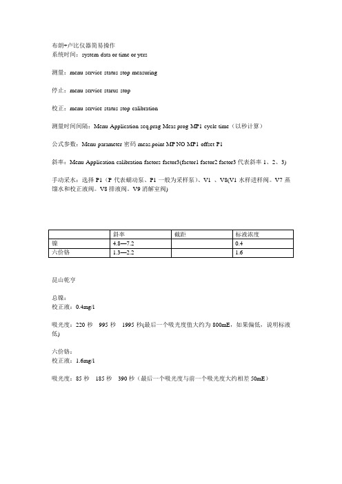
镍
4.8—7.2
0.4
六价铬
1.3—2.2
1.6
昆山乾亨
总镍:
校正液:0.4mg/l
吸光度:220秒995秒1995秒(最后一个吸光度值大约为800mE,如果偏低,说明标液低)
六价铬:
校正液:1.6mg/l
吸光度:85秒185秒390秒(最后一个吸光度与前一个吸光度大约相差50mE)
布朗+卢比仪器简易操作
系统时间:system-data or time or yers
测量:menu-service-status-stop-measuring
停止:menu-service-starus-stop
校正:menu-service-status-stop-calibration
测量时间间隔:Menu-Application-seq.prag-Meas prog-MP1-cycle time(以秒计算)
公式参数:Menu-parameter-密码-meas.point-MP NO-MP1-offset-P1
斜率:Menu-Application-calibration-factors-factor3(factor1 factor2 factor3代表斜率1、2、3)
手动采水:选择P1(P代表蠕动泵、P1一般为采样泵)、V1、V8(V1水样进样阀。V7蒸馏水和校正液阀。V8排液阀。V9消解室阀)
哈Expr 3556A Psophometer 操作和维修手册说明书

ErrataTitle & Document Type: 3556A Psophometer Operating and Service Manual Manual Part Number: 03556-90000Revision Date: August 1973About this ManualWe’ve added this manual to the Agilent website in an effort to help you support your product. This manual provides the best information we could find. It may be incompleteor contain dated information, and the scan quality may not be ideal. If we find a bettercopy in the future, we will add it to the Agilent website.HP References in this ManualThis manual may contain references to HP or Hewlett-Packard. Please note that Hewlett- Packard's former test and measurement, life sciences, and chemical analysisbusinesses are now part of Agilent Technologies. The HP XXXX referred to in this document is now the Agilent XXXX. For example, model number HP8648A is now model number Agilent 8648A. We have made no changes to this manual copy.Support for Your ProductAgilent no longer sells or supports this product. You will find any other availableproduct information on the Agilent Test & Measurement website:Search for the model number of this product, and the resulting product page will guideyou to any available information. Our service centers may be able to perform calibrationif no repair parts are needed, but no other support from Agilent is available.。
联想硬盘保护
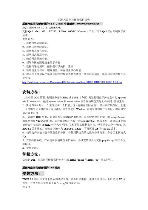
联想网络同传硬盘保护说明联想网络同传硬盘保护6.5.0 ,bom中显示为:000000000000003287KQY_EDU6.5.0_SC_T12(PREAPP)支持Q45,G41,G31,RS780,RS690,945GC(Cancun)平台,对于Q45平台限制同以前版本。
变更要点:1、新增网络升级功能。
2、新增排程克隆功能。
3、新增断点续传功能。
4、新增日志显示功能。
5、修改网络测速功能。
6、新增分区克隆进度条显示功能。
7、数据传输完成后,接收端可以关机、重启。
8、新增增量同传中,删除增量,保存增量核心功能。
9、将系统下硬盘保护驱动和网络控制软件整合成统一的软件安装包:驱动与网络控制工具安装包。
/CommercialPC/Introduction/Kaiqi/HDD_PROTECT/EDU_6.5.0.iso安装方法:1、启动至DOS界面,若硬盘中存在HPA或TYPE12分区,则运行硬盘保护光盘中的hpatool /clr和hdtool /clr,直到hpatool /view和hdtool /view中看到的硬盘实际大小相同,然后重启;2、使用Gdisk划分一个主分区和一个扩展分区(将磁盘空间占满),然后在扩展分区上创建一个逻辑分区(将扩展分区占满);或直接使用Windows安装光盘创建二个分区,将磁盘空间占满也可以;3、启动至DOS界面,如果是预装DOS/XP的机型,运行硬盘保护光盘中的setup12x.bat;如果是预装VISTA的机型,运行硬盘保护光盘中的setup12v.bat;然后重启;注意这2个批处理文件安装的TYPE12分区大小不同,互相不能实现整盘同传,但功能是完全一样的。
从EDU6.2版本开始,安装命令统一为SETUPT12.BA T,不再区分XP和VISTA版本。
4、使用选择安装功能将硬盘重新分区,若使用快速安装功能则必须将第二个分区重新格式化;5、安装操作系统,在系统中安装硬盘保护驱动,并设置转移页面文件pagefile.sys等文件至数据区;6、安装完成。
HPATOOL使用说明

升级说明:HPATOOL 只用于给HPA 中各模块划分空间,在硬盘指定位置的表中建立各模块的位置和大小,以供安装和各模块查询使用.硬盘指定位置支持<<联想硬盘保护区管理规范(V0.6)>>和<<LEOS HPA Partion Spec v2 2004-05-20>>2种方式: 使用说明:1. HPATOOL 在线查看使用说明: 使用HPATOOL_/? ( ‘_’表示空格)即可看见帮助信息.LENOVO ® HPA Tool Version 0.80ACopyright(C) Lenovo Group Ltd. 1984-2005 All Rights Reserved HPA TOOL [/COMMAND] [/HDDx]HPA TOOL [/TYPEID xxxx(m)/(g)] [/HDDx] /? --For Help/TYPEID xx(m)/(g) –Build HMPT & (LEOS) PART TABLE According to TYPEID. /INIT --Build HMPT & (LEOS) PART TABLE According to Setup.TXT. /CLR --Clear HMPT & (LEOS) PART TABLE == Release HPA for User. /VIEW --Display All Records in HMPT & (LEOS) PART TABLE. /XF(/SY) --Build Flag for XF(XiaoFei) or SY(ShangYong). /HDDx (default HDD0) (x=0-7) select which HDD you want to install .if 1 HDD (include SA TA) linked , you can Only type /HDD0 or use DEFAULT if 2 HDDs (include SA TA) linked , you can Only type /HDD0 or /HDD1 The number x is decided by the sequence below:IDE Channel 0 Master ,Channel 0 slave ,Channel 1 Master, …,2.HPATOOL查看硬盘中HPA及各模块状态: 使用HPATOOL_/VIEW( ‘_’表示空格)如下:LENOVO INFORMA TION HPA Tool Version 0.80ACopyrightINFORMATION Lenovo Group Ltd. All Rights ReservedHDD Actual Size : 38166 Mbytes ==== 04A8B570 SectorsHPA Size : 0 Mbytes ==== No HPA Indeed48 Bit Feature : Not Support !************************* HPA Module Partition Table *************************Name: TypeID: Position: Size: :In MegaBytes=============================From Max===========In Hex=========Deciaml========R4 Kernal: 0201 0000A330 0000A130 20System: 1003 0040C3A3 00401E73 2051: 0006 00412812 0000626F 12: 0007 004925E0 0007FBCE 255硬盘状态包括:a.硬盘Native Max大小;b.硬盘实际可用大小;c.受保护的HPA大小;d.是否支持48bit 访问方式;各模块状态显示包括: 模块对应名称,TYPEID,安装状态,位置,大小(16进制,10进制),3.HPATOOL用命令行方式进行模块划分:例如使用:hpatool_/typeid_size_/typeid_size_/typeid_size_/typeid_size( ‘_’表示空格)hpatool_/0201_20m_/1003_2G_/0006_10M_0007_250m( ‘_’表示空格)再使用HPATOOL /VIEW查看如下:LENOVO INFORMATION HPA Tool Alpha 0.50BCopyrightINFORMATION Lenovo Group Ltd. All Rights Reserved************************* HDD Infomation Table *************************HDD Native Max : 38166 Mbytes ==== 04A8B56F SectorsHDD Actual Size : 38166 Mbytes ==== 04A8B570 SectorsHPA Size : 0 Mbytes ==== No HPA Indeed48 Bit Feature : Not Support !************************* HPA Module Partition Table *************************Name: TypeID: Position: Size: :In MegaBytes=============================From Max===========In Hex=========Deciaml========R4 Kernal: 0201 No 0000A330 0000A130 20System: 1003 No 0040C3A3 00401E73 2051: 0006 No 00412812 0000626F 12: 0007 No 004925E0 0007FBCE 2554. HPATOOL用命令行方式进行删除时,只支持全部清除例如:hpatool_/clr ( ‘_’表示空格)即将所有模块记录都清除;注意:hpatool /clr清除只清除了模块分配表HMPT,而没有清除已安装的各模块的实际内容。
pH-M400简要操作说明(0706)

M400-pH简要操作说明1. 功能说明和接线1.1. 功能说明M300-pH用于测量pH值,其操作模式包括三个部分:测量、校准和参数设置。
在设置模式中按“Menu”键可回到测量模式。
1.1.1. 测量模式用于正常运行时仪器进行pH的测量。
1.1.2. 校准模式(Cal)用于pH电极。
在显示屏的上方显示(校准)图标。
1.1.3. 设置模式(Conf)用于调整仪器的运行参数(参见3)。
进入的的步骤为:在测量模式下按enter键,用 和 键输入密码1200,按“Enter”键进入设置模式。
1.2. 端子说明TB1:继电器输出TB2:模拟量输出/数字输入TB3:传感器输入接口1.3. 电缆接线:端子号VP电缆AS/AK电缆1(pH电极)透明线(玻璃电极)同心电缆内芯(玻璃电极)3(参比电极)红线(或屏蔽线)通信电缆屏蔽线4 黄绿线/蓝6(Pt100/1000)白线8(Pt100/1000)绿线注:在电极在无溶液接地时要将端子3和4跨接(短路)在电极温度传感器有线电阻补偿时需将灰线接到变送器接口TB3的第7端子。
2. 校准模式2.1. 进入校准模式:进入校准模式的步骤为:在测量模式下按“Cal”键,用 和 键选择所需的校正模式(1point(一点校正);2point(两点校正);process(过程校正)),按“Enter”键确定(我们一般都选择2point)。
校准步骤:在校准模式下,将干净2.2. 查看校准参数:在测量模式下按“Cal”键,不输入密码,直接按“Enter”键,可查看最近一次的校准参数,包括零点和斜率。
3. 参数设置Menu3.1.1. Quick setup3.1.1.1测量参数的设定:选择a或b设定测量的单位pH和温度的单位3.1.1.2模拟输出:设置Aout1的上下限值Aout1min和Aout1max分别是4mA和20mA 所对应的测量值3.1.2参数设定(路径Meun/Configure/Measurement)3.1.2.1Channel setup (通道设定)3.1.2.2pH(缓冲液选择):(路径Meun/Configure/Measurement/pH)将mettle-9 改为NIST STd3.1.2.3Set Averaging(设置滤波)3.1.3设置模拟输出(路径:Menu/Configure/Analog Outputs)3.1.3.1输出类型(Aout Type)Normal (线形) Bi-linear(双线性) logarithmic(对数)一般我们选择较多的是Auto range(自动量程)要多一些,他既可以是4-20mA也可以是0-20mA;若选择Auto range则可以设置Aout1的上下限值Aout1min和Aout1max。
伯莱姆率增强型气压仪说明书

First things firstFor use in hazardous locations •MGP7000X meriGauge® plus•MS700X meriSense™DisclaimerPlace only meriSense sensorsinside the meriGauge plushousing.Steps to get startedMake pressure connectionThe meriSense has a 316 stainless steel 1/4 in. male NPT connection for direct mounting. •The threads should be coated with a pipe sealant compound before installation. •Tighten to finger tight plus 1.5 turns to3 turns using a 23 mm (7/8 in.) wrench.Remember: The gauge will face the samedirection as the Meriam logo on the sensor.Never rotate meriSense byturning meriGauge plus.Use only a wrench on the hex fitting. Know your batteriesThe meriGauge plus is powered by four 1.5volt AA size batteries.•Use only batteries listed on 9R525.•Never mix batteries—not bymanufacturer, by size, by capacity, or bychemistry.•Never mix old and new batteries.•Remove all four batteries in themeriGauge plus at the same time.•Replace all four batteries with batteriesfrom the same package or with thesame expiration date.Install the batteriesDo not change batteries inexplosive atmospheres.1.Turn over the meriGauge plus so the displayfaces down.2.Remove the four screws on the battery coverwith the Phillips head screwdriver by turningthem counterclockwise.3.Remove the plastic battery compartmentcap.4.Pay attention to the positive (+) andnegative (−) battery polarity markings at thebottom of the compartment as you installthe batteries.5.Install the plastic battery compartment cap.6.Replace the metal battery cover. To securethe cover, torque the screws clockwise 0.56N-m (5 in-lbs) maximum.Connect meriGauge plus tomeriSenseThe notch on the sensor must face the samedirection as the meriGauge plus for the sensor tolock in place. Simply slide the gauge housing onthe sensor until it fully connects.Learn the function keysUSB cable & meriSuite™ CGFor use onlyin non-hazardous locationsConnect the USB cable to meriGauge plus andto your computer to configure meriGauge plusand meriSense using the meriSuite CG app.Install meriSuite CG & USBDriversYou must install USB Drivers first then install themeriSuite CG app. For installation instructions:https:///resources/download/Open meriSuite CGUse meriSuite CG application to:•Sync PC Time to Gauge for data loggingand display.•Select or deselect the Display Modes oneach gauge or Measurement Units that youneed on each sensor.•Select the timeout for the Backlight and forthe Auto Off.Watch meriSuite CG & batteriesDo not turn off the power onthe meriGauge plus while it iscommunicating with meriSuiteCG.Close meriSuite CG first, disconnect the USB,and turn off the meriGauge plus.The meriGauge plus System Quick Start GuideHow often is a new pressure measurement displayed?The meriGauge plus display updates with a new pressure measurement five times per second.What are the different Display modes on the gauge?The meriGauge plus has nine display modes:1. Normal 5. Tare (T.OFF, T.ON)2. Minimum (MIN) 6. Average (AVG)3. Maximum (MAX) 7. Rate of change (RATE)4. Accuracy (+/–) 8. Data Log Lite(DATA LOG)9. Time & Temperature Why are the available units different between a 15 psi and3 000 psi meriSense?If a given measurement unit cannot display the correct number of digits, the meriGauge plus automatically advances to the next displayable unit.What does it mean when the red backlight flashes?•The flashing red backlight indicates an error condition.•Possible error conditions are:o Pressure has exceeded the statedaccuracy of the meriSense.o Pressure has fallen below the stated accuracy of the meriSense.•The red backlight overrides the white backlight. FAQsWhat does the Zero (Ø) key do?In normal measure modeIf the sensor is within a tolerance band aroundzero, press and hold the Zero key to zero thepressure measurement and to reset the Minand Max measurements.Note: The tolerance band is approximately± 1 % of the Full Scale pressure value of thesensor.In Min or Max modePress and hold the Zero key to reset the Minand Max measurement. However, this does notzero the pressure measurement.In Tare modeWhen the Tare is off (T.OFF), press and hold theZero key to turn on Tare (T.ON) and to set theTare value at the current pressuremeasurement.Likewise, when the Tare is on (T.ON), press andhold the Zero key to turn off the Tare mode.In Average modePress and hold the Zero key to restart the rollingaverage.Holding the Zero keyThe key must be held to perform the Zero orTare mode. The displayed value(s) dashes outduring the zero or tare process.Which version of Data Log is on mygauge?1.Make sure the sensor is installed.2.Turn on the gauge.3.Press the Display button until “DATA LOG”appears.4.Press the Information button. Theversion appears: Vers. Pro or Vers. Lite.FAQsHow long does the white backlightstay on after the Backlight key ispressed?The white backlight has an automatic timeout. Ifno keys have been pressed, the backlightautomatically turns off after 1 minute.Note: You can configure the backlight timeoutwith meriSuite CG.What does the bar graph at the topof the display indicate?•The bar graph displays a live indication ofthe current pressure applied to the sensoras a % of Full Scale.•However, when the battery percentage isdisplayed, the bar graph follows the largedigit display in indicating the remainingstate of charge for the batteries.Is it OK to leave the sensorattached to a pipe without a gaugeconnected?•Yes.•Make sure to replace the dust cap on thesensor to protect the electrical contactsafter the sensor has been detached from ameriGauge plus gauge.What does a low battery indicatormean?Be prepared to change batteries when you seethe outline of the battery icon or when theoutline of the icon flashes.FAQsHow long will the gauge remain onif I leave it unattended?•The default setting is Always On.•You can configure the timeout for Auto Offwith meriSuite CG.How to contact usContact SalesIf you have any issues, questions, orsuggestions, please contact us using one of thefollowing methods.****************Meriam®10920 Madison AveCleveland | Ohio | 44102 | USA+ 1 216 281 1100(800) 817-7849。
HPA使用详解
HPA技术细节前言一、什么是HPA二、目前采用HPA技术的恢复系统简介三、DIY版一键恢复系统设计思路四、附加资源前言为什么采用HPA技术呢?用Ghost、 Acronis True Image不是很好吗?你也许会问,是的,这也是首先我必须为大家解释的问题。
传统一键恢复系统介绍:所谓的一键恢复,实际上原理都是类似的:修改硬盘的主引导记录(MBR),用自己的一段引导代码来代替默认的引导代码,这段引导代码的作用就是在启动时给用户一个提示“按某某键开始恢复系统”,在用户按下这个键后,激活硬盘上的一个隐藏的主分区(Primary Partition),然后从这个分区启动某个恢复软件来用事先备份好的系统恢复用户损坏的系统。
早期的一键恢复最大的特点就是那个隐藏分区在分区软件(包括Windows的磁盘管理器)中是可见的,你随时可以删除它,这也是不安全因素之一。
当然,这用来应付普通用户的情况已经足够了。
缺点:1、隐藏分区可被破坏、删除,造成无法成功恢复系统。
2、隐藏分区必须为一个主分区,会对用户造成一些不便。
基于HPA技术的一键恢复系统的优势:1、HPA技术可以提供用户级安全性保护,以全面保护HPA分区不被未授权用户访问、修改及删除。
根据白皮书上提供的安全性对应表来看,在最高等级的安全性下,无法访问、看到、删除HPA分区,无法克隆,而最低的安全性设置下,可以在操作系统中看到该分区,可删除、可克隆、可更新数据。
2、不必占用一个主分区。
一、什么是HPAHidden protected area或Host protected areaHPA是在ATA/ATAPI-4里面定义的一个区域,在BIOS可见空间之后,所以通过BIOS访问不到。
但是可以通过直接发送AT命令的方式访问。
通俗的理解就是设置读取的硬盘最大的扇区号,从而把高端的内容隐藏起来,这个最大的扇区号能够写在硬盘的某个地方,因此即使你把这个硬盘挂到其它机器上,正常情况下你也看不到隐藏的内容,Fdisk、PowerQuest PartitionMagic 之类的工具也把这个硬盘当做一个稍小容量的硬盘。
在线PH说明书精讲

在线PH测量仪使用说明书型号:PH-2005A无锡沃曼尼科技有限公司前言非常感谢您选择本公司PH分析仪器!在使用本产品前,请详细阅读本说明书,并保存以供参考。
请遵守本说明书操作规程及注意事项。
⏹由于不遵守本使用及安装说明书中规定的注意事项,所引起的任何故障和损失均不在厂家的保修范围内,厂家亦不承担任何相关责任。
请妥善保管好所有文件。
如有疑问,请联系我公司售后服务部门或地区客服中心。
⏹如果您需要英文说明书,请登陆本公司网站下载,或拨打服务热线,联系我公司售后服务部门或地区客服中心。
⏹在收到仪器时,请小心打开包装,检查仪器及配件是否因运送而损坏,如有发现损坏,请联系我公司售后服务部门或地区客服中心,并保留包装物,以便寄回处理。
⏹当仪器发生故障,请勿自行修理,请联系我公司售后服务部门或地区客服中心。
用户须知●使用时请遵守本说明书之操作规程及注意事项。
●在使用过程中若发现仪器工作异常或损坏请联系经销商,切勿自行修理。
●为使测量更精确,仪器须经常配合电极进行标定;若您的电极购买时间已近一年或电极存在质量问题,请注意更换。
●执行标定工作之前请将仪器通电预热三十分钟。
●因产品更新换代,本说明书如有变动恕不另行通知。
注意:因PH电极线为特殊专用线,请勿剪接。
若因剪接造成仪表无法标定等其他问题,厂家概不负责。
目录1.概述…………………………………………2.技术性能……………………………………3.主要功能配制………………………………4.温度补偿(选配)……………………………5.信号输出……………………………………6.安装步骤……………………………………7.安装示意图…………………………………8.后面板接线图………………………………9.前面板说明…………………………………10.仪器操作…………………………………11.PH电极使用保养…………………………12.PH标准缓冲液PH值对照表………………概述我公司生产的PH-2005A是一种用于测试和控制PH值的精密仪表。
效率源专业版说明书

效率源迈拓固件修复说明书简版注:本次为效率源推出的迈拓固件修复程序第一版(美钻II),过完农历春节后,效率源科技会及时推出迈拓一系列的程序。
下一个将要推出的为4D系列.. 3.2R.. 2F… 6E.. 6Y.. 至到所有的迈拓系列推出完整。
目前这个版本只能修美钻II代即2B0X0h1 系列,切记不要用于修复其他系列的迈拓硬盘,因为每个系列的硬盘内部的表结构是不一样的,可能将好盘修坏或越修越坏。
本迈拓美钻版新增了很多新的功能,希望各位客户能首先熟悉美钻II的修复方式,以便在推出以后的迈拓其他系列时能尽快入手。
首先来说明一下窗口的含义:(1)校准窗口,这是直接调用硬盘内部的自修复程序时,使用自校准功能后,可以通过这个窗口看到硬盘目前的状态。
(2)驱动器状态,这个窗口可以看到目前的硬盘状态,如果硬盘正常的话,即可接受你操作的指令,如果提示驱动器出错,那什么指令都能使用。
(3)修复模块显示窗,可以看到硬盘的那些模块是正确的。
有错误的程序可以直接修复。
当然可以分两次检测,第一次修复后,重新启动本程序,再检测一次,看上次出错的位置是否已经被修复。
如果反复不能进行修复的话,建议使用自动校准功能。
(4)功能键选择:(由上向下介绍)关闭电源:可以使用软件来开关硬盘电源,需要电源控制模块,目前暂不能使用*转换列表:将G-list转成P-list,这个功能最大的好处是在使完硬盘坏道后使用一次,迈拓美钻II代最多允许加入635个G-list坏道,超过的话就会出现问题,即大家常遇到的认ANTHEN或电机转一下即停的问题(当然不是所有的问题都是G-list溢出造成的,迈拓通病有5成是这种原因),所以建议只要修过的迈拓硬盘均转换一次,而留足G-list,供以后客户在使用硬盘时遇到坏道,硬盘可以自己加入。
打开电机(关闭电机):本功能是为热换电路板修复固件而设立,在美钻II上可能使用率不高,但在美III、金8、金9 等新型号的硬盘中使用较多。
- 1、下载文档前请自行甄别文档内容的完整性,平台不提供额外的编辑、内容补充、找答案等附加服务。
- 2、"仅部分预览"的文档,不可在线预览部分如存在完整性等问题,可反馈申请退款(可完整预览的文档不适用该条件!)。
- 3、如文档侵犯您的权益,请联系客服反馈,我们会尽快为您处理(人工客服工作时间:9:00-18:30)。
升级说明:HPATOOL 只用于给HPA 中各模块划分空间,在硬盘指定位置的表中建立各模块的位置和大小,以供安装和各模块查询使用.硬盘指定位置支持<<联想硬盘保护区管理规范(V0.6)>>和<<LEOS HPA Partion Spec v2 2004-05-20>>HPATOOL 具体划分空间支持2种方式: 使用说明:1. HPATOOL 在线查看使用说明: 使用HPATOOL_/? ( ‘_’表示空格)即可看见帮助信息.LENOVO (R) HPA Tool Alpha 0.50BCopyright(C) Lenovo Group Ltd. All Rights Reserved HPATOOL [/COMMAND] [/HDDx]HPATOOL [/TYPEID xxx(m)/(g)] [/HDDx] /? --For Help/TYPEID xx(m)/(g) –Build HMPT & (LEOS) PART TABLE According to TYPEID./CLRHDD --Clear HMPT & (LEOS) PART TABLE == Release HPA for User. /INIT --Build HMPT & (LEOS) PART TABLE According to Setup.TXT. /VIEW --Display All Records in HMPT & (LEOS) PART TABLE. /HDDx (default HDD0) (x=0-7) select which HDD you want to install .if 1 HDD (include SA TA) linked , you can Only type /HDD0 or use DEFAULT if 2 HDDs (include SA TA) linked , you can Only type /HDD0 or /HDD1 The number x is decided by the sequence below:IDE Channel 0 Master ,Channel 0 slave ,Channel 1 Master, …,201HPATOOL查看硬盘中HPA及各模块状态: 使用HPATOOL_/VIEW( ‘_’表示空格)如下:LENOVO INFORMA TION HPA Tool Alpha 0.50BCopyrightINFORMATION Lenovo Group Ltd. All Rights ReservedHDD Actual Size : 38166 Mbytes ==== 04A8B570 SectorsHPA Size : 0 Mbytes ==== No HPA Indeed48 Bit Feature : Not Support !************************* HPA Module Partition Table *************************Name: TypeID: Position: Size: :In MegaBytes=============================From Max===========In Hex=========Deciaml========R4 Kernal: 0201 0000A330 0000A130 20System: 1003 0040C3A3 00401E73 2051: 0006 00412812 0000626F 12: 0007 004925E0 0007FBCE 255硬盘状态包括:a.硬盘Native Max大小;b.硬盘实际可用大小;c.受保护的HPA大小;d.是否支持48bit 访问方式;各模块状态显示包括: 模块对应名称,TYPEID,安装状态,位置,大小(16进制,10进制),201HPATOOL用命令行方式进行模块划分:例如使用:hpatool_/typeid_size_/typeid_size_/typeid_size_/typeid_size( ‘_’表示空格)hpatool_/0201_20m_/1003_2G_/0006_10M_0007_250m( ‘_’表示空格)再使用HPATOOL /VIEW查看如下:LENOVO INFORMATION HPA Tool Alpha 0.50BCopyrightINFORMATION Lenovo Group Ltd. All Rights Reserved************************* HDD Infomation Table *************************HDD Native Max : 38166 Mbytes ==== 04A8B56F SectorsHDD Actual Size : 38166 Mbytes ==== 04A8B570 SectorsHPA Size : 0 Mbytes ==== No HPA Indeed48 Bit Feature : Not Support !************************* HPA Module Partition Table *************************Name: TypeID: Position: Size: :In MegaBytes=============================From Max===========In Hex=========Deciaml========R4 Kernal: 0201 No 0000A330 0000A130 20System: 1003 No 0040C3A3 00401E73 2051: 0006 No 00412812 0000626F 12: 0007 No 004925E0 0007FBCE 2554. HPATOOL用命令行方式进行删除时,只支持全部清除例如:hpatool_/clr ( ‘_’表示空格)即将所有模块记录都清除;TOOL使用说明:201划分模块空间是从指定的SETUP.TXT中以’/’开始的记录进行划分.其中每条模块记录以’/’开始的格式指定以’;’结尾;所有模块最后结束标志是/END.这样省去了每次输入各模块TYPEID 和大小等参数;0201 20m;/1003 2G;/0006 10m;/0007 250m;/END; == For HPATOOL.EXE Example ==========================================; ‘/TypeID 300m;’;; ^ ^ ^ ^ ^; 1 2 3 4 5; 1.Must be ‘/’;; 2.Must be 4 bits;; 3.Must be 1 blank;; 4.Unit can use ‘m/M’ or ‘g/G’;; 5.Must be ‘;’;; ===================================================================== 配置文件式划分空间时,请使用hpatool_/init; ( ‘_’表示空格)配置文件式清除空间时,请使用hpatool_/clr; ( ‘_’表示空格)升级说明:[MSETUP 使用说明]:MSETUP 用于依照HPA 分配表中各TYPEID 记录,安装各模块相应文件或删除各模块;具体安装和删除支持2种方式: :使用MSETUP_/? ( ‘_’表示空格)即可看见帮助信息.Copyright(C) Lenovo Group Ltd. All Rights ReservedMSETUP [/COMMAND] [/HDDx]MSETUP [/TYPEID Filename] [/HDDx] MSETUP [/DEL TYPEID] [/HDDx] /? --For Help/TYPEID Filename --Install X Module According to TYPEID /DEL TYPEID --Uninstall X Module According to TYPEID /INST --InstallX Module According to Setup.txt /CLR --Uninstall X Module According to Setup.txt/HDDx (default HDD0) (x=0-7) select which HDD you want to install .if 1 HDD (include SATA) linked , you can Only type /HDD0 or use DEFAULT if 2 HDDs (include SATA) linked , you can Only type /HDD0 or /HDD1 The number x is decided by the sequence below:IDE Channel 0 Master ,Channel 0 slave ,Channel 1 Master, ...,1. MSETUP支持多模块同时安装;例如使用:MSETUP_/TYPEID_MODULEFILE_/TYPEID_MODULEFILE_/MAIN DM.ROM ( ‘_’表示空格)MSETUP_/0201_33.DAT_/1003_D:\R4\R4.DA T_/0006_55.DAT_/0007_66.DAT( ‘_’表示空格) LENOVO (R) HPA Module Setup Alpha 0.50BCopyright(C) Lenovo Group Ltd. All Rights ReservedSuccess to Get Info From SETUP.txt !Start To Install: 33.DATTo TypeID:0201%Success to Get Info From SETUP.txt !Start To Install: D:\R4\R4.DATTo TypeID:1003%Success to Get Info From SETUP.txt !Start To Install: 55.DATTo TypeID:0006%Success to Get Info From SETUP.txt !Start To Install: 66.DATTo TypeID:0007%使用HPATOOL /VIEW 可以发现相应各TYPEID旁显示YES,表示已安装;LENOVO (R) HPA Tool Alpha 0.50BCopyright(C) Lenovo Group Ltd. All Rights Reserved************************* HPA Module Partition Table *************************Name: TypeID: Position: Size: :In MegaBytes=============================From Max===========In Hex=========Deciaml========R4 Kernal: 0201 Yes0000A330 0000A130 20System: 1003 Yes0040C3A3 00401E73 2051: 0006 Yes00412812 0000626F 12: 0007 Yes004925E0 0007FBCE 255使用MSETUP安装时,如果模块已安装,会直接覆盖安装.注意:/MAIN 参数一定要放在所有参数的最后。