看门狗安装、操作、维护说明书V2_2(印刷版A5)新
WonderWare硬狗安装方法
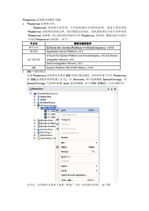
Wonderware加密狗安装操作步骤:1.Wonderware加密狗分类:Wonderware加密狗分很多种,不同的机器用不同的加密狗,现场主要用到的Wonderware加密狗有四到五种,现在根据实际情况,按机器的角色安装不同种类的Wonderware加密狗(接口服务器有两种型号的Wonderware加密狗,根据功能不同使用不同的Wonderware加密狗),如下:2.IDE中属性修改:安装Wonderware加密狗首先要在IDE环境中修改属性,在四屏环境下打开Wonderware 的IDE(必须要在四屏机器上打开),在Derivation项中选择模板IntouchViewApp,在IntouchViewApp下选择终端IT_mode选用的模板,如下图$IT_ETBZZ,点击右键打开:打开后,在界面中从菜单下选择“特别”下的“应用程序类型”,如下图:打开界面后,勾选InTouchView应用程序,如下图:点击“确定”按钮后,会出现保存页面,保存的时候页面一定要最大化全屏,否则,保存时的页面时多大的,平台运行时的界面就是多大。
修改完模板$IT_ETBZZ的属性后,它下面的所有的IT_mode对象的属性都会被修改,修改后所有的对象都需要重新部署一下。
3.更换License“IDE中对象属性修改完毕后,就可以导入新的License了。
第一步:如图打开License Utility界面第二步:下图为License Utility界面,用鼠标选择画面中右上角画红圈的1,使用打勾的那个按钮做删除删除操作,即删除原来的临时的License文件。
第三步:把加密狗里随带的小光盘放入光驱,鼠标单击菜单,File=>Install License File,弹出选择框,如下图选择光盘下的WWSUITE.LIC,单击打开:第四步:弹出如下,查看机器名称是否一致,单击ok,在所选的机器上安装新的License文件。
看门狗计时器 程序说明书

看门狗计时器程序说明
本说明只针对采用Winbond W83627HF(super I/O)系列芯片的产品。
要使用看门狗功能需先将主板上的WATCHDOG跳线跳成RESET模式
一 Winbond W83627HF可提供的功能如下:
1程序控制看门狗功能的启动与停止
2计时器计数范围从1-255,时间单位为秒或者分。
3本公司产品只提供复位功能。
计时结束后,系统将重启。
二看门狗计时器编程说明:
1程序执行流程:
2看门狗计时器寄存器说明
INDEX(2EH) DATA(2FH)
87H ――写两次,启动super I/O
07H 08H 选择寄存器
F5H 选择时间单位
秒
00H
分
08H
F6H 计数范围
停止计数
00H
01H-FFH 1-255任意
AAH ――停止看门狗功能
三例子:DOS下运行DEBUG命令
-O 2E 87
-O 2E 87 ;启动
-O 2E 07
-O 2F 08 ;选择寄存器
-O 2E F5
-O 2F 00 ;计时单位为秒
-O 2E F6
-O 2F 10 ;计时时间10秒
回车后,系统将在10秒后重启。
注:由于Winbond W83627HF芯片的问题,在使用分钟为计时单位时将会快半分钟。
F2X16 V2 系列 IP MODEM 使用说明书

F2X16V2系列IP MODEM 使用说明书此说明书适用于下列型号产品:客户热线:400-8838-199电话:+86-592-6300320传真:+86-592-5912735网址:地址:厦门集美软件园三期A06栋11层F2X16V2系列IP MODEM使用说明书文档版本密级V1.0.0产品名称:F2X16V2共32页型号产品类别F2116V2GPRS IP MODEM F2A16V2LTE IP MODEM文档修订记录日期版本说明作者2020-02-24V1.0.0初建ZDM2/31著作权声明本文档所载的所有材料或内容受版权法的保护,所有版权由厦门四信通信科技有限公司拥有,但注明引用其他方的内容除外。
未经四信公司书面许可,任何人不得将本文档上的任何内容以任何方式进行复制、经销、翻印、连接、传送等任何商业目的的使用,但对于非商业目的的、个人使用的下载或打印(条件是不得修改,且须保留该材料中的版权说明或其他所有权的说明)除外。
商标声明Four-Faith、四信、、、均系厦门四信通信科技有限公司注册商标,未经事先书面许可,任何人不得以任何方式使用四信名称及四信的商标、标记。
3/31/314注:不同型号配件和接口可能存在差异,具体以实物为准。
目录第一章产品简介 (6)1.1产品概述 (6)1.3工作原理框图 (7)1.4产品规格 (8)第二章安装 (10)2.1概述 (10)2.2开箱 (10)2.3安装与电缆连接 (10)2.4电源说明 (13)2.5指示灯说明 (13)第三章参数配置 (14)3.1配置连接 (14)3.2参数配置方式介绍 (14)3.3参数配置详细说明 (14)3.3.1配置工具运行界面 (15)3.3.2设备上电 (16)3.3.4中心服务 (22)3.3.5串口 (23)3.3.6无线拔号 (24)3.3.7全局参数 (26)3.3.8设备管理 (27)3.3.9其它功能项 (28)第四章数据传输试验环境测试 (29)4.1试验环境网络结构 (29)4.2测试步骤 (29)5/316/31第一章产品简介1.1产品概述F2X16V2系列IP MODEM 是一种物联网无线数据终端,利用公用蜂窝网络为用户提供无线长距离数据传输功能。
QuickGuard 快速安装指南说明书

INSTALLATION GUIDE QuickGuard® STANDARD & EXPRESSTABLE OF CONTENT1. FOREWORD (1)2. SPECIAL NOTES (1)3. SAFETY PRECAUTIONS (1)4. FENCING DESCRIPTION (1)5. GENERAL INSTRUCTIONS (1)6. MODIFY FENCE (3)7. FENCE ASSEMBLING (5)Assemble framework (5)Fixation of infill material (13)Assembly of conventional door. (21)Assembly of sliding door. (23)8. QUICK GUARD-EXPRESS ASSEMBLY (25)9. CLEANING AND MAINTENANCE (27)10. TECHNICAL DATA (27)All given dimensions are in mm unless otherwise statedWe reserve the right to make technical changes or modify the contents of this document prior notice. With regard to purchase orders, the agreed particulars shall prevail. Troax AB does not accept any responsibility whatsoever for potential errors or possible lack of information in this document.We reserve all rights in this document and in the subject matter and illustrations contained therein. Any reproduction, disclosure to third parties or utilization of its contents – whole or in parts – is forbidden without prior written consent of Troax AB.1.FOREWORDThis installation guide describes how to assemble QuickGuard Standard fence in general.For installation of QuickGuard Express –see “QuickGuard Express Installation guide”2.SPECIAL NOTESPay attention to the following special notes in this guideImportant!A tip!3.SAFETY PRECAUTIONSAlways use adequate personal safety equipment during installation, e.g. safety googles and ear protection.Always use safety googles and ear protection when cutting aluminum profiles with a hacksaw or mitre saw, and use protection gloves when handling meshes, glass or other material that can have sharp edges.If the fence isn’t bolted to the ground, secure it temporary to p revent it from tipping over.4.FENCING DESCRIPTIONThere are two versions of QuickGuard fencing system available, QuickGuard Standard and QuickGuard Express. Both versions are aluminum systems and can be combined with each other if needed.The main difference between QuickGuard Standard and QuickGuard Express, is that Standard have a 44x44 profile between the posts and Express have a U-profile in between.QuickGuard Standard has more possibilities in terms of infill materials and adaptations.5.GENERAL INSTRUCTIONSFixation of the fence to the ground is normally done at the very end. Do not fix the fence to the floor unless vertical profiles (posts) are aligned vertically and parallel to each other.If possible, start the installation were the fence can stand free, e.g. a corner or were it can be supported temporary to a fixed part.L-brackets are used in corners, end posts, door blade etc.T-brackets are used when connecting e.g. two horizontal profiles with a post.There is no drilling or tapping needed to connect the aluminum profiles, just press the pre-assembled bracket against the profiles and loosen the screw(s) about one turn anti-clockwise. Then tighten the screw clockwise until it’s fixed.IMPORTANT!Make sure that hammer nut has turned (90°) into correct position in the aluminum profile.Lower and middle horizontal profile shall be connected to each post with one bracket, normally mounted on the side facing outwards from the machine.Upper horizontal profile shall be connected to each post with two brackets, one on the inside and one on the outside.6.MODIFY FENCEQuickGuard can easily be adapted and modified on site. Aluminum profiles, polycarbonate sheets, steel mesh e.t.c. can easily be cut without using any tools that generate heat (=no fire risk).•Avoid tools that can generate heat and cause a fire, e.g. angle grinder.•Make sure that material to be cut is adequately supported and clamped during the cutting operation.•Use adequate personal safety equipment.Cut meshWhen cutting the welded mesh the wire ends should be at least 15 mm or cut flush to the joining wire.DIMENSION TABLE FOR INFILL MATERIALSExampleA polycarbonate sheet shall be cut to fit an opening where A=1500 and B=800. According to the dimension table the sheet should be 1520 (1500+20) x 820 (800+20).7.FENCE ASSEMBLINGAssemble frameworkSTEP 1.Pre-mount floor brackets on to the post profile according to example pictures below. Make sure that bottom part of the floor bracket aligns with the profile end before tightening the fixation screws. Also, make sure that hammer nuts are positioned correctly inside the profile.Note!At least two (2) floor brackets shall be used on each postMark where the fence will be installed. Use a chalk line to get a straight line as a reference.STEP 3.Mount lower horizontal profile on to a post. Make sure that distance between floor and lower part of the horizontal profile is correct, and that hammer nuts are positioned correctly inside the profile.Note!Post must be mounted so that floor brackets are perpendicular to the fence.TIP!Use a spacer block to facilitate installation and mount the horizontal profile in correct position.Mount next post on to the horizontal profile. Use a spacer block to place the profile in correct position.Polycarbonate sheetTear off a small area of the protective film from both sides of the polycarbonate sheet (fig1), and insert infill material in lower part. Bend the sheet (fig.2) and/or press the post apart to insert the sheet in to the profile T-slot.Tip!Leave the protective film on as long as possible to prevent damages on the surface.MeshBend the mesh and/or press the post apart to insert the mesh in to the profile T-slot. Make sure that the mesh is oriented with the vertical wires facing closest to the outside.Steel panelBend the steel panel and/or press the post apart to insert the mesh in to the profile T-slot. The convex side of the steel panel should be facing outwards.If steel panel shall be secured with infill securing strip (JSM PL1_) and cellular rubber (JSM G2), cellular rubber have to be mounted on to the steel panel before inserting the steel panel in to the frame work. Cellular have to beLaminated glass 6,4mmMount rubberstrip (JSM G3) all around the glass.Fig.1 Fig.2 Fig.3Place the middle horizontal profile between the posts and press it down against the polycarbonate sheet. Lift the middle horizontal profile ~3mm and fix it with L-brackets. Make sure that distance between the two horizontal profiles are correct. It shall be possible to move the infill material ~3mm vertically and horizontally when profile is fixed.Mount the rest of the fence…3. 4.5. 6.7. 8.11. 12.13.Position the fence on the floor and make sure that door posts are aligned vertically and parallel to each other before fixing the fence to the floor. Use adequate fixation bolts and center the drill in the fitting holes (fig.1)Note!Make sure that posts are in line with each other and that door posts are parallel before fixing the fence to the floor.Fixation of infill materialSelection of fixation componentJSM PL1_ / -PL2_Infill securing stripJSM PL3 Panel lockJSM NL3 Net lockJSM G2 Cellular rubber 5x20mmProduct W JSM PL1_ 6,5 JSM PL2_7,5Polycarbonate sheetTear and fold up about 100mm of the protective film all around the sheet, on both sides before securing the sheet in the frame work.3mm thicknessUse infill securing strip (JSM PL1_) together with cellular rubber (JSM G2) or panel lock (JSM PL3) to secure the sheet in the frame.4mm thickness.Use infill securing strip (JSM PL2_) or panel lock (JSM PL3) to secure the sheet in the frame.5mm thicknessUse infill securing strip (JSM PL1_) or panel lock (JSM PL3) to secure the sheet in the frame.Fixation with panel lock JSM PL3Panel lock JSM PL3 is normally mounted from the outside of the fence, on all four sides. Mount panel lock evenly distributed every 300-400mm starting maximum 250mm from corner (fig 1). Tighten the torx (T25) screw so it penetrates the polycarbonate surface about 2mm, max torque 3Nm.Use a cordless drill machine with torque control when mounting panel lock.Fig 1Fixation with infill securing strip JSM PL1_ or JSM PL2_Infill securing strip JSM PL1_/-PL2_ is normally mounted from the outside of the fence, on all four sides. JSM PL1_/-PL2_ is available in a few pre-cut lengths as listed in table 1 below. Any other length has to be cut on site. Length should be about 2mm shorter than the distance between the connecting profiles.Table 1Laminated glassThe glass is mounted with a u-rubber strip (JSM G3) in the profile groove. Rubber strip should be mounted all around the glass, before the glass are inserted in to the frame work.• Use protection gloves. • Carry the glass upright• It’s recommended to be two persons handling the glass.Fig.1Mounting the rubber stripL= (L1+L2) x 2 + 50 Step 2Make a 90° V-cut out from the rubber stripStep 3Mount the rubber strip on to the edge of the glass. Step 4Fold the rubber strip and press it on to next edge.Step 5Make a new V-cut and press it on to the next edge.Step 6Mounting laminated glass and sound absorbing panel1.Premount vertical profiles with floor brackets by first loosening the screw anti-clockwise. Then tighten the screw clockwise in the usual way. A spacer between the floor and the lower horizontal profile will make the installation easier.3.Insert the sound absorbing panel (1) in to the frame and put the horizontal profile above (2). The perforated side of the panel should normally be facing towards the sound source.5.Insert the glass (1) in to the frame and put the upper horizontal profile above (3). 2.Assemble mounting profile JSM AS1 all around the panel. The profile should be fixed on to the panel. If it’s to loose, increase the slot a little by pressing the “walls” together.4.Assemble the U-rubberstrip (JSM G3) all around the glass.6.Insert next sound absorbing panel at the same way as described previously, see step 2 and 3 above.7.Insert next glass same way as described previously, see step 4 and 5 above.8.Fix the profiles with L- and T-brackets, two brackets on the upper part (inside and outside) if possible, and one bracket on the other parts, normally on the outside.9.Adjust the fence and fix it to the floor with accurate fixations.Normally two (2) floor brackets are used per post and then fixed with one (1) bolt per floor bracket. If only one (1) floor bracket is used per post, both (2) fixation holes must be used.Assembly of conventional door.1) Install and fix fence to ground. Mount L- and T-brackets (JSM 32B-K & JSM 33B-K) on both sidesof the fence on the top. Make sure the door posts are paralell to each other before fixing them to the ground.2) Premount the door. Mount L-brackets (JSM 32B-K) on both sides on corners.3) Open the hinges for access to the screws. Put the door on the ground in the opening and mount the hinges onto the fence. Make sure that nuts turn out correctly and lift the dorr to correct hight and then tighten the screws,4) Mount door stops (JSM D13A) and eventual safety switches.Assembly of sliding door.1) Install and fix fence to ground. Mount L- and T-brackets (JSM 32B-K & JSM 33B-K) on both sides of the fence on the top. Make sure the door posts are paralell to each other before fixing them to the ground.2Premount the sliding door. Slide in the suspension wheels (JSM D5) into the 44x44 profile before putting on the endcaps (JSM L1B). Mount L-brackets (JSM 32B-K) on both sides on corners.3) Mount guiding components (JSM D12 & JSM D12A) onto the fence.4) Take the premounted door blade and slide it in to the guiding rail and guiding components.5) Mount door stops (JSM D13 & JSM D13B) and eventual safety switches.8.QUICK GUARD-EXPRESS ASSEMBLY9.CLEANING AND MAINTENANCECleaningAluminium profiles (anodized)•Use a mild neutral detergent (pH 6-8) and/or waterPolycarbonate sheets•Use a mild soap solution and a soft cloth.•Do not use abrasive or highly alkaline cleaners.•Never scrape the sheet with squeegees, razor blades or other sharp instruments.•Do not clean sheet in hot sun or at elevated temperatures as this can lead to staining.10.TECHNICAL DATA。
看门狗介绍

看门狗(watchdog)"看门狗"(watchdog) ,又叫 watchdog timer,是一个定时器电路,是在由单片机构成的微型计算机系统中,为了防止单片机的工作受到来自外界电磁场的干扰,造成程序的跑飞,陷入死循环,而设计的用于监测单片机程序运行状态的芯片。
若程序程序的跑飞,陷入死循环,正常运行将会被打断,由单片机控制的系统将无法继续工作,会造成整个系统的陷入停滞状态,发生不可预料的后果。
◆基本原理在系统运行以后也就启动了看门狗的计数器,看门狗就开始自动计数,如果到了一定的时间还不去清看门狗,那么看门狗计数器就会溢出从而引起看门狗中断,造成系统复位。
看门狗可使单片机可以在无人状态下实现连续工作,其工作原理是:看门狗芯片和单片机的一个I/O引脚相连,该I/O引脚通过程序控制它定时地往看门狗的这个引脚上送入高电平(或低电平),这一程序语句是分散地放在单片机其他控制语句中间的,一旦单片机由于干扰造成程序跑飞后而陷入某一程序段进入死循环状态时,写看门狗引脚的程序便不能被执行,这个时候,看门狗电路就会由于得不到单片机送来的信号,便在它和单片机复位引脚相连的引脚上送出一个复位信号,使单片机发生复位,即程序从程序存储器的起始位置开始执行,这样便实现了单片机的自动复位。
◆分类和使用方法看门狗可分为硬件看门狗和软件看门狗两种。
硬件看门狗:硬件看门狗的主体是一个定时电路,并由被监控CPU提供周期性“喂狗”信号,对定时器清零(俗称“清狗”)。
CPU正常工作时,由于能定时“清狗”,看门狗内的定时器不会溢出。
当CPU出现故障,则不能继续提供“清狗”信号,使得看门狗内定时器不断累加而溢出,从而触发一个复位信号对CPU进行复位,使CPU重新工作。
常用的看门狗芯片有ADM706/MAX706,为了使硬件看门狗更可靠,使用起来更灵活,当今主流的设计方式都是看门狗芯片配合逻辑器件(CPLD)来使用。
此时,看门狗有三种清狗方式:1)正常工作时,CPU输出WDI信号清狗;2)CPU关闭看门狗(不输出WDI信号),由CPLD输出WDI清狗信号,此方法不推荐使用,容易出问题,有的设计规范中是严禁CPU关闭看门狗的;3)CPU挂死后,CPLD主动输出WDI清狗信号一段时间,如果CPU仍未恢复正常,则不再继续清狗,等待看门狗芯片内部定时器溢出后输出复位信号对CPU进行复位。
eye xo2 安装指南说明书

NoticeGrounding InstructionsIn the event of a malfunction or breakdown, grounding provides a path of least resistance for electrical current to reduce the risk of electric shock. This tool is equipped with an electrical cord having an equipment grounding conductor and a grounding plug. The plug must be plugged into a matching outlet that is properly installed and grounded in accordance with all local codes and ordinances.Step 1: Hardware Installation GuideStep 2: Software Installation GuideContentsSectionPageWARNING: To Ensure Safe Use4 - 51. Installation Environment62. Included Items73. Hardware Install8 3.1 Mounting Bracket 9 3.2 Slide Sensor 10 3.3 Connection3.4 Connection Status 11 125. Software Install13 - 206. Club Sticker Guide21 - 2728To Ensure Safe UseImproper handling or operation of this machine may result in injury or damage to property. Points which must be observed to prevent injury or damage are described as follows.WARNING Used for instructions intended to alert the user to therisk of severe injury should the unit be usedimproperly.Used for instructions intended to alert the user to the Cautionrisk of injury or material damage should the unit beused improperly. Material damage refers to damageto home, furnishing, or anything within the unit’svicinity.NEVER This symbol alerts the user to items that should neverbe carried out.To Ensure Safe Use - ContinuedInstall in a level and stable location. Failure to do so may result in falling of the machine, leading to injury.Never attempt to disassemble, repair, or modifyshock, or injury. Entrust repairs to a trained technician.Never use outside or in any location where exposure to water or high humidity may occur. Do not touch the power cord or electrical outlet with wet or dirty hands.Doing so may result in electrical shock.Conduct play in a clean and brightly lit location. Operating in a dark or cluttered space may lead toaccidents.Be aware of your surroundings and use cautiously with children around. Swinging the club during playwithout being aware will result in serious injury or death.WARNINGThis is a heavy machine.Installation EnvironmentPC Specifications:Category RequirementCPU Intel i5 8400 or higher*RAM8 GBGraphics Card GeForceGTX 1060 or higherOperating System Windows 10 (64bit) Version 1803 or higher Resolution1920 x 1080Connectivity Ethernet Port Required* AMD: 3rd gen Ryzen or higher and AMD Ryzen 3600 or higher (AMD 2700 is not compatible).Installation Environment 9’-Included ItemsThe following items are included with the sensor. Make sure they are all present and accounted for.EYEXO2 Sensor BarBracketEmail – Software InstallerCalibration ChartPower CablePower Adapter Power Connector USB Ethernet AdapterEthernet LAN CableLevelClub StickersM4 32mm screwsM6 15mm screws M6 15mm high screws M6 15mm low screwsIncluded ItemsHardware InstallWARNINGSection 1 “Installation Requirements,” and outlinebracket location on ceiling.Consult with building manager or landlord aboutbefore installation. The sensor and bracket are approximately 30 lbs and 9 M4 32mm screws are required to screw in the bracket and hold the sensor. Failure to do so may result in serious injury or damage toproperty.CAUTIONTwo or more persons are recommended for mounting the bracket on the ceiling and extreme caution is required while on the ladder. Failure may result in serious injury ordamage to property.LadderPhillips Screwdriver M4 32mmScrew x9 BracketSensor BarNecessary ToolNecessary Part(s)HardwareWARNINGStep 1: Mount BracketThe EYE XO2 Sensor and bracket come attached together in the box. Slightly loosen the black M6 15 mm screws that are holding the sensor to the bracket so you can remove it. Please make sure you have measured 3.5 feet from the front and middle of the sensor to your tee position. Do NOT align to the bracket.Place the ladder under the location on the ceiling where the bracket will be mounted. Place the bracket flat against the ceiling with the hinges facing down toward the ground. The longer side of the hinges must be closet towards theimpact screen.With the bracket in position, grab the 10 silver M4 32mm screws and screw them in the locations below in the diagram.M9 32mm (5)M9 32mm (5)132HardwareStep 2: Slide SensorAfter the bracket has been firmly mounted to the ceiling, you will install the sensorbar.The sensor bar comes with 6 black M6 15mm screws already inserted; 3 screws in the front and 3 screws in the back. Make sure all 6 screws are about halfway into the bar and even in length.Slide the sensor bar with the 6 screws up and over through the bracket hinges. Make sure the screws are secured in the hook part of the hinges. Once the sensor is secured in the bracket hinges, tighten the 6 screws to the bracket.The tilt of the sensor can be adjusted with the high and low M6 15mm screws. The regular M6 15mm screws are already screwed into the sensor. You can change this outwith the M6 155 High or Low screws to adjust the angle/ tilt.M6 15mmM6 Low 15mmM6 High 15mm Hardware3123.3Hardware Install - Continued Step 3: ConnectionEthernet LANCable Power Cord Power AdapterPowerConnectorNecessary PartsTake out the Ethernet LANcable from the box. Connectthe end with the tag that reads“Connect this side of LAN cableto Sensor ONLY” to the sensor.Connect the other endDIRECTLY to your PC ethernetport and NOT the USB adapter.Take out all 3 components ofthe power source: powercable, power adapter, andpower connector. Connect all3 accordingly and connect the“Power Connector” enddirectly to the sensor asshown below. Turn on redswitch.Note: The plug must be plugged into a matching outlet that is properly installed andgrounded in accordance with all local codes and ordinances.An extra green grounding wire is provided on the end of the power connector in caseyour outlet is not grounded.Hardware 12EYE XO2 INSTALLATION GUIDE113.4Hardware Install – ContinuedStep 4: Connection StatusMake sure to check the connection status before you start thesoftware installation process.Check and see if the power is on. You will see a bright red light on the switch of the sensor.Check and see if your EYE XO2 Sensor and PC are paired through the network.Hardware12Please refer to our “Network Setup Guide” below to set the IPaddress.NETWORK GUIDEEYE XO2 INSTALLATION GUIDE12Software Install WARNINGPlease make sure PC requirements are met from section1 “Installation Environment,” before the installationprocess. Failure to do will result in installation issues and slow gameplay .WARNINGPlease make sure the connection statuses are clear and everything is paired. Failure to do will result in installation issues.SoftwareSoftware Install – Continued EYE XO2 InstallationYou will receive an email with a license codefrom your retailer which looks like this:Please download it and save it to the UneekorFolderClick here: EYE XO2 Installer LinkCtrl + Click the EYE XO2 Installer link above to begin EYE XO2 Installation or manually enter the URL: https:///dist/EYEXO2/Uneekor_EYEXO2_Setup.exeUnder downloads you will see,“Uneekor_EYEXO2_Setup.exe” Clickopen file.“Uneekor EYE XO2 (2.10.0.0)Setup” will open. Click “Next.” Software23 41EYEXO2_30000XXXXX.license.3.5 Software Install – ContinuedEYE XO2 Software InstallationKeep the destination folder as“C:\Uneekor” and click Install.Please wait while installercompletes installation.5 6Software3.6 Software Install – ContinuedEYE XO2 Software Installation**If these two pop-ups occur, please hit ok for both.The “Run Uneekor EYE XO2” is checked. Uncheck it and click finish .7Software3.7 S oftware Install - ContinuedEYE XO2 Sensor ActivationGo to the C: Drive-> Uneekor Folder -> Device -> Launch Monitor -> EYEXOFind and double click “EYEXO2_Check”In the “EYEXO” folder click on “EYEXO2_Activation”Click “Browse” to find the license key saved from step 1 above.Then click “Activation” After adding the license please click “Activate.”The EYE XO2 Sensor installation is now complete.2If you don’t get the Sensor LAN connection, please refer to our “Network Settings Guide.”Make sure the Sensor LAN connection is good before the software installation process.1EYEXO2_40000XXXXX.licenseSoftware3.8 Software Install - ContinuedEYE XO2 Network Config1Once the sensor has been activated,you will have a screen like the oneon the right. Click Set NetworkParam & Firewall to continue2After the selection, you will be askedto restart the PC. Click Yes to restartto finish the Sensor installation3.8 Software installation - ContinuedEYE XO2 CalibrationTo complete the installation of the EYE XO2.Follow the calibration guide linked below:EYE XO2 Calibration Guide3.9Software Install – ContinuedVIEW Software InstallationClick here: VIEW Installer Ctrl + click on the VIEW Installer above or enter the URL manually: https:///dist/View/VIEW_Setup.exeOpen downloads on the right.If you receive this warning, follow the steps below.3.8.1Hover over the download,click the 3 dots on the rightside, and click keep.3.8.2Click the “Show more” dropdown and click “Keep anyway.”3.8.3Then click “Open file” underdownloads.“VIEW_SETUP 20220721 Setup” will open. Click “Next.”Software125.6 Software Install – ContinuedVIEW Software InstallationKeep the Destination Folder as “C:\VIEW” and click “Install.”Check the “I agree” box and click “Install.”If a error pops up, click close and continue to VIEW Setup.Click “Start setup”34SoftwareIf the C++ files are already installedon your PC, you may receivethe error on the rightClick Close and then nextto continueOptional :5.7 Software Install – ContinuedVIEW Software InstallationMake sure all boxes are checked and the Directory matches the picture on the right, then Click “Next.”Click “Finish”Click “browse” and select the license file you saved in the Uneekor folder from the earlier steps, and click “Activation. Then click “Activate” VIEW Software installation isnow complete.567SoftwareThe speed of the club before impact.The amount of energy transferred from the club head to the golf ball.The angle difference between Face Angle and Club Path.angle is measured relative to the horizon.The in to out or out to in movement of the club head’s geometric center atthe time of impact. Club Path is the directon (right or left) the club head ismoving at impact and is measured relative to the target line.The direction (right or left) the club face is pointed at impact. It ismeasured relative to the target line.GUIDE22The amount of loft of the club face at the center point of impact.Where you strike the ball on the club face.FPOFPO2-2.4 inches13Driver 48 groove1. Bar StickerAlign the middle of the Bar Sticker to the horizontal center line or the 7th groove.2. Dot StickerAlign to the middle of the bar sticker andparallel between the grooves.15 61Center Groove*In the case where you do have to raise the horizontal line beyond the center to fit all 4 corners of the Bar Sticker, the data will be calculated higher.262277.1 SpecificationsEYE XO2 INSTALLATION GUIDE 28Items Contents Components 3 High Speed Cameras 4Infrared LED Boards1 Control Board1 Power BoardData Interface Ethernet (CAT6 and above) Communication Speed 1 GbpsSpin Data Total Spin ±12,000 rpmMeasurement Range Ball Speed Putter: 0.1 m/s ~ 30 m/s Ball Speed Driver/Iron: 5 m/s ~ 100 m/sSensing Angle Driver: -5 ~ 50 DegreeIron: 0.1 ~ 80 Degree (shots over 60° can damage the unit)***************** *******************。
智能设计MSS看门狗配置文档说明书

SmartDesign MSS Watchdog ConfigurationDoc Version 1.02 Watchdog ConfigurationTable of ContentsIntroduction...................................................................................................................3 Configuration Options..................................................................................................3 Port Description (3)Watchdog Configuration3IntroductionThe SmartFusion Microcontroller Subsystem (MSS) provides a Watchdog timer peripheral that guards against system crashes by requiring that it is regularly serviced by the ARM Cortex-M3 or by a processor in the FPGA Fabric.The actual behavior of the SmartFusion MSS WATCHDOG core must be defined at the application level using the SmartFusion MSS Watchdog Driver provided by Actel.This document describes the ports that are available on the Watchdog core in the SmartDesign MSS Configurator. For more details about the MSS Watchdog hard peripheral, please refer to the Actel SmartFusion Microcontroller Subsystem User's Guide .Configuration OptionsThere are no configuration options for the Watchdog core in the SmartDesign MSS Configurator.Figure 1: WATCHDOG Instance in SmartDesign for SmartFusionPort DescriptionPort NameDirection PAD?DescriptionWDINT OutNo This is asserted ( if enabled ) when a counter timeout occurs and interrupt rather than resetgeneration has been selected.Note:Non-PAD ports must be promoted manually to the top level from the MSS configurator canvas to be available as the next level of hierarchy.Actel Corporation2061 Stierlin Court Mountain View, CA 94043-4655 USA Phone 650.318.4200 Fax 650.318.4600Actel Europe Ltd.River Court, Meadows Business Park Station Approach, Blackwater Camberley Surrey GU17 9AB United KingdomPhone +44 (0) 1276 609 300 Fax +44 (0) 1276 607 540Actel JapanEXOS Ebisu Building 4F 1-24-14 Ebisu Shibuya-ku Tokyo 150, JapanPhone +81.03.3445.7671 Fax +81.03.3445.7668 Actel is the leader in low-power and mixed-signal FPGAs and offers the most comprehensive portfolio of system and power management solutions. Power Matters. Learn more at .© 2009 Actel Corporation. All rights reserved. Actel and the Actel logo are trademarks of Actel Corporation. All other brand or product names are the property of their respective owners.Actel Hong KongRoom 2107, China Resources Building 26 Harbour Road Wanchai, Hong Kong Phone +852 2185 6460 Fax +852 2185 6488 5-02-00247-0。
加密狗本地写狗操作说明

加密狗本地写狗操作说明
加密狗本地写狗操作说明
一、适用的加密狗类型:Windows版DVR、MVR软件加密狗(如图)
二、操作步骤
1、在Windows系统的主机插上加密狗
2、加密狗在系统下显示正常状态后打开写狗软件RockeyServer.exe(如图)
3、在红框的位置填写要写入加密狗的通道数,并点击“写入”按钮,写入成功后会在
右上部分蓝框的位置有“写入成功”的提示。也可以点击“读取”按钮验证写入是否成功。
三、写狗软件由分公司执行经理控制,不得泄漏给客户或者其它人员。
看门狗 驱动程序
看门狗是当CPU进入错误状态后,无法恢复的情况下,使计算机重新启动有两种办法来处理这种情况:一是:采用人工复位的方法二是:依赖于某种硬件来执行这个复位工作。
这种硬件通常叫做看门狗(Watch Dog,WD)看门狗实际上是一个定时器,其硬件内部维护了一个定时器,每当时钟信号到来时,计数寄存器减1。
如果减到0,则系统重启. 如果在减到0之前,系统又设置计数寄存器一个较大的值,那么系统永远不会重启。
系统的这种设置能力表示系统一直处于一种正常运行状态。
反之,如果计算机系统崩溃,那么就无法重新设置计数寄存器的值。
当计数寄存器为0,系统重启看门狗的工作原理很简单,处理器内部一般都集成了一个看门狗硬件。
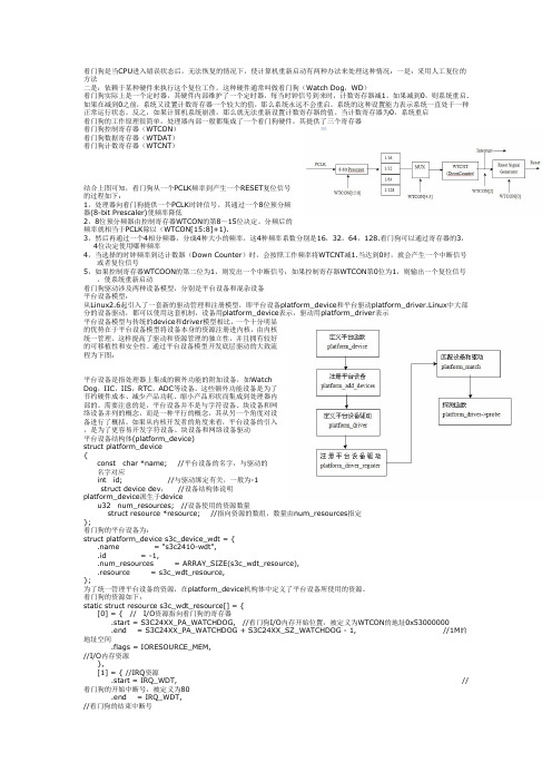
其提供了三个寄存器看门狗控制寄存器(WTCON)看门狗数据寄存器(WTDAT)看门狗计数寄存器(WTCNT)结合上图可知,看门狗从一个PCLK频率到产生一个RESET复位信号的过程如下:1,处理器向看门狗提供一个PCLK时钟信号。
其通过一个8位预分频器(8-bit Prescaler)使频率降低2,8位预分频器由控制寄存器WTCON的第8~15位决定。
分频后的频率就相当于PCLK除以(WTCON[15:8]+1).3,然后再通过一个4相分频器,分成4种大小的频率。
这4种频率系数分别是16,32,64,128.看门狗可以通过寄存器的3,4位决定使用哪种频率4,当选择的时钟频率到达计数器(Down Counter)时,会按照工作频率将WTCNT减1.当达到0时,就会产生一个中断信号或者复位信号5,如果控制寄存器WTCOON的第二位为1,则发出一个中断信号;如果控制寄存器WTCON第0位为1,则输出一个复位信号,使系统重新启动看门狗驱动涉及两种设备模型,分别是平台设备和混杂设备平台设备模型:从Linux2.6起引入了一套新的驱动管理和注册模型,即平台设备platform_device和平台驱动platform_driver.Linux中大部分的设备驱动,都可以使用这套机制,设备用platform_device表示,驱动用platform_driver表示平台设备模型与传统的device和driver模型相比,一个十分明显的优势在于平台设备模型将设备本身的资源注册进内核,由内核统一管理。
SCS-900操作维护手册V2.1

加密狗安装使用说明79【精品推荐-doc】
加密狗安装使用说明79【精品推荐-doc】加密狗安装使用说明
一、下载并安装加密狗驱动程序
请注意:在安装驱动前不要插加密狗。
1、先到以下地址下载加密狗驱动:
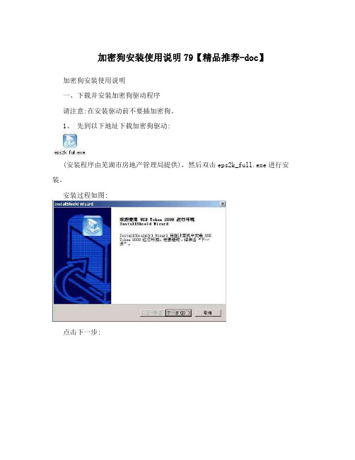
(安装程序由芜湖市房地产管理局提供),然后双击eps2k_full.exe进行安装。
安装过程如图:
点击下一步:
确认安全警告:点击“仍然继续”
到此,加密狗驱动程序安装完成。
二、安装加密狗
请注意:一定要在驱动安装成功后再插上加密狗。
安装成功后重新启动计算机,并将加密狗插在计算机USB接口上。
此时弹出“找到新硬件向导”,选择“否,暂时不(T)”,并点击“下一步”
选择“自动安装软件(推荐)”,并点击“下一步”
在硬件安装的对话框中点击“仍然继续”,进入下一步安装
点击完成,结束安装
二、使用加密狗访问“芜湖市网上房地产系统”
第一步:打开浏览器在地址栏里输入网址:后按回车键,弹出确认“安全警报”的对话框,请点击“是”,继续操作。
(注意,此处浏览器需要验证加密狗的信息,可能需要几十秒时间,请耐心等待)
接着弹出“选择数字证书”的对话框,选择下方的数字(即加密狗的编号),点击确定进入下一步。
接着弹出“客户PIN码验证”,输入加密狗的PIN码:1234,点击“确定”,进入“芜湖市网上房地
产系统”登陆界面。
(注意,密码输入错误三次,加密狗将永久失效,所以输入密码时务必小心)。
看门狗MAX705、706、813中文说明
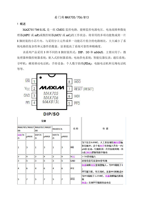
看门狗MAX705/706/8131 概述MAX705/706/813L是一组CMOS监控电路,能够监控电源电压、电池故障和微处理器(MPU或mP)或微控制器(MCU或mC)的工作状态。
将常用的多项功能集成到一片8脚封装的小芯片内,与采用分立元件或单一功能芯片组合的电路相比,大大减小了系统电路的复杂性和元器件的数量,显著提高了系统可靠性和精确度。
该系列产品采用3种不同的8脚封装形式:DIP、SO和mMAX。
主要应用于:微处理器和微控制器系统;嵌入式控制器系统;电池供电系统;智能仪器仪表;通信系统;寻呼机;蜂窝移动电话机;手持设备;个人数字助理(PDA);电脑电话机和无绳电话机等等。
2 功能说明2.1 RESET/RESET操作复位信号用于启动或者重新启动MPU/MCU,令其进入或者返回到预知的循环程序并顺序执行。
一旦MPU/MCU处于未知状态,比如程序“跑飞”或进入死循环,就需要将系统复位。
对于MAX705和MAX706而言,在上电期间只要Vcc大于1.0V,就能保证输出电压不高于0.4V的低电平。
在Vcc上升期间RESET维持低电平直到电源电压升至复位门限(4.65V或4.40V)以上。
在超过此门限后,内部定时器大约再维持200ms后释放RESET,使其返回高电平。
无论何时只要电源电压降低到复位门限以下(即电源跌落),RESET引脚就会变低。
如果在已经开始的复位脉冲期间出现电源跌落,复位脉冲至少再维持140ms。
在掉电期间,一旦电源电压Vcc降到复位门限以下,只要Vcc不比1.0V还低,就能使RESET维持电压不高于0.4V的低电平。
MAX705和MAX706提供的复位信号为低电平RESET,而MAX813L提供的复位信号为高电平RESET,三者其它功能完全相同。
有些单片机,如INTEL的80C51系列,需要高电平有效的复位信号。
2.2 看门狗定时器MAX705/706/813L片内看门狗定时器用于监控MPU/MCU的活动。
独立看门狗一般步骤

独立看门狗一般步骤独立看门狗,是一种能够监测电脑系统状态并作出相应反应的软件。
其主要功能是检测计算机是否出现异常行为,例如病毒破坏、恶意软件、未授权访问和其他攻击行为。
下面是独立看门狗常见的步骤:一、选择一个独立看门狗软件在市场上有很多种独立看门狗软件可供选择,例如Windows系统默认的Defender、Malwarebytes等。
选择一个高效可靠的独立看门狗软件非常重要,能够减少用户面临计算机安全威胁的机会。
二、安装独立看门狗软件在选择好独立看门狗软件后,需要先安装该软件并进行基础设置,例如开启实时监测、自动更新等功能。
同时也需要对其进行设置,以让其满足用户的需要。
三、启动独立看门狗软件在进行基础设置后,需要将独立看门狗软件启动。
启动独立看门狗软件后,它将会开始实时监测计算机的状态,包括文件、程序、系统等的变化。
四、独立看门狗警报处理如果独立看门狗软件检测到异常行为,例如病毒入侵、恶意软件等,会自动触发警报。
用户需要迅速进行处理,如快速隔离病毒、阻止恶意软件攻击、限制未授权访问等。
五、进行独立看门狗软件更新为了保证独立看门狗软件的高效性和实用性,需定期进行独立看门狗软件的更新。
更新能够及时修复独立看门狗软件发现的安全漏洞、增强安全防护能力等。
六、独立看门狗运行与系统资源消耗在使用独立看门狗的过程中,需要注意其运行与系统资源消耗问题。
独立看门狗运行需要占用一定的系统资源,如CPU、内存等。
过度占用会降低计算机的运行效率,可能会导致系统崩溃等问题。
以上便是独立看门狗常见的步骤,用户可以根据自己的需求和实际情况来采取相应的措施。
独立看门狗可以为用户提供全面的实时保护,多年来一直是网络安全领域的重要产品。
看门狗驱动详解
【WinCE驱动】基于S3C2440A芯片的看门狗驱动【引子】小弟日前正在开发一个仪器项目,核心芯片采用三星公司的S3C2440A,操作系统移植的是微软公司的WinCE5.0。
在实际调试中发现,系统由于受到强干扰而经常死机,虽然后来在硬件上增加了屏蔽等措施,效果已经很好,但这个问题仍引起了我的重视,因此我打算采用看门狗来增强系统最终的可靠性。
然而,现有的开发包(BSP)并没有看门狗驱动,只能自己动手写了。
经过两个白昼的努力,终于搞定,现将这个看门狗驱动整理出来,以免以后忘记了,毕竟“好记性不如烂笔头”。
【步骤】WinCE下的驱动,一般分为本机驱动(Native Driver)和流驱动(Stream Driver)两种。
对于我们的应用,大多数都可以归结到流驱动,而我的看门狗驱动正是按照流驱动格式来编写的。
基本思路就是利用S3C2440A的定时器1来产生中断,然后在中断程序中完成“喂狗”这一动作,从而实现看门狗功能。
首先,在Drivers目录下建立一个子目录watchdog,然后建立4个文件:makefile、source、wdg.DEF、wdg.c。
【makefile】文件内容如下(就一句):!INCLUDE $(_MAKEENVROOT)\makefile.def【source】文件内容如下:RELEASETYPE=PLATFORMTARGETNAME=wdgTARGETTYPE=DYNLINKTARGETLIBS=$(_COMMONSDKROOT)\lib\$(_CPUINDPATH)\coredll.libDLLENTRY=DllEntryDEFFILE=wdg.defSOURCES = \wdg.c \【wdg.DEF】文件内容如下:LIBRARY wdgEXPORTSwdg_Initwdg_Deinitwdg_Openwdg_Closewdg_Readwdg_Writewdg_Seekwdg_IOControlwdg_PowerUpwdg_PowerDown【wdg.c】文件内容如下:#include <windows.h>#include <types.h>#include <tchar.h>#include <excpt.h>#include <cardserv.h>#include <cardapi.h>#include <tuple.h>#include <devload.h>#include <diskio.h>#include <nkintr.h>#include <windev.h>#include "BSP.h"#define PUBLICHANDLE g_hInstance;HANDLE IntThread;HANDLE IntEvent;UINT32 g_TimerIrq = IRQ_TIMER1;UINT32 g_SysIrq = SYSINTR_UNDEFINED;DWORD dwTime;DWORD wtdata;DWORD num;volatile S3C2440A_W ATCHDOG_REG *v_pWDGregs; // 创建watchdog寄存器指针对象volatile S3C2440A_PWM_REG * v_pPWMregs;volatile S3C2440A_INTR_REG * v_pINTregs;BOOL wdg_InitAddr(void);void Vitural_Alloc(void);void Timer_Init(void);DWORD Timer_IST(void);void Vitural_Alloc(void){/* INTR Register Allocation */v_pINTregs = (volatile S3C2440A_INTR_REG *)VirtualAlloc(0, sizeof(S3C2440A_INTR_REG), MEM_RESERVE, PAGE_NOACCESS);if (v_pINTregs == NULL){ERRORMSG(1,(TEXT("For INTRregs : VirtualAlloc failed!\r\n")));}else{if (!VirtualCopy((PVOID)v_pINTregs, (PVOID)(S3C2440A_BASE_REG_PA_INTR >> 8), sizeof(S3C2440A_INTR_REG), PAGE_PHYSICAL | PAGE_READWRITE | PAGE_NOCACHE)){ERRORMSG(1,(TEXT("For INTRregs: VirtualCopy failed!\r\n")));}}/* PWM Register Allocation */v_pPWMregs = (volatile S3C2440A_PWM_REG *)VirtualAlloc(0, sizeof(S3C2440A_PWM_REG), MEM_RESERVE, PAGE_NOACCESS);if (v_pPWMregs == NULL){ERRORMSG(1,(TEXT("For PWMregs : VirtualAlloc failed!\r\n")));}else{if (!VirtualCopy((PVOID)v_pPWMregs, (PVOID)(S3C2440A_BASE_REG_PA_PWM >> 8), sizeof(S3C2440A_PWM_REG), PAGE_PHYSICAL | PAGE_READWRITE | PAGE_NOCACHE)){ERRORMSG(1,(TEXT("For PWMregs: VirtualCopy failed!\r\n")));}}}void Timer_Init(void){v_pPWMregs->TCFG0 &= ~0xFF;v_pPWMregs->TCFG0 |= 199; // Timer1 预分频值199v_pPWMregs->TCFG1 &= ~(0x0F<<4);v_pPWMregs->TCFG1 |= (0<<20)|(3<<4); // Timer1 分频值16v_pPWMregs->TCON &= ~(0xF << 8);v_pPWMregs->TCNTB1 = dwTime;v_pPWMregs->TCON |= (2 << 8);v_pPWMregs->TCON |= (9 << 8); //自动装载模式,启动Timerv_pPWMregs->TCON &= ~(1 << 9); //这句很重要,这句不写定时器将不会启动v_pINTregs->INTMSK &= ~(1<<IRQ_TIMER1); //使能Timer中断}DWORD Timer_IST(void){DWORD dwStatus;IntEvent = CreateEvent(NULL, FALSE, FALSE, NULL);if (!IntEvent){RETAILMSG(1, (TEXT("ERROR: Timer: Failed to create event.\r\n")));return FALSE;}if (!InterruptInitialize(g_SysIrq, IntEvent, NULL, 0)){RETAILMSG(1,(TEXT("Fail to initialize Timer interrupt event\r\n")));return FALSE;}while(1){dwStatus=WaitForSingleObject(IntEvent, INFINITE);if(dwStatus == WAIT_OBJECT_0){v_pWDGregs->WTCNT=wtdata;//0x6000;//更新看门狗计数器num++; //测试InterruptDone(g_SysIrq);// RETAILMSG(1,(TEXT("Complete Timer Interrupt.num=%d.\r\n"),num));}else{CloseHandle(IntEvent); //这句很重要}}}BOOLwdg_InitAddr(void){BOOL RetValue = TRUE;v_pWDGregs = (volatile S3C2440A_WATCHDOG_REG *)VirtualAlloc(0, sizeof(S3C2440A_W ATCHDOG_REG), MEM_RESERVE, PAGE_NOACCESS);if (v_pWDGregs == NULL){ERRORMSG(1,(TEXT("For wdg_regs : VirtualAlloc failed!\r\n")));RetValue = FALSE;}else{if (!VirtualCopy((PVOID)v_pWDGregs, (PVOID)(S3C2440A_BASE_REG_PA_W ATCHDOG>> 8), sizeof(S3C2440A_W ATCHDOG_REG), PAGE_PHYSICAL | PAGE_READWRITE | PAGE_NOCACHE)){ERRORMSG(1,(TEXT("For wdg_regs: VirtualCopy failed!\r\n")));RetValue = FALSE;}}if (!RetValue){RETAILMSG (1, (TEXT("::: wdg_InitializeAddresses - Fail!!\r\n") ));if (v_pWDGregs){VirtualFree((PVOID) v_pWDGregs, 0, MEM_RELEASE);}v_pWDGregs = NULL;}else{// RETAILMSG (1, (TEXT("wdg_InitializeAddresses - Success\r\n") ));}return(RetValue);}BOOL WINAPIDllEntry(HANDLE hInstDLL,DWORD dwReason,LPVOID lpvReserved){switch(dwReason){case DLL_PROCESS_ATTACH://g_hInstance = hInstDLL;RETAILMSG(1,(TEXT("wdg: DLL_PROCESS_ATTACH.\r\n")));DisableThreadLibraryCalls((HMODULE) hInstDLL);break;//return TRUE;case DLL_THREAD_A TTACH:RETAILMSG(1,(TEXT("wdg: DLL_THREAD_A TTACH\r\n")));break;case DLL_THREAD_DETACH:RETAILMSG(1,(TEXT("wdg: DLL_THREAD_DETACH\r\n")));break;case DLL_PROCESS_DETACH:RETAILMSG(1,(TEXT("wdg: DLL_PROCESS_DETACH\r\n")));break;#ifdef UNDER_CEcase DLL_PROCESS_EXITING:RETAILMSG(1,(TEXT("wdg: DLL_PROCESS_EXITING\r\n")));break;case DLL_SYSTEM_STARTED:RETAILMSG(1,(TEXT("wdg: DLL_SYSTEM_STARTED\r\n")));break;#endif}return TRUE;}DWORD wdg_Init(DWORD dwContext){dwTime = 0x5000;num = 0;wtdata = 0x6000;RETAILMSG(1,(TEXT("wdg: wdg_ INIT.\r\n")));wdg_InitAddr();Vitural_Alloc();if (!KernelIoControl(IOCTL_HAL_REQUEST_SYSINTR, &g_TimerIrq, sizeof(UINT32), &g_SysIrq, sizeof(UINT32), NULL)){RETAILMSG(1, (TEXT("ERROR: Timer: Failed to request sysintr value.\r\n")));return FALSE;}Timer_Init();return TRUE;}// Returns handle value for the open instance.DWORD wdg_Open(DWORD dwData,DWORD dwAccess,DWORD dwShareMode){DWORD threadID;v_pWDGregs ->WTCON &= ~((1<<5)|(1<<2)); // Disable Watchdogv_pWDGregs ->WTCNT = wtdata;//0x6000; //20480v_pWDGregs ->WTDAT = wtdata;//0x6000; //20480v_pWDGregs ->WTCON |= (199<<8)|(1<<5)|(0x00>>3);/* 200 presacle,Enable Watchdog,16 division factor */v_pWDGregs ->WTCON |= (1<<0); //start watchdog timerIntThread = CreateThread(NULL, 0, (LPTHREAD_START_ROUTINE)Timer_IST, 0, 0, &threadID);//创建定时器中断线程if (NULL == IntThread ){RETAILMSG(1,(TEXT("ERROR: failed to Create Timer Thread!\r\n")));return FALSE;}//以下两句为调试打印语句RETAILMSG(1,(TEXT("num=%d,TCNTO1=0x%x.\r\n"),num,v_pPWMregs->TCNTO1)); RETAILMSG(1,(TEXT("wdg:wdg_Open.dwTime=0x%x,wtdata=0x%x,TCNTB1=0x%x,WTCNT=0x%x.\r\n"),dwTime,wtdata, v_pPWMregs->TCNTB1,v_pWDGregs ->WTCNT));return 1;}DWORDwdg_Close(DWORD Handle){v_pPWMregs->TCON |= (0<<8); //停止定时器1v_pINTregs->INTMSK |= (1<<IRQ_TIMER1); //禁止定时器中断v_pWDGregs->WTCON &= ~((1<<5)|(1<<2)); // 禁止看门狗CloseHandle(IntThread);if(IntEvent)CloseHandle(IntEvent);//RETAILMSG(1,(TEXT("num=%d,TCNTO1=0x%x.\r\n"),num,v_pPWMregs->TCNTO1));//RETAILMSG(1,(TEXT("wdg: wdg_ Close.dwTime=0x%x,wtdata=0x%x,TCNTB1=0x%x,WTCNT=0x%x.\r\n"),dwTime,wtdata,v_pPWMregs->TCNTB1,v_pWDGregs ->WTCNT));return TRUE;}// Device deinit - devices are expected to close down.// The device manager does not check the return code.DWORD wdg_Deinit ( DWORD dwContext ){//释放中断资源InterruptDisable(g_SysIrq);KernelIoControl(IOCTL_HAL_RELEASE_SYSINTR, &g_SysIrq, sizeof(UINT32), NULL, 0, NULL);if (v_pPWMregs){VirtualFree((PVOID) v_pPWMregs, 0, MEM_RELEASE);}v_pPWMregs = NULL;if (v_pINTregs){VirtualFree((PVOID) v_pINTregs, 0, MEM_RELEASE);}v_pINTregs = NULL;if (v_pWDGregs){VirtualFree((PVOID) v_pWDGregs, 0, MEM_RELEASE);}v_pWDGregs = NULL;RETAILMSG(1,(TEXT("wdg: wdg_Deinit.\r\n")));return TRUE;}DWORD wdg_IOControl(DWORD Handle,DWORD dwIoControlCode,PBYTE pInBuf,DWORD nInBufSize,PBYTE pOutBuf,DWORD nOutBufSize,PDWORD pBytesReturned){switch(dwIoControlCode){case 0: dwTime = 0x6000; wtdata = 0x6000; break; // dwTime = wtdatacase 1: dwTime = 0x5000; wtdata = 0x6000; break; // dwTime < wtdatacase 2: dwTime = 0x6000; wtdata = 0x5000; break; // dwTime > wtdata//case 3: dwTime = data[0]; wtdata = data[1];break;,}v_pPWMregs->TCNTB1 = dwTime;v_pWDGregs ->WTCNT = wtdata;v_pPWMregs->TCON |= (2 << 8);v_pPWMregs->TCON &= ~(1 << 9); //这句很重要RETAILMSG(1,(TEXT("wdg:wdg_IOControl.dwTime=0x%x,wtdata=0x%x,TCNTB1=0x%x,WTCNT=0x%x.\r\n"),dwTime,wt data, v_pPWMregs->TCNTB1,v_pWDGregs ->WTCNT));return TRUE;}DWORD wdg_Read(DWORD Handle, LPVOID pBuffer, DWORD dwNumBytes){RETAILMSG(1,(TEXT("wdg: wdg_Read.\r\n")));*((DWORD*)pBuffer) = dwTime;((DWORD*)pBuffer)++;*((DWORD*)pBuffer) = wtdata;((DWORD*)pBuffer)++;*((DWORD*)pBuffer) = num;return TRUE;}DWORD wdg_Write(DWORD Handle, LPCVOID pBuffer, DWORD dwNumBytes){RETAILMSG(1,(TEXT("wdg: wdg_Write.\r\n")));dwTime = *((DWORD*)pBuffer);((DWORD*)pBuffer)++;wtdata = *((DWORD*)pBuffer);((DWORD*)pBuffer)++;num = *((DWORD*)pBuffer);v_pPWMregs->TCNTB1 = dwTime;v_pWDGregs ->WTCNT = wtdata;v_pPWMregs->TCON |= (2 << 8);v_pPWMregs->TCON &= ~(1 << 9); //这句很重要RETAILMSG(1,(TEXT("wdg:wdg_IOControl.dwTime=0x%x,wtdata=0x%x.\r\n"),dwTime,wtdata));return TRUE;}DWORD wdg_Seek(DWORD Handle, long lDistance, DWORD dwMoveMethod) {return 0;}void wdg_PowerUp(void){return;}void wdg_PowerDown(void){return;}。
7_看门狗(WatchDog)(免费下载)

在程序里如何进行喂狗操作呢?一般的做法是,先编写一个能够使 WDI 状态反转的喂 狗函数,然后把函数调用插入到每一个可能导致长时间执行的程序段里,最常见的情况是 while(1)、for(;;)之类的无条件循环语句。
一旦程序因为意外情况跑飞,很可能会陷入一个不含喂狗操作的死循环里,超过 1.6s 后就会自动复位重来,而不会永远停留在故障状态。
3
表 1.2 函数 WatchdogEnable( )
为了防止在调试软件时看门狗产生复位,看门狗模块还提供了允许其暂停计数的功能。
1.3 如何正确使用看门狗
看门狗真正的用法应当是:在不用看门狗的情况下,硬件和软件经过反复测试已经通过, 而在考虑到在实际应用环境中出现的强烈干扰可能造成程序跑飞的情况时,再加入看门狗功 能以进一步提高整个系统的工作可靠性。可见,看门狗只不过是万不得已的最后手段而已。
函数 WatchdogRunning( )可以探测看门狗是否已被使能。参见表 1.3 的描述。 函数 WatchdogResetEnable( )使能看门狗定时器的复位功能,一旦看门狗定时器产生了 二次超时事件,将引起处理器复位。函数 WatchdogResetDisable( )禁止看门狗定时器的复位 功能,此时可以把看门狗作为一个普通定时器来使用。参见表 1.4 和表 1.5 的描述。 在进行单步调试时,看门狗定时器仍然会独立地运行,这将很快导致处理器复位,从而 破坏调试过程。函数 WatchdogStallEnable( )允许看门狗定时器暂停计数,可防止在调试时引 起不期望的处理器复位。函数 WatchdogStallDisable( )将禁止看门狗定时器暂停。参见表 1.6 和表 1.7 的描述。
看门狗图文全攻略 全任务剧情+系统技能解析

看门狗图文全攻略全任务剧情+系统技能解析看门狗是育碧2014年的3A级重磅大作,那是要说有多牛X就有多牛X,游戏故事与背景小编也不再多做赘述了,直奔主题,为大家奉上游戏看门狗图文攻略,内容包括基本的游戏操作,全主线任务、剧情、系统、技能解析、等等,还有一些直线、收集、小游戏之类的说明。
第一章01 8局下半“8局下半”为棒球术语,棒球比赛有9局,八局下半也就是说比赛进入了白热化,游戏初始的剧情就是在棒球比赛馆中举行的。
剧情:艾登与他的师傅戴米安内应外合,艾登负责潜入到海洛特酒店的大厅,艾登马上开始骇入,两人过了片刻便盗取了大厅所有人的银行账户存款。
可是艾登发现了此网路亦有另一伙人骇入,可是戴米安却不以为然,仍希望通过一己之力揪出竞争对手,可是被人对方骇入了艾登与戴米安的系统,艾登只好马上脱离。
反侦察戴米安与艾登的神秘人致电给一名叫作莫里斯的收尾者,让他去收拾艾登及其妻女。
剧情:(11个月之后)艾登找到了莫里斯,将他打得眼肿鼻青,但此人矢口否认与艾登家人被害有关,随后艾登便拿出了莫里斯与神秘人的对话录音。
莫里斯终于承认了自己有参与袭击,但是他没有意识到要袭击小孩,他就没有痛下杀手,他告诉艾登,操纵此事件的幕后集团相当庞大,一旦他泄露,肯定人间蒸发。
1.莫里斯不肯说出实情,拿出手枪要吓唬他一下,此时手枪并没有子弹,对准莫里斯然后按RT键。
2.被耍,莫里斯马上捡起地上的球棒往艾登袭击,此时按B键使用伸缩棍予以还击,将其打晕。
3.莫里斯如此守口如瓶,走到75周年锦旗旁的货物架前,按X键骇入莫里斯的收集。
剧情:听完莫里斯手机中的录音后,离开更衣室,去到走廊上会遇到莫里斯的几个手下,约尔迪出手相助。
约尔迪才离开艾登2分钟,艾登就因为急于盘问莫里斯就冲动行事,约尔迪之前离开就是去打电话报警,因为他知道艾登莽撞,所以喊来警察,然后将现场伪装成是帮派内讧的情节,那么黑道就不容易会追查到艾登他们。
4.两人决定分头逃跑,因为艾登与莫里斯的仇恨太深,所以让约尔迪带着昏睡的莫里斯离开。
网络版加密狗专业版V5.2说明

阳光加密狗专业版V5.2使用说明1.标准版(语音读屏)部分从V4.0 升级到V5.2。
2.专业版(盲文编辑器)部分修改了点显器的输出部分。
见后面“关于点显器”。
3.专业版部分修改了刻印机输出部分,增加了刻印机4开和8开的选择。
4.安装网络版(1)先将原客户端卸载。
(2)再安装本盘中的“专业网络版客户端”程序。
5.安装单机版(1)先将专业版卸载。
(2)再用本盘重新安装即可。
关于点显器关于PowerBraille 40点显器的键设置:1.左长条上:上箭头。
2.左长条下:下箭头。
3.右长条上:上翻1页。
4.右长条下:下翻1页。
5.左钮:向左滚屏。
6.右钮:向右滚屏。
7.凸钮:回车。
8.凹钮:TAB。
9.左钮+左长条下:点显编辑位置。
10.右钮+右长条上:HOME。
11.右钮+右长条下:END。
12.凸钮+凹钮:SHIT+TAB。
关于德国Metec点显器的键设置:1.按钮1:上箭头2.按钮3:下箭头3.按钮1+按钮2:向左滚屏。
4.按钮2+按钮3:向右滚屏。
5.按钮1+按钮3:点显编辑位置。
6.按钮2:TAB。
7.按钮1+按钮2+按钮3:回车。
点显器中的标志说明1.点显编辑位置(CTRL + ALT + B)点显器上的三个数字从左至右依次为:页数、行数、方数。
页码按照文中的页码显示。
(1)封面、封底:没有页码,在页码位置:显示一个数号。
(2)前言:页码位置:用罗马数字依次显示行数、方数:盲文数字。
(3)目录:页码位置:用降位数字依次显示行数、方数:盲文数字。
(4)正文:页码位置:用盲文数字依次显示行数、方数:盲文数字。
表格:点显器上的四个数字从左至右依次为:页数、行数、方数、开数。
2.分页符:是用一行“”表示。
文中遇到分页符,说明从下一行起,开始了新的一页。
3.换页标志:用盲符“”表示。
文中遇到换页标志,说明从标志后面起即开始了新的一页。
一行若只有“”后面没有文字,说明该页是在空行处换页。
4.文字说明标志:也是用盲符“”表示,但后面跟有说明文字。
看门狗使用说明书

目录第一章查看工控机是否已安装看门狗 (1)第二章安装看门狗程序步骤 (2)第三章看门狗具体事项设置 (5)第四章查看看门狗运行状况 (8)第一章查看工控机是否已安装看门狗步骤如下:在开始菜单中打开控制面板,查看是否有一个WatchServiceConfiguration程序,如下图所示:如果有的话就直接按照第三章进行设置即可,否则,按照第二章进行安装,安装完以后再按照第三章进行设置。
第二章安装看门狗程序步骤第一步:打开看门狗程序,界面显示如下图所示:第二步:点击Next按钮后,选中第三项Adwantech[w83627HF]WDT,然后点击下一步,界面显示如下图所示:第三步:点击Install进行安装,界面显示如下图所示:程序自行安装完成以后,点击Finish完成。
如下图所示:第四步:安装完成以后会提示重启系统,选中Yes,I want to restart my computer now,点击OK按钮重启即可安装完毕,系统重启以后再根据第三章设置看门狗的事项。
第三章看门狗具体事项设置具体设置步骤如下所示:第一步:在控制面板中找到已安装好的WatchServiceConfiguration程序,打开此程序后,在General窗口中显示如下图所示:提示:如果在安装过程中,General窗口并没有Start watchdogservice on boot复选框和StartService按钮的话,就直接跳到第三步进行设置,如下图所示:第二步:在Start watchdogservice on boot复选框中打上对勾,然后点击Start Service后,该窗口显示如下图所示:第三步:点击Setting窗口,该窗口显示如下图所示:第四步:在Setting窗口中,Timer Span设置问15s,在Watch Mode模式中选中System,并且在Log Event复选框中打上对勾。
如下图所示:第五步:鼠标点击Apply按钮,再点击Enable按钮,最后点击OK按钮即可。
- 1、下载文档前请自行甄别文档内容的完整性,平台不提供额外的编辑、内容补充、找答案等附加服务。
- 2、"仅部分预览"的文档,不可在线预览部分如存在完整性等问题,可反馈申请退款(可完整预览的文档不适用该条件!)。
- 3、如文档侵犯您的权益,请联系客服反馈,我们会尽快为您处理(人工客服工作时间:9:00-18:30)。
控制插座连接特别警告: 请不要通过开关本体控制插座随意输 入控制电压,更不可用内置 TV 电源向其它 机器供电。
-1-
(开关俯视图) C
TV B A
操作机构
珠海许继电气有限公司
FZW28-12F 用户分界负荷开关安装操作维护说明书 V2.2
责任限制申明
u 质量保证及服务 本产品质保期为自运输之日起 12 个月。在此期间的产品任何质量问题,我 们将承担产品的质量责任。 在产品的寿命期内,我们将应客户要求提供产品和工程应用所要求的所有 技术信息,以及必要的技术支持。 您有任何疑问可联系我公司的售后服务部门。 u 责任限制 本说明书所陈述的关于配电开关设备的安装、运行和维护的所有技术信息、 数据和注释,是建立在所提供设备的应用功能和技术性能之上的。因此,在设 备安装使用之前,请您务必耐心仔细阅读本说明书全文。对于违反本说明书规 定的应用条件、安装及操作方法以及不可抗力而导致的设备损坏我公司将不承 担责任。 但即使是用户原因导致的设备运行问题,请立即以书面形式(注明合同号) 通知我公司,我们仍将竭诚为您提供相关的技术服务。
-2-
珠海许继电气有限公司
FZW28-12F 用户分界负荷开关安装操作维护说明书 V2.2
目录
1.设备构成说明 ............................................................................................................................4 2.型号说明 ....................................................................................................................................4
在安装前阅读说明书全文。
到货确认注意事项
u 包装箱有无损坏; u 设备外表有无明显的破裂或损坏; u 产品铭牌上的设备名称、型号是否与订货相符; u 装箱清单所列物品、随机文件是否齐全及与实物相符。
试验检查注意事项
本产品已通过国家标准规定的 10kV 金属封闭开关和保护控制设备的型式 试验,并经过严格的出厂检验。用户在安装前如需做例行检测,须充分了解设 备原理,并提请按如下顺序操作:
u 手动合分动作试验(验证操作机构的灵活性) u 导通测试(验证 A、B、C 三相主回路及连接于 B、C 相间的 TV 高压绕组) u 绝缘电阻测试(验证相间及断口的绝缘) u 工频耐压测试(验证相间及断口的绝缘)
工频耐压试验特别警告 因开关内部 B、C 相间接有 TV 设备,不可在 B、C 相间施加高电压。相间 耐压试验时可将 B、C 相短接,在 A、B 相间或 A、C 相间施加电压。(如下图)
2.1 分界开关本体型号组成及含义............................................................................................4 2.2 分界开关控制器型号组成及含义........................................................................................4 3.应用条件 ....................................................................................................................................5 3.1 主要用途 ...............................................................................................................................5 3.2 使用环境 ...............................................................................................................................5 4.外形尺寸及重量 ........................................................................................................................6 4.1 开关本体外形尺寸及重量....................................................................................................6 4.2 分界开关控制器外形尺寸及重量........................................................................................6 5.搬运及安装 ................................................................................................................................7 5.1 运输及装卸 ...........................................................................................................................7 5.2 杆上安装 ...............................................................................................................................8
请按以下信息联系我们:
单位:珠海许继电气有限公司 地址:珠海市珠海大道南屏科技工业园屏北二路 12 号 电话:0756-8680999(总机),8916908(售后服务专线) 传真:0756-8680111,8681008 网址: Email:zhxjscb@
珠海许继电气有限公司
FZW28-12F 用户分界负荷开6 年 5 月
珠海许继电气有限公司
FZW28-12F 用户分界负荷开关安装操作维护说明书 V2.2
特别提示
尊敬的客户: 衷心感谢您选用本公司的产品! 我们承诺在保证产品性能及品质的同时,将竭诚为您提供完善的技术服务。 为了让您更好地使用本产品,请在设备到货后仔细阅读以下提示内容,并
5.2.1 安装方案 .........................................................................................................................8 5.2.2 安装准备 ........................................................................................................................9 5.2.3 开关本体安装步骤.......................................................................................................10 5.2.4 控制器安装步骤........................................................................................................... 11 5.2.5 控制电缆连接...............................................................................................................12 5.2.6 安装连接补充说明.......................................................................................................15 6.操作 ..........................................................................................................................................15 6.1 开关本体操作 ......................................................................................................................15 6.2 控制器操作 .........................................................................................................................17 7.定值设定 ..................................................................................................................................18 7.1 定值窗 ...............................................................................................................................18 7.2 定值表 ...............................................................................................................................19 7.3 定值选择 ...........................................................................................................................20 8.运行、维护 ..............................................................................................................................20 8.1 投入运行的步骤 .................................................................................................................21 8.2 运行检查及管理 .................................................................................................................21 8.2.1 开关本体的运行检查...................................................................................................21 8.2.2 控制器的运行检查.......................................................................................................22 8.2.3 控制器的告警指示复位...............................................................................................23 9.设备异常处理 ..........................................................................................................................24