Omnidirectional Vision £
OmniVision新相机传感器带来更大的动态范围

OmniVision 新相机传感器带来更大的动态范围
数字图像处理方案商豪威科技(OmniVision Technologies)近日宣布推出四款用于智能手机的全新相机传感器,相比较此前产品带来更大的动态
范围和更好的噪点控制。
这四款传感器使用了OmniVision 的第二代PureCel Plus 和PureCel Plus-S 像素技术来达到拍摄性能的提升。
为了增加动态范围,OmniVision 增加了full-well capacity(全井产能,FWC),它代表着每个像素在出现亮点的时候能够收集更多的光线。
这
项调整能够使动态范围相比较前代增加20%。
除了全面改善动态范围,OmniVision 还利用了名为zHDR 的全新高
动态范围技术。
这种独特的方式就是在传感器以字母Z 为图形分割成为两个
独立的区域,随后进行同步捕捉。
其中那个一部分捕捉的图像处于稍微的曝
光不足,而另一部分则稍微曝光过渡,通过将两个图像智能的整合在一起达
到更高动态范围的照片。
【精品文章】 OmniVision推出新款图像传感器,结合超低光及Nyxel

[键入文字]OmniVision 推出新款图像传感器,结合超低光及Nyxel™近红外成像技术,实现行业一流夜间成像加利福尼亚圣克拉拉– 2018 年10 月16 日– 领先的数字图像处理方案开发商豪威科技(OmniVision)今日宣布推出OS02C10 图像传感器,像素尺寸为2.9 微米,200 万像素,采用突破性超低光(ULL)技术并融合了OmniVision 行业领先的Nyxel™近红外技术,在各种光照条件下均能呈现业界一流图像质量。
OS02C 不仅可以检测到人眼可见的入射光,而且可以在近红外光谱下高效成像,为安防应用提供精确的彩色和单色图像。
Nxyel 近红外技术将OS02C10 的量子效率(QE)最大化,在850nm 和940nm 波长下的量子效率(QE)分别为60%和40%,比同类产品提高了2 到4 倍。
出色的量子效率能够实现在完全黑暗环境下的低功耗近红外照明,预期可降低系统级功耗达3 倍。
此外,850nm 光照度是室外监控摄像头的理想之选,而940nm 则因为近红外光不会被人眼察觉而在夜晚室内黑暗的环境中功用显著,OS02C10 采用940nm 近红外光下能够捕捉清晰图像,这意味着室内摄像头工作时不会对睡眠造成干扰,同时不易被侵入者察觉。
传感器捕捉高质量图像所需的近红外光量可以用一种新的指标NIR SNR1 进行量化,该指标融合了QE、像素尺寸和读取噪声等因素。
OS02C10 的SNR1850nm 为23nw/cm2,SNR1940nm 为31nw/cm2,比领先的竞争产品数值小2 至4 倍。
这就意味着在同样环境和同样图像探测范围内,采用该传感器设计的安防监控摄像头可在完全黑暗的条件下正常工作,且近红外照明功耗比其它竞争产品要低2 倍至4 倍。
人工智能的监控摄像头需要尽可能高的分辨率,并能够在各种光照条件下清晰识别人脸,OmniVision 业务发展总监方军谈到,我们的最新传感器具备最顶级成像性能,1。
A Flexible Technique for Accurate Omnidirectional Camera Calibration and

1 This work was supported by the European project COGNIRON (the Cognitive Robot Companion).
Proceedings of the Fourth IEEE International Conference on Computer Vision Systems (ICVS 2006) 0-7695-2506-7/06 $20.00 © 2006 IEEE
1. Introduction
Accurate calibration of a vision system is necessary for any computer vision task requiring extracting metric information of the environment from 2D images, like in ego-motion estimation and structure from motion. While a number of methods have been developed concerning planar camera calibration [19, 20, 21], little work on omnidirectional cameras has been done, and the primary focus has been on particular sensor types.
Conversely, the methods described in [10, 11, 12, 14] fall in the self-calibration category. These methods require no calibration pattern, nor a priori knowledge about the scene. The only assumption is the capability to automatically find point correspondences in a set of panoramic images of the same scene. Then, calibration is directly performed by epipolar geometry by minimizing an objective function. In [10, 12], this is done by employing a parabolic mirror, while in [11, 14] a fish-eye lens with a view angle greater than 180° is used. However, besides focusing on particular sensor types, the mentioned self-calibration techniques may suffer in case of tracking difficulties and of a small number of features points [16].
幼儿园一日活动中教师倾听行为研究——以幼儿园小班为例

摘要教学中的倾听是教师在接收到幼儿言说信息后,通过理论化和专业化的思考与分析,以恰当的方法对幼儿言说进行反馈的过程。
倾听是教育的基础,教育是倾听的愿景,通过倾听,教师和幼儿实现彼此精神的相遇和相知,相互认同和理解,弘扬教育的至真、至善、至美,最终共同感悟生命主体的意义和价值。
本研究在厘清幼儿教师倾听的意义和价值的基础上,革新幼儿教师的倾听认知。
以教师在幼儿园一日活动中的真实倾听状态为背景,将倾听者和倾听对象相结合为崭新研究视角,真正了解幼儿教师倾听的现状。
将优秀的教师倾听理念和智慧渗透于幼儿园一日活动的具体实践中,为教师合理倾听幼儿提供支持性建议,促进教师和幼儿在良好的倾听环境中共同成长,和谐发展,使幼儿教育教学走向本真意义。
本研究深入幼儿园进行为期三个月的实践调研,采用文献研究法、参与式观察法、非结构化访谈法和案例分析法,直观且科学的呈现具体教学实践中教师真实的倾听行为。
通过对幼儿园一日活动中的小班教师和幼儿进行全方位观察,在已有文献资料和理论研究的基础之上,结合非结构化访谈法与案例分析法对小班教师及幼儿在倾听过程中的行为进行深度分析,剖析幼儿教师倾听过程中存在的问题并进行归因,最终提出幼儿教师合理倾听的建议。
研究发现,幼儿园一日活动中教师倾听行为分为拒绝式倾听、假装式倾听、选择式倾听、象征式倾听和共情式倾听。
与此同时,幼儿对于教师不同的倾听行为也表现出沉默寡言、不知所措、无精打采、茫然追随和热情洋溢等不同的反应。
以教育学、心理学、哲学等相关学科的理论为基础,结合幼儿园实际教育教学情境发现:“文化专断”统摄下幼儿教师倾听意识缺失;“专业素养”匮乏下幼儿教师倾听能力弱化;“繁琐劳动”压制下幼儿教师倾听智慧失落;“职业倦怠”状态下幼儿教师倾听情绪消极。
基于幼儿教师倾听意识欠缺、倾听能力弱化、倾听智慧失落、倾听情感消极等问题及归因,提出教师合理倾听的建议。
首先,幼儿教师应明确倾听者角色,形成倾听意识,明晰师幼主体间性的同时与幼儿构建和谐的“倾听共同体”。
第一学期第六讲机器人导论
交叉敏感度/Cross-sensitivity
对与目标参数正交的环境参数的敏感度
误差与准确度/Error & Accuracy
传感器输出值与真实值之间的差
error
4.1.2
m =测量值 ,v = 真实值
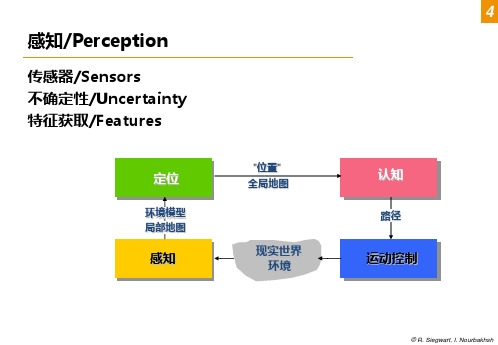
移动机器人需要感知、分析和解释周围的状态 真实环境中的测量是动态变化并产生误差的. 例如:
变化的光照条件/changing illuminations 镜面产生的反射/specular reflections 吸收声光的表面/Light or sound absorbing surfaces 机器人传感器对机器人姿态和机器人环境动力学的交叉敏感度
光学陀螺仪/Optical Gyroscopes
商用开始于80年代初期在飞机上安装使用. 观学陀螺仪/Optical gyroscopes
利用同一光源发射的两个单色束角或激光光束获得 速度(导向)传感器. 一束顺时针行进通过光纤, 另一束绕圆柱体逆时针行进 激光光束沿着旋转方向行进 行进路径偏短-> 表现出较高的频率 两束光频率之差Df 正比于圆柱体的角速度 W 新的固体光学陀螺仪也是基于同样原理采用微加工工艺制作.
© R. Siegwart, I. Nourbakhsh
一般分类/General Classification (1)
/触觉 /轮置电机传感器
/朝向
4.1.1
© R. Siegwart, I. Nourbakhsh
一般分类/General Classification (2)
/地面信标 /主动测距
OmniViSion推出世界首款1/6-inch1080pHDCMOS图像传感器

表 、 听器 、 助 计算 器 、 型无 钥 门禁 、 微 内存 备份 、 小型 玩 具等 微 型 电子 产 品和其 它』 用 而设 计 的这些 新型 巫 固位器 配有 可靠 的 弹簧张 力 ,在 将 电池牢 固 同定在
同位 器 内的同时 确保较 低 的接触 电阻 。
这 种新 型表 而安 装 崮位 器 可接受 所有 大型制 造 商 的 MI 4微 型锂 电池 , 适合 所 有焊接 和 回流操 A1 并 作 。 同位器 采用磷 铜制 造 , 焊 款 m i 推 i VSo
1 6 o 0 0 D C O / 一i h 1 8 p H M S图像 传 感 器 n
O i io eh o g s 日推 出 r 0 2 2 , mnV s nT c nl i 近 i oe V 7 0
R推 出 l3 2 5 1及 I3 2 R 59 R Xhs P a e芯 片组 解 决 方 案
国际整流 器公 司推 出 I 3 2 及 I 3 2 P ae R 5 1 R 5 9X h s
术 ,得 以在 任意 近距 离 的投影 平面 上提 供弹 性 多样
化 的显 示 画面 。另根 据知 名并 具权 威性 的市 场研 究 机构报 告指 ,微 型投影 机市 场年 增率 将于 未来 五 年 中高 达 5 %;创 惟科 技 与 Sni t 同开 发之 解 0 yda 共 n
供统 一 的 、 证有 效 的设 计 实现流 程 , 验 支持 涵盖各 种 应用 的 T MC令定 制设 计需 求 。 S 作 为 全球 最 大 的专 业 半 导 体 晶 圆厂 ,S T MC专
注 于 纳米 技 术 和百 万 门级 I c设 计所 需 的 开发 能 力
与 实现 。L k r ae 系统提 供容 易使用 的 自动化 工具 , 缩 短处 理 高质 量且 复杂 的全定 制 电路版 图时 间 。
REQUIRED VISION EXAMINATIONS AND VISION 所需的视野检查及视野

17% 15%
3%
Kemper, P., MD, MH, MS; Clark, S., MPH. Preschool Vision Screening in Pediatric Practices: Clinical Pediatrics, April 2019.
14
Follow Up After Failed Vision Screenings
9
VISION SCREENING
• Examiner tests the accuracy of vision in each eye and possibly whether the eyes are straight and working together. A screening detects potential problems but does not diagnose them.
Ciner E, Dobson V, Schmidt P, et al. A Survey of vision screening policy of preschool children in the United States. Surv Opthalmol 2019 March-April: 43(5): 445-457.
6
Vision, Child Development, and Education
• “Impaired vision can affect a child’s cognitive, emotional, neurologic and physical development by potentially limiting the range of experiences and kinds of information to which the child is exposed.”
基于球形加权结构相似度的全向视频编码率失真优化方法

Abstract: Aiming at the shortcomings of the coding rate distortion model in traditional video coding, considering the characteristics of equal rectangular omnidirectional video, a method of omnidirectional video coding rate distortion optimization based on spherical weighted structural similarity (WS-SSIM) was proposed. By considering the distortion of the internal structural similarity of the projection plane and the relationship between the spherical distortion and the projection plane distortion, the “spherical weighted structural similarity” was proposed to describe the degree of distortion of the planar omnidirectional image local block relative to the viewing sphere, which was applied to the rate-distortion optimization process of omnidirectional video coding and adaptive selection of quantization parameters to improve vision-based coding efficiency. The experimental results show that compared with the HEVC video coding standard HM16.9 test platform, the proposed method can save an average of 24.48% code rate under the same visual quality, which indicates that the method has significant performance for improving the omnidirectional video coding rate distortion performance. Key words: omnidirectional video coding, weighted-to-spherically-uniform structural similarity, rate distortion optimization, adaptive quantization parameter selection
- 1、下载文档前请自行甄别文档内容的完整性,平台不提供额外的编辑、内容补充、找答案等附加服务。
- 2、"仅部分预览"的文档,不可在线预览部分如存在完整性等问题,可反馈申请退款(可完整预览的文档不适用该条件!)。
- 3、如文档侵犯您的权益,请联系客服反馈,我们会尽快为您处理(人工客服工作时间:9:00-18:30)。
Omnidirectional VisionShree K.NayarDepartment of Computer ScienceColumbia UniversityNew York,NY10027,USAnayar@AbstractConventional video cameras have limitedfields of view that make them re-strictive in a variety of vision applications.There are several ways to enhancethefield of view of an imaging system.However,the entire imaging systemmust have a single effective viewpoint to enable the generation of pure per-spective images from a sensed image.A camera with a hemisphericalfieldof view is presented.Two such cameras can be placed back-to-back,withoutviolating the single viewpoint constraint,to arrive at a truly omnidirectionalsensor.The implications of such a sensor for computational vision are ex-plored.Results are presented on the software generation of pure perspectiveimages from an omnidirectional image,given any user-selected viewing di-rection and magnification.The paper concludes with a discussion on thespatial resolution of the proposed camera.1IntroductionConventional imaging systems are quite limited in theirfield of view.Is it feasible to devise a video camera that can,at any instant in time,“see”in all directions?Such an omnidirectional camera would have an impact on a variety of applications,including autonomous navigation,video surveillance,video conferencing,virtual reality and site modelling.Our approach to omnidirectional image sensing is to incorporate reflecting surfaces (mirrors)into conventional imaging systems.This is what we refer to as catadioptric image formation[16].There are a few existing implementations that are based on this approach to image sensing(see[21],[4],[15],[27],[8],[7],[28],[2],[13],[14],[24],[16] and[18]).As noted in[21],[28]and[14],in order to compute pure perspective images from a wide-angle image,the catadioptric imaging system must have a single center of projection(viewpoint).In[17][1],the complete class of catadioptric systems that satisfy the single viewpoint constraint is derived.Since we are interested in the development of a practical omnidirectional camera,two additional conditions are imposed.First,the camera should be easy to implement and calibrate.Second,the mapping from world coordinates to image coordinates must be simple enough to permit fast computation of perspective and panoramic images.This article was also published in the proceedings of the1997International Symposium on Robotics Re-search,held in Japan.2British Machine Vision ConferenceWe begin by reviewing the state-of-the-art in wide-angle imaging and discuss the merits and drawbacks of existing approaches.Next,we present an omnidirectional video camera[16]that satisfies the single viewpoint constraint,is easy to implement,and pro-duces images that are efficient to manipulate.We have implemented several prototypes of the proposed camera,each one designed to meet the requirements of a specific applica-tion.Results on the mapping of omnidirectional images to perspective ones are presented. In[20],a software system is described that generates a large number of perspective and panoramic video streams from an omnidirectional video input.More recently,the pro-posed omnidirectional camera has been used for robust computation of egomotion[6]. Also,planar and curved mirrors have been used to develop compact binocular stereo sys-tems[18].2Single ViewpointpanoramicFigure1:A truly omnidirectional image sensor views the world through an entire“sphere of view”as seen from its center of projection.The single viewpoint permits the construction of pure perspective images(computed by planar projection)or a panoramic image(computed by cylindrical projection).The merits of having a single center of projection(viewpoint)have been emphasized by Rees[21],Yamazawa et al.[28]and Nalwa[14].Consider an image acquired by a sensor that can view the world in all directions from a single effective pinhole(see Figure 1).From such an omnidirectional image,pure perspective images can be constructed by mapping sensed brightness values onto a plane placed at any distance(effective focal length)from the viewpoint,as shown in Figure1.Any image computed in this manner preserves linear perspective geometry.Images that adhere to perspective projection are desirable from two standpoints;they are consistent with the way we are used to seeing images,and they lend themselves to further processing by the large body of work in computational vision that assumes linear perspective projection.British Machine Vision Conference3 3State of the ArtBefore we present our omnidirectional camera,a review of existing imaging systems that seek to achieve widefields of view is in order.An excellent overview of some of the previous work can be found in[14].FOV(c)(a)(b)Figure2:(a)A conventional imaging system and its limitedfield of view.A largerfield of view may be obtained by(b)rotating the imaging system about its center of projection,(c)appending a fish-eye lens to the imaging system,and(d)imaging the scene through a mirror.3.1Traditional Imaging SystemsMost imaging systems in use today comprise of a video camera,or a photographicfilm camera,attached to a lens.The image projection model for most camera lenses is per-spective with a single center of projection.Since the imaging device(CCD array,for instance)is offinite size and the camera lens occludes itself while receiving incoming rays,the lens typically has a limitedfield of view that corresponds to a small cone rather than a hemisphere(see Figure2(a)).Atfirst thought,it may appear that a largefield can be sensed by packing together a number of cameras,each one pointing in a different direction.However,since the centers of projection reside inside their respective lenses, such a configuration proves infeasible.3.2Rotating Imaging SystemsAn obvious solution is to rotate the entire imaging system about its center of projection, as shown in Figure2(b).The sequence of images acquired by rotation are“stitched”together to obtain a panoramic view of the scene.Such an approach has been proposed by several investigators(see[5],[11],[9],[29],for examples).Of these the most novel is the system developed by Krishnan and Ahuja[9]which uses a camera with a non-frontal image detector to scan the world.4British Machine Vision ConferenceThefirst disadvantage of any rotating imaging system is that it requires the use of moving parts and precise positioning.A more serious drawback lies in the total time required to obtain an image with enhancedfield of view.This restricts the use of rotating systems to static scenes and non-real-time applications.3.3Fish-Eye LensesAn interesting approach to wide-angle imaging is based on thefish-eye lens(see[25], [23],[12]).Such a lens is used in place of a conventional camera lens and has a very short focal length that enables the camera to view objects within a hemisphere or more (see Figure2(c)).The use offish-eye lenses for wide-angle video has been advocated in [19],[10]and[26],among others.It turns out that it is difficult to design afish-eye lens that ensures that all incoming principal rays intersect at a single point to yield afixed viewpoint(see[14]for details). This is indeed a problem with commercialfish-eye lenses,including,Nikon’s Fisheye-Nikkor8mm f/2.8lens.In short,the acquired image does not permit the construction of distortion-free perspective images of the viewed scene(though constructed images may prove good enough for some visualization applications).In addition,to capture a hemi-spherical view,thefish-eye lens must be quite complex and large,and hence expensive. Furthermore,in our quest for a truly omnidirectional sensor,we are physically restricted in placing twofish-eye imaging systems back-to-back to image the complete sphere of view;the two viewpoint loci reside inside their respective lenses and hence cannot be brought close to one another.However,in applications where a single viewpoint is not critical,a back-to-back configuration such as the one implemented by Slater[22]can be used.3.4Catadioptric SystemsAs shown in Figure2(d),a catadioptric imaging system uses a reflecting surface to en-hance thefield of view.However,the shape,position,and orientation of the reflecting surface are related to the viewpoint and thefield of view in a complex manner.While it is easy to construct a configuration which includes one or more mirrors that dramatically increase thefield of view of the imaging system,it is harder to keep the effective view-pointfixed in space.Examples of catadioptric image sensors can be found in[21],[4], [27],[8],[28],[2],[13]and[14].A recent theoretical result[1]reveals the complete class of catadioptric imaging systems that satisfy the single viewpoint constraint.This general solution has enabled us to evaluate the merits and drawbacks of previous implementations as well as suggest new ones[1].Here,we will briefly review previous approaches.In[27]and[2],a conical mirror is used in conjunction with a perspective lens.Though this provides a panoramic view, the single viewpoint constraint is not satisfied.The result is a viewpoint locus that hangs like a halo over the mirror.In[8],[2]and[13],a spherical mirror was used with a perspective lens.Again,the result is a large locus of viewpoints rather than a single point. Hyperboloidal,paraboloidal and ellipsoidal mirrors have been used in the implementation of“all-sky”photographic cameras dating back to the late1950’s(examples can be found in[4]).In most of these implementations,the single viewpoint constraint does not seem to have been a major consideration.British Machine Vision Conference5 Rees[21]appears to have been thefirst to use a hyperboloidal mirror with a perspec-tive lens placed at its external focus to achieve a single viewpoint video camera system.A similar implementation was recently proposed in[28].The hyperboloidal solution is a useful one.However,the sensor must be implemented and calibrated with care.More recently,Nalwa[14]has proposed a panoramic sensor that includes four planar mirrors that form the faces of a pyramid.Four separate imaging systems are used,each one placed above one of the faces of the pyramid.The optical axes of the imaging systems and the angles made by the four planar faces are adjusted so that the four viewpoints produced by the planar mirrors coincide.The result is a sensor that has a single viewpoint and a panoramicfield of view of approximately.4Omnidirectional CameraWhile all of the above approaches use mirrors placed in the view of perspective lenses,we approach the problem using an orthographic lens.It is easy to see that if image projection is orthographic rather than perspective,the geometrical mappings between the image,the mirror and the world are invariant to translations of the mirror with respect to the imaging system.Consequently,both calibration as well as the computation of perspective images is greatly simplified.There are several ways to achieve orthographic projection.Most of these are described in[16].The one that we have adopted in many of our implementations is the use of an inexpensive relay lens in front of an off-the-shelf perspective lens.The relay lens not only converts the imaging system to an orthographic one but can also be used to undo more subtle optical effects such as coma and astigmatism[3]produced by curved mirrors.Since orthographic projection is rotationally symmetric about the optical axis,all we need to determine is the cross-section of the reflecting surface.The mirror is then the solid of revolution obtained by sweeping the cross-section about the axis of orthographic projection.A detailed derivation of the mirror shape for orthographic projection is given in[16].Not surprisingly,the mirror that guarantees a single viewpoint is a paraboloid with cross-section:(1) where,is the parameter of paraboloid.Paraboloidal mirrors are frequently used to converge an incoming set of parallel rays at a single point(the focus),or to generate a collimated light source from a point source (placed at the focus).In both these cases,the paraboloid is a concave mirror that is reflective on its inner surface.In our case,the paraboloid is reflective on its outer surface (convex mirror);all incoming principle rays are orthographically reflected by the mirror but can be extended to intersect at its focus,which serves as the viewpoint.Note that a concave paraboloidal mirror can also be used.This solution is less desirable to us since incoming rays with large angles of incidence could be self-occluded by the mirror.As shown in Figure3,the parameter of the paraboloid is its radius at.The distance between the vertex and the focus is.Therefore,determines the size of the paraboloid that,for any given orthographic lens system,can be chosen to maximize resolution.6British Machine Vision ConferenceFigure3:For orthographic projection,the solution is a paraboloid with the viewpoint located at the focus.Orthographic projection makes the geometric mappings between the image,the paraboloidal mirror and the world invariant to translations of the mirror.This greatly simplifies calibration and the computation of perspective images from paraboloidal ones.5Field of ViewAs the extent of the paraboloid increases,so does thefield of view of the catadioptric sen-sor.It is not possible,however,to acquire the entire sphere of view since the paraboloid itself must occlude the world beneath it.This brings us to an interesting practical consid-eration:Where should the paraboloid be terminated?Note that(2) Hence,if we cut the paraboloid at the plane,thefield of view exactly equals the upper hemisphere(minus the solid angle subtended by the imaging system itself).If a field of view greater than a hemisphere is desired,the paraboloid can be terminated below the plane.If only a panorama is of interest,an annular section of the paraboloid may be obtained by truncating it below and above the plane.In our prototypes,we have chosen to terminate the parabola at the plane.This proves advantageous in applications in which the complete sphere of view is desired,as shown in Figure4.Since the paraboloid is terminted at the focus,it is possible to place two identical catadioptric cameras back-to-back such that their foci(viewpoints)coincide. Thus,we have a truly omnidirectional sensor,one that is capable of acquiring an entire sphere of view at video rate.British Machine Vision Conference7Figure4:If the paraboloid is cut by the horizontal plane that passes through its focus,thefield of view of the catadioptric system exactly equals the upper hemisphere.This allows us to place two catadioptric sensors back-to-back such that their foci(viewpoints)coincide.The result is a truly omnidirectional sensor that can acquire the entire sphere of view.The shaded regions are parts of thefield of view where the sensor sees itself.6ImplementationSeveral versions of the proposed omnidirectional sensor have been built,each one geared towards a specific application.The applications we have in mind include video teleconfer-encing,remote surveillance and autonomous navigation.Figure5shows and details the different sensors and their components.The basic components of all the sensors are the same;each one includes a paraboloidal mirror,an orthographic lens system and a CCD video camera.The sensors differ primarily in their mechanical designs and their attach-ments.Figure5(d)shows a back-to-back implementation that is capable of acquiring the complete sphere of view.The use of paraboloidal mirrors virtually obviates calibration.All that is needed are the image coordinates of the center of the paraboloid and its radius.Both these quan-tities are measured in pixels from a single omnidirectional image.We have implemented software for the generation of perspective images.First,the user specifies the viewing direction,the image size and effective focal length(zoom)of the desired perspective image(see Figure1).Again,all these quantities are specified in pixels.For each three-dimensional pixel location(,,)on the desired perspective image plane,its line of sight with respect to the viewpoint is computed in terms of its polar and azimuthal angles:(3) This line of sight intersects the paraboloid at a distance from its focus(origin),which is computed using the following spherical expression for the paraboloid:(4) The brightness(or color)at the perspective image point(,,)is then the same as that8British Machine Vision Conference(a)(b)(c)(d)Figure5:Four implementations of catadioptric omnidirectional video cameras that use paraboloidal mirrors.(a)This compact sensor for teleconferencing uses a1.1inch diameter paraboloidal mirror,a Panasonic GP-KR222color camera,and Cosmicar/Pentax C6Z1218zoom and close-up lenses to achieve orthography.The transparent spherical dome minimizes self-obstruction of thefield of view.(b)This camera for navigation uses a2.2inch diameter mirror, a DXC-950Sony color camera,and a Fujinon CVL-713zoom lens.The base plate has an attach-ment that facilitates easy mounting on mobile platforms.(c)This sensor for surveillance uses a1.6 inch diameter mirror,an Edmund Scientific55mm F/2.8telecentric(orthographic)lens and a Sony XR-77black and white camera.The sensor is lightweight and suitable for mounting on ceilings and walls.(d)This sensor is a back-to-back configuration that enables it to sense the entire sphere of view.Each of its two units is identical to the sensor in(a).British Machine Vision Conference9Figure6:Software generation of perspective images(bottom)from an omnidirectional image (top).Each perspective image is generated using user-selected parameters,including,viewing di-rection(line of sight from the viewpoint to the center of the desired image),effective focal length (distance of the perspective image plane from the viewpoint of the sensor),and image size(number of desired pixels in each of the two dimensions).It is clear that the computed images are indeed perspective.10British Machine Vision Conferenceat the omnidirectional image point(5) The above computation is repeated for all points in the desired perspective image.Fig-ure6shows an omnidirectional image(512x480pixels)and several perspective images (200x200pixels each)computed from it.It is worth noting that perspective projection is indeed preserved.For instance,straight lines in the scene map to straight lines in the perspective images while they appear as curved lines in the omnidirectional image.A video-rate version of the above described image generation is detailed in[20].7ResolutionSeveral factors govern the resolution of a catadioptric sensor.The most obvious of these is the spatial resolution due tofinite pixel size.In[17],we have derived a general expression for the spatial resolution of any catadioptric camera.In the case of our paraboloidal mirror,the resolution increases by a factor of4from the vertex()of the paraboloid to the fringe().In many applications,this turns out to be a benefit of using a curved mirror instead of afish-eye lens;often,the panorama is of greater interest than the rest of thefield of view.If a uniform resolution over the entirefield of view is desired,it is of course possible to use image detectors with non-uniform resolution to compensate for the above variation.It should also be mentioned that while all our implementations use CCD arrays with512x480pixels,nothing precludes us from using detectors with1024x1024 or2048x2048pixels that are commercially available at a higher cost.More intriguing are the blurring effects offield curvature,coma and astigmatism that arise due to the aspherical nature of the reflecting surface[3].Since these effects are linear but shift-variant,a suitable set of deblurringfilters could be explored.Alternatively,these effects can be significantly reduced using inexpensive corrective lenses.We have recently used such corrective lenses to obtain excellent results. AcknowledgementsThis work was inspired by the prior work of Vic Nalwa of Lucent Technologies.I have benefitted greatly from discussions with him.I thank Simon Baker and Venkata Peri of Columbia University for their valuable comments on various drafts of this paper.This project was supported in parts by an NSF National Young Investigator Award,an ONR MURI Grant(No.N00014-95-1-0601),and a David and Lucile Packard Fellowship. References[1]S.Baker and S.K.Nayar.Catadioptric Image Formation.Proc.of International Conferenceon Computer Vision,January1998.[2]S.Bogner.Introduction to Panoramic Imaging.Proc.of IEEE SMC Conference,pages3100–3106,October1995.[3]M.Born and E.Wolf.Principles of Optics.London:Permagon,1965.[4]J.R.Charles.How to Build and Use an All-Sky Camera.Astronomy Magazine,April1987.British Machine Vision Conference11 [5]S.E.Chen.QuickTime VR-An Image Based Approach to Virtual Environment Navigation.Computer Graphics:Proc.of SIGGRAPH95,pages29–38,August1995.[6]J.Gluckman and S.K.Nayar.Egomotion and Omnidirectional Cameras.Proc.of Interna-tional Conference on Computer Vision,January1998.[7] A.Goshtasby and W.A.Gruver.Design of a Single-Lens Stereo Camera System.PatternRecognition,26(6):923–937,1993.[8]J.Hong.Image Based Homing.Proc.of IEEE International Conference on Robotics andAutomation,May1991.[9] A.Krishnan and N.Ahuja.Panoramic Image Acquisition.Proc.of IEEE Conf.on ComputerVision and Pattern Recognition(CVPR-96),pages379–384,June1996.[10] D.P.Kuban,H.L.Martin,S.D.Zimmermann,and N.Busico.Omniview Motionless CameraSurveillance System.United States Patent,(5,359,363),October1994.[11]L.McMillan and G.Bishop.Plenoptic Modeling:An Image-Based Rendering -puter Graphics:Proc.of SIGGRAPH95,pages39–46,August1995.[12]K.Miyamoto.Fish Eye Lens.Journal of Optical Society of America,54(8):1060–1061,August1964.[13]J.R.Murphy.Application of Panoramic Imaging to a Teleoperated Lunar Rover.Proc.ofIEEE SMC Conference,pages3117–3121,October1995.[14]V.Nalwa.A True Omnidirectional Viewer.Technical report,Bell Laboratories,Holmdel,NJ07733,U.S.A.,February1996.[15]S.K.Nayar.Sphereo:Recovering depth using a single camera and two specular spheres.Proc.of SPIE:Optics,Illumumination,and Image Sensing for Machine Vision II,November 1988.[16]S.K.Nayar.Catadioptric Omnidirectional Camera.Proc.of IEEE Conf.on Computer Visionand Pattern Recognition,June1997.[17]S.K.Nayar and S.Baker.Catadioptric Image Formation.Proc.of DARPA Image Understand-ing Workshop,May1997.[18]S.A.Nene and S.K.Nayar.Stereo Using Mirrors.Proc.of International Conference onComputer Vision,January1998.[19]S.J.Oh and E.L.Hall.Guidance of a Mobile Robot using an Omnidirectional Vision Naviga-tion System.Proc.of the Society of Photo-Optical Instrumentation Engineers,SPIE,852:288–300,November1987.[20]V.Peri and S.K.Nayar.Generation of Perspective and Panoramic Video from Omnidirec-tional Video.Proc.of DARPA Image Understanding Workshop,May1997.[21] D.W.Rees.Panoramic Television Viewing System.United States Patent,(3,505,465),April1970.[22] D.Slater.Panoramic photography withfish eye lenses.Panorama,International Associationof Panoramic Photographers,13(2,3),1996.[23]J.Slater.Photography with the whole sky lens.American Photographer,October1932.[24] D.Southwell,A.Basu,M.Fiala,and J.Reyda.Panoramic Stereo.Proc.of InternationalConference on Pattern Recognition,August1996.[25]R.W.Wood.Fish-eye views,and vision under water.Philosophical Magazine,12(Series6):159–162,1906.[26]Y.Xiong and K.Turkowski.Creating Image-Based VR Using a Self Calibrating Fisheye Lens.Proc.of IEEE Conf.on Computer Vision and Pattern Recognition,June1997.12British Machine Vision Conference[27]Y.Yagi and S.Kawato.Panoramic Scene Analysis with Conic Projection.Proc.of Interna-tional Conference on Robots and Systems(IROS),1990.[28]K.Yamazawa,Y.Yagi,and M.Yachida.Obstacle Avoidance with Omnidirectional ImageSensor HyperOmni Vision.Proc.of IEEE International Conference on Robotics and Automa-tion,pages1062–1067,May1995.[29]J.Y.Zheng and S.Tsuji.Panoramic Representation of Scenes for Route Understanding.Proc.of the Tenth International Conference on Pattern Recognition,1:161–167,June1990.。