5082-K703-DD000中文资料
5082-K703-GG000中文资料

Features• Low Power Consumption • Industry Standard Size• Industry Standard Pinout • Choice of Character Size7.6 mm (0.30 in), 10 mm (0.40 in), 10.9 mm (0.43 in), 14.2 mm (0.56 in), 20 mm (0.80 in)• Choice of ColorsAlGaAs Red, High Efficiency Red (HER), Yellow, Green• Excellent Appearance Evenly Lighted Segments±50° Viewing Angle• Design FlexibilityCommon Anode or Common CathodeSingle and Dual DigitLeft and Right Hand Decimal Points±1. Overflow Character• Categorized for Luminous IntensityYellow and Green Categorized for ColorUse of Like Categories Yields a Uniform Display• Excellent for Long Digit String Multiplexing DescriptionThese low current seven segment displays are designed for applica-tions requiring low power consumption. They are tested and selected for their excellent low current characteristics to ensure that the segments are matched at low currents. Drive currents as low as 1 mA per segment are available.Pin for pin equivalent displays are also available in a standard current or high light ambient design. The standard current displays are available in all colors and are ideal for most applica-tions. The high light ambient displays are ideal for sunlight ambients or long string lengths. For additional information see the 7.6 mm Micro Bright Seven Segment Displays, 10 mm Seven Segment Displays, 7.6 mm/10.9 mm Seven Segment Displays, 14.2 mm Seven Segment Displays, 20 mm Seven Segment Displays, or High Light Ambient Seven Segment Displays data sheets.Low Current Seven SegmentDisplays Technical Data HDSP-335x SeriesHDSP-555x SeriesHDSP-751x SeriesHDSP-A10x Series HDSP-A80x Series HDSP-A90x Series HDSP-E10x Series HDSP-F10x Series HDSP-G10x Series HDSP-H10x Series HDSP-K12x, K70x Series HDSP-N10x SeriesHDSP-N40x SeriesDevicesAlGaAs HER Yellow Green Package HDSP-HDSP-HDSP-HDSP-Description Drawing A1017511A801A9017.6 mm Common Anode Right Hand Decimal A A1037513A803A9037.6 mm Common Cathode Right Hand Decimal B A1077517A807A9077.6 mm Common Anode ±1. Overflow C A1087518A808A9087.6 mm Common Cathode ±1. Overflow D F10110 mm Common Anode Right Hand Decimal E F10310 mm Common Cathode Right Hand Decimal F F10710 mm Common Anode ±1. Overflow G F10810 mm Common Cathode ±1. Overflow H G10110 mm Two Digit Common Anode Right Hand Decimal X G10310 mm Two Digit Common Cathode Right Hand Decimal Y E100335010.9 mm Common Anode Left Hand Decimal I E101335110.9 mm Common Anode Right Hand Decimal J E103335310.9 mm Common Cathode Right Hand Decimal K E106335610.9 mm Universal ±1. Overflow[1]L H101555114.2 mm Common Anode Right Hand Decimal M H103555314.2 mm Common Cathode Right Hand Decimal N H107555714.2 mm Common Anode ±1. Overflow O H108555814.2 mm Common Cathode ±1. Overflow P K121K70114.2 mm Two Digit Common Anode Right Hand Decimal R K123K70314.2 mm Two Digit Common Cathode Right Hand Decimal S N10020 mm Common Anode Left Hand Decimal Q N101N40120 mm Common Anode Right Hand Decimal T N103N40320 mm Common Cathode Right Hand Decimal U N10520 mm Common Cathode Left Hand Decimal V N106N40620 mm Universal ±1. Overflow[1]W Note:1. Universal pinout brings the anode and cathode of each segment’s LED out to separate pins. See internal diagrams L or W.Part Numbering System5082-x xx x-x x x xxHDSP-x xx x-x x x xxMechanical Options[1]00: No mechanical optionColor Bin Options[1,2]0: No color bin limitationMaximum Intensity Bin[1,2]0: No maximum intensity bin limitationMinimum Intensity Bin[1,2]0: No minimum intensity bin limitationDevice Configuration/Color[1]G: GreenDevice Specific Configuration[1]Refer to respective datasheetPackage[1]Refer to Respective datasheetNotes:1. For codes not listed in the figure above, please refer to the respective datasheet or contact your nearest Agilent representative fordetails.2. Bin options refer to shippable bins for a part-number. Color and Intensity Bins are typically restricted to 1 bin per tube (excep-tions may apply). Please refer to respective datasheet for specific bin limit information.Package DimensionsPackage Dimensions (cont.)Package Dimensions (cont.)*The Side View of package indicates Country of Origin.Package Dimensions (cont.)Package Dimensions (cont.)Package Dimensions (cont.)Internal Circuit DiagramInternal Circuit Diagram (cont.)Absolute Maximum RatingsAlGaAs Red - HDSP-HERA10X/E10X/H10X HDSP-751X/Yellow GreenK12X/N10X/N40X335X/555X/HDSP-A80X HDSP-A90X Description F10X, G10X Series K70X Series Series Series Units Average Power per Segment or DP375264mW Peak Forward Current per 45mA Segment or DPDC Forward Current per15[1]15[2]mA Segment or DPOperating Temperature Range-20 to +100-40 to +100°C Storage Temperature Range -55 to +100°C Reverse Voltage per Segment 3.0V or DPWave Soldering Temperature for 3Seconds (1.60 mm [0.063 in.] below 250°C seating body)Notes:1. Derate above 91°C at 0.53 mA/°C.2. Derate HER/Yellow above 80°C at 0.38 mA/°C and Green above 71°C at 0.31 mA/°C.Electrical/Optical Characteristics at T A = 25°CAlGaAs RedDeviceSeriesHDSP-Parameter Symbol Min.Typ.Max.Units Test Conditions315600I F = 1 mA A10x3600I F = 5 mA330650I F = 1 mAF10x, G10x3900I F = 5 mA390650I F = 1 mA E10x Luminous Intensity/Segment[1,2]I Vµcd(Digit Average)3900I F = 5 mA400700I F = 1 mAH10x, K12x4200I F = 5 mA270590I F = 1 mAN10x, N40x3500I F = 5 mA1.6I F = 1 mAForward Voltage/Segment or DP V F 1.7V I F = 5 mA1.82.2I F = 20 mA PkAll Devices Peak WavelengthλPEAK645nmDominant Wavelength[3]λd637nmReverse Voltage/Segment or DP[4]V R 3.015V I R = 100 µATemperature Coefficient of∆V F/°C-2 mV mV/°CV F/Segment or DPA10x255F10x, G10x320E10x340Thermal Resistance LED RθJ-PIN°C/W/SegH10x, K12x Junction-to-Pin400N10x, N40x430High Efficiency RedDeviceSeriesHDSP-Parameter Symbol Min.Typ.Max.Units Test Conditions160270I F = 2 mA 751x1050I F = 5 mA200300I F = 2 mA Luminous Intensity/Segment[1,2]I V mcd(Digit Average)1200I F = 5 mA335x, 555x,K70x270370I F = 2 mA1480I F = 5 mA1.6I F = 2 mAForward Voltage/Segment or DP V F 1.7V I F = 5 mA2.1 2.5I F = 20 mA Pk All Devices Peak WavelengthλPEAK635nmDominant Wavelength[3]λd626nmReverse Voltage/Segment or DP[4]V R 3.030V I R = 100 µATemperature Coefficient of∆V F/°C-2mV/°CV F/Segment or DP751x200335x Thermal Resistance LED RθJ-PIN280°C/WJunction-to-Pin555x, K70x345YellowDeviceSeriesHDSP-Parameter Symbol Min.Typ.Max.Units Test Conditions Luminous Intensity/Segment[1,2]250420I F = 4 mA(Digit Average)I V mcd1300I F = 10 mA1.7I F = 4 mAForward Voltage/Segment or DP V F 1.8V I F = 5 mA A80x2.1 2.5I F = 20 mA PkPeak WavelengthλPEAK583nmDominant Wavelength[3,5]λd581.5585592.5nmReverse Voltage/Segment or DP[4]V R 3.030V I R = 100 µATemperature Coefficient of∆V F/°C-2mV/°CV F/Segment or DPThermal Resistance LED RθJ-PIN200°C/WJunction-to-PinGreenDeviceSeriesHDSP-Parameter Symbol Min.Typ.Max.Units Test Conditions Luminous Intensity/Segment[1,2]250475I F = 4 mA(Digit Average)I V mcd1500I F = 10 mA1.9I F = 4 mAForward Voltage/Segment or DP V F 2.0V I F = 10 mA A90x2.1 2.5I F = 20 mA PkPeak WavelengthλPEAK566nmDominant Wavelength[3,5]λd571577nmReverse Voltage/Segment or DP[4]V R 3.030V I R = 100 µATemperature Coefficient of∆V F/°C-2mV/°CV F/Segment or DPThermal Resistance LED RθJ-PIN200°C/WJunction-to-PinNotes:1. Device case temperature is 25°C prior to the intensity measurement.2. The digits are categorized for luminous intensity. The intensity category is designated by a letter on the side of the package.3. The dominant wavelength, λd, is derived from the CIE chromaticity diagram and is the single wavelength which defines the color of thedevice.4. Typical specification for reference only. Do not exceed absolute maximum ratings.5. The yellow (HDSP-A800) and Green (HDSP-A900) displays are categorized for dominant wavelength. The category is designated by anumber adjacent to the luminous intensity category letter.AlGaAs RedIntensity Bin Limits (mcd)AlGaAs RedHDSP-A10xIV Bin Category Min.Max.E0.3150.520F0.4280.759G0.621 1.16H0.945 1.71I 1.40 2.56J 2.10 3.84K 3.14 5.75L 4.708.55HDSP-E10x/F10x/G10xIV Bin Category Min.Max.D0.3910.650E0.5320.923F0.755 1.39G 1.13 2.08H 1.70 3.14HDSP-H10x/K12xIV Bin Category Min.Max.C0.4150.690D0.5650.990E0.810 1.50F 1.20 2.20G 1.80 3.30H 2.73 5.00I 4.097.50HDSP-N10xIV Bin Category Min.Max.A0.2700.400B0.3250.500C0.4150.690D0.5650.990E0.810 1.50F 1.20 2.20G 1.80 3.30H 2.73 5.00I 4.097.50Intensity Bin Limits (mcd), continued HERHDSP-751xIV Bin Category Min.Max.B0.1600.240C0.2000.300D0.2500.385E0.3150.520F0.4280.759G0.621 1.16HDSP-751xIV Bin Category Min.Max.B0.2400.366C0.3000.477D0.3910.650E0.5320.923F0.755 1.39G 1.13 2.08H 1.70 3.14HDSP-555x/K70xIV Bin Category Min.Max.A0.2700.400B0.3250.500C0.4150.690D0.5650.990E0.810 1.50F 1.20 2.20G 1.80 3.30H 2.73 5.00I 4.097.50Intensity Bin Limits (mcd), continued YellowHDSP-A80xIV Bin Category Min.Max.D0.2500.385E0.3150.520F0.4250.760G0.625 1.14H0.940 1.70I 1.40 2.56J 2.10 3.84K 3.14 5.76L 4.718.64M7.0713.00N10.6019.40O15.9029.20P23.9043.80Q35.8065.60GreenHDSP-A90xIV Bin Category Min.Max.E0.3150.520F0.4250.760G0.625 1.14H0.940 1.70I 1.40 2.56J 2.10 3.84K 3.14 5.76L 4.718.64M7.0713.00N10.6019.40O15.9029.20P23.9043.80Q35.8065.60Electrical/OpticalFor more information on electrical/optical characteristics, please see Application Note 1005.Contrast Enhancement For information on contrast enhancement, please see Application Note 1015.Soldering/Cleaning Cleaning agents from the ketone family (acetone, methyl ethyl ketone, etc.) and from the chorinated hydrocarbon family (methylene chloride, trichloro-ethylene, carbon tetrachloride, etc.) are not recommended for cleaning LED parts. All of these various solvents attack or dissolve the encapsulating epoxies used to form the package of plastic LED parts.For information on soldering LEDs, please refer to Application Note 1027.Note:All categories are established for classification of products. Productsmay not be available in all categories. Please contact your localAgilent representatives for further clarification/information.Color Categories/semiconductorsFor product information and a complete list ofdistributors, please go to our web site.For technical assistance call:Americas/Canada: +1 (800) 235-0312 or(916) 788 6763Europe: +49 (0) 6441 92460China: 10800 650 0017Hong Kong: (+65) 6271 2451India, Australia, New Zealand: (+65) 6271 2394Japan: (+81 3) 3335-8152(Domestic/International), or0120-61-1280(Domestic Only)Korea: (+65) 6271 2194Malaysia, Singapore: (+65) 6271 2054Taiwan: (+65) 6271 2654Data subject to change.Copyright © 2005 Agilent Technologies, Inc.Obsoletes 5988-8412ENJanuary 19, 20055989-0080EN。
HMMB-008 百兆模块

WAIN 10-41101 017 210 0101101 017 210 0301101 017 210 0401101 017 210 0601101 017 210 0801101 017 210 0901101 017 210 1001101 017 220 0101101 017 220 0301101 017 220 0401101 017 220 0601101 017 220 0801101 017 220 0901101 017 220 1001CDGF-0.25CDGF-0.37CDGF-0.50CDGF-0.75CDGF-1.0CDGF-1.5CDGF-2.5CDGM-0.25CDGM-0.37CDGM-0.50CDGM-0.75CDGM-1.0CDGM-1.5CDGM-2.5公订货号订货号母插针针数依据 EN 61 984 的电气数据 -额定电流 -额定电压 -额定脉冲电压-污染程度表面处理材料-绝缘体 -外部导体接触电阻温度范围依据UL 94 的阻燃等级表面处理卡口范围2x4+屏蔽10A 50V 0.8kV 3聚碳酸酯锌合金≤4mΩ-40℃...+85℃V0钝化5-12 mmDIN EN 60 664DIN EN 61 984接插件针数绝缘电阻材料工作温度范围依据UL 94 的阻燃等级可拔插次数规范技术参数规范适配器模块百兆插芯冷压针1≥1010Ω聚碳酸酯-40℃...+125℃V0≥500冷压连接 -mm 2 -AWG镀金0.14-2.5 mm 226-1450V 10A 插芯HMMB-008 百兆模块插芯公母型号HMMB-008-MC HMMB-008-FC 订货号129 008 010 0503 129 008 020 0503百兆插芯 冷压连接 冷压针需另外订购适配器模块需另外订购插芯公母型号HMB.C-M HMB.C-F 订货号129 000 001 0001129 000 002 0001适配器模块N EW可与框架及其他所有模块产品组合使用冷压针接触电阻≤3mΩ镀金10A 冷压针工具冷压钳退针器压接线径0.14-4mm ²型号TL02G订货号198 001 001 0011适用范围10A冷压针型号TL00订货号198 001 000 0001更多10A冷压针请详情参见第13-02,第13-02页.注意事项:冷压压接的工具关系到产品的品质稳定性,请选择我司认证的工具。
美国Eaton公司KDB3200W型号的完整包装电弧保护器说明说明书
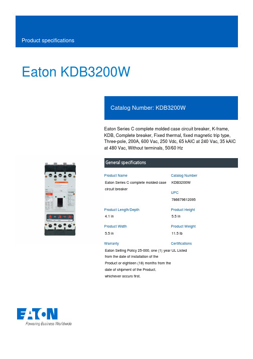
Eaton KDB3200WEaton Series C complete molded case circuit breaker, K-frame, KDB, Complete breaker, Fixed thermal, fixed magnetic trip type, Three-pole, 200A, 600 Vac, 250 Vdc, 65 kAIC at 240 Vac, 35 kAIC at 480 Vac, Without terminals, 50/60 HzGeneral specificationsEaton Series C complete molded case circuit breakerKDB3200W 7866796120954.1 in5.5 in5.5 in 11.5 lb Eaton Selling Policy 25-000, one (1) year from the date of installation of the Product or eighteen (18) months from the date of shipment of the Product, whichever occurs first.UL Listed Product NameCatalog Number UPCProduct Length/Depth Product Height Product Width Product Weight WarrantyCertificationsSeries C35 kAIC at 480 Vac65 kAIC at 240 VacKKDB50 to 60 HzComplete breakerWithout terminals600 Vac, 250 Vdc200 AFixed thermal, fixed magnetic Three-pole UL listed 100%-rated molded case circuit breakersApplication of Tap Rules to Molded Case Breaker Terminals Application of Multi-Wire Terminals for Molded Case Circuit BreakersCircuit breaker motor operators product aidMotor protection circuit breakers product aidPower metering and monitoring with Modbus RTU product aid Current limiting Series C molded case circuit breakers product aid Plug-in adapters for molded case circuit breakers product aid StrandAble terminals product aidMulti-wire lugs product aidMOEM MCCB Product Selection GuideBreaker service centersMolded case circuit breakers catalogEaton's Volume 4—Circuit ProtectionInstallation Instructions for DK, KDB, KD, HKD, KDC, KW, HKW, KWC, CKD, CHKD Circuit Breakers and Molded Case SwitchesInstruction Leaflet for the KES 310+ Electronic Trip UnitCircuit Breakers ExplainedCircuit breakers explainedSeries C F-Frame molded case circuit breakersF-Frame 310+ Molded-case circuit breakers 15-225ASeries C J-Frame molded case circuit breakers time current curves MOEM MCCB product selection guideSeries C G-Frame molded case circuit breakers time current curves Eaton Specification Sheet - KDB3200WSelling Policy 25-000 - Distribution and Control Products and ServicesSeriesInterrupt ratingFrameCircuit breaker type Frequency ratingCircuit breaker frame type TerminalsVoltage rating Amperage RatingTrip TypeNumber of poles Application notesBrochuresCatalogsInstallation instructions MultimediaSpecifications and datasheets Warranty guidesEaton Corporation plc Eaton House30 Pembroke Road Dublin 4, Ireland © 2023 Eaton. All Rights Reserved. Eaton is a registered trademark.All other trademarks areproperty of their respectiveowners./socialmedia。
TT Electronics WDBR系列超低配件电阻说明书
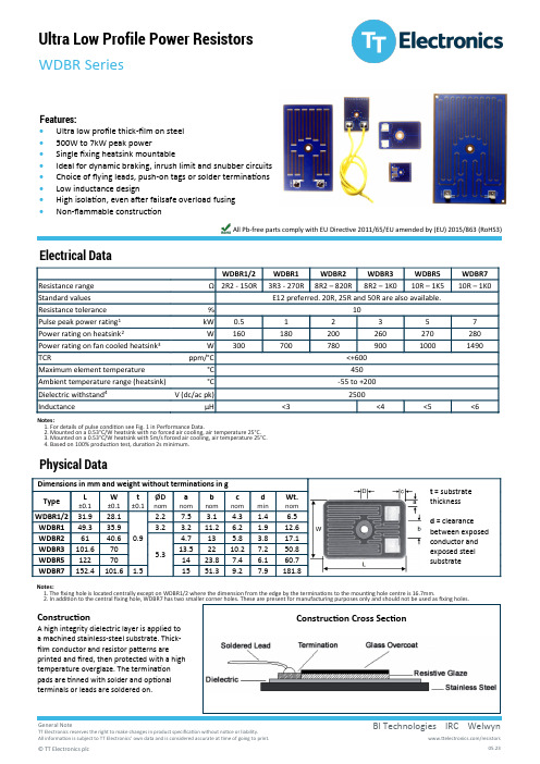
General NoteElectrical DataFeatures:• Ultra low profile thick -film on steel • 500W to 7kW peak power• Single fixing heatsink mountable• Ideal for dynamic braking, inrush limit and snubber circuits • Choice of flying leads, push -on tags or solder terminations • Low inductance design• High isolation, even after failsafe overload fusing •Non -flammable constructionAll Pb -free parts comply with EU Directive 2011/65/EU amended by (EU) 2015/863 (RoHS3)Physical DataConstructionA high integrity dielectric layer is applied to a machined stainless -steel substrate. Thick -film conductor and resistor patterns are printed and fired, then protected with a high temperature overglaze. The termination pads are tinned with solder and optional terminals or leads are soldered on.Notes:1. For details of pulse condition see Fig. 1 in Performance Data.2. Mounted on a 0.53°C/W heatsink with no forced air cooling, air temperature 25°C.3. Mounted on a 0.53°C/W heatsink with 5m/s forced air cooling, air temperature 25°C.4. Based on 100% production test, duration 2s minimum.Notes:1. The fixing hole is located centrally except on WDBR1/2 where the dimension from the edge by the terminations to the mounting hole centre is 16.7mm.2. In addition to the central fixing hole, WDBR7 has two smaller corner holes. These are present for manufacturing purposes only and should not be used as fixing holes.Construction Cross SectionGeneral NoteTermination OptionsWDBR Size Terminal Height, TH Terminal Width, TW Terminal Thickness, TTPerformance DataNote:Two options exist for solder type. The standard is SnAg (96SC) which is Pb -free and the second (HT) is high temperature HMP alloy which is Pb -bearing. Both are RoHS compliant, but the second relies on the RoHS exemption for high temperature solders and is targeted at specialist high temperature applications.Fig. 1 Duty Cycle WaveformFig. 2 Temperature De -ratingGeneral NoteApplication NotesA heatsink with thermal resistance ≤0.53°C/W will enable the component to operate at its continuous power rating. Sufficient thermal grease (e.g. Dow Corning DC340) to give void -free coverage, or a 0.5mm thick compliant thermal pad (e.g. T Global TG -X) should be used and the heatsink should have a surface finish of <6.3μm with flatness of <0.05mm. The resistor should be mounted using an appropriate bolt as listed in the table below. This should be tightened so as to bring the whole area of the steel substrate into intimate contact with the heatsink. The unmounted part is slightly bowed so that the centre is above the edges. Inadequate tightening will leave the centre out of contact with the heatsink, whilst over tightening can cause the edges to rise. The tightening torque required will depend on the fixings and heatsink used, but typical figures are given for guidance.Maximum Peak CurrentWDBR resistors will fail safe (open circuit) under overload fault conditions and still maintain a 1kV dielectric withstand.Soldering of solder pad (termination I) variants requires the use of a hot plate. Hand solder process recommendations are available.WDBR resistors may be customised in various ways including: • Alternative shapes and dimensions up to 406mm x 406mm• Integration of temperature measurement elements and thermal cutouts • Alternative ohmic values and tolerances • Increased dielectric withstand voltage • Custom braking resistors• Integration of multiple power resistorsFor a similar product with UL508 recognition see WDBR -UL: https:///TTElectronics/media/ProductFiles/Datasheet/WDBR -UL.pdfOrdering ProcedureExample: WDBR2-100RKLW (WDBR2 with standard solder and flying lead terminations, 100 ohms ±10%, Pb-free)R2General Note。
PC7032C-12M中文资料
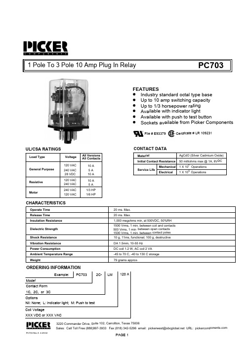
1 Pole To 3 Pole 10 Am p Plug In RelayFEATURESIndustry standard octal type ba se Up to 10 amp switching capaci ty Available with indicator lightUp to 1/3 horsepower rating Available with push to test butt onSockets available from Picker C omponentsPC703Load TypeGeneral PurposeResistive MotorVoltage 120 VAC 240 VAC 28 VDC 240 VAC 120 VACAll Versions 10 A 5 A 10 A 1/3 HP 1/6 HPUL/CSA RATINGSCONTACT DATAMaterialInitial Contact Resistance Service LifeMechanical ElectricalAgCdO (Silver Cadmium Oxide)50 milliohms max @ 1A, 6VDC 1 X 1071 X 105CHARACTERISTICSOperate Time 20 ms. Max.Release Time Insulation Resistance 20 ms. Max.1,000 megohms min, at 500VDC, 50%RH Dielectric Strength 1500 Vrms, 1 min. between coil and contacts 500 Vrms, 1 min. between open contacts Shock Resistance 10 g, 11ms, functional; 100 g, destructive Vibration Resistance DA 1.5mm, 10-55 Hz Power Consumption DC coil 1.2 W, AC coil 2 VA Ambient Temperature Range -45 to 70 C, -40 to 130 C storage Weight79 grams approx.120 VAC 240 VAC 10 A 5 A Operations OperationsSales: Call Toll Free (888)997-3933 Fax (818) 342-5296 email: pickerwest@ URL: 3220 Commander Drive, Suite 102, Carrollton, T exas 75006All ContactsPC703 Rev A 4-29-021500 Vrms, 1 min. between contact poles PAGE 1File # E93379Certificate # LR 109231ORDERING INFORMATIONExample:PC703Model LM Coil Voltage2C-Contact Form 1C, 2C, or 3C120 AXXX VDC or XXX VACOptionsNil: None; L: Indicator light; M: Push to te stPC703PC703COIL DATACoil VoltageResistance ohms Must Operate Voltage Max.Must Release Voltage Min.Voltage TypeDCACCoil Power6122448110125612244822024032120472180010000100006.021.085.035019802250840091101.2 W2.0 VA 4.59.0183693.7582.519.238.493.51021872040.61.22.44.812.50.61.22.44.811.012.022.024.0PAGE 21101204.89.611.0+10%3PDT2.15(54.6)Sales: Call Toll Free (888) 997-3933 Fa x (818) 342-5296 email: pickerwest@sbcg 3220 Commander Drive, Suite 102, Car rollton, Texas 75006Notes:Tolerances +.010 unless otherwise noted8 Pin octal shown for simplicityNote: Custom coil voltages within the ra nges shown are available on special order.Dimensions in Inches (Millimeters)。
交流电流感应开关中文说明书

LANTAI
AC CURRENT SWITCH
DC CURRENT SWITCH
LAN TAI 电流感应开关
USER’S MANUAL 中文使用说明书
产品执行标准:GB13850-2009
Rev:1.0
广州市国蓝电子科技有限公司
GZ GOLDLAN Technology Development C.,Ltd
1 / 3广州市国蓝电子科技有限公司
2 / 3
广州市国蓝电子科技有限公司
LT 电流感应开关
LT Series AC Current Switch
产品概述
> 电流感应开关具有安全可靠、反应速度快、体积小、安装及使用方便,是自动化设备、电力监控
的理想伴侣。
> 与传统的互感器、热保护器等相比,电流感应开关具有更准确、更及时的监测与控制。
> 电流感应开关广泛应用于变电站、变频调速、逆变装置、电解电镀、路灯监控、煤矿、矿山电机
等行业领域。
产品特性
> 互感式电流监测,输入输出安全隔离,自供电(自供电仅交流型,直流型需外接DC 电源供电); > 被监测电流可达200A ;
> 磁滞< 1% ,可在强磁环境下使用;
> 无触点电子开关,反应速度快,无通断次数限制; > 监测阀值1~200A 可任意设定;
> 外壳采用防火材料ABS ,黑色或蓝色
产品性能参数
产品型号说明
产品型号列表
安装和使用前请详细阅读 使用说明书及注意用电安全
3 / 3
广州市国蓝电子科技有限公司
标签说明 产品外
形与尺寸
产品的安装与常用接线、应用
PLC
典型应。
HDSP-N40X资料
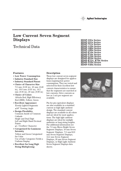
Features• Low Power Consumption • Industry Standard Size• Industry Standard Pinout • Choice of Character Size7.6 mm (0.30 in), 10 mm (0.40 in), 10.9 mm (0.43 in), 14.2 mm (0.56 in), 20 mm (0.80 in)• Choice of ColorsAlGaAs Red, High Efficiency Red (HER), Yellow, Green• Excellent Appearance Evenly Lighted Segments±50° Viewing Angle• Design FlexibilityCommon Anode or Common CathodeSingle and Dual DigitLeft and Right Hand Decimal Points±1. Overflow Character• Categorized for Luminous IntensityYellow and Green Categorized for ColorUse of Like Categories Yields a Uniform Display• Excellent for Long Digit String Multiplexing DescriptionThese low current seven segment displays are designed for applica-tions requiring low power consumption. They are tested and selected for their excellent low current characteristics to ensure that the segments are matched at low currents. Drive currents as low as 1 mA per segment are available.Pin for pin equivalent displays are also available in a standard current or high light ambient design. The standard current displays are available in all colors and are ideal for most applica-tions. The high light ambient displays are ideal for sunlight ambients or long string lengths. For additional information see the 7.6 mm Micro Bright Seven Segment Displays, 10 mm Seven Segment Displays, 7.6 mm/10.9 mm Seven Segment Displays, 14.2 mm Seven Segment Displays, 20 mm Seven Segment Displays, or High Light Ambient Seven Segment Displays data sheets.Low Current Seven SegmentDisplays Technical Data HDSP-335x SeriesHDSP-555x SeriesHDSP-751x SeriesHDSP-A10x Series HDSP-A80x Series HDSP-A90x Series HDSP-E10x Series HDSP-F10x Series HDSP-G10x Series HDSP-H10x Series HDSP-K12x, K70x Series HDSP-N10x SeriesHDSP-N40x SeriesDevicesAlGaAs HER Yellow Green Package HDSP-HDSP-HDSP-HDSP-Description Drawing A1017511A801A9017.6 mm Common Anode Right Hand Decimal A A1037513A803A9037.6 mm Common Cathode Right Hand Decimal B A1077517A807A9077.6 mm Common Anode ±1. Overflow C A1087518A808A9087.6 mm Common Cathode ±1. Overflow D F10110 mm Common Anode Right Hand Decimal E F10310 mm Common Cathode Right Hand Decimal F F10710 mm Common Anode ±1. Overflow G F10810 mm Common Cathode ±1. Overflow H G10110 mm Two Digit Common Anode Right Hand Decimal X G10310 mm Two Digit Common Cathode Right Hand Decimal Y E100335010.9 mm Common Anode Left Hand Decimal I E101335110.9 mm Common Anode Right Hand Decimal J E103335310.9 mm Common Cathode Right Hand Decimal K E106335610.9 mm Universal ±1. Overflow[1]L H101555114.2 mm Common Anode Right Hand Decimal M H103555314.2 mm Common Cathode Right Hand Decimal N H107555714.2 mm Common Anode ±1. Overflow O H108555814.2 mm Common Cathode ±1. Overflow P K121K70114.2 mm Two Digit Common Anode Right Hand Decimal R K123K70314.2 mm Two Digit Common Cathode Right Hand Decimal S N10020 mm Common Anode Left Hand Decimal Q N101N40120 mm Common Anode Right Hand Decimal T N103N40320 mm Common Cathode Right Hand Decimal U N10520 mm Common Cathode Left Hand Decimal V N106N40620 mm Universal ±1. Overflow[1]W Note:1. Universal pinout brings the anode and cathode of each segment’s LED out to separate pins. See internal diagrams L or W.Part Numbering System5082-x xx x-x x x xxHDSP-x xx x-x x x xxMechanical Options[1]00: No mechanical optionColor Bin Options[1,2]0: No color bin limitationMaximum Intensity Bin[1,2]0: No maximum intensity bin limitationMinimum Intensity Bin[1,2]0: No minimum intensity bin limitationDevice Configuration/Color[1]G: GreenDevice Specific Configuration[1]Refer to respective datasheetPackage[1]Refer to Respective datasheetNotes:1. For codes not listed in the figure above, please refer to the respective datasheet or contact your nearest Agilent representative fordetails.2. Bin options refer to shippable bins for a part-number. Color and Intensity Bins are typically restricted to 1 bin per tube (excep-tions may apply). Please refer to respective datasheet for specific bin limit information.Package DimensionsPackage Dimensions (cont.)Package Dimensions (cont.)*The Side View of package indicates Country of Origin.Package Dimensions (cont.)Package Dimensions (cont.)Package Dimensions (cont.)Internal Circuit DiagramInternal Circuit Diagram (cont.)Absolute Maximum RatingsAlGaAs Red - HDSP-HERA10X/E10X/H10X HDSP-751X/Yellow GreenK12X/N10X/N40X335X/555X/HDSP-A80X HDSP-A90X Description F10X, G10X Series K70X Series Series Series Units Average Power per Segment or DP375264mW Peak Forward Current per 45mA Segment or DPDC Forward Current per15[1]15[2]mA Segment or DPOperating Temperature Range-20 to +100-40 to +100°C Storage Temperature Range -55 to +100°C Reverse Voltage per Segment 3.0V or DPWave Soldering Temperature for 3Seconds (1.60 mm [0.063 in.] below 250°C seating body)Notes:1. Derate above 91°C at 0.53 mA/°C.2. Derate HER/Yellow above 80°C at 0.38 mA/°C and Green above 71°C at 0.31 mA/°C.Electrical/Optical Characteristics at T A = 25°CAlGaAs RedDeviceSeriesHDSP-Parameter Symbol Min.Typ.Max.Units Test Conditions315600I F = 1 mA A10x3600I F = 5 mA330650I F = 1 mAF10x, G10x3900I F = 5 mA390650I F = 1 mA E10x Luminous Intensity/Segment[1,2]I Vµcd(Digit Average)3900I F = 5 mA400700I F = 1 mAH10x, K12x4200I F = 5 mA270590I F = 1 mAN10x, N40x3500I F = 5 mA1.6I F = 1 mAForward Voltage/Segment or DP V F 1.7V I F = 5 mA1.82.2I F = 20 mA PkAll Devices Peak WavelengthλPEAK645nmDominant Wavelength[3]λd637nmReverse Voltage/Segment or DP[4]V R 3.015V I R = 100 µATemperature Coefficient of∆V F/°C-2 mV mV/°CV F/Segment or DPA10x255F10x, G10x320E10x340Thermal Resistance LED RθJ-PIN°C/W/SegH10x, K12x Junction-to-Pin400N10x, N40x430High Efficiency RedDeviceSeriesHDSP-Parameter Symbol Min.Typ.Max.Units Test Conditions160270I F = 2 mA 751x1050I F = 5 mA200300I F = 2 mA Luminous Intensity/Segment[1,2]I V mcd(Digit Average)1200I F = 5 mA335x, 555x,K70x270370I F = 2 mA1480I F = 5 mA1.6I F = 2 mAForward Voltage/Segment or DP V F 1.7V I F = 5 mA2.1 2.5I F = 20 mA Pk All Devices Peak WavelengthλPEAK635nmDominant Wavelength[3]λd626nmReverse Voltage/Segment or DP[4]V R 3.030V I R = 100 µATemperature Coefficient of∆V F/°C-2mV/°CV F/Segment or DP751x200335x Thermal Resistance LED RθJ-PIN280°C/WJunction-to-Pin555x, K70x345YellowDeviceSeriesHDSP-Parameter Symbol Min.Typ.Max.Units Test Conditions Luminous Intensity/Segment[1,2]250420I F = 4 mA(Digit Average)I V mcd1300I F = 10 mA1.7I F = 4 mAForward Voltage/Segment or DP V F 1.8V I F = 5 mA A80x2.1 2.5I F = 20 mA PkPeak WavelengthλPEAK583nmDominant Wavelength[3,5]λd581.5585592.5nmReverse Voltage/Segment or DP[4]V R 3.030V I R = 100 µATemperature Coefficient of∆V F/°C-2mV/°CV F/Segment or DPThermal Resistance LED RθJ-PIN200°C/WJunction-to-PinGreenDeviceSeriesHDSP-Parameter Symbol Min.Typ.Max.Units Test Conditions Luminous Intensity/Segment[1,2]250475I F = 4 mA(Digit Average)I V mcd1500I F = 10 mA1.9I F = 4 mAForward Voltage/Segment or DP V F 2.0V I F = 10 mA A90x2.1 2.5I F = 20 mA PkPeak WavelengthλPEAK566nmDominant Wavelength[3,5]λd571577nmReverse Voltage/Segment or DP[4]V R 3.030V I R = 100 µATemperature Coefficient of∆V F/°C-2mV/°CV F/Segment or DPThermal Resistance LED RθJ-PIN200°C/WJunction-to-PinNotes:1. Device case temperature is 25°C prior to the intensity measurement.2. The digits are categorized for luminous intensity. The intensity category is designated by a letter on the side of the package.3. The dominant wavelength, λd, is derived from the CIE chromaticity diagram and is the single wavelength which defines the color of thedevice.4. Typical specification for reference only. Do not exceed absolute maximum ratings.5. The yellow (HDSP-A800) and Green (HDSP-A900) displays are categorized for dominant wavelength. The category is designated by anumber adjacent to the luminous intensity category letter.AlGaAs RedIntensity Bin Limits (mcd)AlGaAs RedHDSP-A10xIV Bin Category Min.Max.E0.3150.520F0.4280.759G0.621 1.16H0.945 1.71I 1.40 2.56J 2.10 3.84K 3.14 5.75L 4.708.55HDSP-E10x/F10x/G10xIV Bin Category Min.Max.D0.3910.650E0.5320.923F0.755 1.39G 1.13 2.08H 1.70 3.14HDSP-H10x/K12xIV Bin Category Min.Max.C0.4150.690D0.5650.990E0.810 1.50F 1.20 2.20G 1.80 3.30H 2.73 5.00I 4.097.50HDSP-N10xIV Bin Category Min.Max.A0.2700.400B0.3250.500C0.4150.690D0.5650.990E0.810 1.50F 1.20 2.20G 1.80 3.30H 2.73 5.00I 4.097.50Intensity Bin Limits (mcd), continued HERHDSP-751xIV Bin Category Min.Max.B0.1600.240C0.2000.300D0.2500.385E0.3150.520F0.4280.759G0.621 1.16HDSP-751xIV Bin Category Min.Max.B0.2400.366C0.3000.477D0.3910.650E0.5320.923F0.755 1.39G 1.13 2.08H 1.70 3.14HDSP-555x/K70xIV Bin Category Min.Max.A0.2700.400B0.3250.500C0.4150.690D0.5650.990E0.810 1.50F 1.20 2.20G 1.80 3.30H 2.73 5.00I 4.097.50Intensity Bin Limits (mcd), continued YellowHDSP-A80xIV Bin Category Min.Max.D0.2500.385E0.3150.520F0.4250.760G0.625 1.14H0.940 1.70I 1.40 2.56J 2.10 3.84K 3.14 5.76L 4.718.64M7.0713.00N10.6019.40O15.9029.20P23.9043.80Q35.8065.60GreenHDSP-A90xIV Bin Category Min.Max.E0.3150.520F0.4250.760G0.625 1.14H0.940 1.70I 1.40 2.56J 2.10 3.84K 3.14 5.76L 4.718.64M7.0713.00N10.6019.40O15.9029.20P23.9043.80Q35.8065.60Electrical/OpticalFor more information on electrical/optical characteristics, please see Application Note 1005.Contrast Enhancement For information on contrast enhancement, please see Application Note 1015.Soldering/Cleaning Cleaning agents from the ketone family (acetone, methyl ethyl ketone, etc.) and from the chorinated hydrocarbon family (methylene chloride, trichloro-ethylene, carbon tetrachloride, etc.) are not recommended for cleaning LED parts. All of these various solvents attack or dissolve the encapsulating epoxies used to form the package of plastic LED parts.For information on soldering LEDs, please refer to Application Note 1027.Note:All categories are established for classification of products. Productsmay not be available in all categories. Please contact your localAgilent representatives for further clarification/information.Color Categories/semiconductorsFor product information and a complete list ofdistributors, please go to our web site.For technical assistance call:Americas/Canada: +1 (800) 235-0312 or(916) 788 6763Europe: +49 (0) 6441 92460China: 10800 650 0017Hong Kong: (+65) 6271 2451India, Australia, New Zealand: (+65) 6271 2394Japan: (+81 3) 3335-8152(Domestic/International), or0120-61-1280(Domestic Only)Korea: (+65) 6271 2194Malaysia, Singapore: (+65) 6271 2054Taiwan: (+65) 6271 2654Data subject to change.Copyright © 2005 Agilent Technologies, Inc.Obsoletes 5988-8412ENJanuary 19, 20055989-0080EN。
HK-508型铁含量分析仪说明书
京制 01080126 号HK-508型铁含量分析仪使用说明书产品版本:1.0 北京华科仪电力仪表研究所目录一、概述1.1 仪器简介 (1)1.2 显示及操作面板 (1)1.3 工作原理 (2)二、技术指标 (4)三、试剂的制备3.1 显色试剂的制备 (5)3.2 标准储备溶液 (5)四、编程4.1 开机 (6)4.2 程序单元 (6)4.2.1 主菜单 (6)4.2.2 空白校准菜单 (7)4.2.3 曲线校准菜单 (8)4.2.4 参数设置菜单 (9)4.2.5 历史数据菜单 (10)五、仪器的使用5.1 使用条件 (12)5.2 仪器的安装方法 (12)5.3 仪器的校准 (12)5.3.1 曲线校准 (12)5.3.2 空白校准 (15)5.4 水样的测定方法 (15)5.4.1 待测水样的显色 (15)5.4.2 水样的测量 (15)5.5 注意事项 (15)六、仪器的成套性 (17)1一 概述仪器外型为一个密封的金属壳体,坚固防水;显示屏为大屏幕的点阵液晶,中文菜单,易于理 解,操作方便;测量数据为直读式,并可根据需要保存测量值。
其中,键盘功能如下::垂直或水平循环移动光标,选择所需的菜单或参数。
:当参数选定后,可增加参数的数值; 当显示历史数据、对历史数据进行查询时,按此键可显示上页数据。
:当参数选定后,可减小参数的数值。
当显示历史数据、对历史数据进行查询时,按此键可显示下页数据。
:当选定所需的菜单或功能项,按此键可进入该菜单或功能项;:返回上一菜单或上一页。
:排空比色池中的液体,此时测量值不存储。
排液时间设置为 16 秒。
:对测量数值进行存储,同时排空比色池中的液体。
1. 测量数值的存储:仪器具有 6 个存储通道,可将不同水样的测量值存储到所需的通道中。
在测量画面中, 待测量水样的数值显示稳定后,直接用“+”或“-”键改变所需存储的通道,然后按下“存 储”键。
2. 空白校准或曲线校准的存储:空白和曲线校准的时间将直接存储到 6 个通道中,而无需选择存储通道,(这样做的目的 在于可随时了解仪器的校准情况)。
深圳亚特尔 M60-2M 电机保护器 中文说明书

用户手册
深圳市亚特尔科技有限公司
M60-2M 用户手册 V2.02
目
录
前 言 ........................................................................................................................................................2
十五、 附表一:主机显示字符与故障类型对照表.......................................................................32
十六、 附表二:增安型电机 TE 时间保护特性表 .......................................................................33
六、 AD23 操作面板及使用说Байду номын сангаас..........................................................................................................4
1. 功能 ................................................................................................................................................5 2. 菜单结构 ........................................................................................................................................5 3. 菜单含义 ........................................................................................................................................6 4. 运行监控 ........................................................................................................................................6 5. 参数查看 ........................................................................................................................................6 6. 参数设定 ........................................................................................................................................6 7. 参数设定范围 ................................................................................................................................7 8. 功能设置说明 ................................................................................................................................8 9. 记录查看 ......................................................................................................................................11
MSK5230-1.9中文资料

In voltage regulator applications where very large load currents are present, the load connection is very important. The path connecting the output of the regulator to the load must be extremely low impedance to avoid affecting the load regulation specifications. Any impedance in this path will form a voltage divider with the load.
MINIMIZING POWER DISSIPATION:
Many applications can not take full advantage of the extremely low dropout specifications of the regulator due to large input to output voltage differences. The simple circuit below illustrates a method to reduce the input voltage at the regulator to just over the dropout specification to keep the internal power dissipation minimized:
1
PIN-OUT INFORMATION
1 VIN 2 VOUT 3 Ground
KBY50-10说明书(1)

油泵支架 齿轮泵 CBTW-Fc50
油泵出油口接头 三通弯头 压力表开关接头 K70-0-04 溢流阀接头
溢流阀 YF-L20C
换向机构 K70-3
油泵进油口接头 K70-0-03
前轮支架 K70-5-0
压力表油管
油缸及注浆缸 K70-1
二位四通换向阀 24SO-L20H-W
附图1 KBY50/10-11注浆泵
名称
4
1#
1 丁腈橡胶(NBR)
1 HT200 2 聚氨酯橡胶(UR)
1 无缝钢管/45 2 丁腈橡胶(NBR)
1 45 2 丁腈橡胶(NBR) 1 ZG45
1 黄铜
1 45
数量
材料
16 K70-1-0008
15 K70-1-0009
14 GB/T70.1-2000
该系列注浆泵分风冷和水冷两种,用户可根据需要选 择。 2、 主要技术参数(见表)
型号 KBY50/10-11
公称流量 L/min
50
公称压力 MPa
额定 往复次数 min-1
容积 效率
%
总效率 %
外形尺寸 mm
卡夫特 K-703 室温硫化硅橡胶 技术说明书

广东恒大新材料科技有限公司 地 址: 广东省惠州市龙丰都田工业区 电 话*************传 真*************网 址: Data Sheet 技术说明书卡夫特 K-703Jan. 2010. 更新卡夫特K-703室温硫化硅橡胶1、性能特点本品是一种中性单组分室温固化硅橡胶,常溫下吸收空气中的水份固化,无毒、无污染、无腐蚀。
具有良好的电绝缘和抗电弧性能,粘接范围广、耐冷水性能优异、性能稳定、使用方便等特点,可在-60℃~200℃温度范围内长期使用。
本品有良好的粘附性,除常见的金属和非金属材料外,对金、银、不锈钢等难粘材料也具有一定的粘合力。
2、用途本品具有良好的粘合性和耐冷水性,用于粘接、密封、绝缘、防潮、防震材料,广泛应用于电子元件、半导体材料、电子电器等设备的粘接、密封,电加热器、电子仪表的防水、密封及电子元件的灌封等。
具体如用于各种水下仪器仪表防潮密封、海底电缆灌封、小型电机磁瓦粘结、高压包、传感器灌封前表涂、汽车底盘、冷冻冷藏设备的密封等,广泛应用于电热水器、冷冻柜、电冰箱、咖啡壶、豆浆机、电子元件等。
3、技术性能4、使用方法先将元器件做一般性清洁处理、干燥后,将本品从金属软管中挤出施胶,胶料接触空气中的水份,即由表及里固化。
5、注意事项①对于耐温元器件,可先在室温固化后,再在50~100℃,潮湿烘箱中处理4~8小时,赶掉低分子物,充分固化,以保证胶的性能。
②本产品在使用后,应将胶管盖紧,可保存再次使用。
6、包装规格: 45克/支 100克/支 300ml/支7、贮存: 本产品应贮存于阴凉干燥环境中,25℃以下贮存期为一年。
说明:以上数据是依据我们广泛实验所得,结果是可靠的。
但由于实际应用的多样性,应用条件不是我们所能控制,所以用户在使用前需进行试验以确认本品是否适用。
我公司不担保特定条件下使用我公司产品出现的问题,不承担任何直接、间接或意外损失的责任。
用户在使用过程中遇到什么问题,可以和我公司技术服务部联系,我们将竭力为您提供尽可能的帮助。
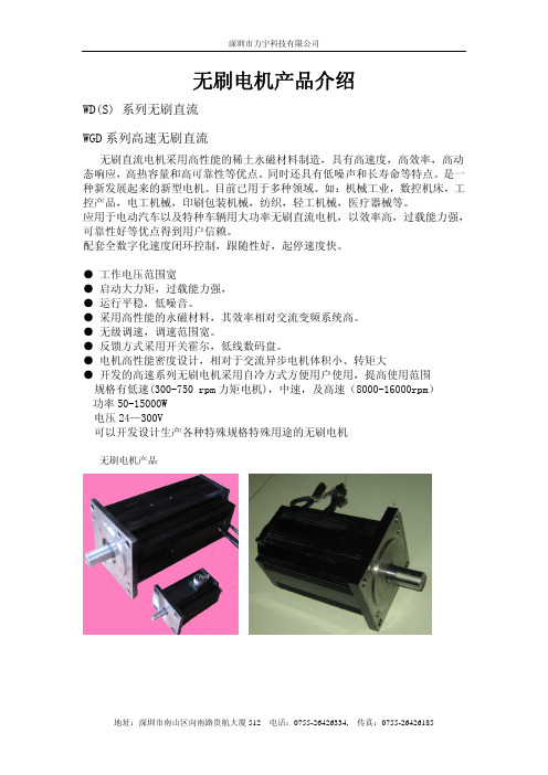
20101206无刷电机参数表
1.2
1.2
5.7
3.8
100-300
100-300
2
2
17
11.5
2000
3000
增量式 1000 增量式 1000 线,
线,增量式 增量式 2500 线,
2500 线,增量 增量式 3600 线。
式 3600 线。
MCBPLUS200-5/ MCBPLUS200-
10-
5/10-
1.5 7.2 100-300 2 21 2000 增量式 1000 线,增量式 2500 线,增量 式 3600 线。 MCBPLUS2008/16-
编码器反馈可选类 型
配套伺服驱动器
100WD-01
100WD-02
100WD03
100WD-04
100WD-05
100WD-06
0.5 2.4 72-100 3 7.5 2000 增量式 1000 线,增量式 2500 线,增量 式 3600 线。 BH0S1010
0.5 1.6 72-100 3 5 3000 增量式 1000 线,增量式 2500 线,增量 式 3600 线。 BH0S1010
110WDS-02
110WDS03
110WDS-04 110WDS-05 110WDS-06
1 4.8 100-300 2 14 2000 增量式 1000 线,增量式 2500 线,增量 式 3600 线。 MCBPLUS200-5 /10-
1 3.2 100-300 2 9.5 3000 增量式 1000 线,增量式 2500 线,增量 式 3600 线。 MCBPLUS2005/10-
60WGD-03
60WGD-04
60WGD-05
英飞凌 DD800S45KL3_B5 高绝缘等级模块 数据表
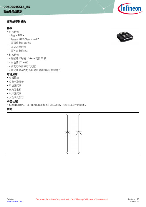
高绝缘等级模块特性•电气特性-V CES = 4500 V-I C nom = 800 A / I CRM = 1600 A -高直流电压稳定性-高动态稳定性-高冲击电流能力•机械特性-加强绝缘封装,10.4kV 交流 60 秒-封装的 CTI > 600-高爬电距离和电气间隙-碳化硅铝 (AlSiC) 基板提供更高的温度循环能力可选应用•电机传动•多电平逆变器•牵引变流器•风力发电机•中压变流器•大功率变流器产品认证•根据 IEC 60747、60749 和 60068标准的相关测试,符合工业应用的要求。
描述DD800S45KL3_B5高绝缘等级模块内容描述 . . . . . . . . . . . . . . . . . . . . . . . . . . . . . . . . . . . . . . . . . . . . . . . . . . . . . . . . . . . . . . . . . . . . . . . . . . . . . . . . . . . . . . . . .1特性 . . . . . . . . . . . . . . . . . . . . . . . . . . . . . . . . . . . . . . . . . . . . . . . . . . . . . . . . . . . . . . . . . . . . . . . . . . . . . . . . . . . . . . . . .1可选应用 . . . . . . . . . . . . . . . . . . . . . . . . . . . . . . . . . . . . . . . . . . . . . . . . . . . . . . . . . . . . . . . . . . . . . . . . . . . . . . . . . . . .1产品认证 . . . . . . . . . . . . . . . . . . . . . . . . . . . . . . . . . . . . . . . . . . . . . . . . . . . . . . . . . . . . . . . . . . . . . . . . . . . . . . . . . . . .1内容 . . . . . . . . . . . . . . . . . . . . . . . . . . . . . . . . . . . . . . . . . . . . . . . . . . . . . . . . . . . . . . . . . . . . . . . . . . . . . . . . . . . . . . . . .2 1封装 . . . . . . . . . . . . . . . . . . . . . . . . . . . . . . . . . . . . . . . . . . . . . . . . . . . . . . . . . . . . . . . . . . . . . . . . . . . . . . . . . . . . . . . . .3 2二极管,逆变器 . . . . . . . . . . . . . . . . . . . . . . . . . . . . . . . . . . . . . . . . . . . . . . . . . . . . . . . . . . . . . . . . . . . . . . . . . . . . . . .3 3特征参数图表 . . . . . . . . . . . . . . . . . . . . . . . . . . . . . . . . . . . . . . . . . . . . . . . . . . . . . . . . . . . . . . . . . . . . . . . . . . . . . . . .5 4电路拓扑图 . . . . . . . . . . . . . . . . . . . . . . . . . . . . . . . . . . . . . . . . . . . . . . . . . . . . . . . . . . . . . . . . . . . . . . . . . . . . . . . . . .7 5封装尺寸 . . . . . . . . . . . . . . . . . . . . . . . . . . . . . . . . . . . . . . . . . . . . . . . . . . . . . . . . . . . . . . . . . . . . . . . . . . . . . . . . . . . .8 6模块标签代码 . . . . . . . . . . . . . . . . . . . . . . . . . . . . . . . . . . . . . . . . . . . . . . . . . . . . . . . . . . . . . . . . . . . . . . . . . . . . . . . .9修订历史 . . . . . . . . . . . . . . . . . . . . . . . . . . . . . . . . . . . . . . . . . . . . . . . . . . . . . . . . . . . . . . . . . . . . . . . . . . . . . . . . . . .10免责声明 . . . . . . . . . . . . . . . . . . . . . . . . . . . . . . . . . . . . . . . . . . . . . . . . . . . . . . . . . . . . . . . . . . . . . . . . . . . . . . . . . . .111封装表 1绝缘参数特征参数代号标注或测试条件数值单位绝缘测试电压V ISOL RMS, f = 50 Hz, t = 60 s10.4kV 局部放电熄弧电压V isol RMS, f = 50 Hz, Q PD typ. 10 pC 3.5kV DC 稳定性V CE(D)T vj=25°C, 100 Fit3000V 模块基板材料AlSiC内部绝缘基本绝缘 (class 1, IEC 61140)AlN爬电距离d Creep端子至散热器64.0mm 爬电距离d Creep端子至端子56.0mm 电气间隙d Clear端子至散热器40.0mm 电气间隙d Clear端子至端子26.0mm 相对电痕指数CTI > 600表 2特征值特征参数代号标注或测试条件数值单位最小值典型值最大值杂散电感,模块L sCE25nH 模块引线电阻,端子-芯片R AA'+CC'T C=25°C, 每个开关0.51mΩ储存温度T stg-55125°CM6, 螺丝 4.25 5.75Nm 模块安装的安装扭距M根据相应的应用手册进行安装M8, 螺丝810Nm 端子安装扭矩M根据相应的应用手册进行安装重量G1000g 注:Dynamic Data valid in conjunction with FZ800R45KL3_B5 module2二极管,逆变器表 3最大标定值特征参数代号标注或测试条件数值单位反向重复峰值电压V RRM T vj = -40 °C4500VT vj = 25 °C4500T vj = 125 °C4500连续正向直流电流I F800A (待续)表 3(续) 最大标定值特征参数代号标注或测试条件数值单位正向重复峰值电流I FRM t P = 1 ms1600A I2t-值I2t t P = 10 ms, V R = 0 V T vj = 125 °C255kA²s 最大损耗功率P RQM T vj = 125 °C1600kW 最小开通时间t onmin10µs表 4特征值特征参数代号标注或测试条件数值单位最小值典型值最大值正向电压V F I F = 800 A, V GE = 0 V T vj = 25 °C 2.50 3.10VT vj = 125 °C 2.50 3.00反向恢复峰值电流I RM V R = 2800 V, I F = 800 A,V GE = -15 V, -di F/dt =3300 A/µs (T vj = 125 °C)T vj = 25 °C1000A T vj = 125 °C1150恢复电荷Q r V R = 2800 V, I F = 800 A,V GE = -15 V, -di F/dt =3300 A/µs (T vj = 125 °C)T vj = 25 °C770µC T vj = 125 °C1400反向恢复损耗(每脉冲)E rec V R = 2800 V, I F = 800 A,V GE = -15 V, -di F/dt =3300 A/µs (T vj = 125 °C)T vj = 25 °C1200mJ T vj = 125 °C2400结-外壳热阻R thJC每个二极管25.5K/kW 外壳-散热器热阻R thCH每个二极管, λgrease= 1 W/(m*K)21.0K/kW 允许开关的温度范围T vj op-50125°C4电路拓扑图图 15封装尺寸图 26 模块标签代码6模块标签代码图 3修订历史修订历史修订版本发布日期变更说明V1.02014-06-23Target datasheetV3.02016-05-31Final datasheetV3.12018-01-15Final datasheetn/a2020-09-01Datasheet migrated to a new system with a new layout and new revisionnumber schema: target or preliminary datasheet = 0.xy; final datasheet =1.xy1.102022-04-04Final datasheet商标所有参照产品或服务名称和商标均为其各自所有者的财产。
5k电位器
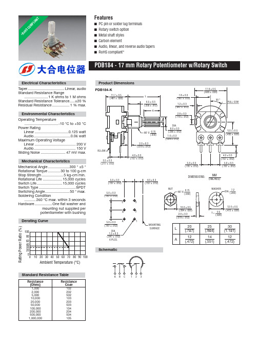
17.0 ± 0.5 (.669 ± .020)
30 °
FULL CCW
M7 X 0.75 (.030)
2.0 ± 0.3 (.079 ± .012)
6.0 ± 0.3 (.236 ± .012)
1.0 ± 0.3 (.039 ± .012)
Байду номын сангаас
R2 3.0 ± 0.3
(.118 ± .012)
6.0 ± 0.3 (.236 ± .012)
A
7.8 ± 0.3 (.307 ± .012)
1.2 ± 0.3 (.047 ± .012)
2.8 ± 0.3 (.110 ± .012)
17.0 ± 0.5 (.669 ± .020)
30 °
FULL CCW
R2=SW
5.5 ± 0.3 (.217 ± .012)
M7 X 0.75 (.030)
100 80 60 40 33 20 0
0 10 20 30 40 50 60 70 80 90 100
Ambient Temperature (°C)
Product Dimensions
PDB184-K
11.7 ± 0.5 (.461 ± .020)
L
6.5 ± 0.3 (.256 ± .012)
NUT
5.5 ± 0.3 (.217 ± .012) 5.0 ± 0.3 (.197 ± .012)
C
T = 0.5 (.020)
WASHER
12.0 ± 0.3 (.472 ± .012)
3.6 ± 0.3 (.142 ± .012)
2.5 ± 0.3 (.098 ± .012)
DIMENSIONS:
BA00JC5WT中文资料
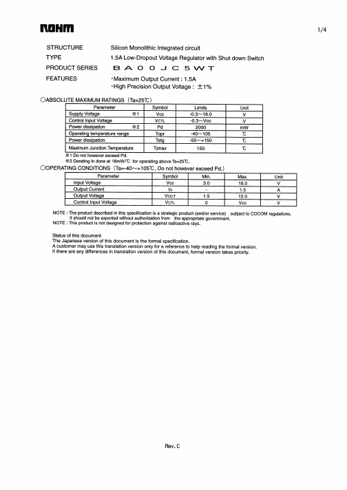
TEL : +33(0)1 56 97 30 60 FAX : +33(0) 1 56 97 30 80 TEL : +852(2)740-6262 TEL : +86(21)6279-2727 TEL : +86(411)8230-8549 TEL : +86(10)8525-2483 TEL : +866(2)2500-6956 TEL : +82(2)8182-700 TEL : +65-6332-2322 TEL : +60(3)7958-8355 TEL : +63(2)807-6872 TEL : +66(2)254-4890 FAX : +852(2)375-8971 FAX : +86(21)6247-2066 FAX : +86(411)8230-8537 FAX : +86(10)8525-2489 FAX : +866(2)2503-2869 FAX : +82(2)8182-715 FAX : +65-6332-5662 FAX : +60(3)7958-8377 FAX : +63(2)809-1422 FAX : +66(2)256-6334
Appendix
Notes
No technical content pages of this document may be reproduced in any form or transmitted by any means without prior permission of ROHM CO.,LTD. The contents described herein are subject to change without notice. The specifications for the product described in this document are for reference only. Upon actual use, therefore, please request that specifications to be separately delivered. Application circuit diagrams and circuit constants contained herein are shown as examples of standard use and operation. Please pay careful attention to the peripheral conditions when designing circuits and deciding upon circuit constants in the set. Any data, including, but not limited to application circuit diagrams information, described herein are intended only as illustrations of such devices and not as the specifications for such devices. ROHM CO.,LTD. disclaims any warranty that any use of such devices shall be free from infringement of any third party's intellectual property rights or other proprietary rights, and further, assumes no liability of whatsoever nature in the event of any such infringement, or arising from or connected with or related to the use of such devices. Upon the sale of any such devices, other than for buyer's right to use such devices itself, resell or otherwise dispose of the same, no express or implied right or license to practice or commercially exploit any intellectual property rights or other proprietary rights owned or controlled by ROHM CO., LTD. is granted to any such buyer. Products listed in this document are no antiradiation design.
MSK5232-3.3TS中文资料

The output voltage ripple of the MSK 5232 series voltage regulators can be minimized by placing a filter capacitor from the output to ground. The optimum value for this capacitor may vary from one application to the next, but a minimum of 20µF is recommended for optimum performance. Transient load response can also be improved by placing a capacitor directly across the load. The capacitor should not be an ultra-low ESR type. Tantalum capacitors are best for fast load transients but aluminum electrolytics will work fine in most applications.
(10 Seconds Soldering) TJ Operating Temperature
MSK 5232 Series . . . . . . . . . -40°C to +85°C MSK 5232H/E Series . . . . . . . -55°C to +125°C
ELECTRICAL SPECIFICATIONS
元器件交易网
ISO-9001 CERTIFIED BY DSCC
- 1、下载文档前请自行甄别文档内容的完整性,平台不提供额外的编辑、内容补充、找答案等附加服务。
- 2、"仅部分预览"的文档,不可在线预览部分如存在完整性等问题,可反馈申请退款(可完整预览的文档不适用该条件!)。
- 3、如文档侵犯您的权益,请联系客服反馈,我们会尽快为您处理(人工客服工作时间:9:00-18:30)。
Features• Low Power Consumption • Industry Standard Size• Industry Standard Pinout • Choice of Character Size7.6 mm (0.30 in), 10 mm (0.40 in), 10.9 mm (0.43 in), 14.2 mm (0.56 in), 20 mm (0.80 in)• Choice of ColorsAlGaAs Red, High Efficiency Red (HER), Yellow, Green• Excellent Appearance Evenly Lighted Segments±50° Viewing Angle• Design FlexibilityCommon Anode or Common CathodeSingle and Dual DigitLeft and Right Hand Decimal Points±1. Overflow Character• Categorized for Luminous IntensityYellow and Green Categorized for ColorUse of Like Categories Yields a Uniform Display• Excellent for Long Digit String Multiplexing DescriptionThese low current seven segment displays are designed for applica-tions requiring low power consumption. They are tested and selected for their excellent low current characteristics to ensure that the segments are matched at low currents. Drive currents as low as 1 mA per segment are available.Pin for pin equivalent displays are also available in a standard current or high light ambient design. The standard current displays are available in all colors and are ideal for most applica-tions. The high light ambient displays are ideal for sunlight ambients or long string lengths. For additional information see the 7.6 mm Micro Bright Seven Segment Displays, 10 mm Seven Segment Displays, 7.6 mm/10.9 mm Seven Segment Displays, 14.2 mm Seven Segment Displays, 20 mm Seven Segment Displays, or High Light Ambient Seven Segment Displays data sheets.Low Current Seven SegmentDisplays Technical Data HDSP-335x SeriesHDSP-555x SeriesHDSP-751x SeriesHDSP-A10x Series HDSP-A80x Series HDSP-A90x Series HDSP-E10x Series HDSP-F10x Series HDSP-G10x Series HDSP-H10x Series HDSP-K12x, K70x Series HDSP-N10x SeriesHDSP-N40x SeriesDevicesAlGaAs HER Yellow Green Package HDSP-HDSP-HDSP-HDSP-Description Drawing A1017511A801A9017.6 mm Common Anode Right Hand Decimal A A1037513A803A9037.6 mm Common Cathode Right Hand Decimal B A1077517A807A9077.6 mm Common Anode ±1. Overflow C A1087518A808A9087.6 mm Common Cathode ±1. Overflow D F10110 mm Common Anode Right Hand Decimal E F10310 mm Common Cathode Right Hand Decimal F F10710 mm Common Anode ±1. Overflow G F10810 mm Common Cathode ±1. Overflow H G10110 mm Two Digit Common Anode Right Hand Decimal X G10310 mm Two Digit Common Cathode Right Hand Decimal Y E100335010.9 mm Common Anode Left Hand Decimal I E101335110.9 mm Common Anode Right Hand Decimal J E103335310.9 mm Common Cathode Right Hand Decimal K E106335610.9 mm Universal ±1. Overflow[1]L H101555114.2 mm Common Anode Right Hand Decimal M H103555314.2 mm Common Cathode Right Hand Decimal N H107555714.2 mm Common Anode ±1. Overflow O H108555814.2 mm Common Cathode ±1. Overflow P K121K70114.2 mm Two Digit Common Anode Right Hand Decimal R K123K70314.2 mm Two Digit Common Cathode Right Hand Decimal S N10020 mm Common Anode Left Hand Decimal Q N101N40120 mm Common Anode Right Hand Decimal T N103N40320 mm Common Cathode Right Hand Decimal U N10520 mm Common Cathode Left Hand Decimal V N106N40620 mm Universal ±1. Overflow[1]W Note:1. Universal pinout brings the anode and cathode of each segment’s LED out to separate pins. See internal diagrams L or W.Part Numbering System5082-x xx x-x x x xxHDSP-x xx x-x x x xxMechanical Options[1]00: No mechanical optionColor Bin Options[1,2]0: No color bin limitationMaximum Intensity Bin[1,2]0: No maximum intensity bin limitationMinimum Intensity Bin[1,2]0: No minimum intensity bin limitationDevice Configuration/Color[1]G: GreenDevice Specific Configuration[1]Refer to respective datasheetPackage[1]Refer to Respective datasheetNotes:1. For codes not listed in the figure above, please refer to the respective datasheet or contact your nearest Agilent representative fordetails.2. Bin options refer to shippable bins for a part-number. Color and Intensity Bins are typically restricted to 1 bin per tube (excep-tions may apply). Please refer to respective datasheet for specific bin limit information.Package DimensionsPackage Dimensions (cont.)Package Dimensions (cont.)*The Side View of package indicates Country of Origin.Package Dimensions (cont.)Package Dimensions (cont.)Package Dimensions (cont.)Internal Circuit DiagramInternal Circuit Diagram (cont.)Absolute Maximum RatingsAlGaAs Red - HDSP-HERA10X/E10X/H10X HDSP-751X/Yellow GreenK12X/N10X/N40X335X/555X/HDSP-A80X HDSP-A90X Description F10X, G10X Series K70X Series Series Series Units Average Power per Segment or DP375264mW Peak Forward Current per 45mA Segment or DPDC Forward Current per15[1]15[2]mA Segment or DPOperating Temperature Range-20 to +100-40 to +100°C Storage Temperature Range -55 to +100°C Reverse Voltage per Segment 3.0V or DPWave Soldering Temperature for 3Seconds (1.60 mm [0.063 in.] below 250°C seating body)Notes:1. Derate above 91°C at 0.53 mA/°C.2. Derate HER/Yellow above 80°C at 0.38 mA/°C and Green above 71°C at 0.31 mA/°C.Electrical/Optical Characteristics at T A = 25°CAlGaAs RedDeviceSeriesHDSP-Parameter Symbol Min.Typ.Max.Units Test Conditions315600I F = 1 mA A10x3600I F = 5 mA330650I F = 1 mAF10x, G10x3900I F = 5 mA390650I F = 1 mA E10x Luminous Intensity/Segment[1,2]I Vµcd(Digit Average)3900I F = 5 mA400700I F = 1 mAH10x, K12x4200I F = 5 mA270590I F = 1 mAN10x, N40x3500I F = 5 mA1.6I F = 1 mAForward Voltage/Segment or DP V F 1.7V I F = 5 mA1.82.2I F = 20 mA PkAll Devices Peak WavelengthλPEAK645nmDominant Wavelength[3]λd637nmReverse Voltage/Segment or DP[4]V R 3.015V I R = 100 µATemperature Coefficient of∆V F/°C-2 mV mV/°CV F/Segment or DPA10x255F10x, G10x320E10x340Thermal Resistance LED RθJ-PIN°C/W/SegH10x, K12x Junction-to-Pin400N10x, N40x430High Efficiency RedDeviceSeriesHDSP-Parameter Symbol Min.Typ.Max.Units Test Conditions160270I F = 2 mA 751x1050I F = 5 mA200300I F = 2 mA Luminous Intensity/Segment[1,2]I V mcd(Digit Average)1200I F = 5 mA335x, 555x,K70x270370I F = 2 mA1480I F = 5 mA1.6I F = 2 mAForward Voltage/Segment or DP V F 1.7V I F = 5 mA2.1 2.5I F = 20 mA Pk All Devices Peak WavelengthλPEAK635nmDominant Wavelength[3]λd626nmReverse Voltage/Segment or DP[4]V R 3.030V I R = 100 µATemperature Coefficient of∆V F/°C-2mV/°CV F/Segment or DP751x200335x Thermal Resistance LED RθJ-PIN280°C/WJunction-to-Pin555x, K70x345YellowDeviceSeriesHDSP-Parameter Symbol Min.Typ.Max.Units Test Conditions Luminous Intensity/Segment[1,2]250420I F = 4 mA(Digit Average)I V mcd1300I F = 10 mA1.7I F = 4 mAForward Voltage/Segment or DP V F 1.8V I F = 5 mA A80x2.1 2.5I F = 20 mA PkPeak WavelengthλPEAK583nmDominant Wavelength[3,5]λd581.5585592.5nmReverse Voltage/Segment or DP[4]V R 3.030V I R = 100 µATemperature Coefficient of∆V F/°C-2mV/°CV F/Segment or DPThermal Resistance LED RθJ-PIN200°C/WJunction-to-PinGreenDeviceSeriesHDSP-Parameter Symbol Min.Typ.Max.Units Test Conditions Luminous Intensity/Segment[1,2]250475I F = 4 mA(Digit Average)I V mcd1500I F = 10 mA1.9I F = 4 mAForward Voltage/Segment or DP V F 2.0V I F = 10 mA A90x2.1 2.5I F = 20 mA PkPeak WavelengthλPEAK566nmDominant Wavelength[3,5]λd571577nmReverse Voltage/Segment or DP[4]V R 3.030V I R = 100 µATemperature Coefficient of∆V F/°C-2mV/°CV F/Segment or DPThermal Resistance LED RθJ-PIN200°C/WJunction-to-PinNotes:1. Device case temperature is 25°C prior to the intensity measurement.2. The digits are categorized for luminous intensity. The intensity category is designated by a letter on the side of the package.3. The dominant wavelength, λd, is derived from the CIE chromaticity diagram and is the single wavelength which defines the color of thedevice.4. Typical specification for reference only. Do not exceed absolute maximum ratings.5. The yellow (HDSP-A800) and Green (HDSP-A900) displays are categorized for dominant wavelength. The category is designated by anumber adjacent to the luminous intensity category letter.Figure 1. Maximum AllowableAverage or DC Current vs. Ambient Temperature.Figure 2. Forward Current vs.Forward Voltage.AlGaAs RedFigure 4. Relative Efficiency (Luminous Intensity per UnitCurrent) vs. Peak Current.Figure 3. Relative Luminous Intensity vs. DC Forward Current.Figure 5. Maximum Allowable Average or DC Current vs. Ambient Temperature.Figure 6. Forward Current vs. Forward Voltage.HER, Yellow, GreenFigure 7. Relative Luminous Intensityvs. DC Forward Current.Figure 8. Relative Efficiency(Luminous Intensity per UnitCurrent) vs. Peak Current.Intensity Bin Limits (mcd)AlGaAs RedHDSP-A10xIV Bin Category Min.Max.E0.3150.520F0.4280.759G0.621 1.16H0.945 1.71I 1.40 2.56J 2.10 3.84K 3.14 5.75L 4.708.55HDSP-E10x/F10x/G10xIV Bin Category Min.Max.D0.3910.650E0.5320.923F0.755 1.39G 1.13 2.08H 1.70 3.14HDSP-H10x/K12xIV Bin Category Min.Max.C0.4150.690D0.5650.990E0.810 1.50F 1.20 2.20G 1.80 3.30H 2.73 5.00I 4.097.50HDSP-N10xIV Bin Category Min.Max.A0.2700.400B0.3250.500C0.4150.690D0.5650.990E0.810 1.50F 1.20 2.20G 1.80 3.30H 2.73 5.00I 4.097.50Intensity Bin Limits (mcd), continued HERHDSP-751xIV Bin Category Min.Max.B0.1600.240C0.2000.300D0.2500.385E0.3150.520F0.4280.759G0.621 1.16HDSP-751xIV Bin Category Min.Max.B0.2400.366C0.3000.477D0.3910.650E0.5320.923F0.755 1.39G 1.13 2.08H 1.70 3.14HDSP-555x/K70xIV Bin Category Min.Max.A0.2700.400B0.3250.500C0.4150.690D0.5650.990E0.810 1.50F 1.20 2.20G 1.80 3.30H 2.73 5.00I 4.097.50Intensity Bin Limits (mcd), continued YellowHDSP-A80xIV Bin Category Min.Max.D0.2500.385E0.3150.520F0.4250.760G0.625 1.14H0.940 1.70I 1.40 2.56J 2.10 3.84K 3.14 5.76L 4.718.64M7.0713.00N10.6019.40O15.9029.20P23.9043.80Q35.8065.60GreenHDSP-A90xIV Bin Category Min.Max.E0.3150.520F0.4250.760G0.625 1.14H0.940 1.70I 1.40 2.56J 2.10 3.84K 3.14 5.76L 4.718.64M7.0713.00N10.6019.40O15.9029.20P23.9043.80Q35.8065.60Electrical/OpticalFor more information on electrical/optical characteristics, please see Application Note 1005.Contrast Enhancement For information on contrast enhancement, please see Application Note 1015.Soldering/Cleaning Cleaning agents from the ketone family (acetone, methyl ethyl ketone, etc.) and from the chorinated hydrocarbon family (methylene chloride, trichloro-ethylene, carbon tetrachloride, etc.) are not recommended for cleaning LED parts. All of these various solvents attack or dissolve the encapsulating epoxies used to form the package of plastic LED parts.For information on soldering LEDs, please refer to Application Note 1027.Note:All categories are established for classification of products. Productsmay not be available in all categories. Please contact your localAgilent representatives for further clarification/information.Color Categories/semiconductorsFor product information and a complete list ofdistributors, please go to our web site.For technical assistance call:Americas/Canada: +1 (800) 235-0312 or(916) 788 6763Europe: +49 (0) 6441 92460China: 10800 650 0017Hong Kong: (+65) 6271 2451India, Australia, New Zealand: (+65) 6271 2394Japan: (+81 3) 3335-8152(Domestic/International), or0120-61-1280(Domestic Only)Korea: (+65) 6271 2194Malaysia, Singapore: (+65) 6271 2054Taiwan: (+65) 6271 2654Data subject to change.Copyright © 2005 Agilent Technologies, Inc.Obsoletes 5988-8412ENJanuary 19, 20055989-0080EN。
