新能源电动汽车英文翻译
新能源汽车专业英语1-1

1.1 The Development of Electric Vehicles
The early electric vehicles, such as the 1902 Wood's Phaeton (Figure 1.1), were little more than electrified horseless carriages. The Phaeton had a range of 18 miles, a top speed of 14 mph and cost $2,000.
疑难句子分析
*1 The decline of the electric vehicle was brought about by several major developments, such as a better system of roads in America By the 1920s, lower gasoline car price than electric cars due to the initiation of mass production of internal combustion engine vehicles by Henry Ford, the discovery of Texas crude oil and the invention of the electric starter in 1912 eliminating the need for the hand crank.
新能源汽车专业英语 第1章 新能源汽车概述
认真听讲,做好记录,大胆实践,可到实验室对照实物学习
参考教材
新能源汽车专业英语,宋进桂等编,机械工业出版社,2020
课程结构
THE STRUCTURE OF THE COURSE
基础知识 Overview Battery
Drive motor Transmission Case study
France and Great Britain were the first nations to support the widespread development of electric vehicles in the late 1800s. In 1899, a Belgian built electric racing car called "La Jamais Contente" set a world record for land speed - 68 mph.
新能源汽车专业英语
NEW ENERGY VEHICLE ENGLISH
授课人:
NEW ENERGY VEHICLE ENGLISH
Foreword
课程介绍
课程属性—— ****课 课时——36学时 课程内容——新能源汽车基础(结构原理)、诊断修理、汽车设 计制造
学习目的
1.打好基础:掌握必要的专业词汇,熟悉并巩固语法与专业知识, 开阔眼界, 2.掌握一定的翻译技能和基本阅读能力,能看懂较简单的英文专业 使用与维修资料,能提高使用诊断仪的能力和解决维修技术问题。
The years 1899 and 1900 were the high point of electric cars in America, as they outsold all other types of cars. While basic electric cars cost under $1,000, most early electric vehicles were ornate. They had fancy interiors, with expensive materials, and averaged $3,000 by 1910. Electric vehicles enjoyed success into the 1920s with production peaking in 1912.
纯电动汽车术语解释 -回复
纯电动汽车术语解释-回复什么是纯电动汽车?纯电动汽车(Battery Electric Vehicle,BEV),顾名思义,是指完全依靠电能驱动的汽车。
与传统的燃油汽车相比,纯电动汽车不需要使用传统的内燃机,而是通过电动机将电能转化为动力,并借助高容量的电池组提供能量。
这种特殊的驱动方式使纯电动汽车在环保性、能源效率、动力输出和驾驶体验等方面具有显著优势。
纯电动汽车的核心技术是电池组。
电池组是由众多电池单体组合而成,负责储存和释放电能。
目前市场上主要使用的电池类型是锂离子电池,这种电池具有高能量密度和长循环寿命等优点。
随着科技的发展,电池技术逐渐成熟,纯电动汽车的续航里程得以大幅提升,进一步推动了其发展。
在纯电动汽车中,电动机是关键的动力装置。
电动机将电能转化为驱动力,通过传动装置将动力传递给车轮驱动汽车前进。
纯电动汽车通常采用交流电动机(AC)或直流电动机(DC),它们具有高效率、高扭矩和高响应的特点。
电动机的控制系统可以根据驾驶人员的需求实现加速、减速和巡航等功能,从而提供更灵活、平顺的驾驶体验。
除了电池和电动机外,纯电动汽车还涉及多项辅助技术。
充电技术是其中最为重要的一项。
纯电动汽车通过外部电源将电能输入电池组进行充电,以补充电池能量。
随着电动车充电设施的普及和发展,充电方式也越来越多样化,包括普通家用电源充电、快速充电桩充电以及无线充电等。
此外,纯电动汽车还涉及能量回收技术。
通过制动系统和降低电动机输出扭矩等方式,纯电动汽车可以将部分动能转化为电能,回馈给电池组储存以延长续航里程。
这种能量回收技术被称为再生制动,能够提高能源利用效率。
纯电动汽车的发展带来了许多术语和概念。
以下是一些常见的纯电动汽车术语解释,以帮助更好地理解和使用这些技术:1. 续航里程(Driving Range):指一辆纯电动汽车在单次充电后能够行驶的最长距离。
这个数值主要受电池容量和电动机能效等因素影响。
2. 快充(Fast Charging):一种快速充电技术,可以在较短的时间内将电池充电至大部分容量。
最全汽车行业术语英文翻译
最全汽车行业术语英文翻译1. 汽车类型- Sedan: 轿车- Hatchback: 掀背车- SUV (Sport Utility Vehicle): 运动型多功能车- MPV (Multi-Purpose Vehicle): 多功能车- Coupe: 轿跑车- Convertible: 敞篷车- Pickup: 皮卡车- Van: 面包车- Electric Vehicle (EV): 电动汽车- Hybrid Vehicle: 混合动力汽车2. 发动机和动力系统- Engine: 发动机- Horsepower (HP): 马力- Torque: 扭矩- Fuel Injection: 燃油喷射- Turbocharger: 涡轮增压器- Supercharger: 机械增压器- Cylinder: 气缸- Transmission: 变速器- Manual Transmission: 手动变速器- Automatic Transmission: 自动变速器- Continuously Variable Transmission (CVT): 连续变速器- Four-Wheel Drive (4WD): 四轮驱动- All-Wheel Drive (AWD): 全轮驱动- Electric Motor: 电动机- Battery Pack: 电池组3. 车身部件- Chassis: 底盘- Bodywork: 车身- Hood: 发动机盖- Trunk: 后备箱- Bumper: 保险杠- Fender: 车翼- Door: 车门- Windshield: 前挡风玻璃- Roof: 车顶- Spoiler: 尾翼- Headlights: 前灯- Taillights: 尾灯4. 汽车零部件- Brakes: 制动器- Suspension: 悬挂系统- Steering Wheel: 方向盘- Tires: 轮胎- Exhaust System: 排气系统- Air Conditioning: 空调系统- Radiator: 散热器- Battery: 电池- Alternator: 发电机- Starter Motor: 起动机- Fuel Pump: 燃油泵- Ignition System: 点火系统5. 汽车性能指标- Acceleration: 加速度- Top Speed: 极速- 0-60 mph Time: 0-96公里/小时加速时间- Fuel Efficiency: 燃油效率- Range: 续航里程- Curb Weight: 空载重量- Gross Vehicle Weight (GVW): 总重量- Wheelbase: 轴距6. 安全设备- Seatbelt: 安全带- Airbags: 气囊- Anti-lock Braking System (ABS): 防抱死制动系统- Electronic Stability Control (ESC): 电子稳定控制系统- Tire Pressure Monitoring System (TPMS): 轮胎气压监测系统- Adaptive Cruise Control: 自适应巡航控制- Blind Spot Detection: 盲点监测以上是最全汽车行业术语的英文翻译,希望能对您有所帮助!。
4-New-Energy-Vehicles-新能源汽车

LOGO
Your site here
Back
Next
Menu
3. Fuel Cell Powered Cars
Listen to a short passage about fuel cell powered cars and choose the best answer to each question.
Student A
Ask B his/her opinions on fuel for future cars Ask B to give his/her reasons
Student B
Give opinions Explain reasons, such as environment-friendly, higher efficiency
LOGO
21世纪行业英语系列教程
Automobile English
上海交通大学出版社
Unit 4 New Energy Vehicles 新能源汽车
Focus S: New energy cars L: New energy systems for cars L: F其u他e艺l术c形e式ll powered cars S: Fuel for future cars R: New energy vehicles R:Electric power train W: Writing a short essay on private cars
LOGO
Your site here
Back
Next
Menu
质子交换膜燃料电池
阳极为氢燃料发生氧化的场所,阴极为氧化剂还原的场所,两极都含有加速电极电 化学反应的催化剂,质子交换膜作为电解质
英语 新能源汽车
英语新能源汽车English - New Energy VehiclesWith the increasing concern for environmental protection, new energy vehicles have become an important trend in the automotive industry. As an international language, English has also become an essential tool for understanding and communicating the latest technologies and concepts related to new energy vehicles.1. IntroductionNew energy vehicles refer to vehicles that usealternative energy sources such as electricity, hydrogen, and natural gas. The development of new energy vehicles not only reduces the consumption of fossil fuels but also reduces emissions of pollutants.2. Types of New Energy VehiclesThere are several types of new energy vehicles,including electric vehicles (EVs), hybrid electric vehicles (HEVs), plug-in hybrid electric vehicles (PHEVs), and fuelcell vehicles (FCVs). Each type of vehicle has its own advantages and disadvantages.3. Advantages of New Energy VehiclesThe benefits of new energy vehicles include reduced emissions, lower fuel costs, and improved energy efficiency. Compared to traditional gasoline vehicles, new energyvehicles are more environmentally friendly and cost-effective in the long run.4. Key TechnologiesNew energy vehicles use a range of advanced technologies,including battery technology, charging infrastructure, and intelligent transportation systems. These technologies are constantly evolving and improving to meet the demands of the market.5. Industry TrendsThe new energy vehicle industry is growing rapidly, with many new players entering the market. China has become the world's largest market for new energy vehicles, with the government offering incentives to encourage the use of these vehicles. It is predicted that the new energy vehicleindustry will continue to grow in the future, with a focus on improving battery technology and charging infrastructure.6. English VocabularyThe study of new energy vehicles requires knowledge of specialized English vocabulary. This includes technical terms such as battery capacity, charging time, and energyefficiency, as well as more general phrases like clean energy and renewable resources.7. ConclusionIn conclusion, new energy vehicles are a key trend inthe automotive industry, and the development of this technology requires the use of specialized English vocabulary. As the market for new energy vehicles continues to grow, itis important to stay up-to-date with the latest trends and technological innovations.。
英文 新能源车 燃油车 英文术语

【英文】新能源车与燃油车的对比和英文术语在当今社会,随着环境保护意识的增强和绿色出行理念的深入人心,新能源车成为了人们广泛关注的焦点。
相较于传统的燃油车,新能源车在环保、节能、技术等方面都具有明显的优势。
本文将就新能源车和燃油车进行全面的对比,并以英文术语为突破口,展开深入探讨。
1. 新能源车的定义及特点新能源车(New energy vehicle),指的是使用非传统燃料作为动力的汽车,主要包括电动汽车、混合动力汽车等。
与传统燃油车相比,新能源车拥有零排放、低噪音、高能效等特点。
在英文中,对新能源车的常用术语包括“electric vehicle(EV)”、“hybrid vehicle”等。
2. 燃油车的定义及特点燃油车(Internal combustion engine vehicle)是指使用化石燃料(如汽油、柴油)进行燃烧产生动力的汽车。
传统的燃油车在行驶过程中会产生大量的尾气排放,对环境造成严重污染。
在英文中,燃油车常被称为“conventional vehicle”或“internal combustion engine vehicle”。
3. 环保性能对比新能源车因为使用电能或混合动力,可以实现零排放或低排放。
这一特点使得新能源车成为了当今绿色出行的首选。
相较之下,燃油车在行驶过程中产生的尾气排放则成为了环境治理的重要问题。
在英文中,环保性能的描述可采用诸如“zero emissions”、“low emissions”等术语。
4. 能源消耗对比新能源车的能源消耗主要集中在电能或者电与燃料的混合利用上,由于采用了新型技术和材料,新能源车的能耗可大幅降低。
从能源消耗的角度来看,新能源车具有更高的能效。
而燃油车则需要依赖燃油进行驱动,能源利用效率较低。
在英文中,能源消耗的表述可采用“energy consumption”、“energy efficiency”等词汇。
5. 技术水平对比新能源车涉及到电池技术、电动机技术、充电技术等多方面的高新技术,其技术含量相对较高。
(完整版)新能源汽车英文资料翻译
New energy vehiclesNew energy vehicles is a new automotive product type, because the development time is not long, the technology is still not mature, so has not yet formed a widely accepted concept, but it certainly is new energy automobile is compared to the traditional fuel vehicles, the new energy vehicles, according to the definition of the scope of the concept size, there are two types of narrow and broad statement.Generalized: used in gasoline and diesel oil as power source of the car.Special: a non conventional vehicle fuel as the advanced technology of powercontrol and drive, the formation of technology has advanced principle, new technology, new structure of automobile.New energy vehicles, including fuel cell cars, hybrid cars, hydrogen powered cars and solar car etc..Hybrid electric vehicle is a vehicle equipped with more than two source:battery, fuel cell, solar cell,Turbine locomotive.The current hybrid vehicles generally refers to the diesel generator, plus battery cars.Advantages:Vehicle starting and stopping, driven only by the battery, do not reach a certain speed,The engine will not work, therefore, can make the engine has been maintained in the best condition, good dynamic performance, very low emissions, and the source and power are the engine, gas can only. Its principle is simply the motor and engine the reasonable arrangement of power output machine.Disadvantages:There are two sets of power,Management control system plus two sets of dynamic,Complex structure,Difficult,The price is high and long distance speed is not fuel-efficient.Pure electric vehicle is composed entirely of rechargeable battery (such as lead-acid batteries, nickel cadmium batteries, nickel hydrogen batteries or lithium ion batteries provide power source for car).Pure electric vehicle motor fuel to replace machine, low noise, no pollution,and by the use of electrical energy single, electric control system of hybrid electric vehicle is greatly simplified compared. Reduces the cost, the price also can compensate the battery. Pure electric vehicle is mainly used for the airport, community, courts and other places.Disadvantages: only in certain range, the market is smaller. The main reason is because of various categories, the prevailing prices high, life is short, the size and weight of the large, long charging time, serious shortcomings.Fuel cell vehicles refers to the hydrogen, methanol as the fuel, the current through the chemical reaction, depending on the electric motor driven vehicles. The battery power is through the chemical reaction of hydrogen and oxygen, rather than through the combustion, directly into electrical energy.The chemical reaction process of fuel cell does not produce harmful products,therefore the fuel cell vehicle is a car without pollution, energy conversion efficiency of the fuel cell of high 2 ~ 3 times than the internal combustion engine, so the use of environmental protection and energy, fuel cell vehiclesand is an ideal vehicle.Household car is more and more, oil prices more and more expensive, every car company began to research and development of new energy vehicles.1.IntroductionChery since 2000 we have engaged in the research and development of the new energy vehicles, through more than ten years of independent innovation, the new energy vehicles business experienced three important stages of development; From 2001 to 2005, the company with the national 863 project for the carrier, joint top Chinese universities and research institutes, undertake and completed a number of national 863 electric vehicle research subject, the major projects in just3 years time, complete the ISG moderate hybrid and pure electric vehicles of the rational development model. From 2005 to 2008, approved by ministry of a "by national energy conservation and environmental protection automotive engineering technology research center", based on the basic completion of the new energy vehicles of the industrialization of the research and development, the establishment of a sound energy saving and new energy vehicle development system, the world first-class new energy test center, trial-produce center, in the electric car key components and core technology, the company has formed a set of key parts research, testing, application and industrialization of calibration ability, in the motor, motor drive system, DC/DC, advanced power battery, the battery management system, the vehicle controller, initially forming a batch production ability, have the new energy vehicles, the core technology of the calibration technology and experiment technology. New energy vehicles special vehicle accessories system, including: electric air conditioning, the electric steering (EPS), electric vacuum, electric heating, electronic brake system has been formed series products, with the bulk production ability. The first paragraph A5-BSG hybrid cars in 2008 listed in wuhu, batch, dalian city, as the taxi are greatly welcomed by customers, but also become henan, guangdong, xinjiang, shanxi, fujian, zhejiang and other private user's private cars. Moderate hybrid (ISG) car has entered the small batch production stage, which is DuoGe new energy vehicle demonstration pilot city, as the lease, the first choice of state-owned cars models. Miniature pureelectric vehicles and intermediate pure electric vehicles and miniature electric buses, pure electric taxies, pure electric bus industrialization development also has made a great progress. At the same time, we also pay more attention on high efficiency and energy saving the gasoline engine, the diesel engine technology, flexible fuel automobile technology, strong hybrid technology, fuel cell vehicle technology, comprehensive development, a number of technical are in the leading domestic level. Since 2009, the company launched a new comprehensive energy car large-scale industrialization and application, chery A5ISG, A5BSG, S11EV and S18EV has got a letter issued by the department work products in the country the announcement and saving energy and environmental protection products recommended directory; In January 2009, chery automobile company "energy conservation and environmental protection technology platform construction project" get "country" first prize progress prize in science and technology. In March 2010 the first batch of economical pure electric car delivery customers use and chery new energy vehicle technology Co., LTD. was set up, marked the new energy vehicle company opened a new chapter in the business2.Main discussion1. The advantages of new energy vehicles (strength) analysisThe state information center forecast, China's passenger car market growth situation will continue for at least a further 15 years, annual growth needs roughly equivalent to GDP growth in the 1.5 times or so. In 2009 a car into the family (middle-income families buy have ability). From the qualitative Angle, car market at least will also have 20 years of fast growth. If domestic GDP2020 years than in 2000, around 2020 words to quadruple our country will more than the United States, automobile demand will reach 20 million cars, as the world's largest car market.Since 1988, in fujian province, and become the largest of the special economic zone, the provincial capital of hainan province since the haikou city become haikou city won the top ten cities, and national environmental protection model city, national sanitary city, China excellent tourist city, national garden city, national historical and cultural city, a national civilization city advanced city, the work the comprehensive improvement of the urban environment, "China excellent city living environment prize" and so on the city reputation. Hainan consistent development of the island, environmental protection island is travel health island, new energy, cars are the city's another environmental and health. From the economic development prospects and haikou city car market development scale, in the city to see public transport, taxi, business, environmental sanitation and postal and other public service and other fields, new energy vehicles have a large market space.2.New energy vehicles disadvantages (weakness) analysis(1) the traffic congestion, chaos. Nearly five years motor vehicles and drivers haikou number to sustained growth, road traffic management brought unprecedented pressure. According to information, haikou city road 859 existing with a total length of 1797 km, motor vehicle ownership of 250000 vehicles per day, and are at a 200 rate, of which the amount of private cars is as high as 26%, to the current haikou is obviously can't meet the transportation network of motor vehicle driving demand. Second, the city center area road reconstruction speed slow, to the original road reconstruction is not form system engineering, special is ages ago, DuanTouLu neck road has not been effective reform. Constrain the other major trunk and disperse traffic volume ability. Again, there are pure state road traffic and the lagging problems, such as haikou existing parking lot for cannot accommodate next overmuch vehicles, lead to the driver in some sections on both sides of the parking. This makes originally not wide road become more narrow. There is traffic development, citizens behind haikou travel a single pattern, motorcycles, cars, etc, make travel has become the public preferred way material utilization rate reduced. If the road is sabafish intermediary haikou motorcycles and elegant demeanour car most serious place one of the flood. In the waiting by the shop, packed with motorcycles and elegant demeanour car. They ZhanDao rob guest, obstruct the other vehicles, normal traffic caused easily traffic jam. Haikou traffic police is insufficient, the control points, blind area, people's traffic, too weak, the bus lines concept overlap serious, site layout is not reasonable. Some sections of the serious traffic jam, especially holidays or rush, traffic is chaos.(2) for less than for parking. Data shows, at present, haikou has more than 160000vehicles auto possession, and with more than 20000 cars a year speed increases. The current haikou on an average day with more than 60 new car the road, in a day and added between so many parking obviously is not very practical. In the next few years, whether public or parking garage area will be more strained3.Wide range of reading up to dataHybrid cars advantage is: 1, the hybrid power may according to the average need after the power to determine the maximum power of internal combustion engine, right now in oil consumption is low, less pollution the optimal conditions work. Need high power internal combustion engine power shortage, the battery to supplement; Load for a little while and surplus power can power generation to recharge the battery, due to the internal combustion engine, the battery and sustainable work can constantly, so their trip and charging as ordinary cars. 2, for there is a battery, can be very convenient recycling braking, hill and idle when energy. 3, in the noisy city, can shut by internal combustion engines, battery, to achieve "drive alone zero discharge". 4, with internal combustion engines can be very convenient solve energy consumption of the air conditioning, heating, such as pure electric vehicle defrosting problems met. 5, can use the existing gas station come on, don't have to investment. 6, can let the battery to keep in good working condition, not happened, filling put, prolong the service life, and reduce the cost.Faults: long distance high-speed basic can't save fuel4.PresentationThe essay take about chery Hybird car in china.This kind of car is very useful for every family.because of Hybird car can save petrol .so it’s cheaper than other cars. Sometimes,this kind of cars can use electric it can protect environment also can control the climate change. This very accord with China's national conditions. In the future green cars are very popular to use in the world.翻译新能源汽车作为一种新的汽车产品类型,由于发展时间还不长,技术还不成熟,所以尚未形成一个被广泛认可的概念,但是肯定的是新能源汽车的提出是相对于传统燃料汽车而言的,目前关于新能源汽车的概念根据其定义范围的大小,有狭义和广义两种说法。
电动汽车常用英文缩写

电动汽车常用英文缩写
VCU(Vehicle Control Unit):整车控制器
MCU(Motor Control Unit):电机控制器
PDU/HVDU(Power Distribution Unit/ High V oltage Distribution Unit):高压配电盒
HPC(High Power Charging):超级快充
SOC(state of charge):剩余电量
DOD(depth of discharge),电池放电量与电池额定容量的百分比SOH(State Of Health):蓄电池容量、健康度、性能状态
BMS(Battery Management System):电池管理系统
BEV/EV(Battery Electric Vehicle/ Electric Vehicle):纯电动汽车HEV(Hybrid Electric Vehicle):混合动力汽车
FCEV(Fuel Cell Electric Vehicle):燃料电池电动汽车
MSD(Manual Service Disconnect):手动维修开关
EPS(Electric Power Steering):电子助力转向
EHPS(electronic hydrostatic power steering):电动液压助力转向AMT(Automatic Manual Transmission):机械式自动变速器
ESP(Electronic Stability Program):车身电子稳定系统
ATS(——):散热系统
BCM(Body Control Module):车身控制模块
T-BOX(Telematics BOX):车载终端。
2020考研英语新闻热词:新能源汽车
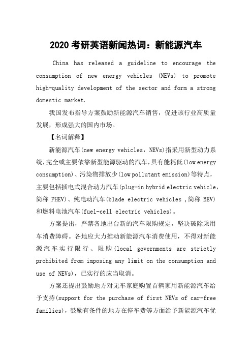
2020考研英语新闻热词:新能源汽车China has released a guideline to encourage the consumption of new energy vehicles (NEVs) to promote high-quality development of the sector and form a strong domestic market.我国发布指导方案鼓励新能源汽车销售,促进该行业高质量发展,形成强大的国内市场。
【名词解释】新能源汽车(new energy vehicles,NEVs)指采用新型动力系统,完全或主要依靠新型能源驱动的汽车,具有能耗低(low energy consumption)、污染物排放少(low pollutant emission)等特点,主要包括插电式混合动力汽车(plug-in hybrid electric vehicle,简称PHEV)、纯电动汽车(blade electric vehicles ,简称BEV)和燃料电池汽车(fuel-cell electric vehicles)。
方案提出,严禁各地出台新的汽车限购规定,坚决破除乘用车消费障碍。
各地应大力推动新能源汽车消费使用,不得对新能源汽车实行限行、限购(local governments are strictly prohibited from imposing any limit on the consumption and use of NEVs),已实行的应当取消。
方案还提出鼓励地方对无车家庭购置首辆家用新能源汽车给予支持(support for the purchase of first NEVs of car-free families),鼓励有条件的地方在停车费等方面给予新能源汽车优惠等。
此外,方案也提出了大幅降低新能源汽车成本(lower the cost of NEVs production)、稳步推动智能汽车创新发展(promote innovative development of smart vehicles)、持续提升汽车节能环保性能(increase energy efficiency)等方面的内容。
Electric vehicles(电动汽车)

Shanghai electric bus new energy technology limited company.
• the pioneer of battery quick change, • Electric vehicle separation,Quick change,
The battery replacement workshop in 2008 Olympic Games
3、Quick change mode.
• Replace the vehicle battery directly. • Change electric time and fuel automobile refueling time are similar, need about 5 ~ 10 min. • Special battery replacement station.
Hang zhou chelizi Intelligent technology limited company
• Time-sharing self-service rental(分时自助租赁)
• Through the APP or micro letter can achieve the function of
An ideal vehicle
• The energy conversion efficiency of the fuel cell is 2~3 times higher
than the internal combustion engine. • approximate zero emissions. • reduce greenhouse gas emissions. • Improve fuel economy.
新能源汽车专业英语 第1章 新能源汽车概述
1.1 The Development of Electric Vehicles
In 1901, Ferdinand Porsche developed the LohnerPorsche Mixte Hybrid, the first gasoline-electric hybrid automobile in the world. It was originally an electric-powered vehicle and then a gasoline engine was added to recharge the battery. Another hybrid car that used both a gasoline engine and an electric motor to power the vehicle was built by Woods Motor Company of Chicago in 1916, Illinois, and was called the “Woods Dual Power”.
from the ground up
从头开始
gasoline engine
汽油机
gasoline-electric hybrid automobile 汽油-电动混合动力汽车
hand crank horseless carriage
起动摇把 无马的马车,老式汽车
1.1 The Development of Electric Vehicles
New Words and Phrases hybrid car
混合动力汽车
hydrogen fuel cell
氢燃料电池
lithium-ion battery
新能源汽车 new energy vehicle

新能源汽车new energy vehicleChina has released a guideline to encourage the consumption of new energy vehicles(NEVs) to promote high-quality development of the sector and form a strong domestic market. 我国发布指导方案鼓励新能源汽车销售,促进该行业高质量发展,形成强大的国内市场。
【名词解释】新能源汽车(new energy vehicles,NEVs)指采用新型动力系统,完全或主要依靠新型能源驱动的汽车,具有能耗低(low energy consumption)、污染物排放少(low pollutant emission)等特点,主要包括插电式混合动力汽车(plug-in hybrid electric vehicle,简称PHEV)、纯电动汽车(battery electric vehicles ,简称BEV)和燃料电池汽车(fuel-cell electric vehicles)。
方案提出,严禁各地出台新的汽车限购规定,坚决破除乘用车消费障碍。
各地应大力推动新能源汽车消费使用,不得对新能源汽车实行限行、限购(local governments are strictly prohibited from imposing any limit on the consumption and use of NEVs),已实行的应当取消。
方案还提出鼓励地方对无车家庭购置首辆家用新能源汽车给予支持(support for the purchase of first NEVs of car-free families),鼓励有条件的地方在停车费等方面给予新能源汽车优惠等。
此外,方案也提出了大幅降低新能源汽车成本(lower the cost ofNEVs production)、稳步推动智能汽车创新发展(promote innovative development of smart vehicles)、持续提升汽车节能环保性能(increase energy efficiency)等方面的内容。
纯电动汽车术语解释

纯电动汽车术语解释纯电动汽车(Blade Electric Vehicles,简称BEV)是指仅依靠电力驱动的汽车。
这种汽车的主要特点是不排放尾气,不产生噪音,相比传统燃油车具有更高的能效和更低的维护成本。
以下是对纯电动汽车相关术语的详细解释:1、电池系统:纯电动汽车的核心部分,负责储存和提供电能。
电池系统的性能直接决定了车辆的续航里程、充电时间和电池寿命。
2、续航里程:指纯电动汽车在单次充电后所能行驶的最大距离。
这是评价电动汽车性能的重要指标,也是消费者选择购买的重要参考因素。
3、充电时间:指纯电动汽车电池从完全放电到充满电所需的时间。
快充和慢充是两种主要的充电方式。
快充通常可以在几十分钟内充满80%的电量,而慢充则需要数小时甚至更长时间。
4、驱动系统:指纯电动汽车的电动机及其控制系统。
电动机将电能转化为机械能,驱动车辆前进。
电动机的功率和扭矩决定了车辆的动力性能。
5、能量回收系统:在车辆制动或滑行时,能量回收系统能够将原本会损失的能量转化为电能并储存回电池中,从而提高能源利用效率。
6、车身结构:纯电动汽车的车身结构和传统燃油车有所不同,以适应电池布局和新的驱动方式。
例如,有些纯电动汽车采用了承载式车身和非承载式车身结构。
7、智能化:纯电动汽车作为新一代汽车,与智能化技术紧密结合。
智能化的纯电动汽车配备了各种传感器和高级算法,可以实现自动驾驶、智能导航、车联网等功能。
8、政策支持:许多国家和地区对纯电动汽车给予政策上的支持,如减免购置税、免费充电等,以鼓励消费者购买和使用纯电动汽车。
9、基础设施建设:为了支持纯电动汽车的普及,需要建设相应的充电设施,包括家庭充电桩、公共充电站等。
充电设施的覆盖范围和便利程度对纯电动汽车的发展至关重要。
10、环保性:相比传统燃油车,纯电动汽车几乎不产生尾气和噪音污染,对环境更加友好。
同时,纯电动汽车的使用可以减少对化石燃料的依赖,有助于减缓全球气候变化。
总体来说,纯电动汽车代表了未来交通出行的发展方向,具有广阔的市场前景。
电动汽车英文缩写汇总

电动汽车英文缩写汇总A Comprehensive List of Electric Vehicle Abbreviations.The rise of electric vehicles (EVs) has led to a proliferation of abbreviations and acronyms related to this emerging technology. As the industry continues to evolve,it's important to stay up-to-date with these terms to facilitate communication and understanding. In this article, we will provide a comprehensive list of electric vehicle abbreviations to help you navigate the EV landscape.1. EV (Electric Vehicle): This is the umbrella term for any vehicle that is primarily powered by electricity,rather than fossil fuels. EVs include pure electricvehicles (BEVs), plug-in hybrid electric vehicles (PHEVs), extended-range electric vehicles (EREVs), and fuel cell vehicles (FCVs).2. BEV (Battery Electric Vehicle): A vehicle that is powered solely by electricity stored in batteries. Thesevehicles have no internal combustion engine and rely entirely on batteries for propulsion.3. PHEV (Plug-in Hybrid Electric Vehicle): A vehicle that combines a traditional internal combustion engine with an electric motor and battery pack. PHEVs can be charged from an external power source and have the ability to operate in both electric and hybrid modes.4. EREV (Extended-Range Electric Vehicle): A type of EV that uses a small battery pack for daily driving and a larger, secondary battery pack or generator to extend the range when needed. This allows for longer driving distances without the need for frequent charging.5. FCV (Fuel Cell Vehicle): A vehicle that uses a fuel cell to convert hydrogen into electricity, which powers the electric motor. FCVs produce only water as a byproduct of the reaction, making them emission-free.6. VCU (Vehicle Control Unit): The brain of the EV, responsible for managing and controlling various vehiclefunctions such as acceleration, braking, and steering. The VCU receives input from various sensors and actuators and makes decisions based on this information.7. MCU (Motor Control Unit): This unit controls the electric motor, managing its speed, torque, and direction. The MCU receives signals from the VCU and adjusts themotor's performance accordingly.8. PDU/HVDU (Power Distribution Unit/High Voltage Distribution Unit): These units distribute power from the battery to various components of the vehicle, such as the motor, charging port, and auxiliary systems. The HVDU specifically handles the higher voltages required by EV components.9. HPC (High Power Charging): A type of charging system that allows for faster charging rates than traditional charging methods. HPC systems are typically used for public charging stations and can charge a vehicle in minutes rather than hours.10. SOC (State of Charge): A measure of the amount of charge remaining in a battery, expressed as a percentage. For example, a battery with a SOC of 80% has 80% of its capacity remaining.11. DOD (Depth of Discharge): A measure of how much a battery has been discharged since its last full charge. It is expressed as a percentage and represents the amount of battery capacity that has been used.12. SOH (State of Health): A measure of a battery's overall condition and performance. SOH takes into account factors such as battery capacity, health, and performance degradation over time.13. BMS (Battery Management System): A system that monitors and manages the battery pack, ensuring optimal performance and safety. The BMS monitors various parameters such as voltage, temperature, and current flow to prevent overcharging, overdischarging, and other potential safety issues.As the EV industry continues to grow and evolve, it's likely that we will encounter even more abbreviations and acronyms. Staying up-to-date with these terms is crucial for understanding and participating in the conversation about electric vehicles.。
新能源汽车英文
新能源汽车英文New Energy VehiclesIntroduction:New Energy Vehicles (NEVs) are vehicles that are powered by alternative energy sources other than fossil fuels, such as electricity, hydrogen, solar, or wind power. They are considered to be a crucial solution to combatting climate change and reducing air pollution caused by traditional internal combustion engine vehicles. In recent years, there has been a global push for the adoption of NEVs to promote a more sustainable and eco-friendly mode of transportation.Advantages of New Energy Vehicles:1. Environmental Benefits: One of the primary advantages of NEVs is their reduced carbon footprint. Unlike conventional vehicles, NEVs do not emit harmful greenhouse gases that contribute to global warming, making them an eco-friendly choice. Additionally, NEVs also help reduce air pollution in urban areas, improving the overall air quality and public health.2. Energy Efficiency: NEVs are more energy-efficient than traditional vehicles. Electric vehicles (EVs), for example, convert about 80% of the electrical energy from the grid to power at the wheels, while traditional internal combustion engine vehicles only have an energy conversion efficiency of around 20%.3. Lower Operating Costs: NEVs typically have lower operating costs compared to conventional vehicles. Electric vehicles have lower maintenance costs since they have fewer moving parts anddo not require engine oil changes, timing belt replacements, or transmission repairs. Furthermore, the cost of running an NEV is significantly lower due to cheaper fuel or electricity prices compared to gasoline or diesel.4. Technological Innovation: The development of NEVs has fostered technological advancements in battery technology, electric motor efficiency, charging infrastructure, and energy management systems. This innovation has a positive ripple effect on other industries, such as renewable energy and smart grid systems, creating new opportunities and driving economic growth. Promotion and Adoption of New Energy Vehicles:1. Government Incentives: Many countries around the world provide various incentives to promote the adoption of NEVs. These incentives can include tax credits, subsidies, and grants that reduce the purchase price of NEVs, making them more affordable for consumers. Additionally, some regions offer preferential policies, such as free parking, access to bus lanes, and exemption from road tolls or congestion charges for NEV owners.2. Charging Infrastructure: To encourage the wider adoption of NEVs, a reliable and extensive charging infrastructure needs to be in place. Governments and private companies are investing in the construction of public charging stations in cities, residential areas, and highways to provide convenient access to charging facilities for NEV owners.3. Research and Development: Continued investment in research and development is crucial to improve the performance, range, andaffordability of NEVs. Governments, automotive companies, and research institutions are collaborating to enhance battery technologies, develop fast-charging solutions, and optimize the energy efficiency of NEVs.Conclusion:New Energy Vehicles offer significant environmental, economic, and technological benefits. With ongoing advancements in battery technology and charging infrastructure, NEVs are becoming more practical and affordable for consumers. Governments, private companies, and individuals all have a role to play in promoting and adopting NEVs to achieve a more sustainable and clean transportation sector. By transitioning to NEVs, we can reduce our reliance on fossil fuels, mitigate climate change, and create a cleaner and healthier future for generations to come.。
byd组成英文短语 -回复
byd组成英文短语-回复1. BYD电动汽车(BYD electric cars)2. BYD污染控制(BYD pollution control)3. BYD电池技术(BYD battery technology)4. BYD燃料电池(BYD fuel cell)5. BYD智能交通(BYD intelligent transportation)6. BYD新能源汽车(BYD new energy vehicles)7. BYD太阳能充电(BYD solar charging)8. BYD可再生能源(BYD renewable energy)9. BYD绿色出行(BYD green transportation)10. BYD智能物流(BYD smart logistics)11. BYD智能制造(BYD smart manufacturing)12. BYD电池回收(BYD battery recycling)13. BYD智慧城市(BYD smart city)14. BYD高科技产品(BYD high-tech products)15. BYD电动巴士(BYD electric buses)16. BYD电动摩托车(BYD electric motorcycles)17. BYD空气净化器(BYD air purifier)18. BYD光伏发电系统(BYD photovoltaic power generation system)19. BYD智能家居(BYD smart home)20. BYD智能电网(BYD smart grid)21. BYD可持续发展(BYD sustainable development)22. BYD环保技术(BYD environmental protection technology)23. BYD环境友好(BYD environmentally friendly)24. BYD智能农业(BYD smart agriculture)25. BYD电动叉车(BYD electric forklift)。
新能源汽车newenergyvehicle

新能源汽车newenergyvehicle新能源汽车new energy vehicleChina has released a guideline to encourage the consumption of new energy vehicles(NEVs) to promote high-quality development of the sector and form a strong domestic market. 我国发布指导方案鼓励新能源汽车销售,促进该行业高质量发展,形成强大的国内市场。
【名词解释】新能源汽车(new energy vehicles,NEVs)指采用新型动力系统,完全或主要依靠新型能源驱动的汽车,具有能耗低(low energy consumption)、污染物排放少(low pollutant emission)等特点,主要包括插电式混合动力汽车(plug-in hybrid electric vehicle,简称PHEV)、纯电动汽车(battery electric vehicles ,简称BEV)和燃料电池汽车(fuel-cell electric vehicles)。
方案提出,严禁各地出台新的汽车限购规定,坚决破除乘用车消费障碍。
各地应大力推动新能源汽车消费使用,不得对新能源汽车实行限行、限购(local governments are strictly prohibited from imposing any limit on the consumption and use of NEVs),已实行的应当取消。
方案还提出鼓励地方对无车家庭购置首辆家用新能源汽车给予支持(support for the purchase of first NEVs of car-free families),鼓励有条件的地方在停车费等方面给予新能源汽车优惠等。
此外,方案也提出了大幅降低新能源汽车成本(lower the cost ofNEVs production)、稳步推动智能汽车创新发展(promote innovative development of smart vehicles)、持续提升汽车节能环保性能(increase energy efficiency)等方面的内容。
- 1、下载文档前请自行甄别文档内容的完整性,平台不提供额外的编辑、内容补充、找答案等附加服务。
- 2、"仅部分预览"的文档,不可在线预览部分如存在完整性等问题,可反馈申请退款(可完整预览的文档不适用该条件!)。
- 3、如文档侵犯您的权益,请联系客服反馈,我们会尽快为您处理(人工客服工作时间:9:00-18:30)。
湖北文理学院毕业设计(论文)英文翻译题目在采用PWM逆变器下的变速感应电机驱动器中的传导性排放轴承电流的减少和鉴定专业机械设计制造及其自动化班级机制0911姓名杨成杰学号2009116140指导教师职称周立文(学校)冯南(企业)2013年5月10日┊┊┊┊┊┊┊┊┊┊┊┊┊装┊┊┊┊┊订┊┊┊┊┊线┊┊┊┊┊┊┊┊┊┊┊┊┊Minimization and identification of conducted emission bearing current in variable speed induction motor drives using PWM inverterAbstract. The recent increase in the use of speed control of ac induction motor for variable speed drive using pulse width modulation (PWM) inverter is due to the advent of modern power electronic devices and introduction of microprocessors. There are many advantages of using ac induction motor for speed control applications in process and aerospace industries, but due to fast switching of the modem power electronic devices,the parasitic coupling produces undesirable effects. The undesirable effects include radiated and conducted electromagnetic interference (EMI) which adversely affect nearby computers, electronic/electrical instruments and give rise to the flow of bearing current in the induction motor. Due to the flow of bearing current in the induction motor,electrical discharge machining takes place in the inner race of the bearing which reduces the life of the bearing. In high power converters and inverters, the conducted and radiated emissions become a major concern. In this paper, identification of bearing current due to conducted emission, the measurement of bearing current in a modified induction motor and to minimize the bearing current are discussed. The standard current probe, the standard line impedance stabilization network (LISN)), the electronics interface circuits are used to measure high frequency common mode current,bearing current and to minimize the conducted noise from the system. The LISN will prevent the EMI noise entering the system from the supply source by conductive methods, at the same time prevents the EMI generated if any due to PWM, fast switching in the system, will not be allowed to enter the supply line. For comparing the results with Federal Communications Commission (FCC) and Special Committee on Radio Interference (CISPR) standards, the graphs are plotted with frequency Vs,line voltage in dB μV,common mode voltage in dB μV and the bearing current in dBμA without and with minimizing circuits.Keywords. EMI;a.c.drives; bearing current.┊┊┊┊┊┊┊┊┊┊┊┊┊装┊┊┊┊┊订┊┊┊┊┊线┊┊┊┊┊┊┊┊┊┊┊┊┊1.IntroductionWith the development of power electronic devices like the insulated gate bi-polar transistor (IGBT), the power MOSFET and the advances in microprocessors, the ac induction motor is becoming popular in variable speed drives with PWM inverter circuits. Since the rise time and fall time of the IGBT are less than 200 nanoseconds, the dissipation loss across the device becomes very less and there by increases the performance of the circuit. However, due to the fast switching action of the device the dw/dt of the inverter output becomes large. This high dw/dX voltage transition coupled with parasitic stray capacitance in the system causes high frequency line to ground current or common mode current and hence bearing current; introducing large EMI in the system.In figure 1,Ilg (the magnitude of ground current) depends on the cable capacitance, machine capacitance,parasitic capacitance of the devices, the output voltage rise time (tr ise) and the system voltage, V oltage gets induced in the rotor shaft of the induction motor due to fast switching. This induced voltage generates circulating current and flows to the ground through the bearing resulting in an electrical discharge machining (EDM) action at the inner race of the bearing.Due to the EDM, the life of the bearing reduces. The common mode voltage Vng (figure 1) can be measured from the star point of the stator winding of the induction motor (IM) or connected node of three 1MO resistors to the ground in case of the IM connected in delta. The reasons for common mode voltage generation are already discussed.It is noted that the sum of sinusoidal balanced phase voltages in a 3-phase IM at the star point is equal to zero. Therefore,Vng=(Van+Vbn+Vcn)/3 ⑴Common mode current=Cdν/dt⑵┊┊┊┊┊┊┊┊┊┊┊┊┊装┊┊┊┊┊订┊┊┊┊┊线┊┊┊┊┊┊┊┊┊┊┊┊┊Where ‘C’ is the total capacitance of the system and V an,V bn and V cn are the voltages between the respective phases and the star point in the stator winding2.Existing conducted emission, bearing current identification and measurement methodsV arious methods have been proposed to reduce the conducted emission common mode voltage and the measurement of bearing current. An output reactor connected to the inverter out put reduces the dv/dt of the inverter output voltage, which in turn reduces the common mode voltage at the star point of the IM and the flow of bearing current. Wious configurations of L-C filter have been reported. The inductance ‘L,and capacitance ‘C’ are designed according to the permitted insertion loss for the given power rating of the inverter. The draw back of the filter method is the voltage drop across the filter.In the passive filter method, the transformer secondary should be isolated for its successful operation and this is not possible in many process/engineering industries. An active common noise canceller has been tried to eliminate the conducted emission common mode voltage produced by the PWM inverter. The active common noise canceller superimposes a compensating voltage applied at the star point. This has the same amplitude as the common mode voltage produced by the PWM inverter but has opposite polarity; hence the common mode voltage applied to the load is cancelled completely. However, this method is suitable only for low voltage/power applications due to the resistive current sensor.Julian proposed a filter circuit for reducing the common mode voltage.This filter circuit is based on current sensing and it operates a fast transistor amplifier for the current compensation. Significant attenuation of the common mode voltage occurs.The method presented in this paper is different from earlier methods. Here,the phase current is sensed by the individual current transformer (CT) and is suitable for any voltage level. Since the CT is used for sensing the phase current there is no voltage drop in the sensor there by there is no reduction of terminal voltage applied to the IM.In tiidr circuit, the primary winding of the transformer is connected in series in each of the phases. Since the circuit uses the transformer, there is voltage drop due to the phase current of the IM, hence the terminal voltage applied to the IM gets reduced. The circuit is also used to reduce the common mode voltage and the common mode current at the star point of the IM. But this circuit is useful for the low voltage and low power applications.In the present work,the standard LISN,the standard current probes are used and the results are compared without and with the common mode voltage reduction circuits for the PWM inverter used for variable speed ac IM drives.┊┊┊┊┊┊┊┊┊┊┊┊┊装┊┊┊┊┊订┊┊┊┊┊线┊┊┊┊┊┊┊┊┊┊┊┊┊Julian proposed a filter circuit for reducing the common mode voltage.This filter circuit is based on current sensing and it operates a fast transistor amplifier for the current compensation. Significant attenuation of the common mode voltage occurs.The method presented in this paper is different from earlier methods. Here,the phase current is sensed by the individual current transformer (CT) and is suitable for any voltage level. Since the CT is used for sensing the phase current there is no voltage drop in the sensor there by there is no reduction of terminal voltage applied to the IM.In tiidr circuit,the primary winding of the transformer is connected in series in each of the phases. Since the circuit uses the transformer, there is voltage drop due to the phase current of the IM, hence the terminal voltage applied to the IM gets reduced. The circuit is also used to reduce the common mode voltage and the common mode current at the star point of the IM. But this circuit is useful for the low voltage and low power applications.In the present work,the standard LISN,the standard current probes are used and the results are compared without and with the common mode voltage reduction circuits for the PWM inverter used for variable speed ac IM drives.┊┊┊┊┊┊┊┊┊┊┊┊┊装┊┊┊┊┊订┊┊┊┊┊线┊┊┊┊┊┊┊┊┊┊┊┊┊在采用PWM逆变器下的变速感应电机驱动器中的传导性排放轴承电流的减少和鉴定摘要由于现代电力电子器件的出现和微处理器的采用,交流异步电机的速度控制被广泛应用了,这种使用用于使用PWM逆变器的变速驱动器中。