611222中文资料
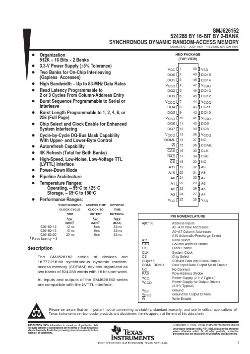
SMJ626162资料
IMPORTANT NOTICETexas Instruments and its subsidiaries (TI) reserve the right to make changes to their products or to discontinue any product or service without notice, and advise customers to obtain the latest version of relevant information to verify, before placing orders, that information being relied on is current and complete. All products are sold subject to the terms and conditions of sale supplied at the time of order acknowledgement, including those pertaining to warranty, patent infringement, and limitation of liability.TI warrants performance of its semiconductor products to the specifications applicable at the time of sale in accordance with TI’s standard warranty. Testing and other quality control techniques are utilized to the extent TI deems necessary to support this warranty. Specific testing of all parameters of each device is not necessarily performed, except those mandated by government requirements.CERTAIN APPLICATIONS USING SEMICONDUCTOR PRODUCTS MAY INVOLVE POTENTIAL RISKS OF DEATH, PERSONAL INJURY, OR SEVERE PROPERTY OR ENVIRONMENTAL DAMAGE (“CRITICAL APPLICATIONS”). TI SEMICONDUCTOR PRODUCTS ARE NOT DESIGNED, AUTHORIZED, OR WARRANTED TO BE SUITABLE FOR USE IN LIFE-SUPPORT DEVICES OR SYSTEMS OR OTHER CRITICAL APPLICATIONS. INCLUSION OF TI PRODUCTS IN SUCH APPLICATIONS IS UNDERSTOOD TO BE FULLY AT THE CUSTOMER’S RISK.In order to minimize risks associated with the customer’s applications, adequate design and operating safeguards must be provided by the customer to minimize inherent or procedural hazards.TI assumes no liability for applications assistance or customer product design. TI does not warrant or represent that any license, either express or implied, is granted under any patent right, copyright, mask work right, or other intellectual property right of TI covering or relating to any combination, machine, or process in which such semiconductor products or services might be or are used. TI’s publication of information regarding any third party’s products or services does not constitute TI’s approval, warranty or endorsement thereof.Copyright © 1999, Texas Instruments Incorporated。
PT2262、PT2272 编码解码芯片中文资料
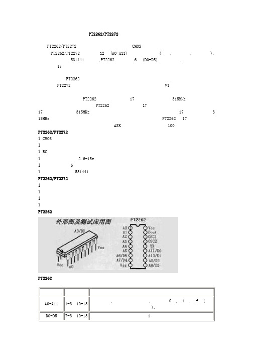
PT2262/PT2272编码解码芯片中文资料PT2262/PT2272是台湾普城公司生产的一种CMOS工艺制造的低功耗低价位通用编解码电路,PT2262/PT2272最多可有12位(A0-A11)三态地址端管脚(悬空,接高电平,接低电平),任意组合可提供531441地址码,PT2262最多可有6位(D0-D5)数据端管脚,设定的地址码和数据码从17脚串行输出,可用于无线遥控发射电路。
编码芯片PT2262发出的编码信号由:地址码、数据码、同步码组成一个完整的码字,解码芯片PT2272接收到信号后,其地址码经过两次比较核对后,VT脚才输出高电平,与此同时相应的数据脚也输出高电平,如果发送端一直按住按键,编码芯片也会连续发射。
当发射机没有按键按下时,PT2262不接通电源,其17脚为低电平,所以315MHz的高频发射电路不工作,当有按键按下时,PT2262得电工作,其第17脚输出经调制的串行数据信号,当17脚为高电平期间315MHz的高频发射电路起振并发射等幅高频信号,当17脚为低平期间3 15MHz的高频发射电路停止振荡,所以高频发射电路完全收控于PT2262的17脚输出的数字信号,从而对高频电路完成幅度键控(ASK调制)相当于调制度为100%的调幅。
PT2262/PT2272特点l CMOS工艺制造,低功耗l 外部元器件少l RC振荡电阻l 工作电压范围宽:2.6-15vl 数据最多可达6位l 地址码最多可达531441种PT2262/PT2272应用范围l 车辆防盗系统l 家庭防盗系统l 遥控玩具l 其他电器遥控PT2262 引脚图:PT2262管脚说明:名称管脚说明A0-A11 1-8、10-13 地址管脚,用于进行地址编码,可置为“0”,“1”,“f”(悬空),D0-D5 7-8、10-13 数据输入端,有一个为“1”即有编码发出,内部下拉Vcc 18 电源正端(+)Vss 9 电源负端(-)TE 14 编码启动端,用于多数据的编码发射,低电平有效;OSC1 16 振荡电阻输入端,与OSC2所接电阻决定振荡频率;OSC2 15 振荡电阻振荡器输出端;Dout 17 编码输出端(正常时为低电平)在具体的应用中,外接振荡电阻可根据需要进行适当的调节,阻值越大振荡频率越慢,编码的宽度越大,发码一帧的时间越长.PT2262参数PT2272 解码电路引脚图:名称管脚说明A0-A11 1-8、10-13 地址管脚,用于进行地址编码,可置为“0”,“1”,“f”(悬空),必须与2262一致,否则不解码D0-D5 7-8、10-13 地址或数据管脚,当做为数据管脚时,只有在地址码与2262一致,数据管脚才能输出与2262数据端对应的高电平,否则输出为低电平,锁存型只有在接收到下一数据才能转换Vcc 18 电源正端(+)Vss 9 电源负端(-)DIN 14 数据信号输入端,来自接收模块输出端OSC1 16 振荡电阻输入端,与OSC2所接电阻决定振荡频率;OSC2 15 振荡电阻振荡器输出端;VT 17解码有效确认输出端(常低)解码有效变成高电平(瞬态)PT2272解码芯片有不同的后缀,表示不同的功能,有L4/M4/L6/M6之分,其中L表示锁存输出,数据只要成功接收就能一直保持对应的电平状态,直到下次遥控数据发生变化时改变。
6222中文资料

HCMOS OUTPUT CHARACTERISTICS
PARAMETER LOAD Voltage (High) (Low) Current (High) (Low) Duty Cycle at 50% of Vcc Rise / Fall Time 10% to 90% Start-Up Time Jitter (BW=10Hz to 20MHz) Jitter (BW=12kHz to 20MHz) MINIMUM 0.9Vcc -4 45 NOMINAL MAXIMUM 15 0.1Vcc 4 55 5 10 5 1 UNITS pF Vdc Vdc mA mA % nS h) (Vol) (Ioh) (Ioh)
50 -
PACKAGE CHARACTERISTICS
Package Hermetically sealed ceramic package and metal cover
TABLE 6.0
POWER SAVING FUNCTION: 10uA WHEN DISABLED CERAMIC SURFACE MOUNT PACKAGE TAPE AND REEL PACKAGING
TABLE 5.0 NOTE
FEATURES 2.5V OPERATION 1.8 to 50MHz TEMPERATURE RANGE: -40 to 85°C OVERALL FREQUENCY TOLERANCE:±50ppm TRI-STATE ENABLE/DISABLE FUNCTION
元器件交易网
THE CONNOR-WINFIELD CORP.
2111 COMPREHENSIVE DRIVE. AURORA, IL 60505. FAX (630) 851-5040. PHONE (630) 851-4722.
626229资料
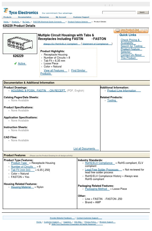
626229 Product DetailsHome | Customer Support | Suppliers | Site Map | Privacy Policy | Browser Support© 2008 Tyco Electronics Corporation All Rights Reserved SearchProducts Documentation Resources My Account Customer SupportHome > Products > By Type > FASTON Electrical Quick Connects > Product Feature Selector > Product Details626229Active Multiple Circuit Housings with Tabs &Receptacles Including FASTIN-FASTONAlways EU RoHS/ELV Compliant (Statement of Compliance)Product Highlights:?Receptacle Housing?Number of Circuits = 8?Tab Fit = 6.35 mm?Loose Piece?Color = NaturalView all Features | Find SimilarProductsCheck Pricing &AvailabilitySearch for ToolingProduct FeatureSelectorContact Us AboutThis ProductQuick LinksDocumentation & Additional InformationProduct Drawings:?HOUSING, 8 POSN., FASTIN-ON RECEPT.(PDF, English)Catalog Pages/Data Sheets:?None AvailableProduct Specifications:?None AvailableApplication Specifications:?None AvailableInstruction Sheets:?None AvailableCAD Files:?None AvailableList all Documents Additional Information:?Product Line InformationRelated Products:?ToolingProduct Features (Please use the Product Drawing for all design activity)Product Type Features:?Product Type = Receptacle Housing ?Number of Circuits = 8?Tab Fit (mm [in]) = 6.35 [.250]?Color = Natural?FASTON = YesHousing Related Features:?Housing Material = Nylon Industry Standards:?RoHS/ELV Compliance = RoHS compliant, ELVcompliant?Lead Free Solder Processes = Not reviewed forlead free solder process?RoHS/ELV Compliance History = Always wasRoHS compliantPackaging Related Features:?Packaging Method = Loose PieceOther:?Line = FASTIN-FASTON .250?Brand = AMPProvide Website Feedback | Contact Customer Support。
1762224资料
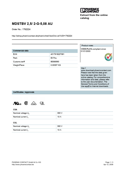
CSA Nominal voltage UN Nominal current IN CUL Nominal voltage UN Nominal current IN 300 V 10 A 300 V 10 A
PHOENIX CONTACT GmbH & Co. KG http://www.phoenixcontact.de
Page 1 / 3 Apr 12, 2008
元器件交易网
MDSTBV 2,5/ 2-G-5,08 AU Order No.: 1762224
http://eshop.phoenixcontact.de/phoenix/treeViewClick.do?UID=1762224
© 2008 Phoenix Contact Technical modifications reserved;
PHOENIX CONTACT GmbH & Co. KG http://www.phoenixcontact.de
Page 3 / 3 Apr 12, 2008
UL Nominal voltage UN Nominal current IN Certification 300 V 10 A CB, CSA, CUL, UL, VDGmbH & Co. KG http://www.phoenixcontact.de
Page 2 / 3 Apr 12, 2008
元器件交易网
Extract from the online catalog
MDSTBV 2,5/ 2-G-5,08 AU
Order No.: 1762224
http://eshop.phoenixcontact.de/phoenix/treeViewClick.do?UID=1762224
0190020022;中文规格书,Datasheet资料

This document was generated on 08/13/2012PLEASE CHECK FOR LATEST PART INFORMATIONPart Number:19002-0022Status:ActiveDescription:Avikrimp™ Fully Insulated Quick Disconnect, Female, for 18-22 AWG Wire, Mylar TapeDocuments:Drawing (PDF)Product Specification PS-19902-015 (PDF)Product Specification PS-19902-011 (PDF)RoHS Certificate of Compliance (PDF)Product Specification PS-19902-014 (PDF)Agency CertificationTUV R75108ULE79133GeneralProduct Family Quick Disconnects Series19002Crimp Quality Equipment YesProduct Name Avikrimp™Type Quick Disconnect UPC800753027268PhysicalBarrel Type Closed Flammability 94V-2GenderFemale Glow-Wire Compliant NoInsulationNylon (PA)Lock to Mating Part None Material - Metal Brass Net Weight 0.862/g OrientationStraightPackaging TypeAdhesive Tape on Reel Polarized to Mating Part NoTab Thickness 0.81mm Tab Width5.21mmTemperature Range - Operating -65°C to +105°C Wire Insulation Diameter 3.17mm max.Wire Size AWG 18, 20, 22Wire Size mm²0.35 - 0.80ElectricalVoltage - Maximum300V Material InfoOld Part NumberAA-5285TReference - Drawing NumbersProduct Specification PS-19902-011, PS-19902-014, PS-19902-015Sales DrawingSD-19002-003Seriesimage - Reference onlyEU RoHSChina RoHSELV and RoHS Compliant REACH SVHCContains SVHC: No Low-Halogen Status Low-HalogenNeed more information on product environmental compliance?Email productcompliance@For a multiple part number RoHS Certificate of Compliance, click herePlease visit the Contact Us section for any non-product compliance questions.Search Parts in this Series 19002SeriesApplication Tooling | FAQTooling specifications and manuals are found by selecting the products below.Crimp Height Specifications are then contained in the Application Tooling Specification document.GlobalDescription Product #ATP Perishable Tool Kit Used in ATPPresses that Process Product on Tape 0192880028Mini-Mac™Applicator0638852000This document was generated on 08/13/2012PLEASE CHECK FOR LATEST PART INFORMATION/分销商库存信息: MOLEX 0190020022。
5082-A111-EE000资料
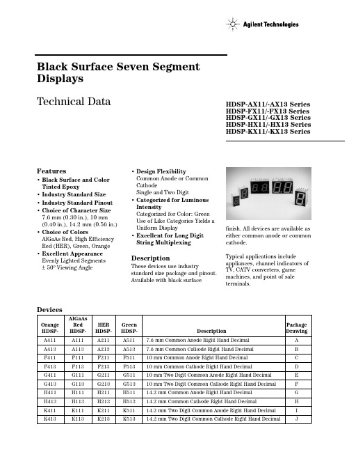
DevicesAlGaAs Orange Red HER Green Package HDSP-HDSP-HDSP-HDSP- DescriptionDrawingA411A111A211A5117.6 mm Common Anode Right Hand Decimal A A413A113A213A5137.6 mm Common Cathode Right Hand Decimal B F411F111F211F51110 mm Common Anode Right Hand Decimal C F413F113F213F51310 mm Common Cathode Right Hand Decimal D G411G111G211G51110 mm Two Digit Common Anode Right Hand Decimal E G413G113G213G51310 mm Two Digit Common Cathode Right Hand Decimal F H411H111H211H51114.2 mm Common Anode Right Hand Decimal G H413H113H213H51314.2 mm Common Cathode Right Hand Decimal H K411K111K211K51114.2 mm Two Digit Common Anode Right Hand Decimal I K413K113K213K51314.2 mm Two Digit Common Cathode Right Hand DecimalJBlack Surface Seven Segment Displays Technical DataFeatures• Black Surface and Color Tinted Epoxy• Industry Standard Size • Industry Standard Pinout • Choice of Character Size 7.6 mm (0.30 in.), 10 mm (0.40in.), 14.2 mm (0.56 in.)• Choice of ColorsAlGaAs Red, High Efficiency Red (HER), Green, Orange • Excellent Appearance Evenly Lighted Segments ±50° Viewing Angle• Design FlexibilityCommon Anode or Common CathodeSingle and Two Digit• Categorized for Luminous IntensityCategorized for Color: Green Use of Like Categories Yields a Uniform Display• Excellent for Long Digit String MultiplexingDescriptionThese devices use industrystandard size package and pinout.Available with black surfaceHDSP-AX11/-AX13 Series HDSP-FX11/-FX13 Series HDSP-GX11/-GX13 Series HDSP-HX11/-HX13 Series HDSP-KX11/-KX13 Seriesfinish. All devices are available as either common anode or common cathode.Typical applications includeappliances, channel indicators of TV, CATV converters, game machines, and point of sale terminals.Part Numbering System5082 -X X X X-X X X X XHDSP-X X X X-X X X X XMechanical Options[1]00: No Mechanical OptionColor Bin Options[1,2]0: No Color Bin LimitationMaximum Intensity Bin[1,2]0: No Maximum Intensity Bin LimitationMinimum Intensity Bin[1,2]0: No Minimum Intensity Bin LimitationDevice Configuration/Color[1]1: Common Anode3: Common CathodeDevice Specific Configuration[1]Refer to Respective DatasheetPackage[1]A: 7.6 mm (0.3 inch) Single Digit Seven Segment DisplayF: 10 mm (0.4 inch) Single Digit Seven Segment DisplayG: 10 mm (0.4 inch) Dual Digit Seven Segment DisplayH: 14.2 mm (0.56 inch) Single Digit Seven Segment DisplayK: 14.2 mm (0.56 inch) Dual Digit Seven Segment Display Notes:1. For codes not listed in the figure above, please refer to the respective datasheet or contact your nearestAgilent representative for details.2. Bin options refer to shippable bins for a part number. Color and Intensity Bins are typically restricted to 1bin per tube (exceptions may apply). Please refer to respective datasheet for specific bin limit information.Package Dimensions (7.6 mm Series)Internal Circuit DiagramPackage Dimensions (10 mm Series: Single)Internal Circuit DiagramPackage Dimensions (10 mm Series: Two Digit)Internal Circuit DiagramPackage Dimensions (14.2 mm Series: Single)Internal Circuit DiagramPackage Dimensions (14.2 mm Series: Two Digit)Internal Circuit Diagram2DIGIT NO. 1 CATHODE1Absolute Maximum RatingsAlGaAs Red HER/Orange GreenHDSP-X11X HDSP-X21X/X41X HDSP-X51X Description Series Series Series Units Average Power per Segment37105105mW or DPPeak Forward Current per4590[1]90[3]mA Segment or DPDC Forward Current per15[5]30[2]30[4]mA Segment or DPOperating Temperature Range–20 to +100 –40 to +100°C Storage Temperature Range–55 to +100°C Reverse Voltage per 3.0V Segment or DPWave Soldering Temperature for250°C 3 Seconds (1.60 mm [0.063 in.]below Body)Notes:1. See Figure 5 to establish pulsed conditions.2. Derate above 53°C at 0.45 mA/°C (see Figure 7).3. See Figure 6 to establish pulsed conditions.4. Derate above 39°C at 0.37 mA/°C (see Figure 7).5. Derate above 91°C at 0.53 mA/°C (see Figure 1).Electrical/Optical Characteristics at T A = 25°CAlGaAs RedDevice SeriesHDSP-Parameter Symbol Min.Typ.Max.Units Test Conditions A11X Luminous Intensity/Segment[1,2]I V315600µcd I F = 1 mA (Digit Average)3600I F = 5 mAF11X, G11X330650I F = 1 mA3900I F = 5 mAH11X, K11X400700I F = 1 mA4200I F = 5 mAAll Devices Forward Voltage/Segment or DP V F 1.6 2.0V I F = 1 mA1.7I F = 5 mA1.822I F = 20 mA PeakPeak WavelengthλP EAK645nmDominant Wavelength[3]λd637nmReverse Voltage/Segment or DP[4]V R 3.015V I R = 100 µATemperature Coefficient of∆V F/°C-2mV/°CV F/Segment or DPA11X Thermal Resistance LED RθJ-PIN255°C/W/Junction-to-Pin Seg.F11X, G11X320H11X, K12X400OrangeDevice SeriesHDSP-Parameter Symbol Min.Typ.Max.Units Test Conditions A41X Luminous Intensity/Segment I V0.70mcd I F = 5 mA (Segment Average)[1,2]F41X, G41X 1.0I F = 5 mAH41X, K41X 2.37I F = 10 mAAll Forward Voltage/Segment or DP V F 2.0 2.5V I F = 20 mA DevicesPeak WavelengthλPEAK600nmDominant Wavelength[3]λd603nmReverse Voltage/Segment or DP[4]V R 3.030V I R = 100 µATemperature Coefficient of∆V F/°C–2mV/°CV F/Segment or DPA41X Thermal Resistance LED RθJ-PIN200°C/W/Junction-to-Pin Seg.F41X, G41X320H41X, K41X345High Efficiency RedDevice SeriesHDSP-Parameter Symbol Min.Typ.Max.Units Test Conditions A21X Luminous Intensity/Segment[1,2]I V360980µcd I F = 5 mA (Digit Average)5390I F = 20 mAF21X, G21X4201200I F = 5 mAH21X, K21X9002800I F = 10 mA3700I F = 60 mA Peak:1/6 Duty Factor All Forward Voltage/Segment or DP V F 2.0 2.5V I F = 20 mA DevicesPeak WavelengthλPEAK635nmDominant Wavelength[3]λd626nmReverse Voltage/Segment or DP[4]V R 3.030V I R = 100 µATemperature Coefficient of∆V F/°C-2mV/°CV F/Segment or DPA21X Thermal Resistance LED RθJ-PIN200°C/W/Junction-to-Pin Seg.F21X, G21X320H21X, K21X345High Performance GreenDevice SeriesHDSP-Parameter Symbol Min.Typ.Max.Units Test ConditionsA51X Luminous Intensity/Segment[1,2]I V8603000µcd I F = 10 mA (Digit Average)6800I F = 20 mAF51X, G51X10303500I F = 10 mAH51X, K51X9002500I F = 10 mA3100I F = 60 mA Peak:1/6 Duty FactorAll Forward Voltage/Segment or DP V F 2.1 2.5V I F = 10 mADevicesPeak WavelengthλPEAK566nmDominant Wavelength[3,5]λd571577nmReverse Voltage/Segment or DP[4]V R 3.050V I R = 100 µATemperature Coefficient of∆V F/°C-2mV/°CV F/Segment or DPA51X Thermal Resistance LED RθJ-PIN200°C/W/Junction-to-Pin Seg.F51X, G51X320H51X, G51X345Notes:1. Case temperature of device immediately prior to the intensity measurement is 25°C.2. The digits are categorized for luminous intensity. The intensity category is designated by a letter on the side of the package.3. The dominant wavelength, λd, is derived from the CIE chromaticity diagram and is that single wavelength which defines the color ofthe device.4. Typical specification for reference only. Do not exceed absolute maximum ratings.5. Green (HDSP-A51X/F51X/G51X/H512X/K51X) series displays are categorized for dominant wavelength. The category is designated bya number adjacent to the luminous intensity category letter.Figure 3. Relative Luminous Intensity vs. DC Forward Current.Figure 4. Relative Efficiency (LuminousIntensity per Unit Current) vs. Peak Current.Figure 1. Maximum Allowable Average orDC Current vs. Ambient Temperature.Figure 2. Forward Current vs. Forward Voltage.16024681012142010090807060504030T – AMBIENT TEMPERATURE – °C AI A V E . M A X – M A X I M U M A V E R A G E F O R W A R D C U R R E N T P E R S E G M E N T – m AF 1201102018F 50.020.010.05.02.01.00.50.10.51.01.52.02.5V – FORWARD VOLTAGE – VF I – F O R W A R D C U R R E N TP E R S E G M E N T – m A20105210.50.20.10.10.20.51251020R E L A T I V E L U M I N O U S I N T E N S I T Y (N O R M A L I Z E D T O 1 A T 1 m A )I – FORWARD CURRENT PER SEGMENT – mAF I – PEAK FORWARD CURRENTPER SEGMENT – mAPEAK η –R E L A T I V E E F F I C I E N C Y – N O R M A L I Z E D T O 1 A T 1 m AP E A K 1.31.21.11.00.90.80.7AlGaAs RedHER, Green, OrangeFigure 7. Maximum Allowable DCCurrent vs. Ambient Temperature.Figure 8. Forward Current vs.Forward Voltage Characteristics.Figure 9. Relative Luminous Intensity vs. DC Forward Current.Figure 10. Relative Efficiency (Luminous Intensity per Unit Current) vs. Peak Current.40051015202530352010090807060504030T – AMBIENT TEMPERATURE – °CA I M A X – M A X I M U M D C C U R R E N T P E R S E G M E N T – m AD C 1201105045010080604020I – F O R W A R D C U R R E N T P E R S E G M E N T – m AF 2.04.03.01.0V –FORWARD VOLTAGE – VF 05.0ηP E A K – R E L A T I V E L U M I N O U S I N T E N S I T Y (N O R M A L I Z E D T O 1 A T 5 m A F O R H E R ,A N D T O 1 A T 10 m A F O R G R E E N )150108642205301025I – FORWARD CURRENT PER SEGMENT – mAF 0I – PEAK FORWARD CURRENTPER SEGMENT – mAPEAK ηP E A K – R E L A T I V E E F F I C I E N C Y (N O R M A L I Z E D T O 1 A T 5 m A F O R H E R ,A N D 10 m A F O R G R E E N )Figure 5. Maximum Tolerable Peak Currentvs. Pulse Duration – HER, Orange.Figure 6. Maximum Tolerable Peak Current vs. Pulse Duration – Green.R A T I O O F M A X I M U M O P E R A T I N G P E A K C U R R E N T T O T E M P E R A T U R E D E R A T E D D C C U R R E N TI P E A K F I M A X D C t – PULSE DURATION – µsP 101100DC R A T I O O F M A X I M U M O P E R A T I N G P E A K C U R R E N T T O T E M P E R A T U R E D E R A T E D D C C U R R E N TI P E A K FI M A X D C t – PULSE DURATION – µs P 101100DCHDSP-A1xx IV Bin Category Min.Max.E 0.3150.520F 0.4280.759G 0.621 1.16H 0.945 1.71I 1.40 2.56J 2.10 3.84K 3.14 5.75L 4.708.55Intensity Bin Limits (mcd)AlGaAs RedHDSP-F1xx/G1xx IV Bin Category Min.Max.D 0.3910.650E 0.5320.923F 0.755 1.39G 1.13 2.08H 1.703.14HDSP-H1xx/K1xx IV Bin Category Min.Max.C 0.4150.690D 0.5650.990E 0.810 1.50F 1.20 2.20G 1.80 3.30H 2.73 5.00I 4.097.50OrangeHDSP-A41XIV Bin Category MinMaxA 0.2840.433B 0.3540.541C 0.4430.677D 0.5540.846E 0.692 1.057F 0.856 1.322G 1.082 1.652H 1.352 2.066I 1.692 2.581J 2.114 3.227K 2.641 4.034L 3.300 5.042M 4.127 6.303N 5.1577.878HDSP-F41X/G41XIV Bin Category MinMaxC 0.4850.890D 0.728 1.333E 1.091 2.000F 1.636 3.000G 2.454 4.500H 3.6826.751HDSP-H41X/K41XIV Bin Category MinMaxB 0.77 1.17C 0.95 1.45D 1.19 1.82E 1.49 2.27F 1.85 2.89G 2.32 3.54H 2.904.43Intensity Bin Limits (mcd), continued HERMin.Max.B0.3420.630C0.5160.946D0.774 1.418E 1.160 2.127F 1.740 3.190G 2.610 4.785H 3.9157.177Min.Max.C0.4850.890D0.728 1.333E 1.091 2.000F 1.636 3.000G 2.454 4.500H 3.682 6.751Min.Max.E0.91 1.67F 1.37 2.51G 2.05 3.76H 3.08 5.64I 4.628.64J 6.9312.70K10.3919.04Contrast EnhancementFor information on contrast enhancement, please see Application Note 1015.Soldering/CleaningFor information on soldering LEDs, please refer to Application Note 1029.Electrical/OpticalFor more information onelectrical/optical characteristics,please see Application Note 1005.Color CategoriesNote:All categories are established for classification of products. Products may not be available in all categories. Please contact your Agilent representatives for further clarification/information.HDSP-A5xx IV Bin Category Min.Max.H 0.86 1.58I 1.29 2.37J 1.94 3.55K 2.90 5.33L 4.378.01Intensity Bin Limits (mcd), continued GreenHDSP-F5xx/G5xx IV Bin Category Min.Max.H 1.54 2.82I 2.31 4.23J 3.46 6.34K 5.189.50L 7.7814.26HDSP-H5xx/K5xx IV Bin Category Min.Max.E 0.91 1.67F 1.37 2.51G 2.05 3.76H 3.08 5.64I 4.618.46/semiconductors For product information and a complete list of distributors, please go to our web site.For technical assistance call:Americas/Canada: +1 (800) 235-0312 or (916) 788-6763Europe: +49 (0) 6441 92460China: 10800 650 0017Hong Kong: (+65) 6756 2394India, Australia, New Zealand: (+65) 6755 1939 Japan: (+81 3) 3335-8152 (Domestic/Interna-tional), or 0120-61-1280 (Domestic Only) Korea: (+65) 6755 1989Singapore, Malaysia, Vietnam, Thailand, Philippines, Indonesia: (+65) 6755 2044 Taiwan: (+65) 6755 1843Data subject to change.Copyright © 2004 Agilent Technologies, Inc. Obsoletes 5988-1742ENJuly 17, 20045988-4433EN。
0192210425;中文规格书,Datasheet资料
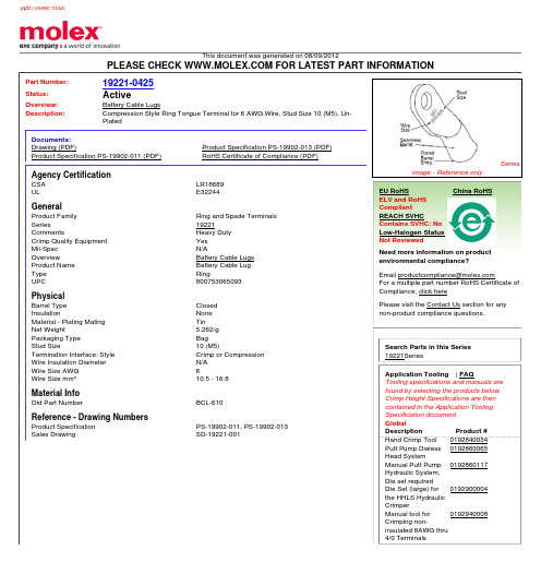
This document was generated on 08/09/2012PLEASE CHECK FOR LATEST PART INFORMATIONPart Number:19221-0425Status:ActiveOverview:Battery Cable LugsDescription:Compression Style Ring Tongue Terminal for 6 AWG Wire, Stud Size 10 (M5), Un-PlatedDocuments:Drawing (PDF)Product Specification PS-19902-013 (PDF)Product Specification PS-19902-011 (PDF)RoHS Certificate of Compliance (PDF)Agency CertificationCSA LR18689ULE32244GeneralProduct Family Ring and Spade Terminals Series19221CommentsHeavy Duty Crimp Quality Equipment Yes Mil-Spec N/AOverviewBattery Cable Lugs Product Name Battery Cable Lug Type RingUPC800753065093PhysicalBarrel Type Closed InsulationNone Material - Plating Mating Tin Net Weight5.262/g Packaging Type Bag Stud Size10 (M5)Termination Interface: Style Crimp or Compression Wire Insulation Diameter N/A Wire Size AWG 6Wire Size mm²10.5 - 16.8Material InfoOld Part NumberBCL-610Reference - Drawing NumbersProduct Specification PS-19902-011, PS-19902-013Sales DrawingSD-19221-001Seriesimage - Reference onlyEU RoHSChina RoHSELV and RoHS Compliant REACH SVHCContains SVHC: No Low-Halogen Status Not ReviewedNeed more information on product environmental compliance?Email productcompliance@For a multiple part number RoHS Certificate of Compliance, click herePlease visit the Contact Us section for any non-product compliance questions.Search Parts in this Series 19221SeriesApplication Tooling | FAQTooling specifications and manuals are found by selecting the products below.Crimp Height Specifications are then contained in the Application Tooling Specification document.GlobalDescription Product #Hand Crimp Tool 0192840034Putt Pump Dieless Head System0192860065Manual Putt Pump Hydraulic System,Die set required 0192860117Die Set (large) for the HHLS Hydraulic Crimper0192900004Manual tool for Crimping non-insulated 8AWG thru 4/0 Terminals0192940008This document was generated on 08/09/2012PLEASE CHECK FOR LATEST PART INFORMATION分销商库存信息: MOLEX 0192210425。
1984222资料
PHOENIX CONTACT GmbH & Co. KG http://www.phoenixcontact.de
Page 3 / 3 Mar 9, 2008
Page 2 / 3 Mar 9, 2008
元器件交易网
PT 1,5/ 8-PVH-3,5-A Order No.: 1984222
http://eshop.phoenixcontact.de/phoenix/treeViewClick.do?UID=1984222
Address
Tools 1205037 SZS 0,4X2,5 Screwdriver, bladed, matches all screw terminal blocks up to 1.5 mm² connection cross section, blade: 0.4 x 2.5 mm
PHOENIX CONTACT GmbH & Co. KG http://www.phoenixcontract from the online catalog
PT 1,5/ 8-PVH-3,5-A
Order No.: 1984222
http://eshop.phoenixcontact.de/phoenix/treeViewClick.do?UID=1984222
Marking 0804073 SK 3,5/2,8:FORTL.ZAHLEN Marker card, printed horizontally, self-adhesive, 10-section marker strip, 14 identical decades marked 1-10, 11-20 etc. up to 91-100, sufficient for 140 terminal blocks
VIPER-22A资料及原理图要点

VIPER-22A资料及原理图(六祖故乡人编) VIPER-22A中文资料:V IPER22A芯片概述:意法半导体的V IPER22A芯片为专用开关电源集成电路。
其内部结构如图1所示。
芯片工作时, 直流电压从漏极脚进入集成电路, 经整流和稳压后供给开关电源工作, 从而使这个电路工作时不需要外接启动电阻。
即使VDD供电电路不正常, 电源电路的振荡电路仍能起振, 而且上图1 V IPER22A芯片内部结构电路有输出电压。
在VDD正常前, 由芯片内部自身供电, 经过很短时间后, VDD供电电源正常, 此时,利用门电路控制开关电路(ON /OFF)断开从栅极输入的供电回路。
V IPER22A 有过热、过压保护功能。
VDD从4脚输入后, 首先送入比较器, 一旦输入VDD ≥42 V, 则触发器( FF1)输出一个置位信号1使控制振荡电路工作的触发器( FF2)输出为0,锁住U2 , 振荡信号无法输出, 即开关管不工作。
当输入电压小于1415 V时, U3 也将输出一个复位脉冲, 使开关管不工作。
当电路过热时, R1 为1,将FF2置0, 开关管不工作。
当供电电压VDD在正常范围时, FB所得的取样电压与基准电压0123 V相比较, 用其比较结果去控制FF2 的转换频率,从而控制开关管的状态转换, 实现控制输出电压,达稳压的功能。
该集成电路芯片内部包含60kHz的振荡电路, 其外围电路相当简单。
3 V IPER22A开关电源电路本文所使用的V IPER22A芯片具有优良的控制功能, 使得外围电路的设计较简单, 只需考虑一般的短路、过载电路保护即可。
电路原理图如图2。
图2 电路原理图(下图)在交流电源的输入端接电容C0 用于滤除低频差模噪声, 接扼流圈用于过滤掉电网上的干扰, 同时也滤掉电源对电网的干扰。
220 V的交流电源输入后,经四个二极管构成的桥式整流电路整流, C1 滤波后输出一个300 V左右的直流信号。
中文新闻信息分类及代码编制原则
前言随着信息技术的不断发展和应用,人类社会已进入信息化时代。
信息化社会的重要标志是信息处理标准化、信息存储数字化和信息发布网络化。
中文新闻信息作为社会信息的重要组成部分,迫切需要通过标准化进行规范,从而降低成本,实现新闻行业之间、新闻行业和广大用户之间的新闻信息交换、存储、处理和共享。
《中文新闻信息分类》(以下简称《分类》)的制订,是为了实现中文新闻信息分类体系的规范化、标准化,进一步开发和整合中文新闻信息资源。
同时,也是为实现中文新闻信息分类自动化打下一个可靠的基础。
由于传统的手工分类周期长、费用高、效率低,而且需要具有专业知识的人员才能胜任,所以难以满足信息成指数增长的今天的实际需要,实现分类自动化是中文新闻信息分类工作的必由之路。
《分类》是在分析研究国际、国内众多新闻媒体已有的分类方法、规则,总结国内主要传媒机构新闻信息分类的多年实践经验,以及对有关新闻信息分类理论探讨的基础上制订的。
《分类》是以GB 7027-1986《信息分类编码的基本原则和方法》为依据,借鉴和吸收《中国图书资料分类法》、《中国档案分类法》,以及国外一些比较成熟的分类法中适合中文新闻信息特点的成分,从中文新闻信息的实际出发制订的。
《分类》的附录A、附录B、附录C、附录D和附录E均为规范性附录。
《分类》由×××联合提出。
《分类》由×××归口。
《分类》起草单位:《分类》主要起草人:《中文新闻信息分类标准》编制原则1 范围《分类》规定了中文新闻信息分类体系和分类代码。
《分类》规定了中文新闻信息分类方法的一般原则。
《分类》适用于通讯社(新闻社)、报社、期刊社、广播电台、电视台、网络媒体,以及各种资讯机构对中文新闻信息进行分类标引和编制分类目录。
2 规范性引用文件《分类》采用下列国家标准,其随后所有的修改或最新版本适用于本《分类》。
GB/T 2659-2000 《世界各国和地区名称代码》GB/T 2260-2002 《中华人民共和国行政区划代码》GB 3304-91 《中国各民族名称的罗马字母拼写法和代码》3 术语和定义《分类》采用下列定义。
- 1、下载文档前请自行甄别文档内容的完整性,平台不提供额外的编辑、内容补充、找答案等附加服务。
- 2、"仅部分预览"的文档,不可在线预览部分如存在完整性等问题,可反馈申请退款(可完整预览的文档不适用该条件!)。
- 3、如文档侵犯您的权益,请联系客服反馈,我们会尽快为您处理(人工客服工作时间:9:00-18:30)。
Specifications
CHARACTERISTIC Frequency (MHz) Output Power (dBm) Variation Over Temperature (dBm) Spurious (dBc) Phase Noise (dB) TYPICAL Ta= 25 ºC 1200 +10 +0.75 -70 -88 dBc/Hz @ 100 Hz -117 dBc/Hz @ 1 kHz -125 dBc/Hz @ 10 kHz -123 dBc/Hz @ 30 kHz -135 dBc/Hz @ 100 kHz -146 dBc/Hz @ 1 MHz 1.5 -25 TTL (High=Locked) +1 -55 ºC 15 150 2.0 -20 TTL (Low=Unlocked) +15 +125 ºC 15 160 MIN/MAX Ta = -20 ºC to +70 ºC 1200 +9 +1 -60
VSWR Harmonics (dBc) Lock Indicator Stability (ppm) Storage Temperature Supply Power DC mA
Spectrum Microwave, Inc.
2707 Black Lake Place Phila, Pa. 19154 PH: 215-464-4000 FAX: 215-464-4001
元器件交易网
PHASE LOCKED OSCILLATOR MODEL 611222 (1200 MHz)
Features
! Low Phase Noise: -135 dBc/Hz @ 100 kHz ! Low Spurious: -70 dBc Typical ! Internal Reference Design ! Environmental Screening Available
Rev. 9/22/08
元器件交易网
PHASE LOCKED OSCILLATOR MODEL 611222 (1200 MHz)
Outline Drawing
Spectrum Micr Lake Place Phila, Pa. 19154 PH: 215-464-4000 FAX: 215-464-4001
Description
Spectrum Microwave’s Series 600 Phase Locked Oscillators use a High “Q” Coaxial Resonator in the resonant circuit. The circuit is lightly loaded to obtain the lowest phase noise possible. The resonator is soldered to a printed circuit board and well grounded to minimize modulation sidebands during shock and vibration. Buffer amplifiers are used to provide isolation from load VSWRs; Regulators filter noise on the DC input voltage. External reference models are also available. A lock indicator circuit is provided to signal an out-of-lock condition.
