LS-103A视频抗干扰器安装使用说明书
视频抗干扰器说明2010122210124982
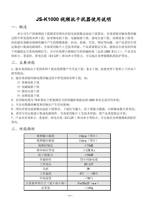
JS-K1000视频抗干扰器使用说明一、概述本公司生产的视频抗干扰器采用国内首创交流指数动态抗干扰算法,有效消除同轴电缆传输过程中所受到的各种干扰,如变频电机干扰、电磁辐射干扰、强电台波干扰、高频设备干扰等,因此能有效解决视频传输中产生的图像叠影、抖动、扭曲、雪花、网纹等问题。
该产品采用专用定做进口集成电路制作,全部采用贴片工艺技术焊接,产品质量稳定可靠,能保证在恶劣的环境下传输稳定可靠的视频信号,并可有效增大视频信号的传输距离(达到1000米以上),产品具有体积小、重量轻、供电压低(DC12V)和功率小等特点,可安装在各种摄像机的防护罩内。
二、主要功能1、能有效消除由于受到各种干扰而使图像产生雪花干扰、条文干扰、扭曲变型干扰和上下抖动干扰等情况;2、能有效消除同轴电缆传输过程中所受到的各种干扰;如:⑴变频电机干扰⑵电磁辐射干扰⑶强电台波干扰⑷高频设备干扰3、在同轴电缆为75-5情况下把视频信号的传输距离提高到1000米而无需任何补偿;4、不会对图像清晰度和信噪比产生任何影响;5、国内首创交流指数动态抗干扰算法,干扰信号越大、抗干扰能力越强,以指数函数关系变化;6、采用专用定做进口集成电路制作,全部采用贴片工艺技术焊接,使产品质量稳定可靠;7、产品具有体积小、重量轻、供电压低(DC12V)和功率小等特点,可安装在各种摄像机的防护罩内。
三、性能指标视频输入幅值1Vp-p(75Ω)视频输出幅值1Vp-p(75Ω)视频信噪比≥70dB频率响应带宽≥12MHz抗干扰能力≥30dB传输特性75Ω同轴电缆工作电压DC-12V功耗3W工作温度-5℃-+50℃环境湿度<90%主设备外形尺寸(宽×高×深)54x38x25(mm)总重量<100g-1-四、安装方法及系统连接图1、安装方法及步骤:⑴切断要安装视频抗干扰器同轴电缆两端设备的电源;⑵将视频抗干扰器主设备(A端)连接在视频信号的输出设备的输出端;⑶将视频抗干扰器适配器(B端)连接在该视频信号的输入设备的输入端;⑷将视频信号传输的同轴电缆两端分别连接在视频抗干扰器主设备、适配器两端;⑸开启视频抗干扰器及系统电源。
SK-103A说明书
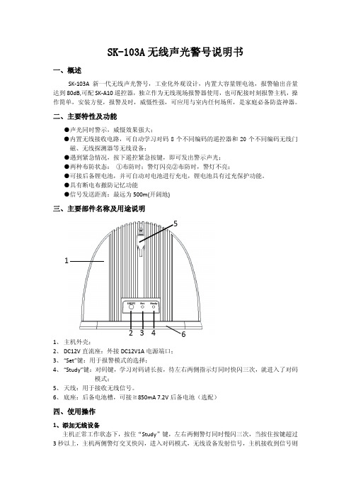
SK-103A 无线声光警号说明书一、概述SK ‐103A 新一代无线声光警号,工业化外观设计,内置大容量锂电池,报警输出音量达到80dB,可配SK ‐A10遥控器,独立作为无线现场报警器使用,也可配接时刻报警主机,操作简单,安装方便,报警及时,威慑性强,可应用与室内任何场所,是家庭必备防盗神器。
二、主要特性及功能●声光同时警示,威慑效果强大;●内置无线接收电路,可自动学习对码8个不同编码的遥控器和20个不同编码无线门磁、无线探测器等无线设备;●遇到紧急情况,按下遥控紧急按键,即可发出警示声光;●两种布防状态: ①布防时;警灯闪亮②布防时,警灯不亮;●可接后备锂电池,并可自动对电池进行充电,锂电池具有过充保护功能。
●具有断电布撤防记忆功能●信号发送距离:最远为500m(开阔地)三、主要部件名称及用途说明1、 主机外壳;2、 DC12V 直流座:外接DC12V1A 电源端口;3、 “Set”键:用于报警模式的选择;4、 “Study”键:对码键,学习对码请长按,待左右两侧指示灯同时快闪三次,就进入了对码 模式;5、 天线:用于接收无线信号。
6、 底座:后备电池槽,可接≧850mA 7.2V 后备电池(选配)四、使用操作1、添加无线设备主机正常工作状态下,按住“Study ”键,左右两侧警灯同时慢闪三次,当按住按键超过3秒以上,主机两侧警灯交叉快闪,进入对码模式,无线设备发射信号,主机接收到信号则1 3 456警号发出“滴‐滴”一声,表示无线设备添加成功,松开“study”键,主机发出“滴‐滴”两声,主机退出对码模式。
当添加设备数量超过主机允许设备数量,则主机提示需要清空操作(两侧警灯交叉慢闪三次);清除操作后,所有无线设备全部清空。
2、删除无线设备按住“Study”键,两侧的警灯同时慢闪三次,当按住按键超过3秒以上,主机两侧警灯交叉快闪,不松开“Study”键情况下,再同时按一下“Set”键,两侧警灯熄灭,表示清除完成。
电抗屏蔽器操作指南

电抗屏蔽器操作指南电抗屏蔽器是一种用于降低电磁干扰的重要设备。
它主要用于工业设备、电力系统和通信系统中,用于过滤掉或减小电磁干扰对设备正常工作的影响。
在正确操作电抗屏蔽器之前,我们需要了解它的工作原理和正确使用方法。
电抗屏蔽器的工作原理是利用电磁感应的原理,通过引入一个具有特定电感和电阻的电路来衰减电磁信号。
通过这种设计,它可以将不需要的电磁信号引导到地线或其他负载上,从而保证设备的正常运行。
以下是关于电抗屏蔽器的操作指南与注意事项。
1. 设置正确的电抗屏蔽器参数在使用电抗屏蔽器之前,首先要正确设置其参数。
这些参数将根据具体的工作环境和设备要求来确定。
常见的参数包括电感值、电容值和电流容量等。
确保根据标准或设备制造商提供的指南设置正确的参数。
2. 安装位置的选择电抗屏蔽器的位置选择非常重要。
它应该放置在电源线进入设备或电路的地方,以便降低电磁干扰的传播。
此外,也要注意避开热源和其他可能对设备产生干扰的元件。
正确的安装位置可以最大限度地提高电抗屏蔽器的效果。
3. 保持设备清洁确保经常清洁电抗屏蔽器以保持其良好的工作状态。
由于电抗屏蔽器通常安装在设备内部,它容易受到灰尘和其他污染物的影响。
定期检查并清除它们可以确保设备的持续正常运行。
4. 定期维护和检查定期进行维护和检查是确保电抗屏蔽器工作正常的关键。
这包括检查电缆连接是否松动、是否存在损坏以及设备是否受到其他物理损伤等。
如果发现任何问题,应及时采取措施修复或更换。
5. 防止过载电抗屏蔽器也有其电流容量限制,不要超过其额定电流。
过载可能导致电抗屏蔽器发热、损坏甚至引发火灾。
因此,确保设备不超过其额定电流是非常重要的。
6. 正确配置多个层级的电抗屏蔽器在某些较大的设备或系统中,可能需要多级电抗屏蔽器来提供更好的过滤效果。
在这种情况下,要正确配置电抗屏蔽器的各个层次,以确保干扰信号得到有效地过滤和屏蔽。
7. 培训操作人员为了确保电抗屏蔽器的正确使用,培训操作人员是很重要的。
阿斯卡103APO使用说明书

103 APO使用说明书User s Manual,欢迎使用ASKAR 103APO 中文版(简体)E n g l i s h使用产品前请仔细阅读本使用说明书。
产品尺寸及部件图S t e p s o f D e t a c h i n g t h e E x t e n d e r T u b eI n s t r u c t i o n s f o r u s e警告w w w.s.m103 APOUser s Manual,w w w.s.mAskar 103APO是一款拥有103mm口径,700mm焦距,原生焦比f/6.8的天文望远镜。
Askar 103APO的镜片结构秉持了锐星光学的APO镜片传统,为三片式APO全分离镜头设计,其中含有一片ED玻璃。
Askar 103APO镜筒全部使用高质量CNC加工工艺,经过阳极氧化和表面喷漆处理。
主镜筒内置光阑,且内壁全部进行消光处理,有效减少杂散光对成像的影响,此外,遮光罩使用可伸缩设计,并配有加大的遮光罩手拧锁紧螺丝,防止遮光罩在使用过程中滑落。
在Askar 103APO的调焦器上,共设有2组寻星镜基座,分布在调焦器的两侧。
除了在更换寻星镜位置时无需拆装,还能提供更多位置接驳天文配件。
Askar 103APO 抱箍的轻量化设计,使其整体重量仅750g。
提手的多功能设计,使其同样可以接驳需要使用寻星镜基座的天文配件。
抱箍使用C N C 定制手拧螺丝搭配蚌壳式开口设计,无需多余工具,可直接拆装。
鸠尾板规格为Vixen型,可搭配同规格赤道仪或经纬仪,鸠尾板多孔的设计,便于调整鸠尾板相对抱箍的位置,其长度达到290m m ,在使用时更方便配平。
Askar 103APO 采用分段式主镜筒设计,在不使用延长管时,可搭配专用0.6倍减焦镜或可搭配双目目镜使用。
装配延长管后,即可使用0.8倍减焦镜或1.0平场镜,或连接天顶搭配目镜观测天体。
在调焦器选择上,Askar 103APO 采用了双速齿轮齿条式3.3英寸刚性调焦器,CNC高精度加工,兼容大部分电动调焦设备,提供100mm调焦行程,并搭载高精度重型构图旋转器,采用激光雕刻长度方向与圆周方向的S p e c i f i c a t i o nAperture size: 103mm Focal length: 700mm Focal ratio: f/6.8Objective lens: Triplet air-spaced APO (including one ED glass) Total length: 600mm (when the dew shield is contracted) 711mm (when the dew shield is stretched) Net weight: 4.75kg Gross weight: 5.5kgRear-end adapter: 2" adapter, 1.25" adapterStandard package items: a 103APO OTA, a pair of tube rings, a handle, an Askar 290mm Vixen dovetail plate, a manual,a transportation bagI t e m s i n 103A P O P a c k a g i n g说明书箱包一个103APO OTA, a pair of tube rings, a handle, a 290mm Vixen dovetail plateInstruction manual锁紧螺丝示意图包装含有The Locking Screw Position Diagram有效口径:103mm 焦距:700mm 焦比:f/6.8物镜类型:三片式全分离APO(包括一片ED玻璃)全长:600mm(遮光罩缩进状态)711mm(遮光罩伸出状态)本体重量:4.75kg 标准装重量:5.5kg末端接口:2英寸接口、1.25英寸接口标配:103APO本体一个,抱箍一对,提手一个,290mm Vixen 窄型鸠尾板一个,说明书一份,箱包一个标尺,便于用户调整和信息记录。
LS变频器说明书iS5-中文说明书
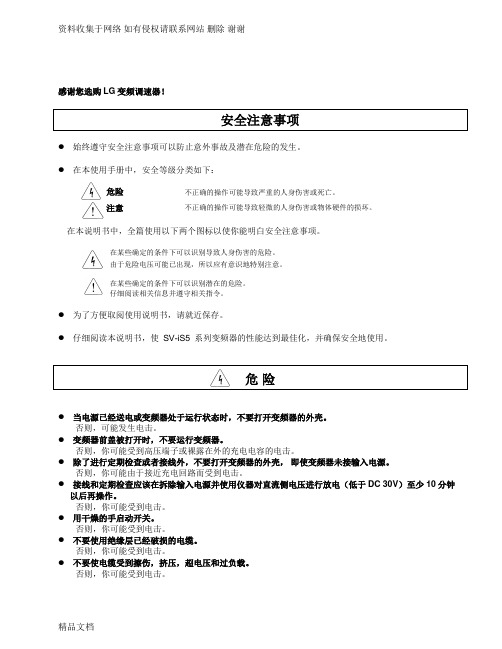
在某些确定的条件下可以识别导致人身伤害的危险。 由于危险电压可能已出现,所以应有意识地特别注意。
在某些确定的条件下可以识别潜在的危险。 仔细阅读相关信息并遵守相关指令。
为了方便取阅使用说明书,请就近保存。
仔细阅读本说明书,使 SV-iS5 系列变频器的性能达到最佳化,并确保安全地使用。
危险
当电源已经送电或变频器处于运行状态时,不要打开变频器的外壳。 否则,可能发生电击。
位,否则可能发生意外事故。
不要修改或变动变频器内部任何东西。 变频器的电子热保护功能可能无法保护电机。 在变频器的输入侧不要使用电磁式交流接触器作为变频器频繁启停的开关。 使用噪声滤波器来降低变频器产生的电磁干扰的影响,否则,附近的电子设备可能会受到干扰。 如果输入电压不平衡,需要安装交流电抗器。来自变频器的潜在高次谐波可能会引起电力电容器和发生
第一章 安装 .....................................................................................................................................10 1.1 检查 ..................................................................................................................................................... 10 1.2 环境条件 ............................................................................................................................................. 10 1.3 安装 ..................................................................................................................................................... 10 1.4 其它注意事项 ..................................................................................................................................... 11 1.5 尺寸 ..................................................................................................................................................... 12 1.6 基本配线 ............................................................................................................................................. 17 1.7 电源端子 ............................................................................................................................................. 18 1.7.1 类型 A 构造 ............................................................................................................................... 19 1.7.2 类型B 构造 ................................................................................................................................. 19 1.7.3 类型C 构造 ................................................................................................................................. 20 1.7.4 电源端子配线 ............................................................................................................................. 21 1.8 控制端子 ............................................................................................................................................. 23 1.8.1 控制端子配线 ............................................................................................................................. 24 1.8.2 键盘和 RS485电路连接配线 ..................................................................................................... 25
科力视觉 LS 系列激光雷达-避障型 使用说明书
LS 系列激光雷达-避障型使用说明书(2022年8月)(图片仅供参考,以实物为准)山东科力光电技术有限公司⏹指令和标准LS 系列激光雷达(简称LS)符合下列标准的要求 欧盟指令EMC指令2014/108/EC国际标准EMI:EN61326-1:2013EN55011:2009+A1:2010EMS:EN61326-1:2013EN61000-4-2:2009EN61000-4-3:2006+A1:2009+A2:2010EN61000-4-4:2004+A1:2010EN61000-4-6:2009EN61000-4-8:2010EN61000-4-11:2004GB标准GB 4028⏹安全注意事项以下安全警示标志,用以警告潜在的人身伤害危险,请务必遵从所有带有此标志的安全信息,以避免可能的伤害。
注意警告⏹安全使用注意事项注意在使用LS前,仔细阅读本说明书,了解安装、操作及设置的程⏹应用场合避障型LS 适用于移动机器人防碰撞,典型应用为自动导引运输车(AGV)和有轨穿梭小车(RGV)。
LS 的保护对象必须符合以下条件:1)仅对侵入保护区域内的物体进行保护。
2)LS 无法检测透明、半透明的物体。
3)侵入保护区域内的物体的尺寸必须大于等于LS 的检测能力。
请勿将LS 安装在下列类型的环境中:1)本说明书所规定的环境(温度、湿度、干涉光、冲击振动等)范围之外的地方。
2)有易燃、易爆性气体的地方。
3)有浓烟、微粒、腐蚀性化学剂等物质的地方。
4)可能会对LS 产生强光干扰(如直射光)的地方。
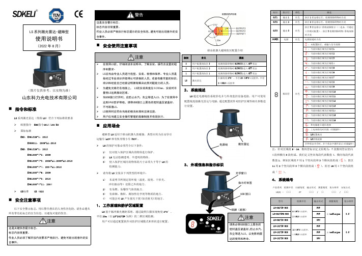
1、工作原理和防护区域配置LS 基于脉冲激光测距原理,通过旋转扫描实现角度270°、半径20m(以LS-2027BP 为例)的二维区域检测。
用户可以通过配置软件对防护区域模式和形状进行配置。
移动机器人避障防区配置介绍2、系统描述LS 通过电源线给系统供电并与外部监控设备连接。
用户可使用配置线连接激光雷达与电脑,通过配置软件对防护区域等相关参数进行设置。
视频抗干扰器的安装过程和注意事项

视频抗干扰器的安装过程和注意事项
视频抗干扰器的主要作用是抑制各种强烈电磁或电波信号(如电机、马达等大功率电机电器的启停)对视频信号的干扰,适用于当今视频监控的各个领域。
如何连接视频抗干扰器:
1.将发射器的视频输入端与摄像机的视频输出端用电缆或公对公的BNC转接头连接好
2.将传输电缆源端与发射器的射频输出端连接好
3.将摄像机和发射器上电
4.将传输电缆另一端与接收器的射频输入端连接好
5.将接收器的任意一个视频输出端口与DVR或者监视器连接好
6.将接收器上电,稍等片刻即可
在安装视频抗干扰器前请作如下检查:
线缆是否为系统要求的型号;
线缆接头与设备接口是否匹配;
线缆接头是够焊接牢靠,有无接触不良或短路的地方;
线缆本身是否有短路或短路;
设计传输线路,电源线与视频信号线的平行铺设不要过长。
视频抗干扰器要注意的问题
该设备需外供DC12V电源,请选择具有良好稳压、隔离功能、500mA以上的电源。
摄像机的视频输出与抗干扰器发射器的连接线不要长于1米,因为过长的线缆容易引入干扰,并造成清晰度下降。
该设备非防水设计,在潮湿环境下,请做好防水处理。
设备安装时,发射端和接收端之间的线缆应是完整的线缆,如线缆中需要加装设备,请安装在视频抗干扰器发射器之前或接收器之后,避免图像无法正常传输。
视频监控图像的清晰和稳定关系到安防工程的质量是否合乎要求,抗干扰器提供了在比较恶劣环境下的视频监控解决方案,给安防工程商带来极大的便利。
真实RMS Ampstik Plus抗干扰电流测量器操作手册说明书
Operators ManualTrue RMS Ampstik®Plus Slip-on AmmetersSensor LinkOperators ManualTrue RMS Ampstik ®PlusSlip-on AmmetersTable of ContentsPageSpecifi cations 2Safety Warnings 3Operating Instructions 4-5 Startup Test 4 RUN & HOLD Mode 4 Viewing the Measurement 5 Power Off 5Automatic Backlight 6Battery Replacement 7Cleaning7High Voltage Operation 7Troubleshooting 8Warranty 10Quality AssuranceBack CoverAvailable Stock Codes:8-020 XT PLUS 50HZ 8-020 XT PLUS 60HZ 8-020 XT PLUS EURO 8-020 XT PLUS FRG8-022 PLUS-50HZ 8-022 PLUS-60HZ 8-022 PLUS-EURO 8-024 PLUS-50HZ8-024 PLUS-60HZ8-024 PLUS-EUROOverviewThe True RMS Ampstik Plus has been developed specifi cally for mea s ure m ent of AC cur r ent in the electrical utility industry. The True RMS feature allows accurate mea s ure m ent of current even when the nominal waveform is distorted or when harmonics are present. This may be the case with Y connected transformer neutral leads and dis t ri b u t ion to many in d us t ri a l customers using SCR con t rol l ers and other switching de v ic e s. This in s tru m ent can be used re m ote l y with any hot stick and universal chuck adapter. The in s tru m ent has no moving parts and does not require clamping onto the wire. The molded housing is water resistant and will withstand high physical impact. The following specifi cations apply: SPECIFICATIONSModel Number8-020 XT Plus8-022 Plus8-024 PlusRange of OperationVoltage Phase to Phase0-500kV0-69kV0-400kVCurrent1-5000A1-2000A1-2000ASensor Opening Standard Wide Jaw Wide JawOpening Width 2.5 in6.35 cm 3.86 in9.8 cm3.86 in9.8 cmType of Reading Four readings Four readings Four readings ResolutionAmps 1-99.9A0.1A0.1A0.1AAmps 100-1999A1A1A1AAmps 2000-50000.01kA N/A N/AWeight 2.15 lbs,0.97 kg 3.8 lbs,1.76 kg3.8 lbs,1.76 kgAccuracy± 1%, ± 2 CountsFrequency Actual frequency indicated on unit50 Hz Calibrated47 to 53 Hz60 Hz Calibrated57 to 63 HzMechanicalOperating Temperature-22° to +140° F, -30° to +60° CLithium battery required for temperatures below -4° F (-20° C)Display 3.5 Digit displayBacklight Automatic ambient light sensorHousing Shock & water resistant molded urethaneHotstick Mounting Universal chuck adapter (hotstick not included)Battery9V Alkaline or LithiumEEC Standards Successfully passed international tests indicated by CEPage 2Page 3Safety Information• The True RMS Ampstik Plus is designed for use with a suitable universal hot stick. • All precautions appropriate for the line voltage should be taken. • The hot stick should be considered the sole voltage isolation device.• For safety purposes the face plate, battery cover, chuck, and entire Ampstik Plus should be considered to be at the same potential.•Putting the face plate, battery cover, chuck, or other parts of the Ampstik Plus within the air gap of adjacent phases or ground could cause a phase to phase orphase to ground fault.WARNING! Do not force the arms of the Ampstik PlusPage 4O perating Instructions The True RMS Ampstik Plus is controlled by a single push button switch located on the front panel. Operation is as follows:POWER ON - Press and release the control switch to turn on the instrument.Startup TestThe Ampstik Plus conducts a startup test to verify the sensors and circuitry is functioning correctly. The following screens will display during the test:If the test detects a failure, the display will show FAIL and a corresponding code. See page eight for the failure code chart.If the test determines the unit is functioning properly, it will move to normal mode and is ready to take the fi rst measurement. The display will show:RUN Option - The reading continuously changes as the current change s. The unit is immediately in the RUN mode after powering on. T o place the instrumentinto the RUN mode from a different mode, press and hold the control switch and scroll to the option RUN, then release the control switch to engage the option. To take measurements with the True RMS Ampstik Plus in the RUN mode, placethe conductor between the two arms and observe the display. For maximum accuracy, be sure that the conductor is below the notches on the arms. If the conductor cannot be placed below the notches, readings can be taken but the accuracy may be lessened.HOLD Option - Stores up to Four readingsPress and hold the control switch to scroll to the HLD option, and release the control switch to engage the option.The True RMS Ampstik Plus is now in the sample and hold mode, indicated by the word “HOLD” ap p ear i ng on the display. As shown below, nothing else will display until a measurement is held:To take the fi rst of the four measurements, place the conductor between the legs of the instrument. Remove the Ampstik Plus from the conductor. Repeat this- - -HOLDFAIL 10.065.51HOLD72.01 32 4HOLDNote: The display resolution changes on the following ranges:0-99.9Amps0.1Amp resolution100 to 1999 Amps 1Amp resolution2000 to 5000 Amps 2.00 kAmps10 Amp resolution (2 decimal places indicates kAmp range)XXXXXX.XX.XXCLEARING THE DISPLAY - Clearing the stored measurements You must fi rst go to the DEL option to clear the stored readings before takingfurther readings. Press and hold the control switch, the DEL option will appear: release the control switch. All of the data has been cleared. The data will also clear when either the OFF or RUN modes are selected. NOTE: If the instrument has four readings in its memory and another attemptis made to take a reading, the display will show: - - -POWER OFF - Turning the instrument OFFPress and hold the control switch to scroll to the OFF option. Release the control switch. The True RMS Ampstik Plus will turn itself off automatically after several minutes of inactivity.process to aquire up to three more readings. It holds the readings and displays them one at a time as follows:VIEWING THE STORED MEASUREMENTThe number of the reading that is being viewed will fl ash.To scroll to the next reading, press and release the control switch. Repeat this to scroll through all readings.Page 5Page 6BacklightThe Backlight on the Ampstik Plus is designed to automatically power on when the ambient light is low. This helps users view the display in low-light situations. The light sensor is located on the front of the unit. It's location is indicated with the light icon on the front panel next to the switch. The backlight will continue to power on automatically until the user manually changes the settings.POWER OFF BACKLIGHT - Manually power off the backlight Press the control switch until the following screen appears: After releasing the switch, the display will momentarily show:The backlight will stay off until the user manually powers it back on.POWER ON BACKLIGHT - Manually power on the backlight Press the control switch until the following screen appears: After releasing the switch, the display will momentarily show:The backlight will now automatically power on when light is diminished or untilthe user manually powers it back off.The user may see some fl icker with the backlight if the backlight is on when under artificial lighting. This is normal.B attery ReplacementWhen the “LO BAT” indication shows on the display, the battery should be re p laced. The unit will continue to operate for a few hours. The Ampstik is powered by a single 9V battery. To re p lace the battery, remove the four screws on the battery cover at the rear of the unit. Carefully insert a screwdriver blade in the notch and pry the cover out, being careful not to damage the cover seal. Pull the bat t ery out of the com p art m ent and sep a r ate the battery from the battery connector. To avoid breaking the battery leads do not pull on the battery only. Install a fresh battery and reinsert the battery in its com p art m ent. Reinstall the cover by gently press i ng it into place while pulling out on the edges of the com p art m ent, and reinstall the four cover screws. Take care to avoid over t ight e n i ng the screws. Always reuse the screws provided and do not damage or lose the o-ring seal on each screw.C leaningThe Ampstik can be cleaned by wiping with a small amount of alcohol on a rag.H igh Voltage OperationThis instrument is designed to operate in high voltage fi elds. How e v e r, diffi culty may be experienced when excessive corona to the instrument occurs. The unit may ex p e r i e nce over range and require power to be cycled or may lose a reading when in the sample and hold mode.Page 7Troubleshooting the Ampstik PlusUnit will not power onVerify there is a fresh 9V battery in the unit.Verifty the battery connectors have not been disconnected from the molded housing.Backlight FlickerDue to the refresh rate of the light, some users may see fl icker if the backlight is on when under artifi cial lighting. This is normal.Fail CodesFAIL CODE "1": Break to the main current sensorFAIL CODE "2": Break to a current sensor componentFAIL CODE "3": Circuit failureFAIL CODE "4": Circuit failureThe above fail codes may also trigger due to dirty pin connections causing errors in readings between the main board and molded housing assembly.The unit will not enter into measurement mode if the self-test has any of the above failures. The unit will need to be returned to SensorLink for repair evaluation. RepairSensorLink Service DepartmentPlease contact SensorLink directly for the return process of product for evaluation, repair, calibration, and verifi cation. Contact details:SensorLink CorporationTel: (360)595-1000Fax: (360)595-1001E-mail:*******************Page 8Page 9SensorLink Corporation W arrantySensorLink warrants each instrument it man u f ac t ures to be free from defects in materials and workmanship under normal use and service for the period of one year after date of shipment. Within this period, SensorLink agrees to repair or replace, at SensorLink’s option, any instrument that fails to perform as specifi ed. This Warranty shall not apply to any instrument that has been:1 Repaired, worked on, or altered, including removal of the front panel, by personsun a u t ho r ized by SensorLink in such a manner as to injure, in SensorLink’s sole judgment, the per f or m ance, sta b il i t y, or reliability of the instrument;j ect e d to misuse, negligence, or accident; or2 Sub3 Connected, installed, adjusted, or used otherwise than in ac c or d ance with theinstructions furnished by SensorLink.This Warranty is in lieu of any other warranty, expressed or implied. SensorLink reserves the right to make any changes in the design or construction of its in s tru m ents at any time, without incurring any obligation to make any change what e v e r in units previously de l iv e red.If a failure occurs, contact the manufacturer for a Return Au t ho r i z a t ion and instructions for return shipment. This warranty con s ti t utes the full understanding of the man u f ac t ur e r and buyer, and no terms, conditions, understanding, or agree m ent purporting to modify or vary the terms hereof shall be binding unless here a f t er made in writing and signed by an authorized offi cial of SensorLink.Page 10Q uality Assurance Certifi cationTrue RMS Ammeter Models8-020 XT Plus, 8-022 Plus, 8-024 Plus SensorLink certifi es that its calibration measurements are trace a ble to the National Institute of Standards and Tech n ol o g y (NIST), to the extent allowed by the Institute's cal i b ra t ion fa c il i t y, and to the calibration facilities of other In t er n a t ion a l Standards Or g a n i z a t ion members.This document certifi es the following True RMS Ammeter was tested at the SensorLink High Voltage Laboratory, Ferndale, WA, USA to the appropriate standard and comply with the requirements of that standard.Serial Numbers_____________________________________________________Model Numbers_____________________________________________________I hereby certify that the True RMS Ammeter listed above has passed all tests defi ned in the SensorLink standard. I also certify that I have reviewed the standard and test procedure and that they are suffi cient in determining compliance with the standard.Signed_______________________________________________Date_________________________________________________Sensor Link Corporation1360 Stonegate WayFerndale, WA 98248 USAphone: 360/595.1000fax: 360/595.1001 Form No: SALE-Manual Template AMPSTIK-006 REV: V01Date: 11/19/2013Manual Stock Code No: M050-010-002。
RS103辐射抗干扰自动测试系统集成适配及辅助装置

RS103辐射抗干扰自动测试系统集成适配及辅助装置一、功能概述GJB 151-1997 RS103辐射抗干扰自动测试系统覆盖的频率范围为10kHz~18GHz,该系统分三个电场敏感度子系统(10kHz~100MHz 系统,100MHz~1GHz系统, 1 ~18GHz系统)。
自动测试系统需实现以下功能:●集成功率放大器、天线、微波功率计、定向耦合器等组成EMC测试系统,主要仪器见附表1 。
●为减小功率损耗,1 ~18GHz系统必须放在全电波暗室内,仪器安装在机柜内,天线安装在支架上,三个此频段的天线同时安装在天线支架上,需要自动程控切换,机柜和支架固定在四轮推车上。
●低频仪器放在屏蔽室内,仪器安装在机柜内,不需要自动切换。
●由于频段和功率不同,需要切换不同的功率放大器和天线。
●控制计算机要远离微波仪器,置于全电波暗室和屏蔽室外。
●系统软件除实现所有设备的远程控制外,须满足GJB151A和IEC61000-4-3标准的场地校验及测试功能。
附表1 主要仪器清单二、系统组成:1、软件;3、辅助装置;A.探头上下移动架;(1套)根据系统配置的三个大小规格不同的探头,设计于一体,使之上下移动操作灵活准确方便,要求如下;1,探头上下移动距离1300mm。
2,大探头气动90度定位旋转。
3,电动控制上下移动。
4,非金属结构。
B.万向移动车;(1辆)将探头上下移动架以及相应组件安装于一体,方便移动操作,要求如下;1,车载重量大于200Kg。
2,移动灵活并带有定位装置。
3,金属结构。
C.单元柜;(2套)将系统各单元分类组装,要求如下;1,规格;按系统单元分件尺寸设计。
2,金属结构。
3,表面喷涂处理。
三、验收、服务及保修软硬件及系统集成需达到使用方的预期要求,全部完成后方能验收,必须满足GJB151A和IEC61000-4-3标准的场地校验及测试功能。
技术支持:一般故障24小时内响应保修年限:电子设备保修3年四、系统场地布置图四、美国AR 公司原装机架(单天线)(参考)1 ~18GHz系统五、100MHz~18GHz原理图。
(349)抗干扰设备操作规程

脉冲频率调节
冲相选择
冲相选择
EUT.ON 键ቤተ መጻሕፍቲ ባይዱ
冲电压极性
测试 结束 五、注意事项:
1.开机和关机之前均要将电压设定旋钮(AMPLITUDE)逆时针旋转到底。 2.非专业人员请勿进行设置,具体设置请参照仪器说明书。 编制:林思宙 审核:侯振兴 批准:吕全彬 发布日期:2011-3-16
文件标题 中山市美斯特实业有限公司
编 版 页
号 次 码
Q/MST-108-0011-2011 A/1 1/1
抗干扰设备操作规程
一.适用范围及技术参数 适用于 NS61000-4K 型群脉冲发生器。 二.操作规程 电源
1、在仪器后面板的 AC IN 输入口接上仪器的工作电源,LINE IN 输入口接 被试设备的工作电源。 1、SG 脉冲接地端与参考接地板连接,L、N、PE 电源输出端供被试设备工 作,分别为火线、零线和地线。 1、对定时器(TIMER)进行实验时间设定,范围为 0.1 秒~999 小时。当 设置为 0 时表示无穷大,第一位为模式设置,设置为 F,最后一位为 时间单位。 1、逆时针旋转电压设定旋钮(AMPLITUDE)到底。
接线
时间设置
电压设定 开机 脉冲电压调节
1、向上按电源开关(POWER)使本机工作。 1、调节电压设定旋钮(AMPLITUDE)设置脉冲峰值,单位为 kV,电压表左 边第一位显示极性。 1、按频率选择功能键,F1 为脉冲频率 2.5kHz;F2 为脉冲频率 5 kHz;F3 为脉冲频率 100 kHz。 1、 选择群脉冲迭加到某个端口。按 L 则脉冲迭加到火线; 2、 按 N 则脉冲迭加到零线;按 PE 则脉冲迭加到地线。 1、 选择群脉冲迭加到某个端口。按 L 则脉冲迭加到火线; 2、 按 N 则脉冲迭加到零线;按 PE 则脉冲迭加到地线。 1、 按 EUT.ON 键接通被试设备的工作电源,同时黄色指示灯亮, 2、 再按一下则断开被试设备的工作电源,同时黄色指示灯灭。 1、冲电压极性选择键, “+”键按下表示脉冲输出为正极性; “-”键按下 表示脉冲输出为负极性。 1、 按 RUN 键,脉冲按设定的参数开始输出,测试开始, 2、 按 STOP 键则停止输出脉冲。 1、使用完毕,逆时针旋转电压设定旋钮(AMPLITUDE)到底,再关电源。
视频抗干扰器(C400V)使用说明书

警告1)用户使用之前,请认真阅读用户手册,不要擅自打开机箱,以防电击。
2)设备不得在高温、高湿度的环境下使用。
3)不得接触腐蚀性比较强的物体,不得用液体清洗设备。
4)应在电压相对稳定的状况下使用,以免造成设备意外损坏。
5)避免设备遭到强烈的撞击和震动。
!打开包装箱后,请按照“出厂配置”进行核对,如有问题请致电您的供应商。
感谢您采用本公司生产的产品。
本产品是采用视频放大方式,将视频信号进行全频带放大,然后在接收端恢复的方法达到延长传输距离的目的。
在箱体设计上采用金属材料,增加了设备的抗震性,安装方便;在信号传输上,提高了发送端输出信号的幅度,经过接收端对不同频率信号的补偿,提高了传输信噪比,还原由于线缆长距离传输对不同频率信号造成的损耗。
增强了抗干扰性,提高了图像清晰度。
产品特点与功能描述:(C400V)是本公司研制的一种专用于视频信号的抗干扰器.。
体积小巧,安装方便,工作电流低,视频还原度高等特色,受到广大用户好评。
在安装调试之前,请认真阅读本使用说明书。
1)抗干扰能力强,采用先进的编码技术,可有效抵抗火花干扰、50HZ交流干扰、无线电等干扰信号;适用于电梯、工厂、道路、变电站等干扰信号较多、较强场所的视频信号传输。
2)对长距离视频传输有着良好的补偿作用3)故障率低,可连续24小时工作,采用模块化、高集成设计,满足顾客高稳定、高效益的要求。
4)清晰度高,水平分辨率可达480线以上,色彩鲜艳无重影。
5)适用线缆类型多,视频线、射频线等75Ω同轴线缆;建议采用视频线缆(SYV75)传输信号,设备可发挥出更好的远距离传输功能。
设备接口说明:设备安装简图:常见故障及排除方法:C400V发端技术参数:1。
FM 无线抗静音抗干扰天线安装指南说明书
SUB- FRONT FRONT
WOOFER RIGHT
LEFT
L
R HDMI OUT
~ MAINS
FM/MW ANTENNA MW
FM 75
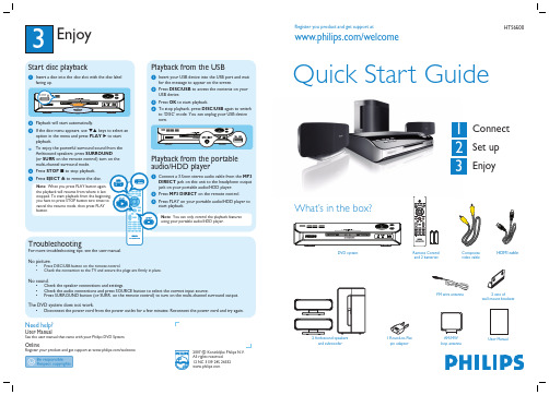
DVD system (rear)
Ensure that this portion is fully inserted in to the jack.
2 Set up
User Manual
1 Connect
A Placement
Proper speakers system placement is important to ensure optimum sound performance.
C Connect the Ambisound speakers
and subwoofer
option in the menu and press PLAY X to start playback. z To enjoy the powerful surround sound from the Ambisound speakers, press SURROUND (or SURR on the remote control) turn on the multi-channel surround mode. D Press STOP x to stop playback. E Press EJECT Z to remove the disc.
system (optional)
To hear the TV audio through this home theater system, use the red and white audio cables (not supplied) to connect the TV IN (R/L) jacks on this DVD system to the AUDIO output jacks on your TV.
- 1、下载文档前请自行甄别文档内容的完整性,平台不提供额外的编辑、内容补充、找答案等附加服务。
- 2、"仅部分预览"的文档,不可在线预览部分如存在完整性等问题,可反馈申请退款(可完整预览的文档不适用该条件!)。
- 3、如文档侵犯您的权益,请联系客服反馈,我们会尽快为您处理(人工客服工作时间:9:00-18:30)。
LS-103A视频抗干扰器安装使用说明书
Non-Interference with image Manual
一、产品应用范围:(Product Apply To:)
本产品主要适用于电梯、医院、路口、厂区等各种环境,防止监视視頻传输过程中受到各种强烈电磁信号及电波信号(如电机、马达等大功率的瞬间启动电流干扰等)对視頻信号的干扰。
This kind of product applies to elevators、hospitals、an intersection、factories etc. , avoiding any interference to the process of monitoring the image from any kind of furious electromagnetic signal and electric waves signal.
使用本产品能有效抑制干扰,解决視頻影像抖动、扭曲、斜波纹等问题。
确保視頻讯号于恶劣环境中的传输品质稳定,并可增长視頻传输距离。
When you using this kind of product , you can restrain the interference effectively and you can solve the problems about the jiggle、the swirl、the ripple with the images. To ensure the stability of the signals’ transmitting quality in the bad environment , and increasing the distance of the images transmitting.
二、产品使用参数及注意事项:(Product Use Parameters and Attention Matters)
.发射机额定工作电压为DC12 V,接收机无需使用工作电源,只要正确接好线即可正常工作。
(Transmitter running voltage is rated at DC12 V, receiver don’t need working power, it will work normally if right connect the wire )
.視頻接收端的4档亮度调节开关是用来调整图像亮度、对比度及清晰度的,调整方式有4x4=16种组合方式。
(Video receiving end of the four stalls brightness adjustment switch is used to adjust image brightness, contrast and definition, adjusting style contain 4x4 = 16 kinds of combinations)
本产品出厂亮度调节开关的参数打在第2档的位置,您也可依现场实际状况自行调整。
(This product factory brightness adjustment parameters of a switch in the No. 2 stall position, you also can enjoy the scene actual situation of self-correction)
三、产品使用接线图:(Product Use Wiring Diagram)。
