st16规格书v021
上海海栎创微电子有限公司 CST816S 自电容触控芯片数据手册说明书

上海海栎创微电子有限公司CST816S数据手册高性能自电容触控芯片Rev:V1.2 概述CST816S自电容触控芯片,采用高速MCU内核并内嵌DSP电路,结合自身的快速自电容感应技术,可广泛支持三角形在内的多种自电容图案,在其上实现单点手势和真实两点操作,实现极高灵敏度和极低待机功耗。
芯片特点◆内置快速自电容检测电路及高性能DSP模块✧支持在线编程;✧内置看门狗;✧多个按键支持;✧支持待机手势唤醒功能;◆电容屏支持✧最多支持13个感应通道;✧通道悬空/下拉设计支持;✧模组参数自动调校;◆性能指标✧刷新率>100Hz;✧单点手势和真实两点操作;✧动态模式下典型功耗<2.5mA;✧待机模式下典型功耗<10uA;✧休眠模式下典型功耗<5uA;◆通讯接口✧I2C主/从通讯接口,速率10Khz~400Khz可配置;✧兼容1.8V/3.3V接口电平。
◆电源供电✧单电源供电2.7V~3.6V,电源纹波<=50mv;◆封装类型:QFN203mm*3mm*0.4mm;1.CMOD0/CMOD1必须接稳压电容,大小在1nF~5.6nF;功能描述CST816S自电容触控芯片,通过其内置的快速自电容感应模块,可无需任何外接器件(电路旁路电容除外),即可在三角形等图案上实现单点手势和真实两点功能;在实现快速反应的同时,具有极其优异的抗噪、防水、低功耗表现。
工作模式动态模式当频繁有触摸操作时,处于此模式;在此模式下,触控芯片快速对触摸屏进行自电容扫描,以及时检测触摸并上报给主机。
在没有触摸2S后,自动进入待机模式。
自动进入待机模式的功能可以通过寄存器进行控制。
待机模式在此模式下,触控芯片以较低频率对触摸屏进行扫描,检测到手指触摸后进入动态模式,同时通过IRQ 引脚唤醒主机;也可通过复位引脚切换到动态模式。
休眠模式当接收到睡眠命令后,处于此模式;在此模式下,触控芯片处于深度睡眠状态,以最大限度节省功耗,可通过复位引脚切换到动态模式。
ST STP16NF06 STP16NF06FP 数据手册

1/9April 2002.STP16NF06STP16NF06FPN-CHANNEL 60V - 0.08 Ω - 16A TO-220/TO-220FPSTripFET™ II POWER MOSFETs TYPICAL R DS (on) = 0.08Ωs EXCEPTIONAL dv/dt CAPABILITY s LOW GATE CHARGE AT 100 o C sAPPLICATION ORIENTED CHARACTERIZATIONDESCRIPTIONThis Power MOSFET is the latest development of STMicroelectronis unique "Single Feature Size™"strip-based process. The resulting transistor shows extremely high packing density for low on-resistance, rugged avalanche characteristics and less critical alignment steps therefore a remarkable manufacturing reproducibility.APPLICATIONSs MOTOR CONTROL, AUDIO AMPLIFIERS s HIGH CURRENT, HIGH SWITCHING SPEED s SOLENOID AND RELAY DRIVERS s DC-DC & DC-AC CONVERTERS s AUTOMOTIVE ENVIRONMENTTYPE V DSS R DS(on)I D STP16NF06STP60NF06FP60 V 60 V<0.1 Ω<0.1 Ω16 A 11 AABSOLUTE MAXIMUM RATINGS(•) Pulse width limited by safe operating area.(*) Current Limited by package’s thermal resistance (1)I SD ≤ 16A, di/dt ≤ 200A/µs, V DD ≤ V (BR)DSS , T j ≤ T JMAX.(2) Starting T j = 25 o C, I D = 8A, V DD = 30VSymbol ParameterValueUnitSTP16NF06STP16NF06FPV DS Drain-source Voltage (V GS = 0)60V V DGR Drain-gate Voltage (R GS = 20 k Ω)60V V GS Gate- source Voltage± 20V I D Drain Current (continuous) at T C = 25°C 1611(*)A I D Drain Current (continuous) at T C = 100°C 117.5(*)A I DM (•)Drain Current (pulsed)6444(*)A P tot Total Dissipation at T C = 25°C 4525W Derating Factor0.30.17W/°C dv/dt (1)Peak Diode Recovery voltage slope 20V/ns E AS (2)Single Pulse Avalanche Energy 130mJ V ISO Insulation Withstand Voltage (DC)--------2500V T stg Storage Temperature-55 to 175°C T jOperating Junction Temperature查询STP16NF06供应商STP16NF06/FP2/9THERMAL DATAELECTRICAL CHARACTERISTICS (T case = 25 °C unless otherwise specified)OFFON (*)DYNAMICTO-220TO-220FPRthj-case Thermal Resistance Junction-caseMax 3.336°C/W Rthj-ambT lThermal Resistance Junction-ambientMaximum Lead Temperature For Soldering PurposeMax62.5300°C/W °CSymbol ParameterTest ConditionsMin.Typ.Max.Unit V (BR)DSS Drain-sourceBreakdown Voltage I D = 250 µA, V GS = 060V I DSS Zero Gate VoltageDrain Current (V GS = 0)V DS = Max RatingV DS = Max Rating T C = 125°C 110µA µA I GSSGate-body Leakage Current (V DS = 0)V GS = ± 20 V±100nASymbol ParameterTest ConditionsMin.Typ.Max.Unit V GS(th)Gate Threshold Voltage V DS = V GS I D = 250 µA 24V R DS(on)Static Drain-source On ResistanceV GS = 10 VI D = 8 A0.080.1ΩSymbol ParameterTest ConditionsMin.Typ.Max.Unit g fs (*)Forward Transconductance V DS = 15 VI D =8 A6.5S C iss C oss C rssInput Capacitance Output Capacitance Reverse Transfer CapacitanceV DS = 25V, f = 1 MHz, V GS = 03157030pF pF pFSTP16NF06/FPSWITCHING ONSWITCHING OFFSOURCE DRAIN DIODE(*)Pulsed: Pulse duration = 300 µs, duty cycle 1.5 %.(•)Pulse width limited by safe operating area.Symbol ParameterTest ConditionsMin.Typ.Max.Unit t d(on)t r Turn-on Delay Time Rise TimeV DD = 30 VI D = 8 A R G =4.7 Ω V GS = 10 V (Resistive Load, Figure 3)718ns ns Q g Q gs Q gdTotal Gate Charge Gate-Source Charge Gate-Drain ChargeV DD = 48V I D = 16A V GS = 10V103.53.513nC nC nCSymbol ParameterTest ConditionsMin.Typ.Max.Unit t d(off)t fTurn-off Delay Time Fall TimeV DD = 30 VI D = 8 A R G =4.7Ω, V GS = 10 V (Resistive Load, Figure 3)176ns nsSymbol ParameterTest ConditionsMin.Typ.Max.Unit I SD I SDM (•)Source-drain CurrentSource-drain Current (pulsed)1664A A V SD (*)Forward On Voltage I SD = 16 AV GS = 01.3V t rr Q rr I RRMReverse Recovery Time Reverse Recovery Charge Reverse Recovery CurrentI SD = 16 Adi/dt = 100A/µs V DD = 30 V T j = 150°C (see test circuit, Figure 5)50883.5ns nC AELECTRICAL CHARACTERISTICS (continued)STP16NF06/FPSTP16NF06/FPSTP16NF06/FP6/9Fig. 3: Switching Times Test Circuits For ResistiveFig. 5: Test Circuit For Inductive Load SwitchingSTP16NF06/FP Information furnished is believed to be accurate and reliable. However, STMicroelectronics assumes no responsibility for the consequences of use of such information nor for any infringement of patents or other rights of third parties which may result from its use. No license is grantedby implication or otherwise under any patent or patent rights of STMicroelectronics. Specifications mentioned in this publication are subject to change without notice. This publication supersedes and replaces all information previously supplied. STMicroelectronics products are notauthorized for use as critical components in life support devices or systems without express written approval of STMicroelectronics.The ST logo is registered trademark of STMicroelectronics® 2002 STMicroelectronics - All Rights ReservedAll other names are the property of their respective owners.STMicroelectronics GROUP OF COMPANIESAustralia - Brazil - Canada - China - Finland - France - Germany - Hong Kong - India - Israel - Italy - Japan - Malaysia - Malta - Morocco - Singapore - Spain - Sweden - Switzerland - United Kingdom - United States.9/9。
SDS3108(ESOP16)规格书V1.0

各阶点亮的灯串
13760419224 Mr yu
第 7 页 共 13 页
如图 2 所示: 左半部分波形为全波整流电压给 LED 灯芯供电的波形, 右半部分为填谷电容给 LED 灯芯供电的波形。采用粗调加细调的技术,可以极高的提高线性分段的粒度,从而可以有效的提升驱 动系统的效率。
图2
高阶线性分段波形图
SDS3108 集成开关调光功能,通过普通墙面开关的快速开合可实现三级调光(100%~50%~25%) 、 两级调光( 100%~0.5% )或无级调光功能。 SDS3108 还集成数字调光功能,主控芯片通过单线 SDQ 协议写入命令,可实现灯具亮度的实时动态变化。
二、产品特性
高阶线性分段,输出功率 8~25W 高效率:95%@220V,整灯光效优于开关电源方案 80V~260V 宽电压工作范围 PF 值>0.8 开光调光和数字调光接口 克服 100Hz 频闪 恒流精度 <±3% 温度补偿和过压保护
13760419224 Mr yu
第 4 页 共 13 页
五、最大额定值及电气特性
a) 最大额定值
项目 存储温度 工作温度 电流驱动端耐压(DOUTF1-DOUTF6) 电流驱动端耐压(DOUT1-DOUT2) 封装热阻 静电耐受度 最小 -40 -40 最大 125 125 500 500 33 2000 单位 ℃ ℃ V V ℃/W V
b) 灯串电流设置
当灯串处于点亮的状态时,LED 灯串的电流恒定不变,电流值可以通过片外电阻 R1、R2 进行配 置。灯串 LEDF1~LEDF3、LED1 中的电流与 R1 的关系如下式:
I1 =
Vref 300mV R1 R1
灯串 LEDF4~LEDF6、LED2 中的电流与 R2 的关系如下式:
STTH1602C中文资料
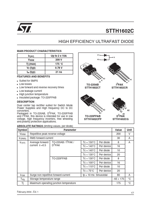
IM
60 50 40
T
80 70
δ=tp/T
tp
60 50
Tj=150°C
P = 15W
30
40
Tj=25°C
30 20 10 0 0.0 0.1 0.2 0.3 0.4
P = 8W P = 3W
20 10
VFM(V)
0.0 0.2 0.4 0.6 0.8 1.0 1.2 1.4 1.6 1.8 2.0 2.2 2.4
IRM(A)
16 14 12 10
IF=8A VR=160V
Fig. 8: Dynamic parameters versus junction temperature.
Qrr;IRM[Tj]/Qrr;IRM[Tj=125°C]
1.4 1.2 1.0 0.8
IRM IF=8A VR=160V
8
Tj=125°C
Pulse test: * tp = 5ms, δ < 2% ** tp = 380µs, δ < 2%
2 2 2 2
Maximum Per diode Per device Per diode Per device 3.0 1.9 5.5 4.5 0.8 3.5
Unit °C/W
°C/W
Min.
Typ.
trr(ns)
80 70 60 50 40 30 20 10
Tj=25°C IF=8A VR=160V
Tj=125°C
dIF/dt(A/µs)
0 10
dIF/dt(A/µs)
100 1000
Fig. 7: Peak reverse recovery current versus dIF/dt (typical values, per diode).
卓一电子 ZYT16微电脑时控开关 说明书
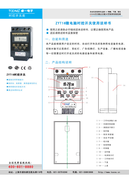
ZYT16时控开关
●超强负荷带载能力
●低价位、高质量,具有超高性价比●具有壁挂式安装方式
●通过CQC和CE认证
ZYT16时控开关
●超强负荷带载能力
●低价位、高质量,具有超高性价比●具有壁挂式安装方式
●通过CQC和CE认证
ZYT16时控开关
●超强负荷带载能力
●低价位、高质量,具有超高性价比●具有壁挂式安装方式
●通过CQC和CE认证
ZYT16时控开关
●超强负荷带载能力
●低价位、高质量,具有超高性价比●具有壁挂式安装方式
●通过CQC和CE认证
ZYT16时控开关
●超强负荷带载能力
●低价位、高质量,具有超高性价比●具有壁挂式安装方式
●通过CQC和CE认证。
ST STP16DPS05 数据手册

January 2010Doc ID 16538 Rev 21/34STP16DPS05Low voltage 16-bit constant currentLED sink driver with outputs error detectionFeatures■Low voltage power supply down to 3 V ■16 constant current output channels ■Adjustable output current through external resistor■Short and open output error detection ■Serial data IN/Parallel data OUT ■ 3.3 V micro driver-able ■Output current: 20-85 mA ■30 MHz clock frequency■Available in high thermal efficiency TSSOP exposed pad■ESD protection 2.0 kV HBM, 200 V MMDescriptionThe STP16DPS05 is a monolithic, low voltage, low current power 16-bit shift register designed for LED panel displays. The device contains a 16-bit serial-in, parallel-out shift register that feeds a 16-bit D-type storage register. In the output stage, sixteen regulated current sources were designed to provide 5-100 mA constant current to drive the LEDs.The STP16DP05 features open and short LED detections on the outputs.The STP16DP05 is backward compatible with STP16C/L596.The detection circuit checks 3 different conditions that can occur on the output line: short to GND, short to V O or open line. The data detection results are loaded in the shift register and shifted out via the serial line output.The detection functionality is implemented without increasing the pin count number, through a secondary function of the LATCH and output enable pin (DM1 and DM2 respectively), a dedicated logic sequence allows the device to enter or leave from detection mode. Through an external resistor, users can adjust theSTP16DPS05 output current, controlling in this way the light intensity of LEDs, in addition, user can adjust LED’s brightness intensity from 0% to 100% via OE/DM2 pin.The STP16DPS05 guarantees a 20 V output driving capability, allowing users to connect more LEDs in series. The high clock frequency,30 MHz, makes the device suitable for high data rate transmission. The 3.3 V voltage supply is well useful for applications that interface any 3.3V micro. Compared with a standard TSSOPpackage, the TSSOP exposed pad increases heat dissipation capability by a 2.5 factor.Table 1.Device summaryOrder codes Package Packaging STP16DPS05MTR SO-24 (tape and reel)1000 parts per reel STP16DPS05TTR TSSOP24 (tape and reel)2500 parts per reel STP16DPS05XTTR TSSOP24 exposed pad(tape and reel)2500 parts per reel STP16DP05PTRQSOP-242500 parts per reelContents STP16DPS05Contents1Summary description . . . . . . . . . . . . . . . . . . . . . . . . . . . . . . . . . . . . . . . . 31.1Pin connection and description . . . . . . . . . . . . . . . . . . . . . . . . . . . . . . . . . 32Electrical ratings . . . . . . . . . . . . . . . . . . . . . . . . . . . . . . . . . . . . . . . . . . . . 42.1Absolute maximum ratings . . . . . . . . . . . . . . . . . . . . . . . . . . . . . . . . . . . . . 42.2Thermal data . . . . . . . . . . . . . . . . . . . . . . . . . . . . . . . . . . . . . . . . . . . . . . . 42.3Recommended operating conditions . . . . . . . . . . . . . . . . . . . . . . . . . . . . . 5 3Electrical characteristics . . . . . . . . . . . . . . . . . . . . . . . . . . . . . . . . . . . . . 6 4Equivalent circuit and outputs . . . . . . . . . . . . . . . . . . . . . . . . . . . . . . . . . 8 5Timing diagrams . . . . . . . . . . . . . . . . . . . . . . . . . . . . . . . . . . . . . . . . . . . 10 6Typical characteristics . . . . . . . . . . . . . . . . . . . . . . . . . . . . . . . . . . . . . . 137Detection mode functionality . . . . . . . . . . . . . . . . . . . . . . . . . . . . . . . . . 167.1Phase one: “entering in detection mode“ . . . . . . . . . . . . . . . . . . . . . . . . . 167.2Phase two: “error detection” . . . . . . . . . . . . . . . . . . . . . . . . . . . . . . . . . . . 177.3Phase three: “resuming to normal mode” . . . . . . . . . . . . . . . . . . . . . . . . . 197.4Error detection conditions . . . . . . . . . . . . . . . . . . . . . . . . . . . . . . . . . . . . . 197.5Auto power-saving . . . . . . . . . . . . . . . . . . . . . . . . . . . . . . . . . . . . . . . . . . 22 8Package mechanical data . . . . . . . . . . . . . . . . . . . . . . . . . . . . . . . . . . . . 25 9Revision history . . . . . . . . . . . . . . . . . . . . . . . . . . . . . . . . . . . . . . . . . . . 332/34 Doc ID 16538 Rev 2STP16DPS05Summary descriptionDoc ID 16538 Rev 23/341 Summary description1.1 Pin connection and descriptionNote:The exposed pad should be electrically connected to a metal land electrically isolated orconnected to ground.Table 2.Typical current accuracyOutput voltageCurrent accuracy Output current V DD TemperatureBetween bitsBetween ICs≥ 1.3 V±1.5%±5%20 to 100 mA3.3 V to 5 V25 °CTable 3.Pin descriptionPin n°Symbol Name and function1GND Ground terminal 2SDI Serial data input terminal 3CLK Clock input terminal4LE/DM1Latch input terminal - detect mode 1 (see operation principle)5-20OUT 0-15Output terminal21OE/DM2Input terminal of output enable (active low) - detect mode 1 (see operation principle)22SDO Serial data out terminal23R-EXT Input terminal of an external resistor for constant current programing 24V DDSupply voltage terminalElectrical ratings STP16DPS054/34 Doc ID 16538 Rev 22 Electrical ratings2.1Absolute maximum ratingsStressing the device above the rating listed in the Table 4 may cause permanent damage tothe device. These are stress ratings only and operation of the device at these or any other conditions above those indicated in the operating sections of this specification is not implied. Exposure to absolute maximum rating conditions for extended periods may affect device reliability.2.2 Thermal dataTable 4.Absolute maximum ratingsSymbol ParameterValue Unit V DD Supply voltage 0 to 7V V O Output voltage -0.5 to 20V I O Output current 100mA V I Input voltage -0.4 to V DDV I GND GND terminal current 1600mA f CLK Clock frequency50MHz T JJunction temperature range (1)1.Such absolute value is achieved according the thermal shutdown-40 to +170°CTable 5.Thermal dataSymbol ParameterValue Unit T OPR Operating temperature range -40 to +125°C T STGStorage temperature range-55 to +150°C R thJAThermal resistance junction-ambient (1)1.According with JEDEC JESD51-7SO-2442.7°C/W TSSOP2455°C/W TSSOP24(2)exposed pad 2.The exposed pad should be soldered directly to the PCB to realize the thermal benefits.37.5°C/W QSOP-2455°C/WSTP16DPS05Electrical ratingsDoc ID 16538 Rev 25/342.3 Recommended operating conditionsTable 6.Recommended operating conditionsSymbol Parameter Test conditionsMin.Typ.Max.Unit V DD Supply voltage 3.0- 5.5V V O Output voltage -20V I O Output current OUTn 5-100mA I OH Output current SERIAL-OUT -+1mA I OL Output current SERIAL-OUT--1mA V IH Input voltage 0.7V DD -V DD +0.3V V IL Input voltage -0.3-0.3 VDDV t wLA T LE/DM1 pulse width V DD = 3.0 V to 5.0 V 6-ns t wCLK CLK pulse width 8-ns t wENOE/DM2 pulse width100-ns t SETUP(D)Setup time for DA T A 10-ns t HOLD(D)Hold time for DA TA 5-ns t SETUP(L)Setup time for LA TCH 10-ns f CLKClock frequencyCascade operation (1)1.If the device is connected in cascade, it may not be possible achieve the maximum data transfer.Please consider the timings carefully.-30MHzElectrical characteristics STP16DPS056/34 Doc ID 16538 Rev 23 Electrical characteristicsV DD = 5 V , T = 25 °C, unless otherwise specifiedTable 7.Electrical characteristicsSymbol ParameterTest conditionsMin.Typ.Max.Unit V IH Input voltage high level 0.7V DD V DD V V IL Input voltage low level GND0.3V DDV I OH Output leakage current V OH = 20 V 1μA V OL Output voltage (Serial-OUT)I OL = 1 mA 0.4V V OH Output voltage (Serial-OUT)I OH = -1 mAV OH -V DD = -0.4 VVI OL1Output currentV O = 0.3 V , R ext = 3.9 k Ω 4.255 5.75mAI OL2V O = 0.3 V , R ext = 970 Ω192021I OL3V O = 1.3 V , R ext = 190 Ω96100104ΔI OL1Output current errorbetween bit (all output ON)V O = 0.3 VR EXT = 3.9 k Ω± 5± 8%ΔI OL2V O = 0.3 VR EXT = 970 Ω± 1.5± 3ΔI OL3V O = 1.3 VR EXT =190 Ω± 1.2± 3R SIN(up)Pull-up resistor 150300600K ΩR SIN(down)Pull-down resistor 100200400K ΩI DD(OFF1)Supply current (OFF)R EXT = 970OUT 0 to 15 = OFF 56mAI DD(OFF2)R EXT = 240OUT 0 to 15 = OFF 1314I DD(ON1)Supply current (ON)R EXT = 970OUT 0 to 15 = ON 67I DD(ON2)R EXT = 240OUT 0 to 15 = ON13.514.5ThermalThermal protection (1)170°C 1.Guaranteed by design (not tested)The thermal protection switches OFF only the outputs currentSTP16DPS05Electrical characteristicsDoc ID 16538 Rev 27/34V DD = 5 V , T = 25 °C, unless otherwise specifiedTable 8.Switching characteristicsSymbol ParameterTest conditionsMin.Typ.Max.Unitt PLH1Propagation delay time, CLK-OUTn, LE/DM1 = H, OE/DM2 = LV IH = V DDV IL = GND C L = 10 pFI O = 20 mA V L = 3.0 V R EXT = 1 K ΩR L = 60 ΩV DD = 3.3 V -40 to 4444ns V DD = 5 V -20 to 4444t PLH2Propagation delay time,LE/DM1 -OUTn,OE/DM2 = LV DD = 3.3 V -5177ns V DD = 5 V -3247t PLH3Propagation delay time,OE/DM2-OUTn,LE/DM1 = HV DD = 3.3 V -49 to 5757 to 77ns V DD = 5 V -27 to 3232 to 41t PLHPropagation delay time, CLK-SDOV DD = 3.3 V -21.5 to 2232nsV DD = 5 V -14.5 to 1521.5t PHL1Propagation delay time, CLK-OUTn, LE/DM1 = H,OE/DM2 = LV DD = 3.3 V -15 to 1825ns V DD = 5 V -11 to 1314.5 to 16t PHL2Propagation delay time,LE/DM1 -OUTn,OE/DM2 = LV DD = 3.3 V -13 to 1818 to 25ns V DD = 5 V -9 to 1212.5 to 15t PHL3Propagation delay time,OE/DM2-OUTn, LE/DM1 = HV DD = 3.3 V -11.5 to 1212 to 18ns V DD = 5 V -8.5 to 109.7 to 12t PHLPropagation delay time, CLK-SDOV DD = 3.3 V -25.538ns V DD = 5 V -17.5 to 20.525t ONOutput rise time 10~90% of voltage waveformV DD = 3.3 V -34 to 2024 to 53.5ns V DD = 5 V -12.5 to 99 to 18.5t OFF Output fall time 90~10% of voltage waveform V DD = 3.3 V - 5.5 to 3.3 3.3 to 8.5ns V DD = 5 V- 4.5 to 2.8 2.8 to 6.5t r CLK rise time (1)-5000ns t fCLK fall time (1)-5000ns1.In order to achieve high cascade data transfer, please consider tr/tf timings carefully.Equivalent circuit and outputs STP16DPS05 4 Equivalent circuit and outputsOE/DM2 terminal8/34 Doc ID 16538 Rev 2STP16DPS05Equivalent circuit and outputsDoc ID 16538 Rev 29/34Timing diagrams STP16DPS0510/34Doc ID 16538 Rev 25 Timing diagramsNote:OUTn = ON when Dn = H OUTn = OFF when Dn = LNote:1Latch and output enable are level sensitive and ARE NOT synchronized with rising-or-fallingedge of CLK signal.2When LE/DM1 terminal is low level, the latch circuits hold previous set of data3When LE/DM1 terminal is high level, the latch circuits refresh new set of data from SDI chain.4When OE/DM2 terminal is at low level, the output terminals - Out0 to Out15 respond to data in the latch circuits, either '1' for ON or '0' for OFF5When OE/DM2 terminal is at high level, all output terminals will be switched OFF .STP16DPS05Timing diagramsDoc ID 16538 Rev 211/34Timing diagrams STP16DPS0512/34 Doc ID 16538 Rev 2STP16DPS05Typical characteristicsDoc ID 16538 Rev 213/346 Typical characteristicsFigure 11.Output current-R EXT resistorTable 10.Output current-R EXT resistorRext (Ω)Output current (mA)9762078025652305603548840433453895035455325603006527870259752418022985Typical characteristics STP16DPS05 Conditions:Temperature = 25 °C, V DD = 3.3 V; 5.0 V, I SET = 3 mA; 5 mA; 10 mA; 20 mA; 50 mA; 80 mA.Table 11.I SET vs drop out voltage (V drop)Iout (mA)****************319.3322.66536.6740.331077.338020158.67157.33504064068069266814/34 Doc ID 16538 Rev 2STP16DPS05Typical characteristicsDoc ID 16538 Rev 215/34Detection mode functionality STP16DPS05 7 Detection mode functionality7.1 Phase one: “entering in detection mode“From the “normal mode” condition the device can switch to the “error mode” by a logicsequence on the OE/DM2 and LE/DM1 pins as showed in the following table and diagram:Table 12.Entering in detection truth tableCLK1°2°3°4°5°OE/DM2H L H H HLE/DM1L L L H LAfter these five CLK cycles the device goes into the “error detection mode” and at the 6thrise front of CLK the SDI data are ready for the sampling.16/34 Doc ID 16538 Rev 2STP16DPS05Detection mode functionality7.2 Phase two: “error detection”The 16 data bits must be set “1” in order to set ON all the outputs during the detection. Thedata are latched by LE/DM1 and after that the outputs are ready for the detection process.When the microcontroller switches the OE/DM2 to LOW, the device drives the LEDs in orderto analyze if an OPEN or SHORT condition has occurred.The LEDs status will be detected at least in 1 microsecond and after this time themicrocontroller sets OE/DM2 in HIGH state and the output data detection result will go tothe microprocessor via SDO.Detection mode and normal mode use both the same format data. As soon as all thedetection data bits are available on the serial line, the device may go back to normal modeof operation. To re-detect the status the device must go back in normal mode and re-entering in error detection mode.Doc ID 16538 Rev 217/34Detection mode functionality STP16DPS0518/34 Doc ID 16538 Rev 2STP16DPS05Detection mode functionalityDoc ID 16538 Rev 219/347.3 Phase three: “resuming to normal mode”The sequence for re-entering in normal mode is showed in the following table and diagram:Note:For proper device operation the “Entering in detection” sequence must be follow by a “resume mode” sequence, it is not possible to insert consecutive equal sequence.7.4 Error detection conditionsV DD = 3.3 to 5 V temperature range -40 to 125 °CNote:Where: I O = the output current programmed by the R EXT , I ODEC = the detected output current in detection modeFigure 17.Resuming to normal mode timing diagramCLK 1°2°3°4°5°OE/DM2H L H H H LE/DM1LLLLLTable 13.Detection conditionsSW-1 or SW-3b Open line or outputshort to GND detected==> I ODEC ≤ 0.5 x I ONo error detected ==> I ODEC ≥ 0.5 x I O SW-2 or SW-3a Short on LED or shortto V-LED detected==> V O ≥ 2.4 VNo error detected==> V O ≤ 2.2 VDetection mode functionalitySTP16DPS0520/34 Doc ID 16538 Rev 2LE/DM1 and OE/DM2 Key Sequence necessary to Enter in EDMThe LE/DM1 pulse latch the data loaded during the previous state After OE/DM2 signal turn High the the device from EDM to Normal ModeSDO pin show the results of Error Detection (Open or Short in this case)The OE/DM2 Pulse putSTP16DPS05Detection mode functionalityDoc ID 16538 Rev 221/34Typical schematic used to perform the error detection:Using the follow formula is possible measure the Iodec I ODEC = (Vled-Vload) / RloadThe tables below shows the I ODEC average value at 3.3 V and 5.0 V of power supply voltage.The I ODEC is the current value recognized by the devices output open error detection Table 14.I ODEC average value at 3.3 VVdd (V)Iset (mA)Rext (Ω)Iout AVG (mA)3.354270 2.097102056 6.7920100610.465038226.928025135.03Table 15.I ODEC average value at 5 VVdd (V)Iset (mA)Rext (Ω)Iout AVG (mA)554270 1.98102056 6.092010069.675038225.548025138.9Detection mode functionality STP16DPS0522/34 Doc ID 16538 Rev 27.5 Auto power-savingThe auto power-saving feature minimizes the quiescent current if no active data is detectedon the latches and auto powers-up the device as the first active data is latched.Figure 21.Auto power-saving featureConditions:Temp. = 25 °C, Vdd = 3.3 V , Vin = Vdd, VLed = 3.0 V, Iset = 20 mACh1 (Y ellow) = IDD, Ch2 (Blue) = SDI, Ch3 (Purple) = LE/DM1, Ch4 (Green) = CLK Idd consumption:Idd (normal operation) = 5.15 mA Idd (shutdown condition) = 163 µASTP16DPS05Detection mode functionalityAfter 16 clock cycles without data change, device will enter in Auto power save mode asexpected. Delay TLE-OUT = 1.053 µsConditions:Temp. = 25 °C, Vdd = 3.3 V, Vin = Vdd, VLed = 3.0 V, Iset = 20 mACh1 (Y ellow) = CLK, Ch2 (Blue) = SDI, Ch3 (Purple) = LE/DM1, Ch4 (Green) = IOUTDoc ID 16538 Rev 223/34Detection mode functionality STP16DPS05Note:When the device goes from auto power-saving to normal operating condition, the first output that switches ON shows the T ON condition as seen in the plot above.Temp. = 25°C, Vdd = 3.3 V, Vin = Vdd, VLed = 3.0 V, Iset = 20 mACh1 (Y ellow) = IDD, Ch2 (Blue) = SDI, Ch3 (Purple) = LE/DM1, Ch4 (Green) = CLK24/34 Doc ID 16538 Rev 2STP16DPS05Package mechanical dataDoc ID 16538 Rev 225/348 Package mechanical dataIn order to meet environmental requirements, ST offers these devices in different grades of ECOPACK ® packages, depending on their level of environmental compliance. ECOPACK ® specifications, grade definitions and product status are available at: . ECOPACK ® is an ST trademark .Table 16.QSOP-24 mechanical dataDim.mm. inchMin.Typ.Max. Min.Typ.Max.A 1.54 1.62 1.730.0610.0640.068A1 0.10.150.250.0040.0060.010A2 1.470.058b 0.310.2 0.0120.008c 0.2540.17 0.0100.007D 8.568.668.760.3370.3410.345E 5.86 6.20.2280.2360.244E1 3.83.914.010.1500.1540.158e 0.6350.025L 0.40.6350.890.0160.0250.035h 0.250.330.410.0100.0130.016< 8° 0°Package mechanical data STP16DPS0526/34 Doc ID 16538 Rev 2STP16DPS05Package mechanical dataTable 17.QSOP-24 tape and reelmm. inch Dim.Min Typ Max Min Typ MaxR112.81313.5 5.039 5.118 5.315R2330129.921R310039.37eint16.4 6.457e1 1.52 2.50.5910.7870.984Doc ID 16538 Rev 227/34Package mechanical dataSTP16DPS0528/34 Doc ID 16538 Rev 2Table 19.TSSOP24 mechanical dataDim.mm. inchMin.Typ.Max.Min.Typ.Max.A 1.1 0.043 A1 0.050.15 0.0020.006A2 0.9 0.035b 0.19 0.30 0.0075 0.0118c 0.09 0.20 0.0035 0.0079 D 7.7 7.9 0.303 0.311 E 4.34.5 0.1690.177e 0.65 BSC 0.0256 BSCH 6.25 6.5 0.246 0.256 K 0° 8° 0° 8° L 0.500.70 0.0200.028Figure 25.TSSOP24 package dimensionsSTP16DPS05Package mechanical dataDoc ID 16538 Rev 229/34Table 20.TSSOP24 tape and reelDim.mm. inchMin.Typ.Max.Min.Typ.Max.A -330 -12.992 C 12.8 -13.2 0.504 -0.519D 20.2 -0.795 -N 60 - 2.362 -T -22.4 -0.882 Ao 6.8 -7 0.268 -0.276 Bo 8.2 -8.4 0.323 -0.331 Ko 1.7 - 1.9 0.067 -0.075 Po 3.9 - 4.1 0.153 -0.161 P 11.9 -12.1 0.468 -0.476Figure 26.Reel dimensionsPackage mechanical dataSTP16DPS0530/34 Doc ID 16538 Rev 2Table 21.SO-24 mechanical dataDim.mm. inchMin.Typ.Max.Min.Typ.Max.A 2.65 0.104 a1 0.10.2 0.0040.008a2 2.45 0.096 b 0.35 0.49 0.014 0.019 b1 0.230.32 0.0090.012C 0.5 0.020c1 45°(typ.) D 15.20 15.60 0.598 0.614 E 10.0010.65 0.3930.419e 1.27 0.050 e3 13.97 0.550F 7.40 7.60 0.291 0.300 L 0.501.27 0.0200.050S °(max.) 8Figure 27.SO-24 package dimensionsSTP16DPS05Package mechanical dataDoc ID 16538 Rev 231/34Table 22.SO-24 tape and reelDim.mm. inchMin.Typ.Max.Min.Typ.Max.A -330 -12.992 C 12.8 -13.2 0.504 -0.519D 20.2 -0.795 -N 60 - 2.362 -T -30.4 - 1.197 Ao 10.8 -11.0 0.425 -0.433 Bo 15.7 -15.9 0.618 -0.626 Ko 2.9 - 3.1 0.114 -0.122 Po 3.9 - 4.1 0.153 -0.161 P 11.9 -12.1 0.468 -0.476Figure 28.Reel dimensionsPackage mechanical dataSTP16DPS0532/34 Doc ID 16538 Rev 2Table 23.TSSOP24 exposed padDim.mm inchMin.Typ.Max.Min.Typ.Max.A 1.2 0.047A1 0.15 0.004 0.006A2 0.8 1 1.05 0.031 0.039 0.041 b 0.19 0.30 0.007 0.012 c 0.090.20 0.0040.0089D 7.7 7.8 7.9 0.303 0.307 0.311 D1 4.75.05.30.1850.1970.209E 6.2 6.4 6.6 0.244 0.252 0.260 E1 4.3 4.4 4.5 0.169 0.173 0.177 E2 2.93.23.50.1140.1260.138e 0.65 0.0256K 0°8° 0°8°L 0.45 0.60 0.75 0.018 0.024 0.030Figure 29.TSSOP24 dimensionsSTP16DPS05Revision historyDoc ID 16538 Rev 233/349 Revision historyTable 24.Document revision historyDate RevisionChanges23-Oct-20091First release22-Jan-20102Updated T able 5 on page 4STP16DPS05Please Read Carefully:Information in this document is provided solely in connection with ST products. STMicroelectronics NV and its subsidiaries (“ST”) reserve the right to make changes, corrections, modifications or improvements, to this document, and the products and services described herein at any time, without notice.All ST products are sold pursuant to ST’s terms and conditions of sale.Purchasers are solely responsible for the choice, selection and use of the ST products and services described herein, and ST assumes no liability whatsoever relating to the choice, selection or use of the ST products and services described herein.No license, express or implied, by estoppel or otherwise, to any intellectual property rights is granted under this document. If any part of this document refers to any third party products or services it shall not be deemed a license grant by ST for the use of such third party products or services, or any intellectual property contained therein or considered as a warranty covering the use in any manner whatsoever of such third party products or services or any intellectual property contained therein.UNLESS OTHERWISE SET FORTH IN ST’S TERMS AND CONDITIONS OF SALE ST DISCLAIMS ANY EXPRESS OR IMPLIED WARRANTY WITH RESPECT TO THE USE AND/OR SALE OF ST PRODUCTS INCLUDING WITHOUT LIMITATION IMPLIED WARRANTIES OF MERCHANTABILITY, FITNESS FOR A PARTICULAR PURPOSE (AND THEIR EQUIVALENTS UNDER THE LAWS OF ANY JURISDICTION), OR INFRINGEMENT OF ANY PATENT, COPYRIGHT OR OTHER INTELLECTUAL PROPERTY RIGHT. UNLESS EXPRESSLY APPROVED IN WRITING BY AN AUTHORIZED ST REPRESENTATIVE, ST PRODUCTS ARE NOT RECOMMENDED, AUTHORIZED OR WARRANTED FOR USE IN MILITARY, AIR CRAFT, SPACE, LIFE SAVING, OR LIFE SUSTAINING APPLICATIONS, NOR IN PRODUCTS OR SYSTEMS WHERE FAILURE OR MALFUNCTION MAY RESULT IN PERSONAL INJURY, DEATH, OR SEVERE PROPERTY OR ENVIRONMENTAL DAMAGE. ST PRODUCTS WHICH ARE NOT SPECIFIED AS "AUTOMOTIVE GRADE" MAY ONLY BE USED IN AUTOMOTIVE APPLICATIONS AT USER’S OWN RISK.Resale of ST products with provisions different from the statements and/or technical features set forth in this document shall immediately void any warranty granted by ST for the ST product or service described herein and shall not create or extend in any manner whatsoever, any liability of ST.ST and the ST logo are trademarks or registered trademarks of ST in various countries.Information in this document supersedes and replaces all information previously supplied.The ST logo is a registered trademark of STMicroelectronics. All other names are the property of their respective owners.© 2010 STMicroelectronics - All rights reservedSTMicroelectronics group of companiesAustralia - Belgium - Brazil - Canada - China - Czech Republic - Finland - France - Germany - Hong Kong - India - Israel - Italy - Japan - Malaysia - Malta - Morocco - Philippines - Singapore - Spain - Sweden - Switzerland - United Kingdom - United States of America34/34 Doc ID 16538 Rev 2。
OW16 系列数字万用表 用户手册说明书

OW16系列数字万用表用户手册⏹OW16A⏹OW16B官方微信,一扫即得2018.12版本V1.0.2©福建利利普光电科技有限公司版权所有,保留所有权利。
产品受专利权的保护,包括已取得的和正在申请的专利。
本文中的信息将取代所有以前出版资料中的信息。
本手册信息在印刷时是正确的。
然而,福建利利普光电科技有限公司将继续改进产品并且保留在任何时候不经通知的情况下变动规格的权利。
是福建利利普光电科技有限公司的注册商标。
福建利利普光电科技有限公司福建漳州市蓝田工业开发区鹤鸣路(原横三路)19号利利普光电科技楼Tel: 4006-909-365 Fax:************Web: E-mail:*************.cn保修概要OWON 保证,本产品从OWON 公司最初购买之日起一年期间,不会出现材料和工艺缺陷。
本有限保修仅适于原购买者且不得转让第三方。
如果产品在保修期内确有缺陷,则OWON 将按照完整的保修声明所述,提供维修或更换服务。
但此保修不包括保险丝、一次性电池或者由于意外事故、疏忽、滥用、改造、污染及操作环境的反常而造成的损害。
如果在适用的保修期内证明产品有缺陷,OWON 可自行决定是修复有缺陷的产品且不收部件和人工费用,还是用同等产品(由OWON 决定)更换有缺陷的产品。
OWON 作保修用途的部件、模块和更换产品可能是全新的,或者经维修具有相当于新产品的性能。
所有更换的部件、模块和产品将成为OWON 的财产。
为获得本保证承诺的服务,客户必须在适用的保修期内向OWON 通报缺陷,并为服务的履行做适当安排。
客户应负责将有缺陷的产品装箱并运送到OWON 指定的维修中心,同时提供原购买者的购买证明副本。
本保证不适用于由于意外、机器部件的正常磨损、在产品规定的范围之外使用、使用不当或者维护保养不当或不足而造成的任何缺陷、故障或损坏。
OWON 根据本保证的规定无义务提供以下服务:a) 维修由非OWON 服务代表人员对产品进行安装、维修或维护所导致的损坏;b) 维修由于使用不当或与不兼容的设备连接造成的损坏;c) 维修由于使用非OWON 提供的电源而造成的任何损坏或故障;d) 维修已改动或者与其他产品集成的产品(如果这种改动或集成会增加产品维修的时间或难度)。
新普特 i16 温度传感器控制器说明书
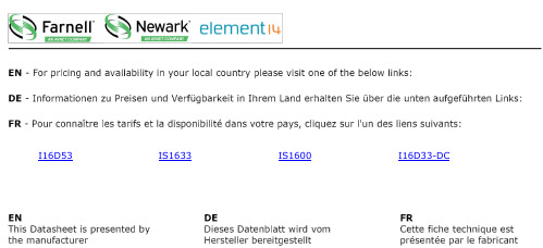
I16D53IS1633IS1600I16D33-DCU Universal Inputs U H igh Accuracy: 0.5°C (±0.9°F), 0.03% Reading U Totally Programmable Color Displays (Visual Alarms)U User-Friendly,Simple to Configure U Free SoftwareU Full Autotune PID Control U Embedded Ethernet Connectivity Optional U RS232 and RS485 Serial Communications Optional U Built-In Excitation U 2 Control or Alarm Outputs Optional: DC Pulse, Solid State Relays, Mechanical Relays, Analog Voltage and CurrentU Output 3: Isolated Analog Voltage and Current OptionalU NEMA 4 (IP65) Front Bezel U Temperature Stability ±0.04°C/°C RTD and±0.05°C/°C Thermocouple @ 25°C (77°F)U Front Removable and Plug ConnectorsU AC or DC Powered Units U Ratiometric Mode for Strain Gages U Programmable Digital FilterThe NEWPORT ® i16 is the popular 1⁄16 DIN size (48 mm 2) controller. It is available with a single (model i16) or dual display (model i16D) that displays a setpoint along with the process value. The i16 display can be programmed to change color between GREEN, AMBER , and RED at any setpoint or alarm point. The i16 is the first 1⁄16 DIN controller with the option of both RS232 and RS485 in 1 instrument with both MODBUS ® serial protocoland the straightforward Newport ® ASCII protocol. And of course the i16 is the first 1⁄16 DIN controller that can connect directly to an Ethernet network and features an embedded Web server. Newport ® provides free configuration and data acquisition software downloaded off of the Web.The i16 enclosure has aNEMA 4 (IP65) rated front bezel. The electronics are removable from the front panel.i16D33 shown largerthan actual size.i1633 shown larger than actual size.1⁄16 DIN Temperature, Process andStrain PID Controllersi16 SeriesAccess Vital information Anytime,Anywhere, on the Internet!1⁄16 DIN controller withembedded Web server, dual control outputs, dual display.Ordering Examples: i1633, temperature/process controller,output 1 relay, output 2 relay single display, 90 to 240 Vac power.iS1643, strain/process controller, output 1 DC pulse, output 2relay, single display, 90 to 240 Vac power.*1 Ethernet options are available for the i16D and iS16D controllers only.*2 “-DC”, “-C24”, and “-C4EIT ” not available with excitation.*3 Analog output (option 5) is not available with “-AL ” units or i16A models.*4 20 to 36 Vdc for i16D , i16D-C4EIT , i16D-EIT and i16A *5 “-SM ” option not available on iS16 or i16A models.*6 Ethernet options are not available for i16A models.*7 For i16Axx-AL: One alarm and one analog retransmission.Universal Temperature and Process Input ("i" Models)Accuracy: ±0.5°C temp; 0.03% rdg Resolution: 1°/0.1°; 10 μV process Temperature Stability: RTD: 0.04°C/°CTC @ 25°C (77°F): 0.05°C/°C Cold Junction Compensation Process: 50 ppm/°C NMRR: 60 dB CMRR: 120 dBA/D Conversion: Dual slope Reading Rate: 3 samples/s Digital Filter: Programmable Display: 4-digit 9-segment LED 10.2 mm (0.40"); i32, i16, i16D, i8DV 21 mm (0.83"); i8 10.2 mm (0.40") and 21 mm (0.83"); i8DH RED , GREEN , and AMBER programmable colors for process variable, setpoint and temperature unitsInput Types: Thermocouple, RTD, analog voltage, analog currentThermocouple Lead Resistance: 100 Ω maxThermocouple Types (ITS 90): J, K, T, E, R, S, B, C, N, L (J DIN)RTD Input (ITS 68): 100/500/1000 Ω Pt sensor, 2-, 3- or 4-wire; 0.00385 or 0.00392 curveVoltage Input: 0 to 100 mV, 0 to 1V, 0 to 10 VdcInput Impedance: 10 M Ω for 100 mV 1 M Ω for 1 or 10 VdcCurrent Input: 0 to 20 mA (5 Ω load)Configuration: Single-ended Polarity: UnipolarStep Response: 0.7 sec for 99.9%Decimal Selection: Temperature: None, 0.1 Process: None, 0.1, 0.01 or 0.001Setpoint Adjustment: -1999 to 9999 counts Span Adjustment: 0.001 to 9999 countsOffset Adjustment: -1999 to 9999Excitation (Not Included withCommunication): 24 Vdc @ 25 mA (not available for low-power option)Universal Strain and Process Input ("iS" Models)Accuracy: 0.03% reading Resolution: 10/1μVTemperature Stability: 50 ppm/°C NMRR: 60 dB CMRR: 120 dBA/D Conversion: Dual slope Reading Rate: 3 samples/s Digital Filter: ProgrammableInput Types: Analog voltage and current Voltage Input: 0 to 100 mVdc, -100 mVdc to 1 Vdc, 0 to 10 VdcInput Impedance: 10 M Ω for 100 mV; 1 M Ω for 1V or 10 VdcCurrent Input: 0 to 20 mA (5 Ω load)Linearization Points: Up to 10Configuration: Single-ended Polarity: UnipolarStep Response: 0.7 sec for 99.9%Decimal Selection: None, 0.1, 0.01 or 0.001Setpoint Adjustment: -1999 to 9999 countsSpan Adjustment: 0.001 to 9999 counts Offset Adjustment: -1999 to 9999Excitation (Optional In Place Of Communication): 5 Vdc @ 40 mA; 10 Vdc @ 60 mAControlAction: Reverse (heat) or direct (cool)Modes: Time and amplitude proportional control; selectable manual or auto PID, proportional, proportional with integral, proportional with derivative and anti-reset Windup, and on/off Rate: 0 to 399.9 s Reset: 0 to 3999 sCycle Time: 1 to 199 s; set to 0 for on/off Gain: 0.5 to 100% of span; setpoints 1 or 2Damping: 0000 to 0008Soak: 00.00 to 99.59 (HH:MM), or OFF Ramp to Setpoint:00.00 to 99.59 (HH:MM), or OFF Auto Tune: Operator initiated from front panelControl Output 1 and 2Relay: 250 Vac or 30 Vdc @ 3 A (resistive load); configurable for on/off, PID and ramp and soakOutput 1: SPDT, can be configured as alarm 1 outputOutput 2: SPDT, can be configured as alarm 2 outputSSR: ******************.5A (resistive load); continuousDC Pulse: Non-isolated; 10 Vdc @ 20 mA Analog Output (Output 1 Only):Non-isolated, proportional 0 to 10 Vdc or 0 to 20 mA; 500 Ω maxOutput 3 Retransmission:Isolated Analog Voltage and Current Current: 10 V max @ 20 mA output Voltage: 20 mA max for 0 to 10 V output Network and CommunicationsEthernet: Standards compliance IEEE 802.3 10 Base-T Supported Protocols: TCP/IP, ARP, HTTPGETRS232/RS422/RS485: Selectable from menu; both ASCII and Modbus protocol selectable from menu; programmable 300 to 19.2 Kb; complete programmable setup capability; program to transmit current display, alarm status, min/max, actual measured input value and statusCommon Specifications(All i/8, i/16, i/32 DIN)RS485: Addressable from 0 to 199 Connection: Screw terminalsAlarm 1 and 2 (Programmable)Type: Same as output 1 and 2Operation: High/low, above/below, band, latch/unlatch, normally open/ normally closed and process/deviation; front panel configurationsAnalog Output (Programmable):Non-isolated, retransmission 0 to 10 Vdc or 0 to 20 mA, 500 Ω max (output 1 only); accuracy is ±1% of FS when following conditions are satisfied: input is not scaled below 1% of input FS, analog output is not scaled below 3% of output FSGeneralPower: 90 to 240 Vac ±10%, 50 to 400Hz*, 110 to 375 Vdc, equivalent voltageLow Voltage Power Option: 24 Vac**, 12 to 36 Vdc for i/iS; 20 to 36 Vdc for dual display, ethernet, and isolated analog output from qualified safety approved source IsolationPower to Input/Output: 2300 Vac per 1 minute testFor Low Voltage Power Option: 1500 Vac per 1 minute test Power to Relay/SSR Output: 2300 Vac per 1 minute testRelay/SSR to Relay/SSR Output: 2300 Vac per 1 minute test RS232/485 to Input/Output: 500 Vac per 1 minute test Environmental Conditions:All Models: 0 to 55°C (32 to 131°F) 90% RH non-condensing Dual Display Models:0 to 50°C (32 to 122°F), 90% RH non-condensing (for UL only)Protection:i/iS32, 16, 16D, 8C:NEMA 4X/Type 4 (IP65) front bezel i/iS8, 8DH, 8DV:NEMA 1/Type 1 front bezel Approvals: UL, C-UL, CE perEN61010- 1:2001, FM (temperature units only)Dimensionsi/8 Series: 48 H x 96 W x 127 mm D (1.89 x 3.78 x 5")i/16 Series: 48 H x 48 W x 127 mm D (1.89 x 1.89 x 5")i/32 Series: 25.4 H x 48 W x 127 mm D (1.0 x 1.89 x 5")Panel Cutouti/8 Series: 45 H x 92 mm W (1.772 x 3.622"), 1⁄8 DINi/16 Series: 45 mm (1.772") square, 1⁄16 DINi/32 Series: 22.5 H x 45 mm W (0.886 x 1.772"), 1⁄32 DIN Weighti/8 Series: 295 g (0.65 lb) i/16 Series: 159 g (0.35 lb) i/32 Series: 127 g (0.28 lb)* No CE compliance above 60 Hz.** Units can be powered safely with 24 Vacpower, but no certification for CE/UL are claimed.I16D53IS1633IS1600I16D33-DC。
Perkadox 16产品数据表说明书

Product Data SheetPerkadox 16Di(4-tert-butylcyclohexyl) peroxydicarbonatePerkadox® 16 is applied as an initiator for the suspension and mass polymerization of vinyl chloride in the temperature range between 40°C and 65°C. Perkadox® 16 can be used alone or in combination with other peroxides, such as 1,1,3,3-Tetramethylbutyl peroxyneodecanoate (Trigonox 423), Cumyl peroxyneodecanoate (Trigonox 99) or Dilauroyl peroxide (Laurox), to increase reactor efficiency.CAS number15520-11-3EINECS/ELINCS No.239-557-1TSCA statuslisted on inventoryMolecular weight398.5SpecificationsAppearance White powderAssay94.0-97.0 %Inorganic + organic hydrolysable chloride≤ 4000 mg/kgCharacteristicsBulk density, 20 °C450-480 kg/m³Density, 20 °C 1.13 g/cm³ApplicationsPerkadox® 16 can be used for the market segments: polymer production, thermoset composites and acrylics with their different applications/functions. For more information please check our website and/or contact us.Half-life dataThe reactivity of an organic peroxide is usually given by its half-life (t½) at various temperatures. For Perkadox® 16 in chlorobenzene:0.1 hr82°C (180°F)1 hr64°C (147°F)10 hr48°C (118°F)Formula 1kd = A·e-Ea/RTFormula 2t½ = (ln2)/kdEa126.39 kJ/moleA7.44E+15 s-1R8.3142 J/mole·KT(273.15+°C) KThermal stabilityOrganic peroxides are thermally unstable substances, which may undergo self-accelerating decomposition. The lowest temperature at which self-accelerating decomposition of a substance in the original packaging may occur is the Self-Accelerating Decomposition Temperature (SADT). The SADT is determined on the basis of the Heat Accumulation Storage Test.SADT40°CEmergency temperature (Tₑ)35°CControl temperature (Tc)30°CMethod The Heat Accumulation Storage Test is a recognized test method for thedetermination of the SADT of organic peroxides (see Recommendations on theTransport of Dangerous Goods, Manual of Tests and Criteria – United Nations,New York and Geneva).StorageDue to the relatively unstable nature of organic peroxides a loss of quality can be detected over a period of time. To minimize the loss of quality, Nouryon recommends a maximum storage temperature (Ts max. ) for each organic peroxide product.Ts max.20°C (please see note below)Note When stored under the recommended storage conditions, Perkadox® 16 willremain within the Nouryon specifications for a period of at least 3 months afterdelivery. The Ts max of 20°C is not to be interpretated as ambient or roomtemperature as this differs per region and season. Perkadox® 16 has a high qualitycomposition and to hold that it should be stored at below 20°C. At temperaturesabove 20°C the decomposition of Perkadox® 16 progresses fast which leads tosignificant loss of quality. If you have questions about this, please contact yourlocal Nouryon account manager for advice.Packaging and transportIn North America Perkadox® 16 is packed in non-returnable cartons containing 25 polyethylene bags of 1 lb net weightor 5 polyethylene bags of 5 lb net weight. In other regions the standard packaging is a cardboard box for 20 kg peroxide. Both packaging and transport meet the international regulations. For the availability of other packed quantities contact your Nouryon representative. Perkadox® 16 is classified as Organic peroxide type C; solid, temperature controlled; Division 5. 2; UN 3114.Safety and handlingKeep containers tightly closed. Store and handle Perkadox® 16 in a dry well-ventilated place away from sources of heat or ignition and direct sunlight. Never weigh out in the storage room. Avoid contact with reducing agents (e. g. amines), acids, alkalis and heavy metal compounds (e. g. accelerators, driers and metal soaps). Please refer to the Safety Data Sheet (SDS) for further information on the safe storage, use and handling of Perkadox® 16. This information should be thoroughly reviewed prior to acceptance of this product. The SDS is available at /sds-search.Major decomposition products Carbon dioxide, 4-tert-Butyl-cyclohexanolAll information concerning this product and/or suggestions for handling and use contained herein are offered in good faith and are believed to be reliable.Nouryon, however, makes no warranty as to accuracy and/or sufficiency of such information and/or suggestions, as to the product's merchantability or fitness for any particular purpose, or that any suggested use will not infringe any patent. Nouryon does not accept any liability whatsoever arising out of the use of or reliance on this information, or out of the use or the performance of the product. Nothing contained herein shall be construed as granting or extending any license under any patent. Customer must determine for himself, by preliminary tests or otherwise, the suitability of this product for his purposes.The information contained herein supersedes all previously issued information on the subject matter covered. The customer may forward, distribute, and/or photocopy this document only if unaltered and complete, including all of its headers and footers, and should refrain from any unauthorized use. Don’t copythis document to a website.Perkadox® and Trigonox are registered trademarks of Nouryon Functional Chemicals B.V. or affiliates in one or more territories.Contact UsPolymer Specialties Americas************************Polymer Specialties Europe, Middle East, India and Africa*************************Polymer Specialties Asia Pacific************************2023-1-10© 2023Polymer production Perkadox 16。
SAN-16中文资料

GAMEWELL-FCI12 Clintonville Road, Northford, CT 06472-1610 USA • Tel: (203) 484-7161 • Fax: (203) 484-7118Specifications are for information only, are not intended for installation purposes, and are subject to change without notice. No responsibility is assumed by Gamewell-FCI for their use.©2007 Honeywell International Inc. All rights CS-2027 Rev. A page 1 of 2600 Series SAN, SAN-RCSerial Annunciator DriverDescriptionThe 600 Series serial annunciator driver (SAN) is used to light a lamp or LED in an annunciator. It also provides a switched positive output per point for interface with building automation systems or driving relays. Each device is capa-ble of interpreting the instructions from the main CPU, initi-ating its own programmed response, and retransmitting the instructions to the next device.The Gamewell-FCI 600 systems can accommodate up to 64 devices connected to the serial communications port. In addition to the serial annunciator drives (SAN), these devices include remote annunciator (R AN) and remote printer interface (R PI). This combination of devices com-prise the Gamewell-FCI status control network. Since each device contains its own microprocessor, each can be pro-grammed independently. A series of devices can be pro-grammed directly over the network from a single device,saving valuable installation time. Programming is accom-plished via Windows ®-based configuration software.Each SAN input point can activate up to five output points for matrix annunciation. There are two basic models avail-able, the SAN and the SAN-RC. The SAN-16 is equipped with 16 freely programmable outputs which can be used for remote control or monitoring, expandable to 128 points using PDM modules.The SAN-16-RC has all of the features of the SAN-16, plus the ability to read inputs into the system. The SAN-16-RC has provisions for four inputs for: remote acknowledge,reset, signal silence, and lamp test. In addition to the basic 16 outputs, there are eight (8) common outputs for: com-mon system alarm, common system trouble, AC power,communications, action required LED prompts for system acknowledge, reset and signal silence, and a driver for a local audible.The status control network, including SAN units, is con-nected to the main 600 Series control panel via an RS-232data communication line. The SIM-232 module is used toFeatures•Up to 64 devices supported on a single 600 Series control panel.•Windows ®-based field programming.•Dual optically isolated serial ports.•Can interface with building automation systems via standard ASCII communication.•Microprocessor based.•Expandable in 16 point increments to 128 points.Supervised.•Allows remote system control.•Mounting track included.An ISO 9000-2000 Company7120-1288:149SIGNALINGS521SAN, SAN-RCMicrosoft ® Windows ® is a registered trademark of Microsoft ® Corporation.g w f 2027p h 1.w m fGAMEWELL-FCI12 Clintonville Road, Northford, CT 06472-1610 USA • Tel: (203) 484-7161 • Fax: (203) 484-7118CS-2027 Rev. A page 2 of 2 provide an isolated RS-232 output from the main CPU of the 600 Series system panels. The IF602 and IF610 panels have built-in RS-232 ports.ApplicationsThe SAN units provide a means for remote annunciation and control of the system via a simple RS-232 connection.These driver units fit neatly into an annunciator unit and can be used to drive the LED or incandescent lights of a standard or graphic-type annunciator. When it is necessary for remote system control, the SAN-16-RC provides for up to eight inputs for system control. Any or all inputs may be used to customize any given command station’s capabili-ties.The SAN units can also be used to interface with other building systems via ASCII or where dry contacts or a switched output is required. The SAN’s outputs can be used to drive a relay to interface or control virtually any remote point or group of points.Engineer’s SpecificationsRemote annunciation and control for the main control panel shall be supplied where indicated. R emote annunciation and control shall be accomplished via the R S-232 data communications line. It shall be possible to add up to 64devices to the communication line. Each device shall be capable of driving up to 128 points. It shall be possible to mix annunciators, printers and LCD alphanumeric displays on a single line without the need for special software.Devices shall not be placement sensitive. All devices shall be individually field programmable and independent from each other. The device shall be Gamewell-FCI part numbers..SpecificationsSerial AnnunciatorDriver: Basic SAN and SAN-RC provide 16-point drives.SANInput Power:24 VAC/VDC Standby Current:0.04 A max.Alarm Current: 2.0 A max.Output Power:0.040 A max. per output.Dimensions:12” W x 4” H x 2” D(30.5 W x 10.2 H x 5.1 D cm)PDM-16 Point Drive ModuleInput Power:From SAN Module Standby Current:0.002 A Alarm Current:0.002 AOrdering InformationModelDescriptionSAN-16Serial annunciator driver module, main driver with 16-outputs.SAN-#Serial annunciator driver module, specifynumber of outputs in 16-point increments (i.e., SAN-32, SAN-48, SAN-128). Includes mounting track and interconnect cables.Contact the Gamewell-FCI Technical Support for details.SAN-16-RC Serial annunciator driver with four-remotecontrol inputs, eight (8) common outputs and 16-outputs.SAN-#-RC Serial annunciator driver with four- remotecontrol inputs, eight (8) common outputs and a specifiable number of outputs in 16-point increments (i.e., SAN-32-RC, SAN-48-RC, SAN-128-RC). Includes mounting track and interconnect cables.Contact Gamewell-FCI Technical Support for details.PDM-16Point driver module for field-expandingserial annunciator drivers, 16 outputs.SIM-232Required serial interface module, mounts in600 Series control 632, 654, and 658 to sup-ply RS-232 ouputs.Note: This model is not required for use with the IF602 and IF610 Systems.GW70703Programming cable (Programmed via aWindows ®-based SAN program). Found on the Gamewell-FCI website.Note: This program is only available to Gamewell-FCI authorized distributors.。
SinOne SCT80S16B 10V CS 8 通道触控按键专用 IC 说明书

SCT80S16B SinOne10V CS 8通道触控按键专用IC 目录目录 (1)1 总体描述 (3)2 主要功能和优势 (3)2.1 功能 (3)2.2 优势 (3)3 管脚定义 (3)3.1 管脚配置 (3)3.2 管脚定义 (4)4 电气性能 (4)4.1 推荐工作条件 (4)4.2 直流电气特性 (4)5 封装信息 (5)6 应用设计指南 (6)6.1 未使用通道处理 (6)6.2 邻键距离 (6)6.3 通讯输出选择 (6)6.3.1 通讯输出选择OUTS (6)6.3.2 灵敏度设置和键值读取格式 (6)7 注意事项 (9)7.1 典型应用电路 (9)7.2 电路Check List (9)7.3 电源要求 (9)7.4 PCB布局 (9)7.5 PCB布线 (10)7.6 PCB参考图 (10)Page 1 of 11 V 1.17.7 触控面板材料选择 (10)8 规格更改记录 (11)1 总体描述SCT80S16B 是一颗有8个触控通道,带UART/IIC 通讯接口的触控专用IC ,用户可通过UART/IIC 通讯来设置灵敏度。
此IC 具有工业级规格,拥有4KV EFT 和6KV 接触ESD 能力,可顺利通过3V 动态和10V 静态CS 测试,是用户高性能触控按键方案的首选。
非常适合应用于大小家电、安防、工控等应用场合。
2 主要功能和优势2.1 功能● 工作电压:3.3V ~ 5.5V ● 工作温度:-40 ~ 85℃● 触控按键通道:8通道,最多支持两个按键同时被按下 ● 触控按键输出通讯协议:UART/IIC 输出 ● 灵敏度调节:UART/IIC 通讯调节● 上电2s 内可通过UART/IIC 通讯来设置触控通道灵敏度等级 ● 覆盖物厚度:0 ~ 10mm● 有效触摸反应时间:小于100ms ● 允许按键长按时间为10S ●封装:SOP162.2 优势● 发明专利,业界独创; ● 完美触控按键操作体验; ● 用户根据需要设置灵敏度;●超强抗干扰能力,4KV EFT 、6KV ESD 、10V CS 。
PB1602SOP16V1.2

5.5
V
3.2
4.5
V
--
21
35
uA
VBAT=4.2V&VF=2.7~3.4V(IF=30mA)
30
照明LED灯电流IWLED
--
VBAT=4.2V&VF=2.7~3.4V(IF=20mA)
20
--
mA
电量指示LED灯电流ILED1~4 电量指示LED灯闪烁最小脉
冲宽度tSHINE
输出无负载判断阈值IOUT_NO
3、 PB1602内置适配器插入检测开机功能,在待机状态下,如果接上适配器,且适配器输入电压在3.0V
以上时,系统自动开机。如果适配器输入电压高于电池电压,则同时启动充电功能,LED指示转为充
电状态指示。
具体开机情况如下:
(1) VBAT>VDCIN>3.0V: LED显示,不充电,BOOST控制器不启动; (2) VDCIN>VBAT>3.0V:LED显示,开始充电, BOOST控制器不启动;
--
±1
uA
±1
uA
涓流充电阈值电压VTRC
涓流充电电流ITRC 饱和判断电流阈值ITERM 热限制起始温度TempLIM
软启动时间tSS 回充判断时间tRECH 饱和判断时间tTERM
VBAT Low to High VBAT High to Low VBAT <VTRC,RISET=1k
3.0
V
--
--
2.9
V
--
100
--
mA
RISET=1k
--
100
--
mA
--
110
--
℃
MST-6M16规格书

T6612.1/2 规格书
(LCD TV 泛亚太 机芯板)
文件编号:VS_09111001
编制: Fancy 审核: Michael 批准: Allan 版本: V1.3 日期: 2009.11.10
深圳视景电子有限公司
地址: 深圳市福田区福民路知本大厦 9E TEL: +86-755-83042782 83042783 FAX: +86-755-83042786
脚位号
名称
说明
1
5V
5V电源
2
光敏控制信号
光敏控制信号输入
J15 (5PIN-2.0):AV3图像和声音输入
脚位号
名称
说明
1
V
CVBS 图像信号输入
2
GND
地
3
L
左声道信号输入
4
GND
地
5
R
右声道信号输入
J4(6PIN-2.0): DVD控制接口
脚位号
名称
说明
1
DVD12V
DVD/或其它外置设备12V供电输入电源
名称 VCC VCC VCC GND GND GND LVA0LVA0+ LVA1LVA1+ LVA2LVA2+ GND GND LVACKLVACK+ LVA3LVA3+ LVB0LVB0+ LVB1LVB1+ LVB2LVB2+ GND GND LVBCKLVBCK+ LVB3LVB3+ 3V3 GND 3V3 DISPALY SC/V SD/V LVA4LVA4+ LVB4LVB4+
规格参数
视频输入
ST16示波器的使用说明
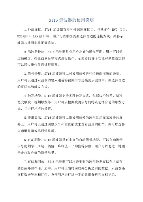
ST16示波器的使用说明1.外部连接:ST16示波器有多种外部连接接口,包括多个BNC接口、USB接口、LAN接口等。
用户可以根据需要选择合适的连接方式,并将示波器与被测电路正确连接。
2.示波器控制:ST16示波器具有用户友好的操作界面,用户可以通过触摸屏、按钮或鼠标等方式进行操作。
示波器的各个功能和参数设定都可以通过操作界面进行调整。
3.信号采集:ST16示波器可以对被测信号进行快速而准确的采集。
用户可以通过示波器的输入通道将被测信号连接到示波器中,并选择合适的采样率和触发方式。
4.触发功能:ST16示波器支持多种触发方式,包括边沿触发、脉冲宽度触发、视频触发等。
用户可以根据被测信号的特点选择合适的触发方式,并进行相应的设置。
5.波形显示:ST16示波器可以将被测信号的波形显示在示波器的屏幕上。
用户可以通过调整水平和垂直缩放来查看波形的细节,并可以选择多通道显示或单通道显示。
6.自动测量:ST16示波器具有丰富的自动测量功能,可以自动测量信号的频率、周期、幅值、峰峰值、平均值等参数。
用户可以通过一键测量来获取准确的测量结果。
7.存储和回放:ST16示波器可以将采集到的波形数据存储在内部存储器或外部存储介质中,用户可以随时回放并分析之前的数据。
示波器还支持数据导出和打印,方便用户进行进一步的数据分析和文档记录。
8.高级功能:ST16示波器还具有一些高级功能,如逻辑分析、频谱分析、串行总线分析等。
用户可以根据需要进行相应的设置和使用,提升工作效率和分析能力。
9.软件支持:ST16示波器配备了专业的软件支持,用户可以通过连接示波器和电脑来进行数据传输和分析。
软件支持数据图表显示、数据处理、自动报告生成等功能,方便用户进行更深入的数据分析和处理。
总结:ST16示波器是一种高性能、多功能的示波器,具有丰富的功能和便捷的操作方式。
用户可以根据需要选择合适的连接方式,并通过触摸屏、按钮或鼠标等方式进行操作。
ST16示波器的使用说明

ST16示波器的使用说明ST-16示波器的使用说明示波器是有着极其广泛用途的测量仪器之一.借助示波器能形象地观察波形的瞬变过程,还可以测量电压。
电流、周期和相位,检查放大器的失真情况等.示波器的型号很多,它的基本使用方法是差不多的.下面以通用ST一16型示波器为例,介绍示波器的使用方法。
面板上旋钮或开关的功能图1是ST一16型示波器的面板图示波器是以数字座标为基础来显示波形的.通常以X轴表示时间,Y轴表示幅度.因而在图1中,面板下半部以中线为界,左面的旋钮全用于Y轴,右面的旋钮全用于X轴。
面板上半部分为显示屏。
显示屏的右边有三个旋钮是调屏幕用的.所有的旋钮,开关功能见表1。
其中8、10,14,16号旋钮不需经常调,做成内藏式。
显示屏读数方法在显示屏上,水平方向X轴有10格刻度,垂直方向Y轴有8格刻度.这里的一格刻度读做一标度,用div表示.根据被测波形垂直方向(或水平方向)所占有的标度数,乘以垂直输入灵敏度开关所在档位的V /div数(或水平方向t/div),得出的积便是测量结果。
Y轴使用10:1衰减探头的话还需再乘10。
例如图2中测电压峰—峰值时,V/div档用0.1V/div,输入端用了10 :l衰减探头,则Vp-p=0.1V/div×3.6div×10=3.6V,t/div档为2ms/div,则波形的周期:T=2ms/div×4div =8ms。
使用前的准备:示波器用于旋钮与开关比较多,初次使用往往会感到无从着手。
初学者可按表2方式进行调节。
表2位置对示波器久藏复用或会使用者也适用使用前的校准示波器的测试精度与电源电压有关,当电网电压偏离时,会产生较大的测量误差.因此在使用前必须对垂直和水平系统进行校准。
校准方法步骤如下:1.接通电源,指示灯有红光显示,稍等片刻,顾时针调节辉度旋钮,并适当调准聚焦,屏幕上就显示出不同步的校准信号方波。
2.将触发电平调离“自动”位置,逆时针方向旋转旋钮使方波波形同步为止。
HT16C21规格书
Rev. 1.001November 22, 2011HT16C21RAM Mapping 20*4 / 16*8 LCD Driver ControllerFeature●Operating voltage: 2.4 ~ 5.5V ●Internal 32kHz RC oscillator●Bias: 1/3 or 1/4; Duty: 1/4 or 1/8●Internal LCD bias generation with voltage-follower buffers ●I 2C interface●Two selectable LCD frame frequencies: 80Hz or 160Hz●Up to 16 x 8 bits RAM for display data storage ●Display patterns:–20 x 4 patterns: 20 segments and 4 commons –16 x 8 patterns: 16 segments and 8 commons ●Versatile blinking modes ●R/W address auto increment●Internal 16-step voltage adjustment to adjust LCD operating voltage ●Low power consumption●Provides V LCD pin to adjust LCD operating voltage ●Manufactured in silicon gate CMOS process●Package Type: 20/24/28 SOP, 16 NSOP and Chip.Applications●Electronic meter ●Water meter ●Gas meter●Heat energy meter ●Household appliance ●Games●Telephone●Consumer electronicsGeneral DescriptionThe HT16C21 device is a memory mapping and multi-function LCD controller/driver. The display segments of the device are 80 patterns (20 segments and 4 commons) or 128 patterns (16 segments and 8 commons). The software configuration feature of the HT16C21 device makes it suitable for multiple LCD applications including LCD modules and display subsystems. The HT16C21 device communicates with most microprocessors/microcontrollers via a two-line bidirectional I 2C interface.Rev. 1.002November 22, 2011Block DiagramCOM0COM3SEG4VSS SDA SCLCOM4/SEG0COM7/SEG3SEG19Rev. 1.003November 22, 2011Pin AssignmentVDD SDASCL VSS COM0COM1COM2COM3COM4/SEG0COM5/SEG1COM6/SEG2COM7/SEG3SEG19/VLCD SEG18SEG15SEG14SEG13SEG12SEG11SEG10SEG7SEG6SEG5SEG4VDD SDA SCL VSS COM0COM1COM2COM3SEG19/VLCD SEG14SEG13SEG12COM7/SEG3COM6/SEG2COM5/SEG1COM4/SEG0VDD SDASCL VSS COM0COM1COM2COM3COM4/SEG0COM5/SEG1SEG19/VLCD SEG18SEG13SEG12SEG11SEG10SEG5SEG4COM7/SEG3COM6/SEG2VDD SDASCL VSS COM0COM1COM2COM3COM4/SEG0COM5/SEG1COM6/SEG2COM7/SEG3SEG4SEG5SEG19/VLCD SEG18SEG17SEG16SEG15SEG14SEG13SEG12SEG11SEG10SEG9SEG8SEG7SEG6HT16C2124 SOP-A HT16C2128 SOP-AHT16C2116 NSOP-A HT16C2120 SOP-ARev. 1.004November 22, 2011Pad assignment for COBSEG10SEG9SEG8SEG7SEG6SEG5SEG4COM7/SEG3COM6/SEG2COM5/SEG1COM4/SEG0COM0COM1COM2COM3SEG14SEG13SEG12SEG11V S SS C LS D AV D D V C C A 2V L C DS E G 19S E G 18S E G 17S E G 16S E G 15Chip size: 1200 x 1846μm 2Note: 1. The IC substrate should be connected to V SS in the PCB layout artwork.2. VDD (Pad29) and VCCA2 (Pad28) must be bonded together.3. VLCD (Pad27) and SEG19 (Pad26) must be bonded together.Pad Coordinates for COBPin DescriptionApproximate Internal ConnectionsAbsolute Maximum RatingsSupply voltage ......................................................................................................................V SS−0.3V to V SS+6.5V Input voltage ........................................................................................................................V SS−0.3V to V DD+0.3V Storage temperature .......................................................................................................................-55°C to +150°C Operating temperature .....................................................................................................................-40°C to +85°C Note: These are stress ratings only. Stresses exceeding the range specified under "Absolute Maximum Ratings"may cause substantial damage to the device. Functional operation of this device at other conditions beyond those listed in the specification is not implied and prolonged exposure to extreme conditions may affect device reliability.Rev. 1.005November 22, 2011Rev. 1.006November 22, 2011Note: 1. If the conditions of Power on Reset timing are not satisfied during the power ON/OFF sequence, the internal Power on Reset (POR) circuit will not operate normally.2. If the V DD voltage drops below the minimum voltage of operating voltage spec. during operating, thePower on Reset timing conditions must also be satisfied. That is, the V DD voltage must drop to 0V and remain at 0V for 20ms (min.) before rising to the normal operating voltage.A.C. Characteristics – I2C InterfaceRev. 1.007November 22, 2011Rev. 1.008November 22, 2011Timing DiagramsI 2C TimingSDASCLSDA OUTReset TimingFunctional DescriptionPower-On ResetWhen the power is applied, the device is initialized by an internal power-on reset circuit. The status of the internal circuits after initialization is as follows:●All common/segment outputs are set to V LCD.●The drive mode 1/4 duty output and 1/3 bias is selected.●The System Oscillator and the LCD bias generator are off state.●LCD Display is off state.●Internal voltage adjustment function is enabled.●The Segment / VLCD shared pin is set as the Segment pin.●Detection switch for the VLCD pin is disabled.●Frame Frequency is set to 80Hz.●Blinking function is switched off.Data transfers on the I2C interface should be avoided for 1 ms following power-on to allow completion of the reset action.Display Memory – RAM StructureThe display RAM is static 16 x 8-bits RAM which stores the LCD data. Logic “1” in the RAM bit-map indicates the “on” state of the corresponding LCD segment; similarly, logic 0 indicates the ‘off’ state.The contents of the RAM data are directly mapped to the LCD data. The first RAM column corresponds to the segments operated with respect to COM0. In multiplexed LCD applications the segment data of the second, third and fourth column of the display RAM are time-multiplexed with COM1, COM2 and COM3 respectively. The following is a mapping from the RAM data to the LCD pattern:RAM mapping of 20x4 display modeRev. 1.009November 22, 2011RAM mapping of 16x8 display modeDisplay data transfer format for I2C interfaceSystem OscillatorThe timing for the internal logic and the LCD drive signals are generated by an internal oscillator. The System Clock frequency (f SYS) determines the LCD frame frequency. During initial system power on the System Oscillator will be in the stop state.LCD Bias GeneratorThe full-scale LCD voltage (V OP) is obtained from (V LCD – V SS). The LCD voltage may be temperature compensated externally through the V oltage supply to the V LCD pin.Fractional LCD biasing voltages, known as 1/3 or 1/4 bias voltage, are obtained from an internal voltage divider of four series resistors connected between V LCD and V SS. The centre resistor can be switched out of circuits to provide a 1/3bias voltage level configuration.Rev. 1.0010November 22, 2011Rev. 1.0011November 22, 2011LCD Drive Mode Waveforms●When the LCD drive mode is selected as 1/4 duty and 1/3 bias, the waveform and LCD display is shown as follows:SEG n+2SEG nCOM0COM1LCD segment COM2V V V - Vop/3V - 2Vop/3SEG n+3COM3SEG n+1V V V - Vop/3V - 2Vop/3V V V - Vop/3V - 2Vop/3V V V - Vop/3V - 2Vop/3V V V - Vop/3V - 2Vop/3V V V - Vop/3V - 2Vop/3V V V - Vop/3V - 2Vop/3V V V - Vop/3V - 2Vop/3Waveforms for 1/4 duty drive mode with 1/3 bias (V OP = V LCD -V SS )Note: t LCD = 1/f LCDRev. 1.0012November 22, 2011●When the LCD drive mode is selected as 1/8 duty and 1/4bias, the waveform and LCD display is shown as follows:COM0V V V - Vop/4V - 2Vop/4V - 3Vop/4COM1V V - Vop/4V - Vop/4- 2Vop/4V - 2Vop/4- 3Vop/4V - 3Vop/4COM2V V - Vop/4V - Vop/4- 2Vop/4V - 2Vop/4- 3Vop/4V - 3Vop/4COM3V V - Vop/4V - Vop/4- 2Vop/4V - 2Vop/4- 3Vop/4V - 3Vop/4COM4V V - Vop/4V - Vop/4- 2Vop/4V - 2Vop/4- 3Vop/4V - 3Vop/4COM5V V - Vop/4V - Vop/4- 2Vop/4V - 2Vop/4- 3Vop/4V - 3Vop/4COM6V V - Vop/4V - Vop/4- 2Vop/4V - 2Vop/4- 3Vop/4V - 3Vop/4COM7V V - Vop/4V - Vop/4- 2Vop/4V - 2Vop/4- 3Vop/4V - 3Vop/4V V - Vop/4V - Vop/4- 2Vop/4V - 2Vop/4- 3Vop/4V - 3Vop/4SEG n V V - Vop/4V - Vop/4- 2Vop/4V - 2Vop/4- 3Vop/4V - 3Vop/4SEG n+1V - Vop/4V - Vop/4- 2Vop/4V - 2Vop/4- 3Vop/4V - 3Vop/4SEG n+2V V - Vop/4V - Vop/4- 2Vop/4V - 2Vop/4- 3Vop/4V - 3Vop/4SEG n+3V Waveforms for 1/8 duty drive mode with1/4 bias (V OP = V LCD −V SS )Note: t LCD = 1/f LCDSegment Driver OutputsThe LCD drive section includes 20 segment outputs SEG0 ~ SEG19 or 16 segment outputs SEG4 ~ SEG19 which should be connected directly to the LCD panel. The segment output signals are generated in accordance with the multiplexed column signals and with the data resident in the display latch. The unused segment outputs should be left open-circuit when less than 20 or 16 segment outputs are required.Column Driver OutputsThe LCD drive section includes 4 column outputs COM0~COM3 or 8 column outputs COM0~COM7 which should be connected directly to the LCD panel. The column output signals are generated in accordance with the selected LCD drive mode. The unused column outputs should be left open-circuit if less than 4 or 8 column outputs are required.Address PointerThe addressing mechanism for the display RAM is implemented using the address pointer. This allows the loading of an individual display data byte, or a series of display data bytes, into any location of the display RAM. The sequence commences with the initialization of the address pointer by the Address pointer command.Blinker FunctionThe device contains versatile blinking capabilities. The whole display can be blinked at frequencies selected by the Blink command. The blinking frequency is a subdivided ratio of the system frequency. The ratio between the system oscillator and blinking frequencies depends on the blinking mode in which the device is operating, as shown in the following table:Frame FrequencyThe HT16C21 device provides two frame frequencies selected with Mode set command known as 80Hz and 160Hz respectively.Rev. 1.0013November 22, 2011Internal VLCD Voltage Adjustment●The internal V LCD adjustment contains four resistors in series and a 4-bit programmable analog switch whichcan provide sixteen voltage adjustment options using the V LCD voltage adjustment command.●The internal V LCD adjustment structure is shown in the diagram:V DD●The relationship between the programmable 4-bit analog switch and the V LCD output voltage is shown in thetable:Rev. 1.0014November 22, 2011I2C Serial InterfaceI2C OperationThe device supports I2C serial interface. The I2C interface is for bidirectional, two-line communication between different ICs or modules. The two lines are a serial data line, SDA, and a serial clock line, SCL. Both lines are connected to the positive supply via pull-up resistors with a typical value of 4.7KΩ. When the I2C interface is free, both lines are high. Devices connected to the I2C interface must have open-drain or open-collector outputs to implement a wired-or function. Data transfer is initiated only when the I2C interface is not busy.Data ValidityThe data on the SDA line must be stable during the high period of the serial clock. The high or low state of the data line can only change when the clock signal on the SCL line is Low as shown in the diagram.SDASCLData line stable; Data valid Change of data allowedSTART and STOP Conditions● A high to low transition on the SDA line while SCL is high defines a START condition.● A low to high transition on the SDA line while SCL is high defines a STOP condition.●START and STOP conditions are always generated by the master. The I2C interface is considered to be busyafter the START condition. The I2C interface is considered to be free again a certain time after the STOP condition.●The I2C interface stays busy if a repeated START (Sr) is generated instead of a STOP condition. In somerespects, the START(S) and repeated START (Sr) conditions are functionally identical.SDA SCLSDASCL START condition STOP conditionByte FormatEvery byte put on the SDA line must be 8-bit long. The number of bytes that can be transmitted per transfer is unrestricted. Each byte has to be followed by an acknowledge bit. Data is transferred with the most significant bit, MSB, first.SDASCLRev. 1.0015November 22, 2011Rev. 1.0016November 22, 2011Acknowledge●Each bytes of eight bits is followed by one acknowledge bit. This acknowledge bit is a low level placed on the I 2C interface by the receiver. The master generates an extra acknowledge related clock pulse. ● A slave receiver which is addressed must generate an acknowledge, ACK, after the reception of each byte. ●The device that acknowledges must pull down the SDA line during the acknowledge clock pulse so that it remains stable low during the high period of this clock pulse. ● A master receiver must signal an end of data to the slave by generating a not-acknowledge, NACK, bit on the last byte that has been clocked out of the slave. In this case, the master receiver must leave the data line high during the 9th pulse to not acknowledge. The master will generate a STOP or repeated START condition.acknowledgementData Output by TransmitterData Outptu by ReceiverSCL From MasterconditionSlave Addressing●The slave address byte is the first byte received following the START condition form the master device. The first seven bits of the first byte make up the slave address. The eighth bit defines a read or write operation to be performed. When the R/W bit is “1”, then a read operation is selected. A “0” selects a write operation. ●The HT16C21 address bits are “0111000”. When an address byte is sent, the device compares the first seven bits after the START condition. If they match, the device outputs an Acknowledge on the SDA line.Write OperationByte Writes Operation●Command ByteA Command Byte write operation requires a START condition, a slave address with an R/W bit, a command byte, a command setting byte and a STOP condition for a command byte write operation.Command Byte Write Operation●Display RAM Single Data ByteA display RAM data byte write operation requires a START condition, a slave address with an R/W bit, a command byte, a valid Register Address byte, a Data byte and a STOP condition.Display RAM Single Data Byte Write OperationDisplay RAM Page Write OperationAfter a START condition the slave address with the R/W bit is placed on the I2C interface followed with a command byte and the specified display RAM Register Address of which the contents are written to the internal address pointer. The data to be written to the memory will be transmitted next and then the internal address pointer will be incremented by 1 to indicate the next memory address location after the reception of an acknowledge clock pulse. After the internal address point reaches the maximum memory address, which is 09H for 1/4 duty drive mode or 0FH for 1/8 duty drive mode, the address pointer will be reset to 00H.N Bytes Display RAM Data Write OperationRev. 1.0017November 22, 2011Display RAM Read Operation●In this mode, the master reads the HT16C21 data after setting the slave address. Following the R/W bit (=’0”)is an acknowledge bit, a command byte and the register address byte which is written to the internal address pointer. A fter the start address of the Read Operation has been configured, another START condition and the slave address transferred on the I2C interface followed by the R/W bit (=’1”). Then the MSB of the data which was addressed is transmitted first on the I2C interface. The address pointer is only incremented by 1 after the reception of an acknowledge clock. T hat means that if the device is configured to transmit the data at the address of A N+1, the master will read and acknowledge the transferred new data byte and the address pointer is incremented to A N+2. After the internal address pointer reaches the maximum memory address, which is 09H for 1/4 duty drive mode or 0FH for 1/8 duty drive mode, the address pointer will be reset to 00H.●This cycle of reading consecutive addresses will continue until the master sends a STOP condition.Rev. 1.0018November 22, 2011Command SummaryDisplay Data Input CommandRev. 1.0019November 22, 2011Frame Frequency CommandThis command selects the frame frequency.Blinking Frequency CommandRev. 1.0020November 22, 2011Internal Voltage Adjustment (IVA) Setting CommandThe internal voltage (V LCD) adjustment can provide sixteen kinds of regulator voltage adjustment options byRev. 1.0021November 22, 2011Operation Flow ChartAccess procedures are illustrated below by means of the flowcharts.InitializationDisplay Data Read/Write (Address Setting)Rev. 1.0022November 22, 2011Segment / VLCD shared pin and internal voltage adjustment settingRev. 1.0023November 22, 2011Application CircuitSet as Segment pin●1/4 DutyVDDVSS●1/8 dutyVDDVSSNote: 1. If the internal V LCD voltage adjustment function is disabled, the bias voltage is supplied by internal VDD power.2. If the internal V LCD voltage adjustment function is enabled, the bias voltage is supplied by the internaladjusted voltage selected by the DA3~DA0 bits.Rev. 1.0024November 22, 2011Set as VLCD pinWhen the internal V LCD voltage adjustment function is disabled, an external resistor must be connected between the VLCD and VDD pins to determine the supplied bias voltage.●1/4 dutyVDDVSS●1/8 dutyVDDVSSRev. 1.0025November 22, 2011When the internal VLCD voltage adjustment function is enabled and the Segment/VLCD shared pin is set as VLCD pin, the bias voltage is supplied by the internal adjusted voltage, derived from the VDD voltage, determined by the DA3~DA0 bits and the VLCD pin is used as an output pin of which the voltage is detected by the external MCU host.●1/4 dutyVDDVSS●1/8 dutyVDDVSSRev. 1.0026November 22, 2011Package InformationNote that the package information provided here is for consultation purposes only. As this information may be updated at regular intervals users are reminded to consult the Holtek website (/english/ literature/package.pdf) for the latest version of the package information.20-pin SOP (300mil) Outline DimensionsRev. 1.0027November 22, 2011Rev. 1.0028November 22, 2011Rev. 1.0029November 22, 201116-pin NSOP (150mil) Outline DimensionsMS-012Rev. 1.0030November 22, 2011Reel DimensionsRev. 1.0031November 22, 2011Carrier Tape DimensionsRev. 1.0032November 22, 2011Rev. 1.0033November 22, 2011Holtek Semiconductor Inc. (Headquarters)No.3, Creation Rd. II, Science Park, Hsinchu, TaiwanTel: 886-3-563-1999Fax: 886-3-563-1189Holtek Semiconductor Inc. (Taipei Sales Office)4F-2, No. 3-2, YuanQu St., Nankang Software Park, Taipei 115, TaiwanTel: 886-2-2655-7070Fax: 886-2-2655-7373Fax: 886-2-2655-7383 (International sales hotline)Holtek Semiconductor Inc. (Shenzhen Sales Office)5F, Unit A, Productivity Building, No.5 Gaoxin M 2nd Road, Nanshan District, Shenzhen, China 518057Tel: 86-755-8616-9908, 86-755-8616-9308Fax: 86-755-8616-9722Holtek Semiconductor (USA), Inc. (North America Sales Office)46729 Fremont Blvd., Fremont, CA 94538, USATel: 1-510-252-9880Fax: 1-510-252-9885Copyright© 2011 by HOLTEK SEMICONDUCTOR INC.The information appearing in this Data Sheet is believed to be accurate at the time of publication. However, Holtek assumes no responsibility arising from the use of the specifications described. The applications mentioned herein are used solely for the purpose of illustration and Holtek makes no warranty or representation that such applications will be suitable without further modification, nor recommends the use of its products for application that may present a risk to human life due to malfunction or otherwise. Holtek's products are not authorized for use as critical components in life support devices or systems. Holtek reserves the right to alter its products without prior notification. For the most up-to-date information, please visit our web site at .Rev. 1.0034November 22, 2011。
ST BTA16 BW CW, BTB16 BW CW 数据手册

BTA16BW/CW BTB16BW/CWMarch 1995SNUBBERLESS TRIACSSymbol ParameterValueUnit I T(RMS)RMS on-state current (360°conduction angle)BTA Tc =80°C 16ABTBTc =90°C I TSMNon repetitive surge peak on-state current (Tj initial =25°C )tp =8.3ms 170Atp =10ms 160I 2t I 2t valuetp =10ms 128A 2s dI/dtCritical rate of rise of on-state currentGate supply :I G =500mA di G /dt =1A/µsRepetitive F =50Hz 20A/µsNon Repetitive100Tstg Tj Storage and operating junction temperature range-40to +150-40to +125°C °C TlMaximum lead temperature for soldering during 10s at 4.5mm from case260°CTO220AB (Plastic)A1A2G.HIGH COMMUTATION :(dI/dt)c >14A/ms without snubber.HIGH SURGE CURRENT :I TSM =160A .V DRM UP TO 800V .BTA Family :INSULATING VOLTAGE =2500V (RMS)(UL RECOGNIZED :E81734)DESCRIPTIONSymbol ParameterBTA /BTB16-...BW/CWUnit400600700800V DRM V RRM Repetitive peak off-state voltage Tj =125°C400600700800VABSOLUTE RATINGS (limiting values)FEATURESThe BTA/BTB16BW/CW triac family are high per-formance glass passivated chips technology.The SNUBBERLESS ™concept offer suppression of RC network and it is suitable for application such as phase control and static switching on in-ductive or resistive load.1/5查询BTA16 BW供应商GATE CHARACTERISTICS (maximum values)Symbol ParameterValue Unit Rth (j-a)Junction to ambient60°C/W Rth (j-c)DC Junction to case for DCBTA 3.1°C/WBTB2.3Rth (j-c)AC Junction to case for 360°conduction angle(F=50Hz)BTA 2.3°C/W BTB1.75SymbolTest ConditionsQuadrantSuffix UnitBWCW I GTV D =12V(DC)R L =33ΩTj=25°CI-II-IIIMIN 21mAMAX5035V GT V D =12V(DC)R L =33ΩTj=25°C I-II-III MAX 1.5V V GD V D =V DRM R L =3.3k ΩTj=125°C I-II-III MIN 0.2V tgt V D =V DRM I G =500mA dI G /dt =3A/µs Tj=25°C I-II-III TYP 2µsI LI G =1.2I GTTj=25°CI-III TYP 40-mA II TYP 80-I-III MAX -50IIMAX -80I H *I T =500mA gate open Tj=25°C MAX 5035mA V TM *I TM =22.5A tp=380µs Tj=25°C MAX 1.60V I DRM I RRM V DRM Rated V RRMRatedTj=25°C MAX 0.01mA Tj=125°C MAX 2dV/dt *Linear slope up to V D =67%V DRM gate open Tj=125°CMIN 500250V/µsTYP750500(dI/dt)c *Without snubberTj=125°CMIN 148.5A/msTYP2817*For either polarity of electrode A 2voltage with reference to electrode A 1.P G (AV)=1WP GM =10W (tp =20µs)I GM =4A (tp =20µs)V GM =16V (tp =20µs).ELECTRICAL CHARACTERISTICSTHERMAL RESISTANCESBTA16BW/CW /BTB16BW/CW2/5ORDERING INFORMATIONPackage I T(RMS)V DRM/V RRM Sensitivity SpecificationA V BW CWBTA (Insulated)16400X X600X X700X X800X XBTB (Uninsulated)400X X 600X X 700X X 800X XFig.1:Maximum RMS power dissipation versus RMS on-state current(F=50Hz).(Curves are cut off by(dI/dt)c limitation)Fig.2:Correlation between maximum RMS power dissipation and maximum allowable temperatures(T amb and T case)for different thermal resistances heatsink+ contact(BTA).Fig.3:Correlation between maximum RMS power dissipation and maximum allowable temperatures(T amb and T case)for different thermal resistances heatsink+ contact(BTB).Fig.4:RMS on-state current versus case temperature.BTA16BW/CW/BTB16BW/CW3/5Fig.6:Relative variation of gate trigger current and holding current versus junction temperature.Fig.7:Non Repetitive surge peak on-state current versus number of cycles.Fig.8:Non repetitive surge peak on-state current for a sinusoidal pulse with width :t ≤ 10ms,and corresponding value of I 2t.Fig.9:On-state characteristics (maximum values).1E-31E-21E-11E+01E+11E+25E+20.010.11Zth/Rth Zth(j-c)Zth(j-a)tp(s)Fig.5:Relative variation of thermal impedance versus pulse duration.BTA16BW/CW /BTB16BW/CW4/5PACKAGE MECHANICAL DATA TO220AB PlasticCooling method :CMarking :type number Weight :2.3gRecommended torque value :0.8m.N.Maximum torque value :1m.N.I==AGDBCFPN OMLJHREF.DIMENSIONSMillimeters Inches Min.Max.Min.Max.A 10.2010.500.4010.413B 14.2315.870.5600.625C 12.7014.700.5000.579D 5.85 6.850.2300.270F 4.500.178G 2.54 3.000.1000.119H 4.48 4.820.1760.190I 3.55 4.000.1400.158J 1.15 1.390.0450.055L 0.350.650.0130.026M 2.10 2.700.0820.107N 4.58 5.580.180.22O 0.80 1.200.0310.048P0.640.960.0250.038Information furnished is believed to be accurate and reliable.However,SGS-THOMSON Microelectronics assumes no responsability for the consequences of use of such information nor for any infringement of patents or other rights of third parties which may result from its use.No license is granted by implication or otherwise under any patent or patent rights of SGS-THOMSON Microelectronics.Specifications mentioned in this publication are subject to change without notice.This publication supersedes and replaces all information previously supplied.SGS-THOMSON Microelectronics products are not authorized for use as critical components in life support devices or systems without express written approval of SGS-THOMSON Microelectronics.©1995SGS-THOMSON Microelectronics -Printed in Italy -All rights reserved.SGS-THOMSON Microelectronics GROUP OF COMPANIESAustralia -Brazil -France -Germany -Hong Kong -Italy -Japan -Korea -Malaysia -Malta -Morocco -The Nether-lands -Singapore -Spain -Sweden -Switzerland -Taiwan -Thailand -United Kingdom -U.S.A.BTA16BW/CW /BTB16BW/CW5/5。
ST16C示波器
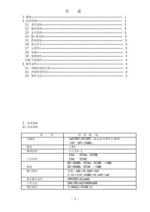
目录1. 概述------------------------------------------------------------------------------------------------------- 12. 技术性能------------------------------------------------------------------------------------------------- 2 2.1 垂直系统------------------------------------------------------------------------------------------- 2 2.2 触发系统------------------------------------------------------------------------------------------- 3 2.3 水平系统------------------------------------------------------------------------------------------- 3 2.4 X -- Y系统----------------------------------------------------------------------------------------- 3 2.5 Z轴系统-------------------------------------------------------------------------------------------- 3 2.6 校正信号-------------------------------------------------------------------------------------------- 3 2.7 示波管----------------------------------------------------------------------------------------------- 3 2.8 电源-------------------------------------------------------------------------------------------------- 3 2.9 物理特性-------------------------------------------------------------------------------------------- 32.10 环境条件-------------------------------------------------------------------------------------------- 43. 操作说明-------------------------------------------------------------------------------------------------- 4 3.1 面板控制件位置----------------------------------------------------------------------------------- 4 3.2 控制件的作用-------------------------------------------------------------------------------------- 4 3.3 操作方法-------------------------------------------------------------------------------------------- 52. 技术指标2.1 垂直系统项目技术指标灵敏度5mV/DIV--20V/DIV,按1--2--5顺序分10档(10V、20V≦5MHz)精度±3%微调范围大于2.5:1上升时间35nS ST16A、ST16B 25nS ST16C频宽DC-10MHz ST16A、ST16B (-3dB) DC-20MHz ST16C (-5dB)输入阻抗直接:1mΩ±3%,25pF±5pF经10:1探级:100MΩ±5%,16pF±2pF 最大输入电压400V(DC+AC peak)工作方式CH1,CH2,ALT,CHOP,ADD视在延时约40nS(仅ST16D有)4. 测量-------------------------------------------------------------------------------------------------------- 6 4.1 测量前的检查和调整----------------------------------------------------------------------------- 8 4.2 幅值测量-------------------------------------------------------------------------------------------- 8 4.3 时间测量-------------------------------------------------------------------------------------------- -10 4.4 电视场信号测量------------------------------------------------------------------------------------ 12 4.5 X -- Y方式的应用----------------------------------------------------------------------------------12 4.6 Z轴调制的应用----------------------------------------------------------------------------------- --121. 概述.ST16A系列示波器是便携式单通道示波器,本机垂直系统具有5mV/DIV到20V/DIV的偏转灵敏度,水平系统具有0.2S/DIV到0.1uS/DIV的扫描速度,特别友好的设计的衰减和扫描定位嵌入式安装,彻底消除普通机械开关的毛病,指示准确、永不打滑、错位!ST16B系列示波器具有触发锁定同步功能,其余指标同ST16A系列示波器。
st16材料标准
st16材料标准
摘要:
1.ST16 材料概述
2.ST16 材料的特点
3.ST16 材料的应用领域
4.ST16 材料的标准规格
5.我国对ST16 材料的研究和发展
正文:
ST16 材料是一种高强度、高韧性的钢材,广泛应用于各种工程结构和机械零部件的制造。
这种材料具有良好的耐腐蚀性能和焊接性能,使其在各种恶劣环境下都能保持稳定性能。
ST16 材料的主要特点包括高强度、高韧性、良好的耐腐蚀性能和焊接性能。
这些特点使得ST16 材料在工程应用中具有广泛的适用性。
ST16 材料主要应用于建筑结构、桥梁结构、船舶结构、石油化工设备、压力容器等领域。
ST16 材料的标准规格包括厚度、宽度、长度等尺寸参数。
在选购ST16 材料时,需要根据实际应用需求选择合适的规格。
我国对ST16 材料的研究和发展一直致力于提高其性能,扩大其应用领域。
目前,我国已经建立了完善的ST16 材料生产和检验体系,能够满足各种工程需求。
总之,ST16 材料是一种具有广泛应用和高性能的钢材。
LG16说明书1
一、概述 (2)二、操作说明 ....................................................... 错误!未定义书签。
三、安装、接线及调整......................................... 错误!未定义书签。
四、电气明细表 (7)五、电气配线图 (11)六、仪表控制器接线图箱 (12)七、外形及安装尺寸图 (13)八、控制电路图 (15)九、主电路图 (16)一、概述1. 用途本控制系统适用于我公司生产的压缩机电机的额定电压为380V,额定频率为50HZ 的Ⅱ型、Ⅲ型LG16A/F LG16DA/F LG20DA/F LG20A/F 螺杆制冷机组。
Ⅱ型、Ⅲ型LG16A/F LG16DA/F LG20A/F LG20A/F等螺杆式制冷压缩机组包括:螺杆式制冷压缩机组、带经济器螺杆式制冷压缩机组、螺杆压缩冷凝机组、带经济器螺杆压缩冷凝机组、螺杆压缩贮液机组、带经济器螺杆压缩贮液机组、螺杆冷水机组、螺杆乙醇机组、带经济器螺杆乙醇机组、螺杆盐水机组、带经济器螺杆盐水机组、螺杆碱水机组等。
注:本公司遵循超越自我,持续改进的原则,保留更改产品设计图纸,更改柜内电气元器件的选型,恕不事先通知的权利。
2. 特点本控制系统低压控制柜由交流接触器、中间继电器和时间继电器等低压电器元件组成。
机组的启动、停止等操作均采用手动控制方式。
本控制系统具有自动保护功能,当机组在运行过程中发生故障时,能自动停止机组运行,并发出声光报警并指示故障部位。
机组电气控制系统的电气原理是根据螺杆式液体冷却机组的控制系统设计的。
螺杆式压缩机组的控制系统与螺杆式液体冷却机组的控制系统基本相同,螺杆液体冷却机组的控制系统比螺杆压缩机组的控制系统多两个功能:⑴供液控制功能;⑵蒸发器出水冰点保护功能。
所以电气控制柜用于螺杆式压缩机组时,将蒸发器出水冰点的压力控制器SP4取消,低压电控柜内的端子XT2:9与XT2:11的端子短接。
- 1、下载文档前请自行甄别文档内容的完整性,平台不提供额外的编辑、内容补充、找答案等附加服务。
- 2、"仅部分预览"的文档,不可在线预览部分如存在完整性等问题,可反馈申请退款(可完整预览的文档不适用该条件!)。
- 3、如文档侵犯您的权益,请联系客服反馈,我们会尽快为您处理(人工客服工作时间:9:00-18:30)。
May 2008ST1616通道带自校正功能的容性触摸感应器概述ST16 触摸感应器可以用平均电容值作为基准检测感应点的电容变化。
它可以通过任何非导电介质来感应电容变化。
这样感应模块就可以很好的跟水和灰尘隔离。
ST16可以处理16个按键。
特点●带自校正功能的电容感应芯片●可以通过任何非导电介质感应“按键触摸”●通过外部电容调整灵敏度● I2C接口● 可以通过编程实现用户定制功能应用●替代开关●人体感应检测●玩具和互动游戏的人体界面●灯开关●替代隔膜开关●密封的键盘面板封装I2C接口定义总线的构成及信号类型I2C总线是由数据线SDA和串行时钟线SCL构成的串行总线,可发送和接收数据。
在信息的传输过程中,ST系列触摸芯片是被控器(slaver),主控MCU是主控器(master)。
SCL是串行时钟线,在通信过程中始终由主控MCU控制;SDA是数据线,接上拉电阻,主控器(master)和被控器(slaver)都可以控制SDA线,它们芯片内部是open-drain结构,发送“0”时通过芯片内部的NMOS将SDA线拉低,发送“1”时释放总线由上拉电阻将SDA线拉到高电平。
在SCL的低电平时改变状态来发送地址、数据和ACK 信号,在SCL的高电平时改变状态来发送开始和结束信号。
开始信号(start):SCL 为高电平时,SDA 由高电平向低电平跳变,开始传送数据。
结束信号(end):SCL 为低电平时,SDA 由低电平向高电平跳变,结束传送数据。
应答信号(ACK):接收数据的IC 在接收到16bit 数据后,向发送数据的IC 发出特定的低电平脉冲,表示已收到数据。
主控器向被控器发出一个信号后,等待被控器发出一个应答信号,主控器接收到应答信号后,根据实际情况作出是否继续传递信号的判断。
总线基本操作ST16采用简化的I2C 总线协议,只有读操作。
读操作的过程如下:1) 先由主控MCU 发出start 信号,主控MCU 接着送出8bit 读命令,包括7bit 地址A[6:0]和读写控制位R/WB (高电平表示读命令)。
ST16只有1个地址,地址为62h 。
主控MCU 送出的8bit 读命令应为C5h 。
2) 如果ST16正确收到读命令,就会发出低电平的ACK 信号。
如果主控MCU 没有收到ACK 信号,说明通信出现故障。
3) 接下来ST16会送出16-bit 按键信息K[15:0],表示是否按键,低平表示有按键,高电平表示无按键。
K[15:0]分别对应CIN[15:0]管脚。
4)最后主控MCU 发出NACK 信号,表示通信结束。
允许的最大波特率ST 芯片的允许最大通信速率和OSC 的频率有关。
OSC 频率值 芯片内部时钟 建议最大的波特率4M .25us 20kbps管脚说明编号名称I/O功能1 OSC I 外接电阻电容产生时钟 2NC--3 RST I 复位(低电平有效)4 CIN0 I 按键0的感应电容输入5 CIN1 I 按键1的感应电容输入6 CIN2 I 按键2的感应电容输入7 CIN3 I 按键3的感应电容输入8 CIN4 I 按键4的感应电容输入9 CIN5 I 按键5的感应电容输入10 CIN6 I 按键6的感应电容输入11 CIN7 I 按键7的感应电容输入12 GND I GND13 CIN8 I 按键8的感应电容输入14 CIN9 I 按键9的感应电容输入15 CIN10 I 按键10的感应电容输入16 CIN11 I 按键11的感应电容输入17 CIN12 I 按键12的感应电容输入18 CIN13 I 按键13的感应电容输入19 CIN14 I 按键14的感应电容输入20 CIN15 I 按键15的感应电容输入21 SCL I I2C 接口的时钟端口22 SDA I/O I2C接口的数据端口,内部上拉23 INT O 数据提示当有按键时 INT为高无按键时 INT 为低24 VDD I 电源额定值*工作温度.................................. -20°C to +85°C存储温度 ..................................... -50°C to +150°C最大工作电压............................................. 5.5V管脚的容限电压 .....................................VDD+0.3v功率损耗 .....................................80mW直流输出电流...................................................... 10.0 mA*注意:超出上述额定值可能导致芯片工作不正常并且导致芯片的永久损坏。
电气特性T A = 25℃Characteristics Symbol Condition Min Typ Max Units Operating Voltage Vdd 4.5 6.0 V Current consumption Idd VDD=5.0V, OSC=4Mhz 3.6 mA Input capacitance range Cs 10 pFdelta_Cs Cs = 5pF 0.2 pF Minimum detectivecapacitance应用线路*虚线框内的复位线路不是必须的*当RST 端口是低电平复位时,必须保证INT 端口为低电平,否则可能导致芯片永久损坏。
所以INT 端口要接下拉电阻16个检测通道都接灵敏度调整电容,可以分别调整灵敏度。
在上图的应用中只有14个检测通道可用,它们共用灵敏度调整电容。
封装型式 ( SOP-24)Dimensions In Millimeters Dimensions In Inches SymbolMin Nom Max Min Nom MaxA 2.35 2.50 2.65 0.093 0.098 0.104A1 0.10 0.20 0.30 0.004 0.008 0.012b -- 0.40 -- -- 0.016 --C -- 0.25 -- -- 0.010 --D 15.10 15.40 15.70 0.594 0.606 0.618E 7.35 7.50 7.65 0.289 0.295 0.301e -- 1.27 -- -- 0.050 --H 10.15 10.45 10.75 0.400 0.411 0.423K -- 0.50 -- -- 0.020 -- L 0.60 0.80 1.00 0.024 0.031 0.039 α0°-- 8°0°-- 8°β-- 45°-- -- 45°--附录:读取ST16芯片的示例程序,用8051汇编语言编写ReadKey:;;先发送addr寄存器的内容C5H,做为8bit读命令mov bitnum, #8clr sda ;;发送start信号lcall Nop10 ;;延时ReadKey_1:clr sclmov a, addrrlc amov addr, amov sda, clcall Nop10setb scllcall Nop10djnz bitnum, ReadKey_1;;发送8bit读命令结束,开始读是否有ACK信号clr scllcall Nop10setb scllcall Nop10lcall Nop10mov c, sdajnc ReadKey_2LCALL Error ;;没有收到ACK信号,执行出错处理程序ReadKey_2:;;开始读ST16送出的8bit按键数据,结果存到keyh寄存器mov bitnum, #8ReadKey_3:clr scllcall Nop10setb scllcall Nop10mov c, sdamov a, keyhrlc amov keyh, adjnz bitnum, ReadKey_3;;滑条数据接收完毕;; 开始读ST16送出的8bit按键数据,结果存到keyl寄存器mov bitnum, #8ReadKey_4:clr scllcall Nop10setb scllcall Nop10mov c, sdamov a, keylrlc amov keyl, aReadKey_4bitnum,djnz;;按键数据接收完毕clr scllcall Nop10setb scllcall Nop10clr scllcall Nop10setb sclret。