UM66TXXL-T92-R中文资料
EC92 User Manual 电机 使用说明书

P05 Attentions P10 P11 Troubleshooti Quick cse _g u ide P04technical p aramete,PO7EC92 Electrostatic Air PurifierP08Speed,_Wlnd speed』wlnd speed ls dlvlded lnto three $talls lt /, ! 勺'as a comsponding wind 5peed,con on the contml panel宅?夕C.gn..,r,dn8加,3d迁n8galfe,gn六m忒心ggh伈”e市,l比n叫$h.2nbucn rdmg`2,汕"tr,noh”e ot9:wg比2hcssn-9勺on心吐.总rob39er�它芒tne'呤尸mkg旧气nCPhdty"戏AeP5cg_htd nhnllt.DnhACUV 芯忑芯芯aloto匹h心1佃nl伍,屈,“'心叩.“四chReset三千a;22二二.0:::立了二二芯°:,·肋飞:二”:车2aho n soquo n cat`O沁“如心.旧庙ou1中heo ld,hmI',/仓,J/夕J3�y芍i忽,/f勾气j'倡冒三,以户、立=n匀罢亏王仁==;_,purify functionI ntelligent ai「purifierfilte『S+8sf tBge pu『ification;::p::三::::三n ep;勹::,c.『e:r”:三:e;f::m5.:.二;i.h l;:「f二:::;u;?'::“二d c a nhepa亡:二,.二“二.二.。
二二°C:二:2:;二二.::::,二勹。
二二:二'.6.p.尸"'"叩r l n,h..凡m喊n l y知tho p心沁9`d P M 2.5. l t h邸·一毗中ngL中^`.l ll a nd l m l l l l l.ca『bon::三三芒芒:'s:0:0,::0:',三三三'",三二三了p:::三:二二can bo中".,...,..芒5三三立:芷二?忒u":二::二。
lm7812中文资料_数据手册_参数
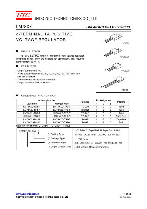
LM78XX
LINEAR INTEGRATED CIRCUIT
3-TERMINAL 1A POSITIVE VOLTAGE REGULATOR
1
TO-220
DESCRIPTION
The UTC LM78XX family is monolithic fixed voltage regulator integrated circuit. They are suitable for applications that required supply current up to 1 A.
2.0
V
70 mV
35 mV
70 mV
70 mV
8.0 mA
1.0 mA
0.5 mA
50
μV
-0.8
mV/°C
59 75
dB
1.7
A
UNISONIC TECHNOLOGIES CO., LTD
5 of 13
QW-R101-006.U
LM78XX
LINEAR INTEGRATED CIRCUIT
PARAMETER
SYMBOL
RATING
UNIT
Input voltage
VOUT=5~18V VOUT=24V
VIN
35
V
40
V
Output Current Power Dissipation
IOUT
1
A
PD
Internally Limited
W
Operating Junction Temperature Storage Temperature
模组说明书:Modicon M258 TM258LF66DT4L
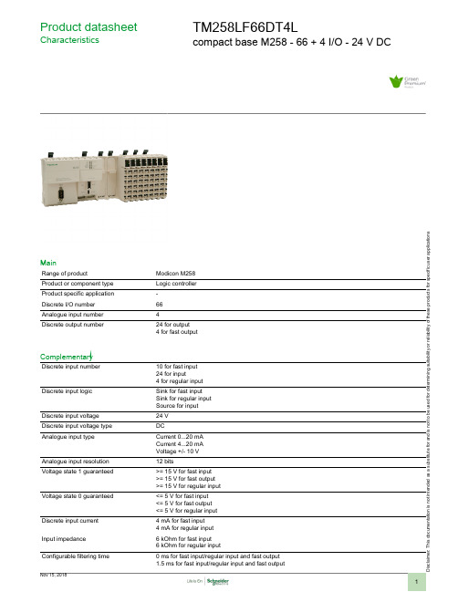
i s c la i me r : T h i s d o c u m e n t a t i o n i s n o t i n t e n d e d a s a s u b s t i t u t ef o r a n d i s n o t t o b e u s e d f o r d e t e r m i n i ng s u i t a b i l i t y o r r e l i a b i l i t y o f th e s e p r o d u c t s f o r s p e ci f i c u s e r a p p l i c a t i o n sProduct datasheetCharacteristicsTM258LF66DT4Lcompact base M258 - 66 + 4 I/O - 24 V DCMainRange of productModicon M258Product or component type Logic controller Product specific application -Discrete I/O number 66Analogue input number 4Discrete output number24 for output 4 for fast outputComplementaryDiscrete input number10 for fast input 24 for input4 for regular input Discrete input logicSink for fast input Sink for regular input Source for input Discrete input voltage 24 V Discrete input voltage type DCAnalogue input typeCurrent 0...20 mA Current 4...20 mA Voltage +/- 10 V Analogue input resolution 12 bitsVoltage state 1 guaranteed>= 15 V for fast input >= 15 V for fast output >= 15 V for regular input Voltage state 0 guaranteed<= 5 V for fast input <= 5 V for fast output <= 5 V for regular input Discrete input current 4 mA for fast input 4 mA for regular input Input impedance 6 kOhm for fast input 6 kOhm for regular inputConfigurable filtering time0 ms for fast input/regular input and fast output 1.5 ms for fast input/regular input and fast output12 ms for fast input/regular input and fast output4 ms for fast input/regular input and fast outputAnti bounce filtering 2 µs...4 ms (configurable) fast input/regular input and fast outputCable distance between devices30 m for fast input30 m for fast output30 m for regular input500 Vrms ACIsolation between channels andinternal logicIsolation between channels NoneDiscrete output logic SourceDiscrete output voltage24 V DCOutput voltage limits19.2...28.8 VDiscrete output current 4 mA for fast output[Us] rated supply voltage24 V DC for embedded expert modules power24 V DC for I/O power segment24 V DC for main supplySupply voltage limits20.4...28.8 V[In] rated current0.04 A for embedded expert modules power0.31 A for main supply10 A for I/O power segmentPeak current<= 100 kA during <= 70 s main supply<= 25 kA during <= 500 s I/O power segment<= 50 kA during <= 150 s embedded expert modules power<= 1.2 kA during > 70 s main supplyPower consumption in W<= 18.11 WExecution time per instruction22 ns : BooleanMemory description Flash 128 MBInternal RAM 64 MBRealtime clock With user calibration realtime clock, drift: <= 6 s/monthWithout any user calibration realtime clock, drift: < 30 s/month at 25 °CData backed up Variables of type retain and retain persistent CR2477M Renata, 1.5 years autonomy Integrated connection type 1 CANopen male SUB-D 9, CANopen master1 isolated serial link female RJ45, Ethernet Modbus TCP/IP slave (10BASE-T/100BASE-TX)2 free slots PCI1 isolated serial link female RJ45, Modbus master/slave RTU/ASCII or character mode ASCII(RS232/RS485), 300...115200 bps1 isolated serial link mini B USB, 480 Mbit/s1 isolated serial link USB type A, 480 Mbit/sTransmission rate125 kbit/s for bus length of 500 m, CANopen250 kbit/s for bus length of 250 m, CANopen50 kbit/s for bus length of 1000 m, CANopen500 kbit/s for bus length of 100 m, CANopen10 kbit/s for bus length of 5000 m, CANopen1000 kbit/s for bus length of 4 m, CANopen20 kbit/s for bus length of 2500 m, CANopen800 kbit/s for bus length of 25 m, CANopenCounting input number8 counting input(s) 200 kHzLocal signalling 1 LED per channel for I/O state1 LED for CAN0 STS1 LED for MBS COM1 LED green/red for APP01 LED green/red for APP11 LED green/red for Eth NS (Ethernet network status)1 LED green/red for Eth ST (Ethernet status)1 LED green/red for RUN/MS (module status)1 LED green/red for USB host1 LED green/yellow for Eth LA (Ethernet activity)1 LED red for BATT (battery status)Marking CEMounting support Symmetrical DIN railWidth262.5 mmHeight99 mmDepth85 mmProduct weight0.8 kgEnvironmentStandardsCSA C22.2 No 142IEC 61131-2UL 508CSA C22.2 No 213Product certificationsCSA C-Tick cULus GOST-RAmbient air temperature for operation0...55 °C without derating factor horizontal installation 0...60 °C with derating factor horizontal installation 0...50 °C vertical installation Ambient air temperature for storage -25...70 °CRelative humidity 5...95 % without condensation IP degree of protection IP20 conforming to IEC 61131-2Pollution degree 2 conforming to IEC 60664Operating altitude 0...2000 m Storage altitude 0...3000 mVibration resistance 1 gn 8.4...150 Hz DIN rail 3.5 mm 5...8.4 Hz DIN rail Shock resistance15 gn for 11 msResistance to electrostatic discharge 4 kV on contact conforming to EN/IEC 61000-4-28 kV in air conforming to EN/IEC 61000-4-2Resistance to electromagnetic fields 1 V/m 2...2.7 GHz conforming to EN/IEC 61000-4-310 V/m 80...2000 MHz conforming to EN/IEC 61000-4-3Resistance to fast transients1 kV I/O conforming to EN/IEC 61000-4-41 kV shielded cable conforming to EN/IEC 61000-4-42 kV power lines conforming to EN/IEC 61000-4-4Surge withstand0.5 kV differential mode conforming to EN/IEC 61000-4-51 kV common mode conforming to EN/IEC 61000-4-5Disturbance radiated/conductedCISPR 11Offer SustainabilitySustainable offer status Green Premium productRoHS (date code: YYWW)Compliant - since 1039 - Schneider Electric declaration of conformity Schneider Electric declaration of conformity REAChReference not containing SVHC above the threshold Reference not containing SVHC above the threshold Product environmental profile AvailableProduct environmental Product end of life instructionsAvailableEnd of life manualContractual warrantyWarranty period18 monthsDimensions DrawingsControllerDimensionsTM5 System Wiring RecommendationsWire Sizes to Use with Removable Spring Terminal BlocksExternal Power SuppliesWiring Diagram of the Controller Power Distribution Module(1)Internal electronics(2)24 Vdc I/O power segment integrated into the bus bases (3)PS1/PS2: External isolated SELV power supply 24 Vdc (4)External fuse, Type T slow-blow, 3 A 250 V (5)External fuse, Type T slow-blow, 2 A 250 V(6)External fuse, Type T slow-blow, 10 A max., 250 V。
SL2.2S规格书,usb HUB大全,替换FE1.1S,GL850,GL852,PL2586
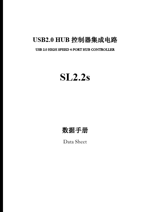
USB2.0 HUB控制器集成电路USB 2.0 HIGH SPEED 4-PORT HUB CONTROLLERSL2.2s数据手册Data Sheet内容目录第一章管脚分配 (3)1.1 SL2.2S管脚图 (3)1.2 SL2.2S管脚定义 (3)第二章 功能叙述 (5)2.1综述 (5)2.2指示灯 (5)2.2.1单灯方案 (5)2.2.2多灯方案 (6)2.2.3 LED指示定义 (6)2.3过流保护 (6)2.4充电支持 (6)2.5I2C接口 (7)2.6EEPROM设置 (7)第三章电气特性 (8)3.1极限工作条件 (8)3.2工作范围 (8)3.3直流电特性 (8)3.4HS/FS/LS电气特性 (8)3.5ESD特性 (8)附录一封装 (9)表格目录表格1: 端口LED定义 (6)表格 2 : ACTIVE LED定义 (6)表格3:EEPROM数据结构定义 (7)表格4: 最大额定值 (8)表格5: 工作范围 (8)表格6: 直流电特性 (8)插图目录图1:SSOP28 管脚图 (3)图2:单灯方案配置 (5)图3: 5灯方案配置 ............................................................................... (6)图 4:附录 封装图 ................................................................................... .9第一章管脚分配1.1SL2.2s管脚图图1:SSOP28 管脚图1.2SL2.2s管脚定义管脚名称28Die IO类型定义Pin#VSS 1 P 芯片地XOUT 2 O晶振PAD XIN 3 IDM4 4 B下行口4的USB信号DP4 5 BDM3 6 B下行口3的USB信号DP3 7 BDM2 8 B下行口2的USB信号DP2 9 BDM1 10 B下行口1的USB信号DP1 11 BVDD18 12 P 模拟1.8vVDD33 13 P 模拟3.3v - 14 NCUDM 15 B上行口的USB信号UDP 16 BRESET_N 17 I,Pu 芯片外部复位输入- 18 NCPSELF 19 I,Pu 高为自供电,低为总线供电VDD5 20 P 5v输入VDD33 21 P 3.3v输出DRV 22 B,Pu 点灯驱动信号LED1 23 B,Pu 点灯驱动信号LED2 24 B,Pu 点灯驱动信号PWRN 25 B,Pu 下行口电源输出控制,低有效OVCRN/SDA 26 B,PuI2C SDA数据线,内部上拉;芯片初始化完成后作为过流保护输入脚,低有效SCL 27 B,Pu I2C SCL时钟输出VDD18 28 P 数字1.8v注释:O,输出;I 输入;B 双向;P 电源/接地;Pu 上拉;Pd 下拉;NC 悬空;第二章 功能叙述2.1综述SL2.2s 是一颗高集成度,高性能,低功耗的USB2.0集线器主控芯片;该芯片采用STT 技术,单电源供电方式,芯片供电电压为5v , 内部集成5V 转3.3V,只需在外部电源添加滤波电容;芯片自带复位电路,低功耗技术让他更加出众。
乐希乌姆LXM05AD17M2动力servo驱动器数据表说明书
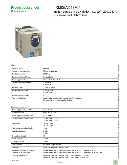
Product data sheetCharacteristicsLXM05AD17M2motion servo drive LXM05A - 1.2 kW - 200..240 V - 1-phase - with EMC filterMainRange of productLexium 05Product or component type Motion servo drive Component name LXM05A Network number of phases Single phasePower supply voltage 200...240 V - 15...10 %Continuous output current 7 A at 8 kHz 8 A at 4 kHz Nominal power 1.2 kW at 4 kHz Discrete input number 2 safety input(s)4 logic input(s)Analogue input number 2Type of polarizationIntegrated and switchable impedances for CANopen No polarization impedances for ModbusComplementaryPower supply voltage limits 170...264 V Supply frequency50/60 Hz - 5...5 %Power supply frequency limits 47.5...63 Hz Transient RMS output current 11 A at 8 kHz for 3 s 12 A at 4 kHz for 3 s Line current10.5 A at 240 V 12.7 A at 200 V Maximum prospective line Isc 1 kA Switching frequency 8 kHz 4 kHz Overvoltage category III Inrush current < 60 A Leakage current < 30 mAOutput voltage <= power supply voltageInsulationElectrical between power and controlRecommended type of cable for mounting in an enclosure Without mounting kit :single-strand IEC cable at 45 °C, copper 70 °C PVCWithout mounting kit :single-strand IEC cable at 45 °C, copper 90 °C XLPE/EPR Electrical connectionTerminal, clamping capacity: 6 mm² (AWG 10)PA/+, PBI, PBe Terminal, clamping capacity: 6 mm² (AWG 10)R/L1, S/L2, T/L3D i s c l a i m e r : T h i s d o c u m e n t a t i o n i s n o t i n t e n d e d a s a s u b s t i t u t e f o r a n d i s n o t t o b e u s e d f o r d e t e r m i n i n g s u i t a b i l i t y o r r e l i a b i l i t y o f t h e s e p r o d u c t s f o r s p e c i f i c u s e r a p p l i c a t i o n sTightening torque 1.2 N.m (PA/+, PBI, PBe)1.2 N.m (R/L1, S/L2, T/L3)Discrete input type Logic input(s) (LI1, LI2, LI3, LI4)Safety input(s) (PWRR_A, PWRR_B)Sampling duration0.25 ms (ANA1+/ANA1-, ANA2+/ANA2-), analog input(s)0.25 ms (LI1, LI2, LI3, LI4), discrete input(s)Discrete input voltage24 V DC (logic input(s))24 V DC (safety input(s))Discrete input logic Negative (LI1, LI2, LI3, LI4) state 0: > 19 V, state 1: < 9 V conforming to EN/IEC 61131-2 type 1Positive logic (compliment of PWRR_A, compliment of PWRR_B) state 0: < 5 V, state 1: > 15 Vconforming to EN/IEC 61131-2 type 1Positive logic (LI1, LI2, LI3, LI4) state 0: < 5 V, state 1: > 15 V conforming to EN/IEC 61131-2 type 1 Response time<= 10 msDiscrete output number2Discrete output type Logic output(s) (LO1, LO2) 24 V DCDiscrete output voltage<= 30 V DCDiscrete output logic Negative (LO1, LO2) conforming to EN/IEC 61131-2Positive (LO1, LO2) conforming to EN/IEC 61131-2Contact bounce time 1 ms (LI1 (I4)Braking current50 mAResponse time on output 1 ms (LO1, LO2) for discrete output(s)Absolute accuracy error< +/- 1 % 25 °C< +/- 2 % over operating temperature rangeLinearity error< +/- 0.5 %Analogue input type Analog input (ANA1+/ANA1-, ANA2+/ANA2-) differential +/- 10 V, >= 10000 Ohm, 14 bits Protection type Against reverse polarity for inputs signalAgainst short-circuits for outputs signalSafety function PWR protection of the machine stop and/or prevent unintended operation of the servo motorconforming to IEC/EN 61800-5-2PWR protection of the machine stop and/or prevent unintended operation of the servo motorconforming to ISO 13849-1 level dPWR protection of the system process stop and/or prevent unintended operation of the servo motorconforming to EN/IEC 61508 level SIL2PWR protection of the system process stop and/or prevent unintended operation of the servo motorconforming to IEC/EN 61800-5-2Communication port protocol ModbusCANopenCANopen MotionbusConnector type RJ45 (labelled CN4) for CANopen, CANopen MotionbusRJ45 (labelled CN4) for ModbusSpring terminals (labelled CN1) for CANopen, CANopen MotionbusMethod of access Slave for CANopen, CANopen MotionbusPhysical interface2-wire RS485 multidrop ModbusRS422 for 1 A/B input(s), <= 400 kHzRS422 for 1 CW/CCW input(s), <= 400 kHzRS422 for 1 ESIM output input(s), <= 400 kHzRS422 for 1 P/D input(s), <= 400 kHzTransmission rate50 kbps, 125 kbps, 250 kbps, 500 kbps, 1 Mbps for CANopen, CANopen Motionbus9600, 19200, 38400 bps for ModbusData format8 bits, no parity, 1 or 2 stop Modbus8 bits, odd or even parity, 1 stop ModbusNumber of addresses 1...247 addresses for Modbus1...127 addresses for CANopen, CANopen MotionbusCommunication service 1 receive SDO + 1 transmit SDO for CANopen Motionbus2 PDO for CANopen Motionbus2 receive SDO + 2 transmit SDO for CANopen3 PDO + 1 configurable mapping PDO for CANopenCiA DSP 402 profile for CANopenCiA DSP 402 profile for CANopen MotionbusCommunication monitoring for ModbusDiagnostics (08) for ModbusRead device identification (43) for ModbusRead holding registers (03) for ModbusRead/write multiple registers (23) for ModbusWrite multiple registers (16) for ModbusWrite single register (06) for ModbusDiagnostics 1 LED red signalling drive voltage1 LED signalling error for CANopen1 LED signalling RUN for CANopenSignalling function Display of faults on integrated 7-segment display terminalMax nodes number31 for ModbusInput resistance 5 kOhmMarking CEType of cooling FanOperating position Vertical +/- 10 degreeProduct weight 1.4 kgEnvironmentEMC filter IntegratedElectromagnetic compatibility 1.2/50 µs - 8/20 µs surge immunity test level 3 conforming to IEC 61000-4-5Electrical fast transient/burst immunity test level 4 conforming to IEC 61000-4-4Electrostatic discharge immunity test level 3 conforming to IEC 61000-4-2Radiated radio-frequency electromagnetic field immunity test level 3 conforming to IEC 61000-4-3 Standards EN/IEC 50178EN/IEC 61800-5-1EN/IEC 61800-3Product certifications CULULIP degree of protection IP20 on upper part with protective cover removed conforming to EN/IEC 60529IP20 on upper part with protective cover removed conforming to EN/IEC 61800-5-1IP41 on upper part with protective cover in place conforming to EN/IEC 60529IP41 on upper part with protective cover in place conforming to EN/IEC 61800-5-1Vibration resistance 1.5 mm peak to peak (f = 3...13 Hz) conforming to EN/IEC 60068-2-61 gn (f = 13...150 Hz) conforming to EN/IEC 60068-2-6Shock resistance15 gn (duration = 11 ms) conforming to EN/IEC 60028-2-27Pollution degree 2 conforming to EN/IEC 61800-5-1Environmental characteristic Classes 3C1 conforming to IEC 60721-3-3Relative humidity Class 3K3 (5 to 93 %) without condensation conforming to IEC 60721-3-3Ambient air temperature for operation0...50 °CAmbient air temperature for storage-25...70 °COperating altitude<= 1000 m without derating> 1000...2000 m with conditionsContractual warrantyWarranty period18 months。
镀镍测厚仪

沧州欧谱
麦考特G6测厚仪
Mikrotest 磁性测厚仪符合下列国际标准:DIN 50 981,50 982;ASTM 8499,E367,D1186,B530,G12;BS5411;DIN EN ISO 2178,2361
八、检查精确度
测厚仪装有磁钢,在正常使用时是不会发生变化的。通常只 需偶尔或在怀疑读数的正确性时去测量厚度标准,进行调整。对 于这种测量可采用EPK 公司的厚度标准件。如图(6)所示,标 准板厚度表如表二所示。
-5-
沧州欧谱
麦考特G6测厚仪
图6
E01
◆ 测厚仪放置错误
◆ 在被表面正确放置测厚仪进行测量
◆ 基体是永久磁钢 E02 错误的测量
操作错误
◆ 消除基体磁性 重新测量
E04 ◆ 覆层厚度高于测量上限 E05 ◆ 测厚仪没有正确在放在表面上测量
◆ 选择合适的仪器 ◆ 在被表面正确放置测厚仪进行测量
◆ 基体没有磁性 E06 电池电量低 E00
十二、本公司的其它测量设备
◆ OU2100便携式里氏硬度计; ◆ OU1600超声波测厚仪; ◆ OU3500涂镀层测厚仪; ◆ OU4000附着力检测仪; ◆ OU4200油漆光泽度仪; ◆ OU5100超声波探伤仪; 您如果对以上产品感兴趣,请向我们索取详细资料。
十三、附录
1、实际使用中的几个问题 由于磁吸力或测厚仪经过校准后,在使用中不能再变动,所
-6-
沧州欧谱
麦考特G6测厚仪
十、备选件
EPK 针对Mikrotest 测厚仪可提供以下备选件: ◆ 厚度标准板,用于检验测厚仪; ◆ 布背包,可在高空作业时使用; ◆ 湿膜测厚仪,用来测量湿涂层。
高科特实际产品说明书
4
Specifications are subject to change without notice (21.06.2021)
Solid State Relays Accessories, Screw Kits Types SRWKIT…
Ordering Key
Screw Kit Screw size Screw length
0.5 Nm -20° to + 70°C [-4 to +158°F] -40° to + 100°C [-40° to +212°F] DIN EN 50022, 50035
DIN Adaptor for 1-phase SSRs
DIN rail adaptor module for mounting the 1-phase SSR series RA, RD, RM, RS and RAM directly on DIN rail.
Type
UL style 2547 UL style 2464 UL style 2464 UL style 2464 UL style 2464 UL style 2464
Cable size
0.14mm2 0.14mm2 0.14mm2 0.25mm2 0.14mm2 0.14mm2
Termination
- Width x Height x Thickness = 35 x 43 x 0.25 mm
- Packing qty. 50 pcs.
RZHT
- Graphite thermal pad for RZ3 series with adhesive on one side
- Width x Height x Thickness = 70 x 77 x 0.25 mm
SICK UM系列超声波传感器选型手册(中文版)
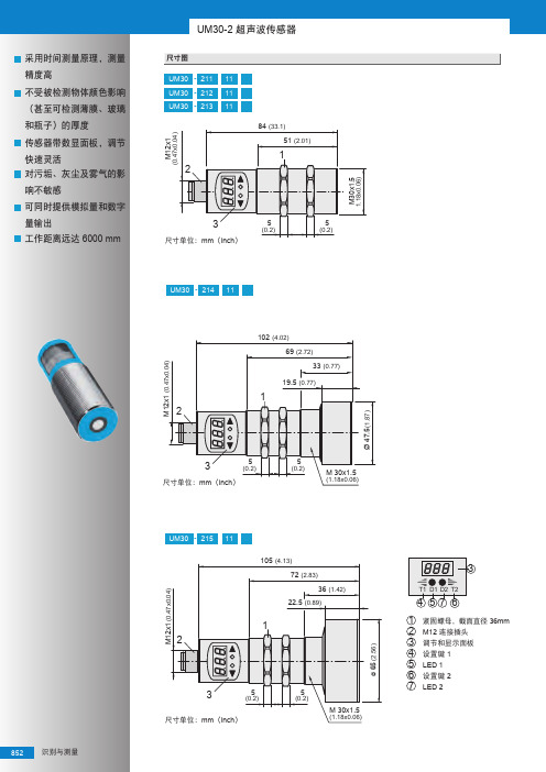
200 ... 1300 mm (2000)
订货号
6037537 6037666 6036923 6037671 6037676 6036918
输入或输出
PNP PNP PNP NPN NPN N/A
110 ms
6 Hz
输出与接口 1) 2) 3)
Q1 Q1, Q2 Q1, 4 … 20 mA, 0 … 10 V Q1 Q1, Q2 4 … 20 mA, 0 … 10 V
尺寸单位:mm(英寸)
型号 DOL-1205-G02MC DOL-1205-G05MC DOL-1205-G10MC
44 (1.73) 1.5 (0.06)
订货号 6025906 6025907 6025908
5/灰
3/蓝
4/黑
2/白
1/棕
尺寸单位:mm(英寸)
型号 DOL-1205-G02MC DOL-1205-G05MC DOL-1205-G10MC
尺寸单位:mm (inch)
识别与测量 855
14.5 (0.57) M12x1
(0.47x0.04)
型号 DOL-1205-W02M DOL-1205-W05M DOL-1205-W10M
26.5 (1.04) 12 (0.47) 1.5 (0.06)
UM30-2 超声波传感器
订货号 6008900 6008869 6010542
400
UM30 - 215 11
200
100
0
3
100
200
UM30-21211_ 350 mm
[mm] 100
200
300
1
400
500
600
UM66T05LK-T92-R中文资料

UNISONIC TECHNOLOGIES CO., LTDUM66TXXL CMOS ICMELODY INTEGRATED CIRCUITDESCRIPTIONThe UTC UM66TXXL series are CMOS LSI designed for usingin door bell, telephone and toy application. It is an on-chip ROM programmed for musical performance. Produced by CMOS technology, the device results in very low power consumption. Since the UTC UM66TXXL series include oscillation circuits a compact melody module can be constructed with only a few additional components.FEATURES*64-Note Rom memory*1.5V ~ 4.5V power supply and low power consumption *Dynamic speaker can be driven with external NPNtransistor*OSC resistor hold mode*Power on reset: melody begins from the first note *Built in level hold mode*Pb-free plating product number: UM66TxxLKORDERING INFORMATIONOrder Number Pin AssignmentNormal Lead Free Plating Package 1 2 3PackingUM66TxxL-T92-B UM66TxxLK-T92-B TO-92 V SS V DD O/P Tape Box UM66TxxL-T92-K UM66TxxLK-T92-K TO-92 V SS V DD O/P Bulk UM66TxxL-T92-R UM66TxxLK-T92-R TO-92 V SS V DD O/P Tape ReelSONG SERIES LISTP/N SONG NAMEUTC UM66T05L Home Sweet Home UTC UM66T08L Happy Birthday UTC UM66T11L Love Me Tender UTC UM66T19L For Alice UTC UM66T32L COO COO waltzABSOLUTE MAXIMUM RATINGS (Operating temperature range applies unless otherwise specified.)UNIT PARAMETER SYMBOL RATINGSDC Supply Voltage V DD 1.5 ~ 4.5 VOperating Temperature T OPR-10 ~ +60 °CStorage Temperature T STG-55 ~ +125 °CNotes: Stress above those listed under absolute maximum ratings may cause permanent damage to the device.These are stress ratings only. Functional operations of this device at these or any other conditions abovethose indicated in the operational section of this specification is not implied and exposure to absolutemaximum ratings conditions for extended periods may affect device reliablyELECTRICAL CHARACTERISTICS (Vss=0V, Fosc=65536Hz, T J=25℃, unless otherwise specified)FUNCTIONAL DESCRIPTIONOSCILLATOR CIRCUITThe oscillator frequency is used as a time for tone and beat generators. Its accuracy affects the quality of the music.TONE GENERATORTone Frequencies are oscillator frequencies-M, where m is any even number from 64 to 256. Within a melody 14C scales can be selected including Pause code and End code. The tone generator is a programmed divider, The Range of Scales is from “C4” to “C6” and range of frequency varies from 258Hz to 23768Hz.RHYTHM GENERATORThe rhythm generator is also programmed dividers. It contain 15 available rhythms asfollows:1/4,1/2,3/4,1,1-1/4,1-1/2,1-/3/4,2,2-1/4,2-1/2,2-/3/4,3,3-1/4,3-1/2,3-/3/4.Four rhythms can be selected from these.MELODY ROMThe Mask Rom can memorize 64 notes with 6 bit.4 bits are used for controlling the scale code and 2 bits are used for controlling the rhythm code.TEMPO GENERATORThere are 15 available tempos in the UTC UM66T series. The 15 tempos are:128,137,148,160,175,192,213, 240 , 274, 320,480,640,960,1920 J/minute.APPLICATION CIRCUITSFig.1Fig.2。
ALTIVAR 66 调速电子变压器用户手册说明书

Bulletin No. 30072-450-73May 2002Raleigh, NC, USAALTIVAR ® 66Addendum to VD0C06S304E ATV66 Repair PartsAddendumRetain for future use.This Addendum replaces Appendix A of instruction bulletin VD0C06S304E, ALTIVAR 66® Adjustable Speed Drive Controllers for Asynchronous Motors User’s Manual, Constant and Variable T orque: 1 to 400 hp, 460 V and 1 to 50 hp, 230 V , Receiving, Installation, and Start-up . This addendum contains revised repair parts information.Replacement of repair parts requires the use of special tools and installation procedures not included with the repair parts kits. Before replacing any repair part, consult the ALTIVAR 66 Drive Controller Service and Troubleshooting Manual , bulletin number VD0C06S701 (1–75 hp, 100 hp VT) orVD0C06S702 (100–350 hp, 125–400 hp VT). These manuals can beordered from your local Square D distributor. Repair parts must be replaced only by qualified electrical personnel familiar with the service and troubleshooting manual.When ordering repair parts for the A TV66C10N4 to A TV66C19N4 drive controllers, check the drive controller serial number and follow theseguidelines. Refer to pages 3–5 of bulletin VD0C06S304E for assistance in finding the drive controller serial number.•If the serial number has a “1” as the seventh digit, select repair parts from the repair parts list beginning on page 2 of this addendum. All drivecontrollers shipped on or after June 1, 1998 have a “1” as the seventh digit of the serial number. See Figure 2 on page 2 for illustrations of these controllers. •If the serial number does not have a “1” as the seventh digit, consult bulletin VD0C06S702 for repair parts. These are drive controllers that shipped on or before May 31, 1998. They are illustrated in Figure e the repair parts list beginning on page 2 of this addendum for all other drive controller models (A TV66U41N4 to A TV66D79N4, A TV66U41M2 to A TV66D46M2, and A TV66C23N4 to A TV66C31N4).Figure 1:ATV66C10N4–C19N4: Shipped On or Before May 31, 1998INTRODUCTIONSELECTING REPAIR PARTS FOR ATV66C10N4 TO ATV66C19N4 DRIVECONTROLLERSFor controllers like this, select repair parts from bulletin VD0C06S702, Service and Troubleshooting Manual (100–350 hp, 125–400 hp VT).Addendum to VD0C06S304E Bulletin No. 30072-450-73ATV66 Repair Parts May 2002Figure 2:ATV66C10N4–C19N4: Shipped On or After June 1, 1998For controllers like these, select repair parts from the following Repair Parts List.Repair Parts ListDescriptionDrive Controller Part No.NoteALTIVAR 66 Adjustable Speed Drive Controllers Service and Troubleshooting ManualATV66 1–75 hp,100 hp VT VD0C06S701ATV66 100 hp CT, 125–400 hpVD0C06S702Control Kit — 460 VATV66U41N4 to D79N4ATV66C10N4 to C31N4VX4A66CK1VX4A66CK2Matched keypad display and control basket with latest firmwareControl Kit — 208/230 VATV66U41M2 to D46M2 (except ATV66D23M2S264U)VX4A66CK1 ATV66D23M2S264UVX4A66CK1S260Keypad DisplayRefer to the section “Identifying the FirmwareVersion” in Chapter 4 of bulletin VD0C06S304E and determine the firmware version of your drive controller.For drive controllers with firmware level 3.0 andlaterATV66 all sizesVW3A66206UFor drive controllers with firmware version earlier than 3.0Order the control kit listed above that is appropriate for your drive controller.Removable Control Terminal StripsATV66 all sizesVZ3N006J1, J12, and J13 on control basketBulletin No. 30072-450-73Addendum to VD0C06S304EMay 2002ATV66 Repair PartsPower Board — 460 VATV66U41N4VX5A66U41N4Includes IGBT block, rectifier diode, heatsink, and fan ATV66U54N4VX5A66U54N4ATV66U72N4VX5A66U72N4ATV66U90N4VX5A66U90N4ATV66D12N4VX5A66D12N4ATV66D16N4VX5A66D16N4Power board onlyATV66D23N4VX5A66D23N4ATV66D33N4VX5A66D33N4ATV66D46N4VX5A66D46N4ATV66D54N4VX5A66D54N4ATV66D64N4VX5A66D64N4ATV66D79N4VX5A66D79N4ATV66C10N4 VX5A661C10N4ATV66C13N4VX5A661C13N4ATV66C15N4VX5A661C15N4ATV66C19N4 VX5A661C19N4ATV66C23N4VX5A661C23N4ATV66C28N4VX5A661C28N4ATV66C31N4VX5A661C31N4Power Board — 208/230 VATV66U41M2VX5A662U41M2Includes IGBT block and rectifier diode ATV66U72M2VX5A662U72M2ATV66U90M2VX5A662U90M2ATV66D12M2VX5A66D12M2Power board onlyATV66D16M2VX5A66D16M2Power Board and Gate Driver Board — 208/230 VATV66D23M2VX5A66D234M2Matched set ATV66D33M2VX5A66D335M2ATV66D46M2VX5A66D466M2Gate Driver Board — 460 VATV66D16N4VX5A66103Gate driver board only ATV66D23N4VX5A66104ATV66D33N4VX5A66105ATV66D46N4VX5A66106ATV66D54N4VX5A66107ATV66D64N4VX5A66108ATV66D79N4VX5A66109Gate Driver Board — 208/230 V ATV66D12M2VX5A66112ATV66D16M2VX5A66113Inverter IGBT — 460 V[1] For units with a serial number starting with “6W”, or for units with a serial number starting with “86” and a date code of 0216 or earlier. [2]For units with a serial number starting with “86”and a date code of 0217 or later.Refer to pages 3–5 of bulletin VD0C06S304E for assistance in finding the serial number and date code.ATV66D16N4VZ3lM2050M1201 1 dual IGBT block ATV66D23N4VZ3lM2075M1201ATV66D33N4VZ3lM2100M1201ATV66D46N4, D54N4VZ3lM2150M1201ATV66D64N4VZ3lM2200M1201ATV66D79N4 [1]VZ3IM2300M1201ATV66D79N4 [2]VZ3IM2200M1202ATV66C10N4VZ3IM2300M1202 2 IGBT blocks, 2 snubber boards, 2 gate driver boards, 1 clamp moduleATV66C13N4 to C19N4VZ3IM2400M1202ATV66C23N4, C28N4VZ3IM1400M1207 4 IGBT blocks, 2 snubber boards, 2 gate driver boards ATV66C31N4VZ3IM1500M1207Repair Parts List (Continued)DescriptionDrive Controller Part No.NoteAddendum to VD0C06S304E Bulletin No. 30072-450-73ATV66 Repair Parts May 2002Inverter IGBT — 208/230 VATV66D12M2VZ3IM2075M0601 1 dual IGBT blockATV66D16M2VZ3IM2100M0601ATV66D23M2VZ3IM2150M0601ATV66D33M2VZ3IM2200M0601ATV66D46M2VZ3IM2300M0601Inverter IGBT Clamp Capacitor ATV66C23N4 to C31N4VY1ADC610 1 capacitorDynamic Braking IGBT — 460 VATV66D16N4, D23N4VZ3IM1025M1001 1 IGBT BlockATV66D33N4, D46N4VZ3IM2050M1201ATV66D54N4VZ3IM2100M1201ATV66D64N4, D79N4VZ3IM2150M1201ATV66C10N4 to C19N4VZ3IM1300M1202 1 IGBT block, 1 diode block,1 snubber board, 1 gate driver board ATV66C23N4VZ3IM1400M1208ATV66C28N4, C31N4VZ3IM1300M1208 2 IGBT blocks, 2 diode blocks,2 snubber boards, 1 gate driver boardDynamic Braking IGBT — 208/230 VATV66D12M2, D16M2VZ3IM1060M0601 1 IGBT blockATV66D23M2VZ3IM2075M0601ATV66D33M2VZ3IM2100M0601ATV66D46M2VZ3IM2150M0601Dynamic Braking Clamp Capacitor ATV66C10N4 to C19N4VY1ADC616 1 capacitorATV66C23N4 to C31N4VY1ADC614Line Filter Board — 460 VATV66D16N4, D23N4VX4A66103Board onlyATV66D33N4, D46N4VX4A66104ATV66D54N4 to D79N4VX4A66105ATV66C10N4 to C31N4VX4A66106Assembly with board and capacitors Line Filter Board — 208/230 VATV66D12M2, D16M2VX4A66103Board onlyATV66D23M2, D33M2VX4A66104ATV66D46M2VX4A66105Line Rectifier Diode — 460 VATV66D16N4, D23N4VZ3DM6075M16016-pack diode block ATV66D33N4VZ3DM2080M1606 1 dual diode block ATV66D46N4VZ3DM2100M1601ATV66D54N4 to D79N4VZ3DM2160M1606ATV66C10N4, C13N4VZ3DM2170M1602ATV66C15N4VZ3DM2260M1602ATV66C19N4VZ3DM2350M1602ATV66C23N4 to C31N4VZ3DM2600M1602Line Rectifier Diode — 208/230 VATV66D12M2, D16M2VZ3DM6075M16016-pack diode block ATV66D23M2VZ3DM2080M16061 dual diode block ATV66D33M2VZ3DM2100M1601ATV66D46M2VZ3DM2160M1606DC Bus Capacitor—460 VATV66D16N4, D23N4VY1ADC152V450 1 capacitorATV66D33N4, D46N4VY1ADC472V450ATV66D54N4VY1ADC605Assembly with capacitors and stirring fan ATV66D64N4, D79N4VY1ADC606ATV66C10N4 to C19N4VY1ADC615Assembly with capacitors ATV66C23N4 to C31N4VY1ADC608DC Bus Capacitor—208/230 VATV66D12M2, D16M2VY1ADC152V450 1 capacitorATV66D23M2, D33M2VY1ADC472V450ATV66D46M2VY1ADC605Assembly with capacitors and stirring fanRepair Parts List (Continued)DescriptionDrive Controller Part No.NoteBulletin No. 30072-450-73Addendum to VD0C06S304EMay 2002ATV66 Repair PartsDC Bus Capacitor Bank Plexiglass Shield ATV66C10N4 to C19N4VY1ADV611Shield with mounting screws Discharge Resistor — 460 VATV66D33N4 to D79N4VZ3R5K0W040 1 resistor ATV66C10N4 to C19N4VZ3R2K5W600 2 resistorsATV66C23N4 to C31N4VZ3R1K2W480 1 resistorDischarge Resistor — 208/230 V ATV66D23M2 to D46M2VZ3R5K0W040Precharge Resistor — 460 VATV66D16N4, D23N4VZ3R033W009ATV66D33N4, D46N4VZ3R010W025ATV66D54N4 to D79N4VZ3R010W481ATV66C10N4 to C31N4VZ3R010W270 2 resistors Precharge Resistor — 208/230 VATV66D12M2, D16M2VZ3R033J710 1 resistorATV66D23M2, D33M2VZ3R010W025ATV66D46M2VZ3R010W481Precharge Contactor — 460 VATV66D16N4, D23N4LP4D1801BW3 1 contactorATV66D33N4LC1D1801P7ATV66D46N4LC1D2501P7ATV66D54N4, D64N4LC1D4011P7ATV66D79N4LC1D6511P7ATV66C10N4, C13N4VY1A661C1010ATV66C15N4, C19N4VY1A661C1510ATV66C23N4 to C31N4VY1A661C2310Precharge Contactor — 208/230 VATV66D12M2, D16M2LP4D2500BW3ATV66D23M2LC1D3201P7ATV66D33M2LC1D5011P7ATV66D46M2LC1D4011P7Precharge Contactor Auxiliary Contact Block ATV66C10N4 to C31N4LA1DN04 1 contact blockPrecharge Circuit Protector ATV66C10N4 to C31N4GV2M10Heatsink Fan — 460 VATV66U41N4, U54N4VZ3V661Fan(s) and mounting bracketATV66U72N4VZ3V662ATV66U90N4, D12N4VZ3V663ATV66D16N4, D23N4VZ3V664ATV66D33N4 to D79N4VZ3V665 1 fanATV66C10N4 to C19N4VZ3V670Fan assembly and capacitor ATV66C23N4 to C31N4VZ3V666 1 fan and capacitorHeatsink Fan — 208/230 VATV66U41M2VZ3V662Fan(s) and mounting bracket ATV66U72M2, U90M2VZ3V663ATV66D12M2, D16M2VZ3V664ATV66D23M2 to D46M2VZ3V665 1 fanStirring Fan — 460 VATV66D33N4 to D79N4VZ3V6654Power board fan ATV66D54N4 to D79N4VZ3V6655Capacitor bank fan ATV66C10N4 to C19N4VZ3V671Power board fan ATV66C23N4 to C31N4VZ3V669IGBT fan Stirring Fan — 208/230 V ATV66D23M2 to D46M2VZ3V6654Power board fan ATV66D46M2VZ3V6655Capacitor bank fanFan Failure Detection Assembly ATV66C23N4 to C31N4VY1ADR100Resistor and temperature switch Fan Failure Relay AssemblyATV66C23N4 to C31N4VZ3SA66012Relay and retaining clip Power Supply for Overtemperature Detection CircuitATV66C23N4 to C31N4VY1A66200Power supply only Heatsink T emperature SensorATV66C10N4 to C31N4VZ3GN005NTC thermistor and cableRepair Parts List (Continued)DescriptionDrive Controller Part No.NoteAddendum to VD0C06S304E Bulletin No. 30072-450-73ATV66 Repair Parts May 2002T emperature SwitchATV66C10N4 to C19N4VZ3G007 1 switch—mounted on fuse bar ATV66C10N4 to C19N4VZ3G008 2 switches—mounted on heatsink and motor current sensorATV66C23N4 to C31N4VZ3G004 1 68 °C switch and 1 85 °C switch, heatsink mounted Motor Current Sensor — 460 VATV66D33N4, D46N4VY1A66104 2 sensorsATV66D54N4 to D79N4VY1A66105ATV66C10N4, C13N4VY1A66106 1 sensor ATV66C15N4, C19N4VY1A66107ATV66C23N4 to C31N4VY1A66108Motor Current Sensor — 208/230 VATV66D23M2VY1A66104 2 sensors ATV66D33M2, D46M2VY1A66105Ground Fault Sensor—460 V ATV66C10N4 to C19N4VY1A66109 1 sensor ATV66C23N4 to C31N4VY1A66110Control Power Transformer — 460 VATV66D33N4 to D79N4VY1ADA604T ransformer only ATV66C10N4 to C19N4VY1ADA606ATV66C23N4 to C31N4VY1ADA607Control Power Transformer — 230 V ATV66D23M2 to D46M2VY1ADA614Control Power Fuses ATV66C10N4 to C31N4DF3CF00501 2 fuses, F5 and F6DC Bus FuseATV66C10N4, C13N4VY1ADF250V700 1 fuseATV66C15N4, C19N4VY1ADF350V700ATV66C23N4 to C31N4VY1ADF400V700AC Line FuseATV66C23N4VY1ALF700V700ATV66C28N4VY1ALF800V700ATV66C31N4VY1ALF900V700Power T erminal Blocks — 460 VATV66D16N4, D23N4VZ3N603All output terminals and DIN rail for mounting ATV66D33N4, D46N4VZ3N604ATV66D54N4 to D79N4VZ3N605Power T erminal Blocks — 208/230 VATV66D12M2, D16M2VZ3N603ATV66D23M2, D33M2VZ3N604ATV66D46M2VZ3N605Box Lug Power T erminalATV66C10N4 to C19N4VZ3N008Three terminals for replacing power or ground terminalsA TV66C10N4–C13N4: L1, L2, L3, T1, T2, T3, +, –, GNDA TV66C15N4–C19N4: T1, T2, T3, +, –, GNDClam Shell Power T erminal ATV66C15N4 to C19N4VZ3N009Three terminals for replacing power terminals L1, L2, L3Power T erminal Plexiglass Shield ATV66C10N4 to C19N4VY1ADV612Dynamic Braking Flexible Bus ATV66C23N4 to C31N4VZ3N626Connects capacitor bank to PA terminal and DB IGBT moduleFlex Cables — 460 V(Control Board J3, J4, and J5)ATV66U41N4 to D12N4VZ3N601 3 flat ribbon cablesATV66D16N4, D23N4VZ3N613ATV66D33N4 to D79N4VZ3N615ATV66C10N4 to C31N4VZ3N616Flex Cables — 208/230 V (Control Board J3, J4, and J5)ATV66U41M2 to U90M2VZ3N601ATV66D12M2, D16M2VZ3N613ATV66D23M2 to D46M2VZ3N615Repair Parts List (Continued)Description Drive Controller Part No.NoteBulletin No. 30072-450-73Addendum to VD0C06S304EMay 2002ATV66 Repair PartsInternal Hardware Kit — 460 VATV66U41N4 to U72N4VY1ADV601Specialty hardware, mounting posts, etc.ATV66U90N4, D12N4VY1ADV602ATV66D16N4, D23N4VY1ADV603ATV66D33N4, D46N4VY1ADV604ATV66D54N4 to D79N4VY1ADV605ATV66C10N4 to C19N4VY1ADV613ATV66C23N4 to C31N4VY1ADV614Internal Hardware Kit — 230 VATV66U41M2VY1ADV601ATV66U72M2, U90M2VY1ADV602ATV66D12M2, D16M2VY1ADV603ATV66D23M2, D33M2VY1ADV604ATV66D46M2VY1ADV605Packaging Kits — 208/230/460 V(Order this kit if the control basket is not mounted to a white metallic ground plane within the drivecontroller)ATV66U41N4 to U72N4VY1A66101All plastic sides, covers, and front door ATV66U90N4, D12N4VY1A66102ATV66D16N4, D23N4VY1A66103ATV66U41M2VY1A66101ATV66U72M2, U90M2VY1A66102ATV66D12M2, D16M2VY1A66103Packaging Kits — 208/230/460 V(Order this kit if the control basket is mounted to a white metallic ground plane within the drivecontroller)ATV66U41N4 to U72N4VY1A66111ATV66U90N4, D12N4VY1A66112ATV66D16N4, D23N4VY1A66113ATV66U41M2VY1A66111ATV66U72M2, U90M2VY1A66112ATV66D12M2, D16M2VY1A66113Clip Pliers(T ool for removing voltage regulator heatsink clips)ATV66U41N4 to D23N4VY1ADV608Use when replacing power board, all IGBTs, filter board, precharge components, bus capacitors, and line rectifier diodes.ATV66U41M2 to D16M2Repair Parts List (Continued)DescriptionDrive Controller Part No.NoteElectrical equipment should be serviced only by qualified personnel. No responsibility is assumed by Schneider Electric for any consequences arising out of the use of this material. This document is not intended as an instruction manual for untrained persons.ALTIVAR ® 66 Addendum to VD0C06S304E ATV66 Repair Parts Bulletin No. 30072-450-73Instruction Bulletin May 2002Square D Company 8001 Hwy 64 East Knightdale, NC 275451-888-SquareD (1-888-778-2733)。
NUC微控制器产品系列说明书

M251 Feature
。 Arm® Cortex®-M23 。 运行速度可达 48 MHz
M252 Feature
。 USB 2.0 全速设备无需外 挂晶振
M253 Feature
。 USB 2.0 全速设备无需外 挂晶振
。 高达五路 UART 。 CAN FD x1
2
Low Power
TrustZone
AEC-Q100
Market Trend
随着电子应用对低功耗或电池供电的需 求日益增加,现今的应用必须尽量降低 能源消耗,甚至在极端情况下,可能需 要倚赖单颗电池来维持长达 15 至 20 年 运转
低功耗应用情景包含手持式设备、居家、 AIoT、IIoT (工业物联网) 等应用情景, 使用范围十分广泛
(Programmable Serial I/O) • USB 2.0 全速装置无需外挂晶振 • 独立的 RTC 电源 VBAT 管脚
Highlight
• 支持 1.8 V ~ 5.5 V 串行接口,可连接不同电压 装置
*USCI: Universal Serial Control Interface Controller
C
1.8 3.3 5 M253
CU
3.3 5 M071
1.8 3.3 5 M252
U
3.3 5 M051
1.8 3.3 5 M251
3.3 5 Mini51
3.3 5 3.3 5
1.8 3.3 Nano100
M480 M460 M471 M453 M452 M451
E CU E CU
U C
U
Arm9™
直线导轨
G99TC13-0701
前言
直線導軌係為一種滾動導引,藉由鋼珠在滑塊與導軌之間作無限滾動循環,負載平台能沿著導軌輕易地以高 精度作線性運動。與傳統的滑動導引相較,滾動導引的摩擦係數可降低至原來的1/50,由於起動的摩擦力大 大減少,相對的較少無效運動發生,故能輕易達到µm級進給及定位。再加上滑塊與導軌間的束制單元設計, 使得直線導軌可同時承受上下左右等各方向的負荷,上述陳列特點並非傳統滑動導引所能比擬,因此機台若 能配合滾珠螺桿,使用直線導軌作導引,必能大幅提高設備精度與機械效能。
General Information
1-2 選用準則
使用條件設定 應用之設備 內部空間之限制 精度之要求 剛性之要求 負荷方式
行程 運行速度、加速度 使用頻率 使用環境 要求壽命年限
選用系列產品 HG系列:磨床、銑床、車床、鑽床、綜合加工機、放電加工機、搪床、線切割 機、精密量測儀器、木工機器、搬運機器、運送裝置。 EG系列:產業自動化機器、半導體機械、雷射雕刻機、包裝機器。 MGN/MGW系列:印表機、機器手臂、電子儀器設備、半導體設備。 選用精度等級 C, H, P, SP, UP等級視設備精度要求而定 假定滑塊尺寸及數目 依經驗選用 負荷狀態 若與滾珠螺桿配合使用,則使用之直線導軌規格與螺桿外徑相似,如螺桿外徑為 35mm則選用HG35的規格 計算滑塊最大負荷 參照負荷計算例計算單個滑塊最大等效負荷 確認選用之直線導軌靜安全係數應超過靜安全係數使用表所列之值 選擇預壓力 依剛性要求及安裝面精度選用 確認剛性 參照剛性表計算變形量 提高預壓力,加大選用尺寸或滑塊數以提高剛性 計算使用壽命 依使用速度、頻率計算壽命距離要求 依壽命公式計算選定直線導軌之壽命距離 潤滑選用 潤滑劑選用,依設備需求可選擇潤滑脂、潤滑油或特殊潤滑劑潤滑 定期注入潤滑脂或自動供油 直線導軌選用完成
麦格纳电子设备公司XR系列2U程控直流电源说明书

XR 系列2U 程控直流电源 • 可靠电流馈电式功率处理工艺概述2U XR系列通过在2 kW,4 kW,6 kW,8 kW,8 kW和10 kW的2U封装中提供高电压(大于1500 VDC)和高电流(大于250 ADC)模型,从而补充了1U SL系列。
XR系列具有Magna-Power产品产品中最高的电压范围,最多10,000 VDC和高电流型号高达600 ADC,所有这些型号都利用了公司的签名电流喂养的功率处理来提供强大的电源转换。
此外,高精度编程和监视水平使电源测量值有信心,从而消除了对外部电力计的需求。
主要特性•高精度测量•主从式操作功能•远地感应•37-pin外部模拟量I/O接口•RS232接口•可选配以太网接口和GPIB接口•0-10V外部模拟输入•可编程设置保护限值•快速瞬态响应•远程接口软件•NI LabVIEW和IVI驱动器•联锁功能迅速切断输入•在美国设计和制造可用选项•高转换速率输出(+HS)•IEEE-488 GPIB通信(+GPIB)•LXI TCP/IP以太网通信(+LXI)•增强冲击震动标准(+RUG)1标准型号规定纹波。
对于具有高转换速率输出(+HS)的型号,纹波更高。
详情请参考选项页。
第 10 页麦格纳电子设备公司第 11 页数据表 (4.5.1)MagnaDC 程控直流电源规格交流输入隔离±2500 Vdc,对地最大输入电压通过 RoHS 认证是后支撑轨包括在内GPIB: IEEE-488注:参数如有更改,恕不另行通知。
输入电压规格为两线间规格。
(8.89 x 48.26 x 60.96 cm)第 12 页麦格纳电子设备公司XR 系列2U 程控直流电源 • 可靠电流馈电式功率处理工艺产品图前面板Models with Output Voltage Rating ≤1000 Vdc onlyRefer to “DC Output Bus Connections”3/8-16 Threaded Insert, Qty (2)High Voltage Mating Cable Provided直流输出总线直流输出总线直流输出总线高压输出电缆包含于额定电压大于3,000 Vdc的型号RS232 (JS3)37-PIN EXTERNAL USER I/O (JS1)IEEE-488 GPIB (JS4)TCP/IP ETHERNET (JS5)RS232 (JS3)37-PIN EXTERNAL USER I/O (JS1)LAN RST背面IEEE-488 GPIB (+GPIB) 选项背面LXI TCP/IP 以太网 (+LXI) 选项第 13 页数据表 (4.5.1)MagnaDC 程控直流电源1电源开关:在未接通输出时接通控制电路4通过集成机械接触器接通和断开总电源5用无级旋钮设定电压和电流8REM SEN远地感应:远地感应启用 INT CTL内部:前面板启动/停止/启用清除 EXT CTL外部:外部启动/停止/启用清除 ROTARY旋转:前面板旋钮输入 EXT PGM外部:外部模拟电压电流控制 REMOTE远程:远程计算机控制2POWER电源:显示电源接通 STANDBY待机:待机状态7诊断警报 LOC:联锁 PGL:外部输入电压超限 THL:超高温条件 OVT过压跳闸:过压保护跳闸 OCT过流跳闸:过流保护跳闸6仪表显示输出电压/电流、电压/电流设定点、过压/过流跳闸3功能键MENU菜单:选择功能 ITEM项目:选择功能内的项目 V/I DIS V/I显示器:显示电压和电流设置 TRIP DIS跳闸显示器:显示过压/过流跳闸设置 CLEAR清除:清除设置或重置故障 ENTER进入:选择项目C 版前面板–空白前面板概述(15) XR系列电源,选配+CAB3选件产品选件阻流二极管 (+BD)集成阻塞二极管(+BD)选项在MagnaDC程控直流电源的正输出端提供一个外部散热保护二极管。
MOXA UC-8112-ME-T系列硬件用户手册版本2.1说明书
UC-8112-ME-T Series HardwareUser’s ManualEdition 2.1, February 2018/product© 2018 Moxa Inc. All rights reserved.UC-8112-ME-T Series HardwareUser’s ManualThe software described in this manual is furnished under a license agreement and may be used only in accordance withthe terms of that agreement.Copyright Notice© 2018 Moxa Inc. All rights reserved.TrademarksThe MOXA logo is a registered trademark of Moxa Inc.All other trademarks or registered marks in this manual belong to their respective manufacturers.DisclaimerInformation in this document is subject to change without notice and does not represent a commitment on the part of Moxa.Moxa provides this document as is, without warranty of any kind, either expressed or implied, including, but not limited to, its particular purpose. Moxa reserves the right to make improvements and/or changes to this manual, or to the products and/or the programs described in this manual, at any time.Information provided in this manual is intended to be accurate and reliable. However, Moxa assumes no responsibility for its use, or for any infringements on the rights of third parties that may result from its use.This product might include unintentional technical or typographical errors. Changes are periodically made to the information herein to correct such errors, and these changes are incorporated into new editions of the publication.Technical Support Contact Information/supportMoxa AmericasToll-free: 1-888-669-2872 Tel: +1-714-528-6777 Fax: +1-714-528-6778Moxa China (Shanghai office) Toll-free: 800-820-5036Tel: +86-21-5258-9955 Fax: +86-21-5258-5505Moxa EuropeTel: +49-89-3 70 03 99-0 Fax: +49-89-3 70 03 99-99Moxa Asia-PacificTel: +886-2-8919-1230 Fax: +886-2-8919-1231Moxa IndiaTel: +91-80-4172-9088 Fax: +91-80-4132-1045Table of Contents1.Introduction ...................................................................................................................................... 1-1Overview ........................................................................................................................................... 1-2 Model Descriptions .............................................................................................................................. 1-2 Package Checklist ............................................................................................................................... 1-2 Product Features ................................................................................................................................ 1-2 Hardware Specifications ...................................................................................................................... 1-3 Hardware Block Diagram ..................................................................................................................... 1-4 2.Hardware Introduction...................................................................................................................... 2-1Appearance ........................................................................................................................................ 2-2 LED Indicators .................................................................................................................................... 2-3 Default Programmable Button Operations .............................................................................................. 2-3 Diagnosing Device and Subsystem Failures ..................................................................................... 2-4 Reset to Factory Default ...................................................................................................................... 2-4 Real-Time Clock ................................................................................................................................. 2-4 Placement Options .............................................................................................................................. 2-5 DIN-Rail Mounting ....................................................................................................................... 2-5Wall Mounting (Optional) .............................................................................................................. 2-6 3.Hardware Connection Description ..................................................................................................... 3-1Wiring Requirements ........................................................................................................................... 3-2 Connecting the Power .................................................................................................................. 3-2Grounding the Unit ...................................................................................................................... 3-2 Connecting to the Console Port ............................................................................................................. 3-3 Connecting to the Network ................................................................................................................... 3-3 Connecting to a Serial Device ............................................................................................................... 3-4 Inserting the SD and SIM Card ............................................................................................................. 3-4 USB Port ............................................................................................................................................ 3-4 Installing the Cellular Module ............................................................................................................... 3-5 A.Regulatory Approval Statements ....................................................................................................... A-11Introduction The UC-8112-ME-T series computing platform is designed for embedded data acquisition applications. The computer comes with two RS- 232/422/485 serial ports and dual 10/100 Mbps Ethernet LAN ports, as well as a Mini PCIe socket to support cellular modules. These versatile communication capabilities let users efficiently adapt the UC-8112-ME-T to a variety of complex communications solutions.The following topics are covered in this chapter:❒Overview❒Model Descriptions❒Package Checklist❒Product Features❒Hardware Specifications❒Hardware Block DiagramOverviewThe UC-8112-ME-T is built around an ARMv7 Cortex-A8 RISC processor that has been optimized for use inenergy monitoring systems, but is widely applicable to a variety of industrial solutions. With flexible interfacing options, this compact embedded computer is a reliable and secure gateway for data acquisition and dataprocessing at field sites as well as a useful communication platform for many other large-scale deployments.Model DescriptionsThe UC-8112-ME-T series includes the following models:•UC-8112-ME-T-LX: RISC-based platform with 1 GHz CPU, 512 MB RAM, Mini PCIe socket for cellular connectivity, 2 Ethernet ports, 2 serial ports, 4 GB eMMC flash, USB port, SD-card socket, and Debian ARM •UC-8112-ME-T-LX1: RISC-based platform with 1 GHz CPU, 1 GB RAM, Mini PCIe socket for cellular connectivity, 2 Ethernet ports, 2 serial ports, 4 GB eMMC flash, USB port, SD-card socket, and Debian ARM •UC-8112-ME-T-LX-US-LTE: RISC-based platform with 1 GHz CPU, 512 MB RAM, 4 GB eMMC flash, Mini PCIe socket for cellular connectivity (with cellular module for North America built in), 2 Ethernet ports, 2serial ports, USB port, and Debian ARM•UC-8112-ME-T-US-LTE-LX1: RISC-based platform with 1 GHz CPU, 1 GB RAM, 4 GB eMMC flash, Mini PCIe socket for cellular connectivity (with cellular module for North America built in), 2 Ethernet ports, 2serial ports, USB port, and Debian ARMPackage ChecklistBefore installing the UC-8112-ME-T, verify that the package contains the following items:•UC-8112-ME-T embedded computer•Power jack•Quick installation guide (printed)•Warranty cardNOTE: Notify your sales representative if any of the above items are missing or damaged.Product Features•ARMv7 Cortex-A8 1000 MHz processor•Dual auto-sensing 10/100 Mbps Ethernet ports•SD socket for storage expansion and OS installation•Programmable LEDs and a programmable button for easy installation and maintenance•Mini PCIe socket for cellular module•-40°C to 70°C wide temperature range with LTE enabledHardware SpecificationsComputerCPU: ARMv7 Cortex-A8 1000 MHzUSB: USB 2.0 host x 1 (type A connector)DRAM: 512 MB DDR3 SDRAMStorageStorage Expansion:• SDHC/SDXC socket for storing OS and storage expansion• 4 GB eMMC flash with OS pre-installedEthernet InterfaceLAN: 2 auto-sensing 10/100 Mbps ports (RJ45)Magnetic Isolation Protection: 1.5 kV built-inSerial InterfaceSerial Standards: 2 RS-232/422/485 ports, software-selectable (5-pin terminal block connector)Console Port: RS-232 (TxD, RxD, GND), 4-pin pin header output (115200, n, 8, 1)Serial Communication ParametersData Bits: 5, 6, 7, 8Stop Bits: 1, 1.5, 2Parity: None, Even, Odd, Space, MarkFlow Control: XON/XOFF, ADDC® (automatic data direction control) for RS-485Baudrate: Max. 921600 bpsSerial SignalsRS-232: TxD, RxD, RTS, CTS, GNDRS-422: TxD+, TxD-, RxD+, RxD-, GNDRS-485-4w: TxD+, TxD-, RxD+, RxD-, GNDRS-485-2w: Data+, Data-, GNDLEDsSystem: Power x 1, USB x 1, SD x 1, and signal strength x 3LAN: 10M/100M on connectorProgrammable: Diagnosis x 3Switches and ButtonsPush Button: Initially configured to return a diagnostic report, and to reset the device to factory defaultsPhysical CharacteristicsHousing: MetalWeight:• UC-8112-ME-T-LX: 530 g (1.18 lb)• UC-8112-ME-T-LX-US: 590 g (1.31 lb)Dimensions: 141 x 119.9 x 36 mm (5.56 x 4.72 x 1.42 in)Mounting: DIN rail, wall mount (optional)Environmental LimitsOperating Temperature:Wide Temp. Models: -40 to 85°C (-40 to 185°F)Wide Temp. models (with LTE accessory): -40 to 70°C (-40 to 158°F)Storage Temperature: -40 to 85°C (-40 to 185°F)Ambient Relative Humidity: 5 to 95% (non-condensing)Anti-Vibration: 2 Grms @ IEC 60068-2-64, random wave, 5-500 Hz, 1 hr per axis (without any USB devices attached)Anti-Shock: 20 g @ IEC 60068-2-27, half sine wave, 30 msPower RequirementsInput Voltage: 12 to 36 VDC (3-pin terminal block, V+, V-, SG)Input Current: 500 mA @ 12 VDCPower Consumption: 6 W (without cellular module and external USB device attached)Standards and CertificationsSafety: UL 60950-1EMC: EN 55032/24Green Product: RoHS, CRoHS, WEEEReliabilityAlert Tools: External RTC (real-time clock)Automatic Reboot Trigger: External WDT (watchdog timer)WarrantyWarranty Period: 5 yearsDetails: See /warrantyHardware Block Diagram2Hardware Introduction The UC-8112-ME-T embedded computers are compact and rugged making them suitable for industrial applications. The LED indicators help in monitoring performance and troubleshooting issues. The multiple ports provided on the computer can be used to connect to a variety of devices. The UC-8112-ME-T comes with a reliable and stable hardware platform that lets you devote the bulk of your time to application development. In this chapter, we provide basic information about the embedded computer’s hardware and its various components.The following topics are covered in this chapter:❒Appearance❒LED Indicators❒Default Programmable Button OperationsDiagnosing Device and Subsystem Failures❒Reset to Factory Default❒Real-Time Clock❒Placement OptionsDIN-Rail MountingWall Mounting (Optional)AppearanceFront View Top View Bottom ViewDimensions [units: mm (in)]LED IndicatorsRefer to the following table for information about each LED.LED Name Color FunctionUSB Green Steady On USB device is connected and working normally. Off USB device is not connected.SD Green Steady On SD Card inserted and working normally. OffSD Card is not detected.PowerGreenPower is on and the computer is working normally.Off Power is off.LAN1/2 (On RJ45connector)GreenSteady On100 Mbps Ethernet linkBlinking Data transmission in progress.YellowSteady On 10 Mbps Ethernet linkBlinking Data transmission in progress.Off Ethernet is not connected.Wireless SignalStrengthGreenYellowRedThe number of glowing LEDs indicates the signal strength3 (Green + Yellow + Red): Excellent2 (Yellow + Red) : Good1 (Red) : PoorOff Wireless module is not detected.ProgrammableDiagnostic LEDsGreenYellowRedThese 3 LEDs are programmable. Refer to the “DefaultProgrammable Button Operations” section for details. Default Programmable Button OperationsThe function button (FN) located on the top panel is used to diagnose device failure or to perform firmwarerestoration. After pressing the button, release it at the appropriate time to enter the required mode to either troubleshoot issues in your computer or restore your computer to the default configuration. Refer to thefollowing illustration for detailed instructions:The LED indicators behave differently when diagnosing a device failure compared to performing a firmwarerestoration. See the following table for details:Status Red LED Yellow LED Green LEDExecuting diagnostics program Blinking Off OnResetting to default configuration Blinking Blinking On0 2 4 7 8Release the button duringthis time to diagnoseTime (s)Release the button during thistime to perform restoration Button pressedDiagnosing Device and Subsystem FailuresThe red LED will start blinking once you press the function button (FN). Keep the button pressed until the green LED is lit for the first time and then release the button to enter diagnostic mode to check which peripherals are available on the UC-8112-ME-T-LX. When the diagnostic program is running, the red LED will blink.Status Red LED Yellow LED Green LEDDiagnostics program is executing Blinking Off OnThe following two tables describe the diagnostics results related to hardware defects and system operation.Hardware DefectsIf you observe any of these hardware issues, contact Moxa Support for further instructions.Status Red LED Yellow LED Green LEDUART1 device issue On On OffUART2 device issue On On BlinkingLAN 1 device issue On Off OffLAN 2 device issue On Off BlinkingButton device issue On Blinking OffTPM device issue On Blinking BlinkingLED device issue On Off OffSystem OperationIf you observe any of the following issues, check the item indicated by the LEDs.Status Red LED Yellow LED Green LEDCPU usage (over 90%) Blinking On OffRAM usage (over 90%) Off On OffDisk usage (over 90%) Off On BlinkingFile system corrupted Blinking On BlinkingReset to Factory DefaultPress and hold the function button (FN)continuously for at least 5 seconds to load the factory defaultconfiguration. After the factory default configuration has been loaded, the system will reboot automatically.The Power LED will blink on and off for the first 5 seconds, and then maintain a steady glow once the system has rebooted.We recommend that you only use this function if the software is not working properly and you want to loadfactory default settings. The Reset to Default functionality is not designed to hard reboot the UC-8112-ME-T.Real-Time ClockThe UC-8112-ME-T’s real-time clock is powered by a lithium battery. We strongly recommend that you do not replace the lithium battery without help from a qualified Moxa support engineer. If you need to change thebattery, contact the Moxa RMA service team.Placement OptionsThere are two sliders on the back of the unit for DIN rail and wall mounting.DIN-Rail Mounting1. The DIN-rail mounting kit is mounted by default as shown in the figure below.NOTETest the screw head and shank size by inserting the screw into one of the keyhole shaped apertures of the wall-mounting plates before attaching the plate to the wall.2. Pull down the bottom slider of the DIN-rail bracket located at the back of the unit3. Insert the top of the DIN rail into the slot just below the upper hook of the DIN-rail bracket.4. Latch the unit firmly on to the DIN rail as shown in the illustrations below.5. Push the slider back into place.Wall Mounting (Optional)1.Remove the four screws on the side-panel silver cover of the device2.Place the wall-mount brackets on the silver cover and fasten the screws as shown below. Use only thescrews provided in the wall-mounting kit package.3 Hardware Connection DescriptionThis section describes how to connect the UC-8112-ME-T to a network and connect various devices to theUC-8112-ME-T.The following topics are covered in this chapter:❒Wiring RequirementsConnecting the PowerGrounding the Unit❒Connecting to the Console Port❒Connecting to the Network❒Connecting to a Serial Device❒Inserting the SD and SIM Card❒USB Port❒Installing the Cellular ModuleWiring RequirementsIn this section, we describe how to connect various devices to the embedded computer. You must pay attention to the following common safety precautions, before proceeding with the installation of any electronic device: • Use separate paths to route wiring for power and devices. If power wiring and device wiring paths mustcross, make sure the wires are perpendicular at the intersection point.NOTE: Do not run the wires for signal or communication and power wiring in the same wire conduit. To avoid interference, wires with different signal characteristics should be routed separately.• You can use the type of signal transmitted through a wire to determine which wires should be kept separate.The rule of thumb is that wiring that shares similar electrical characteristics can be bundled together. • Keep input wiring and output wiring separate.• We strongly advise that you label wiring to all devices in the system for easy identification.Connecting the PowerTerminal BlockThe UC-8112-ME-T has a 3-pin terminal block for a 12 to 36 VDC power input.The figure shows how the power input interface connects to external power sources. If the power is properly supplied, the Power LED will light up. The Power LED will glow a solid greencolor when the operating system is ready (it may take 30 to 60 seconds for the operating system to boot up).Grounding the UnitGrounding and wire routing help limit the effects of noise due to electromagnetic interference (EMI). Run the ground connection from the ground screw to the grounding surface prior to connecting devices to the computer.SG: The Shielded Ground (sometimes called Protected Ground) contact is the bottomcontact of the 3-pin power terminal block connector when viewed from the angle shownhere. Connect the SG wire to an appropriate grounded metal surface.Connecting to the Console PortThe UC-8112-ME-T is provided with a 4-pin pin-header RS-232 console port, which is a located on the top panel.This port is designed for connecting serial console terminals, which you can use to view the boot up messages, and to troubleshoot when the system does not boot up.Serial Console Port & Pinouts Serial Console CablePin Signal1 TxD2 RxD3 NC4 GNDConnecting to the NetworkConnect one end of the Ethernet cable to one of the UC-8112-ME-T’s 10/100M Ethernet ports (8-pin RJ45) and the other end of the cable to the Ethernet network. If the cable is properly connected, the UC-8112-ME-T will indicate a valid connection to the Ethernet in the following ways:The LED indicator in the lower right corner glows a solid green color when the cable is properly connected to a 100 Mbps Ethernet network. The LED will flash on and off when Ethernet packets are being transmitted or received. PinSignal1 ETx+2 ETx-3 ERx+4 –5 –6 ERx-7 –8 – The LED indicator in the upper right corner glows a solid orange colorwhen the cable is properly connected to a 10 Mbps Ethernetnetwork. The LED will flash on and off when Ethernet packets arebeing transmitted or received.Connecting to a Serial DeviceUse certified serial cables to connect the UC-8112-ME-T to serial devices. The serial ports of the UC-8112-ME-T use the 5-pin terminal block. The ports can be configured by software for RS-232, RS-422, or 2-wire RS-485. The pin assignments are shown in the following table:Terminal BlockRS-232/422/485 PinoutsInserting the SD and SIM CardThe UC-8112-ME-T comes with an SD-card socket for storage expansion, and a SIM-card socket that can be used to install a SIM card for cellular communication. The SD card/SIM card sockets are located on the lower part of the front panel. To install the cards, remove the screw and the protection cover to access the sockets, and then plug the SD card and the SIM card into the sockets directly. Remember to push in on the SD card or SIM card first if you want to remove them. The SD card will be mounted at: /mnt/sdUSB PortThe UC-8112-ME-T is provided with 1 USB 2.0 full speed port (OHCI), type A connector, which supports a keyboard or mouse, as well as an external flash disk for storing data.Installing the Cellular ModuleThe UC-8112-ME-T is provided with a PCIe socket for installing a cellular module. To install the cellular module, do the following:2.Remove the two screws on the rear panel.1.Remove the four screws on the DIN-rail mountingkit.3.Remove the four screws on the silver cover on the4.Remove the screw on metal cover.right panel and take off the cover.5.Remove the three screws on the top panel.6.Remove the two screws on the bottom panel.7.Check the contents of the cellular module package. The package should contain the items shown below:8.Remove the metal cover of the computer and locate the cellular module socket.9.Remove the screw next to the socket and replace it with the bronze screw (in the package) as shown below:10.Attach one thermal pad to the cellular module cover and the other thermal pad to the module pad.11.Attach the cellular module to the module pad.12.Mount the module cover on the cellular module and use screws on both sides to secure the cover.13.Insert the module into the socket and secure it using a screw from the package.14.Connect antenna cables to the cellular module. There are three antenna connectors on the cellular module:W1 and W3 are for cellular antennas and W2 is for GPS antenna.15.Insert the antenna connectors through the antenna cable holes on the front panel of the cover as shownbelow:16.Secure the antenna connectors to the cover using a locking washer and nut as shown below:17.Arrange the antenna cables and use a cable tie to attach the cables to the bronze screw. You may cut thecable tie if it is too long.18.Plug the antenna onto the connector.19.Replace the cover of the computer and fasten the screws to secure the cover.A Regulatory Approval StatementsThis device complies with part 15 of the FCC Rules. Operation is subject to the followingtwo conditions: (1) This device may not cause harmful interference, and (2) this devicemust accept any interference received, including interference that may cause undesiredoperation.Class A: FCC Warning! This equipment has been tested and found to comply with the limits for a Class A digital device, pursuant to part 15 of the FCC Rules. These limits are designed to provide reasonable protection against harmful interference when the equipment is operated in a commercial environment. This equipment generates, uses, and can radiate radio frequency energy and, if not installed and used in accordance with the instruction manual, may cause harmful interference to radio communications. Operation of this equipment in a residential area is likely to cause harmful interference in which case the users will be required to correct the interference at their own expense.European Community。
molex产品介绍

模块类1,超五类内置防尘盖插座KSJ-00024-** PowerCat超五类DataGate Plus插座, 568A/B - 内置防尘盖MOD-Clip DataGate Plus和DataGate Plus插座采用“弹簧支撑的防尘盖”专利技术,可以防止尘土和杂质。
如果跳线插入不当,弹簧支撑的防尘盖会弹出。
而且,用户只需一只手就可以插拔跳线,操作非常简便。
顺序端接线对弹簧支撑的防尘盖专利技术,防止接插不当具有尖端IDC塔身,加快端接速度,增强电缆固定能力支持568A/B线序配置适合用于Synergy、Streamline、Signature和USO II系列墙板和盒子式插座,适合用于Molex的介质可配置配线架2,PowerCat超五类FTP插座KSJ-00012-02 PowerCat超五类FTP插座, RJ45, 568A/BowerCat超五类FTP插座是为在Molex企业布线网络部FTP DataGate配线架和Synergy或USO II系列墙板内使用而设计的。
PowerCat超五类FTP插座提供了全屏蔽超五类性能,具有黑色镀镍黄铜360°“全方位”屏蔽。
在端接过程中,屏蔽和加蔽线以机械方式接在电缆和360° “全方位”屏蔽之间,保证快速可靠的屏蔽连续性通用EIA 568A/B线序提供了360°全屏蔽性能用于未装上的PowerCat超五类FTP配线架内部六类模块KSJ-00018-** PowerCat 6六类DataGate Plus插座, 568A/BDataGate插座是为了保持稳固的连接而设计的。
RJ-45插座采用“弹簧支撑的防尘盖”专利技术,可以防止尘土和杂质。
如果跳线插入不当,弹簧支撑的防尘盖会弹出。
而且,用户只需一只手就可以插拔跳线,操作非常简便。
DataGate Plus插座分成11种颜色,它采用独特的IDC V形触点专利技术,触点可以伸缩,无论重新端接的次数有多少,此类模块均不易被损坏。
MCT66中文资料

50
40
30
20
10
0 -30 0
25 50 75 100 125
Ambient temperature TA ( °C )
Relative current transfer ratio
40 50
30 30
20
15
20
10
10
0
0
2
4
I = 5mA F
6
8 10
Collector-emitter voltage VCE ( V )
Relative Current Transfer Ratio vs. Forward Current
1.4 1.2
1.0
0.8
0.6
0.4
VCE = 10V
0.2
TA = 25°C
0 12
CEO
Emitter-collector Voltage BV ECO
Power Dissipation
30V 6V 150mW
POWER DISSIPATION
Total Power Dissipation
200mW
(derate linearly 2.67mW/°C above 25°C)
ISOCOM COMPONENTS LTD Unit 25B, Park View Road West, Park View Industrial Estate, Brenda Road Hartlepool, Cleveland, TS25 1YD Tel: (01429) 863609 Fax :(01429) 863581
OMEGA HHM26数字多功能仪说明书

OMEGAHHM26Digital MultimeterOMEGAnet On-Line Service Internet e-mail **************Servicing North America:USA: ISO 9001 Certified Canada:One Omega Drive, Box 4047976 Bergar Stamford, CT 06907-0047Laval (Quebec) H7L5A1 Tel: (203) 359-1660Tel: (514) 856-6928 FAX: (203)359-7700FAX: (514) 856-6886e-mail:**************e-mail:**************SAFETY INFORMATIONThe following safety information must be observed to insure maximum personal safety during the operation at this meter:1. Do not use the meter if the meter or test leads look damaged, or if you suspect that the meter is not operating properly.2. This meter is not recommended for high voltage industrial use; for example, not for measurements of 440 VAC or 600 VAC industrial power mains. The unit is intended for use with low energy circuits to 600VDC or AC or high energy circuit to 250 VAC or DC. Accidental misuse by connection across a high voltage, high energy power source when the meter is set up for mA measurement may be very hazardous.3. Turn off power to the circuit under test before cutting, unsoldering, or breaking the circuit. Small amounts of current can be dangerous.4. Use caution when working above 60V dc or 30V ac rms. Such voltages posea shock hazard.5. When Using the probes, keep your fingers behind the finger guards on the probes.6. Measuring voltage which exceeds the limits of the multimeter may damage the meter and expose the operator to a shock hazard. Always recognize the meter voltage limits as stated on the front of the meter.7. If the equipment is used in a manner not specified by the manufacturer, the protection provided the equipment may be impaired.SPECIFICATIONSDisplay: Liquid crystal display (LCD) with a maximum reading of 2500. Polarity: Automatic, positive implied, negative polarity indication. Overrange: "OL"or "-OL" is displayed.Low battery indication: the "" is displayed when the battery voltage drops below the operating level.Measurement rate: 2.5 times per second, nominal.Operating Environment: 0°C to 40°C at < 70% relative humidity.Storage Temperature: -20°C to 60°C, 0 to 80% R.H. with battery removed from meter.Accuracy: Stated accuracy at 23°C ± 5°C, <75% relative humidity. Safety: According to EN61010-1 protection class II overvoltage category (CAT II 600V) pollution degree 2.Auto Power off: 30minutes after rotary switch and push button no changes.turn the meter off then on to resume operation.Power: single standard 9-volt battery.Battery life: 200 hours typical.Dimensions: 192mm (H) x 91mm (W) x 52.5mm (D).Weight: 365g including battery.Accessories: One pair test leads, One spare fuse installed, 9V battery and Operating Instructions.DC VOLTSRanges: 250mV,2.5V,25V,250V,600VResolution: 100µVAccuracy:±(0.25%rdg + 5dgts) on 250mV range±(0.25%rdg + 1dgt) on other rangesInput impedance: >10M WOverload protection: 600VDC or AC rmsAC VOLTS (50Hz - 500Hz)Ranges: 250mV,2.5V,25V,250V,600VResolution:1mV.(100µA on 250mV range)Accuracy:±(0.75% of reading + 4dgts) on 2.5V to 600Vno specification on 250mV rangeInput impedance: 10M WOverload protection: 600VDC or AC rmsDC CURRENTRanges: 250µA,2.5mA,25mA,250mA,2.5A,10AResolution: 100nAAccuracy:±(0.75%rdg + 10dgts) on 250µA,25mA ranges±(0.75%rdg + 1dgt) on 2.5mA,250mA ranges±(3.0%rdg + 5dgts) on A rangeBurden voltage:325mV on µA,mA ranges700m V on A rangeInput protection:0.5A / 250V fast blow ceramic fuse10A / 600V fast blow ceramic fuseIn 250µA, 25mA, 2.5A range use REL D button, offset the residual reading to obtain the actual current, otherwise the measurement error would be great.AC CURRENT (50Hz - 500Hz)Ranges: 250µA,2.5mA,25mA,250mA,2.5A,10A Resolution: 100nAAccuracy:±(1.5%rdg + 2dgts) on µA,mA ranges±(3.0%rdg + 2dgts) on A rangeBurden voltage:325mV on µA,mA ranges700mV on A rangesInput protection:0.5A / 250V fast blow ceramic fuse10A / 600V fast blow ceramic fuse RESISTANCERanges: 250W,2.5K W,25K W,250K W,2500K W,25M W Resolution: 100m WAccuracy:±(0.3%rdg + 3dgts) on 250W range±(0.3%rdg + 1dgts) on 2.5K W to 2500K W ranges±(3.5%rdg + 4dgts) on 25M W rangeOpen circuit volts: 0.4VdcOverload protection: 500VDC or AC rmsCONTINUITYAudible indication: <100WOverload protection: 500VDC or AC rmsDIODE TESTAccuracy: ±(3.0%rdg + 3dgts)Resolution: 1mVTest current: 0.5±0.3mATest voltage: <1.6VOPERATIONBefore taking any measurements, read the Safety Information Section. Always examine the instrument for damage, contamination (excessive dirt, grease, etc.) and defects. Examine the test leads for cracked or frayed insulation. If any abnormal conditions exist do not attempt to make any measurements.Auto Power-down modeIf unused for about 30 minutes, the tester will power-down automatically. Press RESET button switches to resume power-on mode. If you should disable Auto Power-down mode, press SELECT buttom when you turn on the meter.SELECT Function Button (DC/AC),(W/)The SELECT Function button is Yellow in color. Press it to toggle to the alternate function (AC, Audible continuity , and Diode ) shown in Yellow on the meter face.RANGE ButtonPress (RANGE) button to select the Manual Range mode and turn off the "AUTO" annunciator.In the Manual Range mode, each time you press (RANGE) button, the range (and the input range annunciator) increments, and a new value is displayed. To exit the Manual Range mode and return to autoranging, press and hold down (RANGE) button for 2 seconds. The "AUTO" annunciator turns back on.Press (REL D) to enter the Relative mode, zero the display, and store the displayed reading as a reference value. The relative mode annunciator(D) is displayed.Press (REL D) again to exit the relative mode.Back-Light and Data-Hold Switch (>2sec),(is displayed.Press this button for 2 seconds to turn the Back-Light on. As this also activates the DATA-HOLD mode, briefly press the button to return to normal display. The Back-Light will switch-off automatically after about 30 seconds.RS232 Communication ButtonInsert the IR2's optical interface side to female connector of the meter, and the other side of this cable connect to communication port1 or 2 of the personal computer.Execute the sofeware(for windows).Press RS232 key again to exit the RS232 communication mode.Press RESET button to reset or initialize system logic. If you suspect that the meter is not operating properly or the meter was power-down, you can always restart from the begining by press the RESET button.Voltage Measurements1. Connect the red test lead to the "V W" jack and the black test lead to the "COM" jack.2. Set the Function/Range switch to the desired voltage function.3. Connect the test leads to the device or circuit being measured.4. For dc, a (-) sign is displayed for negative polarity; positive polarity is implied. Current Measurements1. Set the Function/Range switch to the desired current range (µA,mA,A) position.2. To toggle between "DC" and "AC" mode, press SELECT button. The "DC" or "AC" annunciators is displayed in the upper left corner.3. For current measurements less than 250mA, connect the red test lead to the µAmA jack and the black test lead to the COM jack.4. For current measurements of 250mA or greater, connect the red test lead to the A jack and the black test lead to the COM jack.5. Remove power from the circuit under test and open the normal circuit path where the measurement is to be taken. Connect the meter in series with the circuit.6. Use caution when measuring 10 amps on A range for 60s, please waiting for 10 minutes for next measurement of 10 amps for safety reason.Resistance Measurements1. Set the Function/Range switch to W/ position.2. Remove power from the equipment under test.3. Connect the red test lead to the "V W" jack and the black test lead to the "COM" jack.4. Touch the probes to the test points. In ohms, the value indicated in the display is the measured value of resistance.WARNINGThe accuracy of the functions might be slightly affected, when exposed to a radiated electromagnetic field environment, eg, radio, telephone or similar.Diode Tests1. Set the Function/Range switch to W/ position.2. Remove power from the equipment under test.3. To toggle the W/continity/diode modes, press SELECT switch.4. Touch probes to the diode. A forward-voltage drop is about 0.6V (typical fora silicon diode).5. Reverse probes. If the diode is good, 1 OL is displayed. If the diode is shorted, ".000" or another number is displayed.6. If the diode is open, 1 OL is displayed, in both directions.7. If the junction is measured in a circuit and a low reading is obtained with both lead connections, the junction may be shunted by a resistance of less than 1k W. In this case the diode must be disconnected from the circuit for accurate testing.Continuity Measurements1. Set the Function/Range switch to W/ position.2. Turn off power to the circuit under test. External voltage across the components causes invalid readings.3. To toggle between the W/continity/diode modes, press SELECT button.4. Connect the test leads to the two points at which continuity is to be tested. The buzzer will sound if the resistance is less than approximately 100W.MAINTENANCEWARNINGRemove test leads before changing battery or fuseor performing any servicing.Battery ReplacementPower is supplied by a 9 volt "transistor" battery. (NEDA 1604, IEC 6F22). The "" appears on the LCD display when replacement is needed. To replace the battery, remove the two screws from the back of the meter and lift off the battery case. Remove the battery from battery contacts.Fuse ReplacementIf no current measurements are possible, check for a blown overload protec-tion fuse. There are two fuses; F1 for the "mA" jack and F2 for the "A" jack. For access to fuses, remove the four screws from the back of the meter and lift off the battery cover and case. Replace F1 only with the original type 0.5A/250V, fast acting ceramic fuse. Replace F2 only with the original type 10A/600V, fast acting ceramic fuse.CleaningPeriodically wipe the case with a damp cloth and detergent, do not use abrasives or solvents.WARRANTY / DISCLAIMEROMEGA ENGINEERING, INC. warrants this unit to be free of defects in materials and workmanship for a period of 13 months from date of purchase. OMEGA Warranty adds an additional one (1) month grace period to the normal one (1) year product warranty to cover handling and shipping time. This ensures that OMEGA's customers receive maximum coverage on each product.If the unit should malfunction, it must be returned to the factory for evaluation. OMEGA's Customer Service Department will issue an Authorized Return (AR) number immediately upon phone or written request. Upon examination by OMEGA, if the unit is found to be defective it will be repaired or replaced at no charge. OMEGA's WARRANTY does not apply to defects resulting from any action of the purchaser, including but not limited to mishandling, improper interfacing, operation outside of design limits, improper repair, or unauthorized modification. This WARRANTY is VOID if the unit shows evidence of having been tampered with or shows evidence of being damaged as a result of excessive corrosion; or current, heat moisture or vibration; improper specification; misapplication; misuse or other operating conditions outside of OMEGA's control. Components which wear are not warranted, including but not limited to contact points, fuses, and triacs.OMEGA is pleased to offer suggestions on the use of its various products. However, OMEGA neither assumes responsibility for any omissions or errors nor assumes liability for any damages that result from the use of its products in accordance with information provided by OMEGA, either verbal or written. OMEGA warrants only that the parts manufactured by it will be as specified and free of defects. OMEGA MAKES NO OTHER WARRANTIES OR REPRESENTATIONS OF ANY KIND WHATSOEVER, EXPRESSED OR IMPLIED, EXCEPT THAT OF TITLE AND ALL IMPLIED WARRANTIES INCLUDING ANY WARRANTY OF MERCHANTABILITY AND FITNESS FOR A PARTICULAR PURPOSE ARE HEREBY DISCLAIMED. LIMITATION OF LIABILITY: The remedies of purchaser set forth herein are exclusive and the total liability of OMEGA with respect to this order, whether based on contract, warranty, negligence, indemnification, strict liability or otherwise, shall not exceed the purchase price of the component upon which liability is based. In no event shall OMEGA be liable for consequential, incidental or special damages.CONDITIONS: Equipment sold by OMEGA is not intended to be used, nor shall it be used: (1) as a "Basic Component" under 10 CFR 21 (NRC), used in or with any nuclear installation or activity; or (2) in medical applications or used on humans. Should any Product(s) be used in or with any nuclear installation or activity, medical application, used on humans, or misused in any way, OMEGA assumes no responsibility as set forth in our basic WARRANTY / DISCLAIMER language, and additionally, purchaser will indemnify OMEGA and hold OMEGA harmless from any liability or damage whatsoever arising out of the use of the Product(s) in such a manner.RETURN REQUESTS / INQUIRIESDirect all warranty and repair requests/inquiries to the OMEGA Customer Service Department. BEFORE RETURNING ANY PRODUCT(S) TO OMEGA, PURCHASER MUST OBT AIN AN AUTHORIZED RETURN (AR) NUMBER FROM OMEGA'S CUSTOMER SERVICE DEP ARTMENT (IN ORDER TO AVOID PROCESSING DELAYS). The assigned AR number should then be marked on the outside of the return package and on any correspondence.The purchaser is responsible for shipping charges, freight, insurance and proper packaging to prevent breakage in transit.FOR WARRANTY RETURNS, please have the following information available BEFORE contacting OMEGA:1.P.O. number under which the product was PURCHASED.2.Model and serial number of the product under warranty, and3.Repair instructions and/or specific problems relative to theproduct.FOR NON-WARRANTY REPAIRS, consult OMEGA for current repair charges. Have the following informationavailable BEFORE contacting OMEGA:1.P.O. number to cover the COST of the repair.2.Model and serial number of product , and3.Repair instructions and/or specific problems relative to theproduct.OMEGA's policy is to make running changes, not model changes, whenever an improvement is possible. This affords our customers the latest in technology and engineering. OMEGA is a registered trademark of OMEGA ENGINEERING, INC. © Copyright 1999 OMEGA ENGINEERING,Where Do I Find Everything I Need for Process Measurement and Control?OMEGA...Of Course!TEMPERATUREþThermocouple, RTD & Thermistor Probes, Connectors, Panels & Assemblies þWire: Thermocouple, RTD & Thermistor þCalibrators & Ice Point ReferencesþRecorders, Controllers & Process Monitors þInfrared PyrometersPRESSURE/STRAIN AND FORCEþTransducers & Strain GaugesþLoad Cells & Pressure GaugesþDisplacement TransducersþInstrumentation & AccessoriesFLOW/LEVELþRotameters, Gas Mass Flowmeters& Flow ComputersþAir Velocity IndicatorsþTurbine/Paddlewheel SystemsþTotalizers & Batch ControllerspH/CONDUCTIVITYþpH Electrodes, Testers & AccessoriesþBenchtop/Laboratory MetersþControllers, Calibrators, Simulators& PumpsþIndustrial pH & Conductivity Equipment DATA ACQUISITIONþData Acquisition &Engineering SoftwareþCommunications-Based Acquisition SystemsþPlug-in Cards for Apple, IBM& CompatiblesþDatalogging SystemsþRecorders, Printers & Plotters HEATERSþHeating CableþCartridge & Strip HeatersþImmersion & Band HeatersþFlexible HeatersþLaboratory Heaters ENVIRONMENTAL MONITORING AND CONTROL þMetering & Control Instrumentation þRefractometersþPumps & TubingþAir, Soil & Water MonitorsþIndustrial Water & Wastewater TreatmentþpH, Conductivity & Dissolved Oxygen Instruments。
UMW ET6226M LED驱动控制 键盘扫描专用集成电路说明书
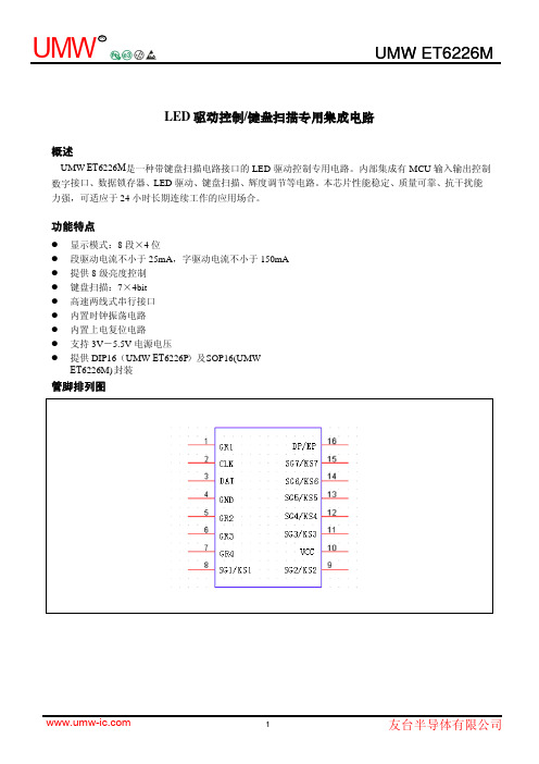
LED驱动控制/键盘扫描专用集成电路概述UMW E T6226M是一种带键盘扫描电路接口的LED驱动控制专用电路。
内部集成有MCU输入输出控制数字接口、数据锁存器、LED驱动、键盘扫描、辉度调节等电路。
本芯片性能稳定、质量可靠、抗干扰能力强,可适应于24小时长期连续工作的应用场合。
功能特点z显示模式:8段×4位z段驱动电流不小于25mA,字驱动电流不小于150mAz提供8级亮度控制z键盘扫描:7×4bitz高速两线式串行接口z内置时钟振荡电路z内置上电复位电路z支持3V-5.5V电源电压z提供DIP16(UMW ET6226P)及SOP16(UMWET6226M) 封装管脚排列图UMW6226管脚说明符 号管脚名称说 明SG1/KS1~ SG7/KS7 段驱动输出/键扫描输入LED 段驱动输出,高电平有效,也用作键扫描输入,高电平有效,内置下拉GR1~GR4 位/键扫描输出 LED 位驱动输出,低电平有效,也用作键盘扫描输出,高电平有效DP/KP 段/位输出LED 段输出,也用作键盘标志输出 CLK 时钟输入I2C 串行接口的数据时钟输入,内置上拉电阻 DAT 数据输入/输出I2C 串行接口的数据输入输出,内置上拉开漏模式VCC 电源端3-5.5V GND地端接地功能说明I 2C 总线接口通过DAT 和CLK 串行信号,可以使与MCU 之间进行信号传输。
因此,DAT 与CLK 构成了I 2C 总线接口。
数据信号当CLK 信号为高电平时,DAT 上的信号才会被认为是正确而稳定的信号。
而当CLK 信号在低电平时,DAT 上的信号才能做高低电平的转换。
如下图所示:开始和结束条件当CLK 信号为高电平,DAT 信号由高电平切换为低电平时表示串行信号传输“开始”。
当CLK 信号为高电平,DAT 信号由低电平切换为高电平时表示串行信号传输“结束”。
如下图所示:指令信号格式DAT线的指令信号格式有八位(bit),每一个指令信号后面需要有一个“确认”信号,并且以最大符号位“MSB”为首传送出去。
- 1、下载文档前请自行甄别文档内容的完整性,平台不提供额外的编辑、内容补充、找答案等附加服务。
- 2、"仅部分预览"的文档,不可在线预览部分如存在完整性等问题,可反馈申请退款(可完整预览的文档不适用该条件!)。
- 3、如文档侵犯您的权益,请联系客服反馈,我们会尽快为您处理(人工客服工作时间:9:00-18:30)。
UNISONIC TECHNOLOGIES CO., LTD
UM66TXXL CMOS IC
MELODY INTEGRATED CIRCUIT
DESCRIPTION
The UTC UM66TXXL series are CMOS LSI designed for using
in door bell, telephone and toy application. It is an on-chip ROM programmed for musical performance. Produced by CMOS technology, the device results in very low power consumption. Since the UTC UM66TXXL series include oscillation circuits a compact melody module can be constructed with only a few additional components.
FEATURES
*64-Note Rom memory
*1.5V ~ 4.5V power supply and low power consumption *Dynamic speaker can be driven with external NPN
transistor
*OSC resistor hold mode
*Power on reset: melody begins from the first note *Built in level hold mode
*Pb-free plating product number: UM66TxxLK
ORDERING INFORMATION
Order Number Pin Assignment
Normal Lead Free Plating Package 1 2 3
Packing
UM66TxxL-T92-B UM66TxxLK-T92-B TO-92 V SS V DD O/P Tape Box UM66TxxL-T92-K UM66TxxLK-T92-K TO-92 V SS V DD O/P Bulk UM66TxxL-T92-R UM66TxxLK-T92-R TO-92 V SS V DD O/P Tape Reel
SONG SERIES LIST
P/N SONG NAME
UTC UM66T05L Home Sweet Home UTC UM66T08L Happy Birthday UTC UM66T11L Love Me Tender UTC UM66T19L For Alice UTC UM66T32L COO COO waltz
ABSOLUTE MAXIMUM RATINGS (Operating temperature range applies unless otherwise specified.)
UNIT PARAMETER SYMBOL RATINGS
DC Supply Voltage V DD 1.5 ~ 4.5 V
Operating Temperature T OPR-10 ~ +60 °C
Storage Temperature T STG-55 ~ +125 °C
Notes: Stress above those listed under absolute maximum ratings may cause permanent damage to the device.
These are stress ratings only. Functional operations of this device at these or any other conditions above
those indicated in the operational section of this specification is not implied and exposure to absolute
maximum ratings conditions for extended periods may affect device reliably
ELECTRICAL CHARACTERISTICS (Vss=0V, Fosc=65536Hz, T J=25℃, unless otherwise specified)
FUNCTIONAL DESCRIPTION
OSCILLATOR CIRCUIT
The oscillator frequency is used as a time for tone and beat generators. Its accuracy affects the quality of the music.
TONE GENERATOR
Tone Frequencies are oscillator frequencies-M, where m is any even number from 64 to 256. Within a melody 14C scales can be selected including Pause code and End code. The tone generator is a programmed divider, The Range of Scales is from “C4” to “C6” and range of frequency varies from 258Hz to 23768Hz.
RHYTHM GENERATOR
The rhythm generator is also programmed dividers. It contain 15 available rhythms as
follows:1/4,1/2,3/4,1,1-1/4,1-1/2,1-/3/4,2,2-1/4,2-1/2,2-/3/4,3,3-1/4,3-1/2,3-/3/4.Four rhythms can be selected from these.
MELODY ROM
The Mask Rom can memorize 64 notes with 6 bit.4 bits are used for controlling the scale code and 2 bits are used for controlling the rhythm code.
TEMPO GENERATOR
There are 15 available tempos in the UTC UM66T series. The 15 tempos are:128,137,148,160,175,192,213, 240 , 274, 320,480,640,960,1920 J/minute.
APPLICATION CIRCUITS
Fig.1
Fig.2。
