AD408M86VQA-5中文资料
俄标闸阀

俄标闸阀另外,一般贸易出口额高于加工贸易出口额。
前5个月,机械工业一般贸易出口和加工贸易出口在机械工业出口贸易总额中的比重分别约为49%和46%,改变了长期以来机械工业出口加工贸易高于一般贸易的状况。
朱森第预测,下半年振兴装备制造业的政策将逐步发生积极影响,为机械产品提供可观的市场空间。
但是由于生产成本压力和部分原材料短缺的考验,将会挤占部分产品的利润空间。
发改委推动试点脱硫特许经营脱硫专业公司迎来新商机一、产品[平板闸阀]的详细资料:产品名称:平板闸阀二、执行标准:设计规范结构长度连接法兰试验与检验压力-温度产品标识JB/T5298 JB/T5298 JB/79 JB/T5298 GB9131 GB/T12220 API6D API6D ANSI-16.5 API6D ANSI B16.34 MSS SP-25 三、产口性能规范:设计等级常温下试验压力(MPa)适用温度℃适用介质壳体左密封左密封低压密封“G”型“D”型普通型“抗硫”型“基本”型公称压力PN (MPa )1.6 2.4 1.76 1.76 0.6-29~50-45~21-2~121H2S和CO2总含量大于500mg/m2的介质石油天然气、水等2.5 3.75 2.75 2.75 0.64.0 6.0 4.4 4.4 0.66.4 9.67.04 7.04 0.6磅级Lb 150 3.0 2.2 2.2 0.6 300 7.7 5.6 5.6 0.6四、主要零部件材料:阀门/阀盖WCB WC6 A352-LCB A351-CF8M 闸板2Cr13+ENP 20CrMoV+STL ANSO410+ENP ANSI316+ENP阀杆2Cr13 2Cr13 A182-A6a A182-A316S阀座25+PTFE 20CrMoV+STL A105+PTFE A182-F316+PTFE 填料NBR/FPM 柔性石墨/Flexible Graphite 聚四氟乙烯/PTFE+FPM 垫片-螺栓35 35CrMo A193-B7MA193-B8适用介质水、油口、蒸汽蒸汽、油品丙烷、乙烯硝酸类五、工洲牌平板闸阀主要外形和连接尺寸PN1.6MPa-2.5MPa:1.6MPa DN L D D1 D2 Do f b H H1 n-Φd凸面法法RF (K)Z43WF-16C (K)Z543WF-16C (K)Z643WF-16C (K)Z943WF-16C50 178 160 125 100 250 3 16 584 80 4-Φ18 65 190 180 145 120 250 3 18 634 95 4-Φ18 80 203 195 160 135 250 3 20 688 100 8-Φ18 100 229 215 181 155 300 3 20 863 114 8-Φ18 125 254 245 210 185 350 3 22 940 132 8-Φ18 150 267 280 240 210 350 3 24 1030 150 8-Φ23 200 292 335 295 265 350 3 26 1277 168 12-Φ23 250 330 405 355 320 400 3 30 1491 203 12-Φ25 300 356 460 410 375 450 4 30 1701 237 12-Φ25 350 381 520 470 435 500 4 34 1875 265 16-Φ30 400 406 580 525 485 305 4 36 2180 300 16-Φ30 450 432 640 585 545 305 4 40 2440 325 20-Φ34 500 457 705 650 608 305 4 44 2860 360 20-Φ41 600 508 840 770 718 305 5 48 3450 425 20-Φ41 700 610 910 840 788 305 5 50 3960 460 24-Φ41 800 660 1020 950 898 305 5 52 4550 512 24-Φ41 900 711 1120 1050 998 250 5 54 5250 565 28-Φ48 1000 811 1250 1170 1110 250 5 56 5870 630 28-Φ182.5MPa 50 178 160 125 100 250 3 20 584 80 4-Φ18凸面法法RF (K)Z43WF-25 (K)Z543WF-25 (K)Z643WF-265 190 180 145 120 300 3 22 634 95 8-Φ18 80 203 195 160 135 350 3 22 388 100 8-Φ18 100 229 230 190 160 350 3 24 863 114 8-Φ23 125 254 270 220 188 350 3 28 940 132 8-Φ25 150 267 300 250 218 400 3 30 1030 150 8-Φ25 200 292 360 310 278 450 3 34 1277 168 12-Φ255 (K)Z943WF-25 250 330 425 370 332 500 3 36 1491 203 12-Φ30 300 356 485 430 390 305 4 40 1701 237 16-Φ30 350 381 550 490 448 305 4 44 1875 265 16-Φ34 400 406 610 550 505 305 4 48 2180 300 16-Φ34 450 432 660 600 555 305 4 50 2440 325 20-Φ34 500 457 730 660 610 305 4 52 2860 360 20-Φ41 600 508 840 770 718 305 5 56 3450 425 20-Φ41 700 610 955 875 815 305 5 60 3960 460 24-Φ48 800 660 1070 990 930 305 5 64 4550 512 24-Φ48 900 711 1180 1090 1025 - 5 66 5250 595 28-Φ54 1000 811 1305 1210 1140 - 5 68 5870 660 28-Φ48六、无导流孔平板闸阀PN4.0MPa-10.0MPa:4.0MPaDN L D D1 D2 Y Do f f2 b H H1 n-Φd凹凸法法MFM (K)Z43 WF-40 (K)Z54 3WF-40 (K)Z64 3WF-40 (K)Z94 3WF-40 50 250 160 125 100 88 250 3 4 20 584 80 4-Φ18 65 280 180 145 120 110 250 3 4 22 634 95 8-Φ18 80 310 195 160 135 121 250 3 4 22 679 102 8-Φ18 100 350 230 190 160 150 300 3 4.5 24 863 115 8-Φ23 125 400 270 220 188 176 350 3 4.5 28 940 133 8-Φ25150 450 300 250 218 204 350 3 4.5 30104152 8-Φ25 200 550 375 320 282 260 350 3 4.5 381282188 12-Φ30 250 650 445 385 345 313 400 3 4.5 421495223 12-Φ34 300 750 415 450 408 364 450 4 4.5 461701250 16-Φ34 350 850 470 510 465 422 500 4 5 52188280 16-Φ34 400 950 655 585 535 474 305 4 5 58220310 20-Φ41 450 1050 680 610 560 524 305 4 5 60248335 20-Φ41 500 1150 755 670 612 576 305 4 5 62289380 20-Φ48 600 1350 890 795 730 678 305 5 6 62248450 20-Φ54 700 1450 995 900 835 768 305 5 6 683985500 24-Φ54 800 16501135103960 876 305 5 6 76475570 24-Φ586.4MPa50 250 175 135 105 88 250 3 4 26 584 90 4-Φ23凹凸法65 280 200 160 130 110 250 3 4 28 634 105 8-Φ23法MFM (K)Z43 WF-64 (K)Z54 3WF-64 (K)Z64 3WF-64 (K)Z94 3WF-64 80 310 210 170 140 121 250 3 4 30 679 110 8-Φ23 100 350 250 200 168 150 300 3 4.5 32 763 130 8-Φ25 125 400 295 202 176 350 3 4.5 36 970 150 8-Φ30-150 450 340 280 240 204 350 3 4.5 381038175 8-Φ34 200 500 405 345 300 260 350 3 4.5 441282210 12-Φ34 250 650 470 400 352 313 400 3 4.5 481495240 12-Φ41 300 750 530 460 412 364 450 4 4.5 541965270 16-Φ41 350 850 595 525 475 422 500 4 5 602185300 16-Φ41 400 950 670 585 525 474 305 4 5 662573335 16-Φ48 450 1050 715 630 570 524 305 4 5 68280360 20-Φ48 500 1150 800 705 640 576 305 4 5 70328405 20-Φ54600 1350 930 820 750 678 305 5 6 76 380 470 20-Φ5810.0MPa50 250 195 145 112 88 250 3 4 28 590 100 4-Φ25凹凸法法MFM (K)Z43 WF-100 (K)Z54 3WF-1 00 (K)Z64 3WF-1 00 (K)Z94 3WF-1 00 65 280 220 170 138 110 250 3 4 32 640 115 8-Φ25 80 310 230 180 148 121 250 3 4 34 680 120 8-Φ25 100 350 265 210 172 150 300 3 4.5 38 870 135 8-Φ30 125 400 310 250 210 176 350 3 4.5 42 980 155 8-Φ34150 450 350 290 250 204 350 3 4.5 46110180 12-Φ34 200 550 430 360 312 260 350 3 4.5 4541315220 12-Φ41 250 650 500 430 382 313 400 3 4.5 601605255 12-Φ41 300 75 585 500 442 364 450 4 4.5 701925295 16-Φ48 350 850 665 560 408 422 500 4 5 76228335 16-Φ54 400 950 715 620 558 474 305 4 5 80258360 16-Φ54七、有导流孔平板闸阀PN1.6MPa-10.0MPa:一、产品[不锈钢闸阀]的详细资料:产品名称:不锈钢闸阀产品特点:不锈钢闸阀价格,不锈钢闸阀厂家,不锈钢闸阀报价二、应用规范:公称压力:2.5MPa适用温度范围:-20~232℃~350℃适用介质:水、油、气及某些腐蚀性液体(W.O.G)螺纹类型:G?NPT.BSPT.BSP.DIN259/2999三、主要零件材料:序号NO. 零件名称材质1 阀体不锈钢CF8M/CF82 闸板不锈钢CF8M/CF83 阀杆不锈钢SS316/3044 阀盖不锈钢CF8M/CF85 填料聚四氟乙烯6 止推垫片不锈钢SS3047 阀杆架不锈钢SS316/SS3048 填料聚四氟乙烯PTFE9 螺母不锈钢SS30410 填料压盖螺母不锈钢SS316/SS30411 手轮铝合金12 铭牌铝13 手轮垫片不锈钢SS30414 手轮螺母不锈钢SS304四、不锈钢不锈钢闸阀主要连接尺寸及重量:SIZE 1/2″3/4″1″11/4″11/2″2″A 15 20 25 32 38 50H 90 97 108 120 146 163L 55 60 65 75 85 95D 70 70 80 80 90 100一、产品[弹性座封闸阀]的详细资料:产品名称:弹性座封闸阀产品特点:我厂引进欧州高科技阀门技术所生产的弹性座封闸阀,得用闸板整体包胶产生弹性变形的补偿作用达到良好的密封效果,克服了一般闸阀密封不良、漏水和生锈的现象,可广泛用于自来水、污水、建筑、石油、食品、医药、轻纺、电力、船舶、冶金、能源系统等流体管线上作为调节和截流装置使用。
AD集成库部分元件中英文对照
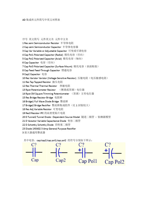
AD集成库元件简写中英文对照表序号英文简写元件英文名元件中文名1 Res semi Semiconductor Resistor 半导体电阻2 Cap semi Semiconductor Capacitor 半导体电容器3 Cap Var Variable or Adjustable Capacitor 可变或可调电容4 Cap Pol1 Polarized Capacitor (Radial) 极化电容(径向)5 Cap Pol2 Polarized Capacitor (Axial) 极化电容(轴向)6 Cap Capacitor 电容(径向)7 Cap Pol3 Polarized Capacitor (Surface Mount) 极化电容(表面贴装)8 Cap Feed Feed-Through Capacitor 馈通电容9 Cap2 Capacitor 电容10 ResVaristorVaristor (Voltage-Sensitive Resistor) 压敏电阻(电压敏感电阻)11 Res Tap Tapped Resistor 抽头电阻12 Res Thermal Thermal Resistor 热敏电阻13 Rpot Potentiometer Resistor (侧调或顶调)电位器14 Rpot SM Square Trimming Potentiometer (顶调)方形电位器15 Res Bridge Resistor Bridge 电阻桥16 Bridge1 Full Wave Diode Bridge 整流桥17 Bridge2 Bridge Rectifier 整流桥集成组件(比1封装较大)18 Res Adj Variable Resistor 可变电阻19 Res3 Resistor IPC的高密度贴片电阻20 D Tunnel2 Tunnel Diode - Dependent Source Model 隧道二极管- 依赖源模型21 D Varactor Variable Capacitance Diode 变容二极管22 DSchottkySchottky Diode 肖特基二极管23 Diode 1N5402 3 Amp General Purpose Rectifier3放大器通用整流器其中电容,cap/cap2/cap pol1/cap pol2 的符号分别如下所示:。
BAS86中文资料

BAS86中⽂资料DATA SHEETProduct speci?cationSupersedes data of 1996Mar 201996Oct 01DISCRETE SEMICONDUCTORSBAS86Schottky barrier diodelfpageM3D121Schottky barrier diode BAS86FEATURESLow forward voltageHigh breakdown voltage Guard ring protected Hermetically-sealed small SMD package. APPLICATIONSUltra high-speed switching Voltage clamping Protection circuits Blocking diodes.DESCRIPTION Planar Schottky barrier diode with anintegrated protection ring againststatic discharges.This surface mounted diode isencapsulated in a hermetically sealedSOD80C glass SMD package withtin-plated metal discs at each end. Itis suitable for “automatic placement”and as such it can withstandimmersion soldering.Fig.1 Simplified outline (SOD80C), pin configuration and symbol.handbook, halfpageMAM190k aCathode indicated by a grey band.LIMITING VALUESIn accordance with the Absolute Maximum Rating System (IEC 134).SYMBOL PARAMETER CONDITIONS MIN.MAX.UNIT V R continuous reverse voltage?50VI F continuous forward current?200mAI F(AV)average forward current see Fig.2?200mAI FRM repetitive peak forward current t p≤1sec.;δ≤0.5?500mAI FSM non-repetitive peak forward current t p=10ms5AT stg storage temperature?65+150°CT j junction temperature?125°CT amb operating ambient temperature?65+125°CSchottky barrier diodeBAS86ELECTRICAL CHARACTERISTICS T amb =25°C unless otherwise speci?ed.Note1.Pulsed test: t p =300µs;δ=0.02.THERMAL CHARACTERISTICS Note1.Refer to SOD80 standard mounting conditions.SYMBOL PARAMETERCONDITIONSMAX.UNIT V Fforward voltagesee Fig.3I F =0.1mA 300mV I F =1mA 380mV I F =10mA 450mV I F =30mA 600mV I F =100mA900mV I R reverse current V R =40V; see Fig.4; note 15µA t rr reverse recovery time when switched from I F =10mA to I R =10mA;R L =100?; measured at I R =1mA; see Fig.64ns C d diode capacitancef =1MHz; V R =1V; see Fig.58pFSYMBOL PARAMETERCONDITIONSVALUE UNIT R th j-a thermal resistance from junction to ambientnote 1320K/WSchottky barrier diodeBAS86GRAPHICAL DATAFig.2 Derating curve.handbook, halfpage 050100250050100150I F(AV)(mA)T ( C)amboMRA540Fig.3Forward current as a function of forward voltage; typical values. handbook, halfpage10I F V F (V)310(mA)21011011.20.80.40MSA892(3)(2)(1)(3)(2)(1)(1)T amb =125°C.(2)T amb =85°C.(3)T amb =25°C. (1)T amb =85°C.(2)T amb =25°C.(3)T amb =?40°C. handbook, halfpage 10510(nA)I R 4103102101011500MGC68610203040V R(3)Fig.4Reverse current as a function of reverse voltage; typical values.f =1MHz.Fig.5Diode capacitance as a function of reverse voltage; typical values.handbook, halfpage05012C d 048(pF)MGC68710203040V R (V)Schottky barrier diode BAS86Fig.6 Reverse recovery definitions.handbook, halfpage 90%10%t fQ dI dttIFI RMRC129 - 1F rSchottky barrier diodeBAS86PACKAGE OUTLINEDEFINITIONS LIFE SUPPORT APPLICATIONSThese products are not designed for use in life support appliances, devices, or systems where malfunction of these products can reasonably be expected to result in personal injury. Philips customers using or selling these products for use in such applications do so at their own risk and agree to fully indemnify Philips for any damages resulting from such improper use or sale.Data sheet status Objective speci?cation This data sheet contains target or goal speci?cations for product development.Preliminary speci?cation This data sheet contains preliminary data; supplementary data may be published later.Product speci?cation This data sheet contains ?nal product speci?cations.Limiting valuesLimiting values given are in accordance with the Absolute Maximum Rating System (IEC 134). Stress above one or more of the limiting values may cause permanent damage to the device. These are stress ratings only and operation of the device at these or at any other conditions above those given in the Characteristics sections of the speci?cation is not implied. Exposure to limiting values for extended periods may affect device reliability.Application informationWhere application information is given, it is advisory and does not form part of the speci?cation.Dimensions in mm. Cathode indicated by a grey band.Fig.7 SOD80C.handbook, full pagewidthMBA390 - 21.601.453.73.30.30.3O。
测速雷达主要设备功能及技术参数

测速雷达主要设备功能及技术参数测速雷达型号:KTR-C3(品牌:KITOZER/开拓者)采用高速DSP信号处理芯片、0.1秒快速捕捉。
1)设计小巧轻便、制作精良。
2)纯铸铁结构,坚固耐用。
3)232串口输出。
4)精确度高,捕捉目标速度快。
5)动态时具有同向功能。
6)静态时可分别检测来车、去车。
7)静态测速范围:0~322 KPH。
8)移动测速范围:19~322KPH。
9)环境要求:温度:-30度 ~ +70度;湿度:0 % ~ 90% 。
10)Ka波段窄波雷达,微波频率:34.7GHz(Ka-band),可有效规避探测狗检测。
11)发射角:±4度。
12)规格:重:0.52kg、直径:6.7cm、长:11.8cm。
13)精确度:+/-1KPH。
高清摄像机(品牌:KITOZER/开拓者)高清摄像机功能:CCD成像,200万象素,主要端口有:闪光灯同步口,通过同步线与闪光灯连接;拍照触发口,当收到外部脉冲触发信号时,高清摄像机会抓取一张图片,脉冲信号由独立的拍照触发器发出;网口(100M),与控制主机连接,接收参数配置,上传图片,也可接收带由协议内容的抓拍命令。
产品详细参数表百万像素变焦镜头日本精工本次中煤平朔公司系统百万像素变焦镜头选型为日本精工SE5018MP产品,AVENIR ETOKU(日本精工)十几年来始终专心于监控镜头的市场发展,成为中国安防监控领域用得最多的专业镜头。
本次系统高清摄像机选型为广州莱安智能化系统开发有限公司出品的KTR200A型高清摄像机。
KTR200A是集成一体的高速彩色/单色智能工业相机,采用总像素200万像素的CCD图像传感器,具有处理速度快、分辨率高、图像质量好等特点。
广泛应用于智能交通、电子警察、卡口、高速公路、停车厂等领域的检测和识别。
百万像素网络拍照摄像一体机,将高清图像抓拍、标清视频摄像完美结合,超高清晰度,分辨率达130万~500万像素,专业用于如平安城市建设、机场、银行、道路卡口监控及牌照识别等安全防范领域,能够为客户提供专业的可定制产品及服务,支持后续增值开发。
AD404M326VQA-5中文资料
ASCEND Semiconductor 4Mx4 EDO Data sheetDescriptionThe device CMOS Dynamic RAM organized as 4,194,304 words x 4 bits with extended data out access mode. It is fabricated with an advanced submicron CMOS technology and designed to operate from a single 3.3V oniy power supply. Low voltage operation is more suitable to be used on battery backup, portable elec-tronic application. lt is packaged in JEDEC standard 26/24-pin plastic SOJ or TSOP(II).Features• Single 3.3V(%) only power supply • High speed t RAC acess time: 50/60ns • Low power dissipation- Active mode : 432/396 mW (Mas) - Standby mode: 0.54 mW (Mas)• Extended - data - out(EDO) page mode access • I/O level: CMOS level (Vcc = 3.3V)• 2048 refresh cycle in 32 ms(Std.) or 128 ms(S-version)• 4 refresh modesh: - RAS only refresh- CAS - before - RAS refresh - Hidden refresh - Self-refresh(S-version)10±Pin Name FunctionA0-A10Address inputs- Row address - Column address - Refresh address DQ1~DQ4Data-in / data-out RAS Row address strobe CAS Column address strobe WE Write enable OE Output enable Vcc Power (+ 3.3V)VssGroundVCC 1DQ12DQ23DQ34DQ45VCC6891011 NC 12 WE 13A0 A117 A218 A319VSS RAS CAS OE A8A7A6A5A4VSSAD404M42VSPin Description Pin Configuration21222324 2526151416 A1026/24-PIN 300mil Plastic SOJA9VCC 1DQ12DQ23DQ34DQ45VCC6891011 NC 12 WE 13A0 A117 A218 A319VSS RAS CAS OE A8A7 A6A5 A4VSSAD404M42VT212223242526151416 A1026/24-PIN 300mil Plastic TSOP (ll)A9A0-A10A0-A10A0-A10WECASNO. 2 CLOCK GENERATORCOLUMN ADDRESS BUFFERS (11)REFRESH CONTROLLERREFRESH COUNTERBUFFERS (11)ADDRESS ROW NO. 1 CLOCK GENERATORA0RASA1A2A3A4A5A6A7A8CONTROLLOGICDATA-IN BUFFERDATA-OUT BUFFEROEDQ1.DQ4.COLUMN DECODER2048SENSE AMPLIFIERSI/O GATING2048x42048x2048x4MEMORY ARRAY2048R O W D E C O D E RVcc VssBlock DiagramA9A10TRUTH TABLENotes: 1. EARLY WRITE only.FUNCTIONRASCAS WE OE ADDRESSESDQ SNotesROW COL STANDBY H X X X X High-Z READL L H L ROW COL Data-Out WRITE: (EARLY WRITE )L L L X ROW COL Data-lnREAD WRITE L L ROW COL Data-Out,Data-ln EDO-PAGE-MODE READ1st Cycle L H L ROW COL Data-Out 2nd CycleL H L n/a COL Data-Out EDO-PAGE MODE WRITE1st CycleL L X ROW COL Data-In 2nd Cycle L L Xn/a COL Data-InEDO-PAGE-MODEREAD-WRITE 1st Cycle L ROW COL Data-Out, Data-In 2nd Cycle L n/a COL Data-Out, Data-In HIDDEN REFRESHREAD L H L ROW COL Data-Out WRITEL L X ROW COL Data-In 1RAS-ONLY REFRESH L H X X ROW n/a High-Z CBR REFRESHLHXXXHigh-ZH X →H L →L H →H L →H L →H L →H L →H L →H L →L H →H L →H L →L H→L H L →→L H L→→H L→Absolute Maximum RatingsRecommended DC Operating ConditionsCapacitanceTa = 25°C, V CC = 3.3V%, f = 1MHz Note: 1. Capacitance measured with effective capacitance measuring method. 2. RAS, CAS = V IH to disable Dout.ParameterSymbol Value Unit Voltage on any pin relative to Vss V T -0.5 to + 4.6V Supply voltage relative to Vss V CC -0.5 to + 4.6V Short circuit output current I OUT 50mA Power dissipation P D 1.0WOperating temperature T OPT 0 to + 70°C Storage temperatureT STG-55 to + 125°CParameter/Condition Symbol3.3 Volt VersionUnitMinTyp MaxSupply VoltageV CC 3.0 3.33.6V Input High Voltage, all inputs V IH 2.0-V CC + 0.3V Input Low Voltage, all inputsV IL-0.3-0.8VParameterSymbol Typ Max Unit Note Input capacitance (Address)C I1 -5pF 1Input capacitance (RAS, CAS, OE, WE)C I2-7pF 1Output capacitance(Data-in, Data-out)C I/O-7pF1, 210±DC Characteristics :(T a = 0 to 70°C, V CC = + 3.3V%, V SS = 0V)Parameter Symbol Test Conditions AD404M42V Unit Notes-5-6Min Max Min MaxOperating current I CC1RAS cyclingCAS, cyclingt RC = min-120-110mA1, 2Standby Current LowpowerS-versionI CC2LVTTL interfaceRAS, CAS = V IHDout = High-Z-0.5-0.5mACMOS interfaceRAS, -0.2VDout = High-Z-0.15-0.15mAStandardpowerversionLVTTL interfaceRAS, CAS = V IHDout = High-Z-2-2mACMOS interfaceRAS,-0.2VDout = High-Z-0.5-0.5mARAS- only refresh current I CC3RAS cycling, CAS = V IHt RC = min-120-110mA1, 2 EDO page mode current I CC4t PC = min-90-80mA1, 3CAS- before- RAS refresh current I CC5t RC = minRAS, CAS cycling-120-110mA1, 2Self- refresh current (S-Version)I CC8 - 550 - 55010±CAS V CC≥CAS V CC≥t RASS100µs≥µADC Characteristics :(T a = 0 to 70°C , V CC = +3.3V %, V SS = 0V)Notes:1. I CC is specified as an average current. It depends on output loading condition and cycle rate when the device is selected. I CC max is specified at the output open condition.2. Address can be changed once or less while RAS = V IL .3. For I CC4, address can be changed once or less within one EDO page mode cycle time.Parameter Symbol Test Conditions AD404M42VUnitNotes-5-6Min MaxMin MaxInput leakage current I LI + 0.3V -55-55Output leakage current I LO + 0.3V Dout = Disable -55-55Output high Voltage V OH I OH = -2mA 2.4- 2.4-V Output low voltage V OLI OL = +2mA-0.4-0.4V10±0V Vin V CC ≤≤µA 0V Vout V CC ≤≤µAAC Characteristics(T a = 0 to + 70°C , V cc = 3.3V %, V ss = 0V) *1, *2, *3, *4Test conditions• Output load: one TTL Load and 100pF (V CC = 3.3V %)• Input timing reference levels:V IH = 2.0V, V IL = 0.8V (V CC = 3.3V %)• Output timing reference levels:V OH = 2.0V, V OL = 0.8V10±10±10±Read, Write, Read- Modify- Write and Refresh Cycles (Common Parameters)ParameterSymbol AD404M42V UnitNotes-5-6Min MaxMin MaxRandom read or write cycle time t RC 84-104-ns RAS precharge timet RP 30-40-ns CAS precharge time in normal mode t CPN 10-10-ns RAS pulse width t RAS 50100006010000ns 5CAS pulse width t CAS 8100001010000ns 6Row address setup time t ASR 0-0-ns Row address hold time t RAH 8-10-ns Column address setup time t ASC 0-0-ns 7Column address hold time t CAH 8-10-ns RAS to CAS delay timet RCD 12371445ns 8RAS to column address delay time t RAD 10251230ns 9Column address to RAS lead time t RAL 25-30-ns RAS hold time t RSH 8-10-ns CAS hold timet CSH 38-40-ns CAS to RAS precharge time t CRP 5-5-ns 10OE to Din delay time t OED 12-15-ns Transition time (rise and fall)t T 150150ns 11Refresh periodt REF -32-32ms Refresh period (S- Version)t REF -128-128ms CAS to output in Low- Z t CLZ 0-0-ns CAS delay time from Din t DZC 0-0-ns OE delay time from Dint DZO-0-nsRead CycleWrite Cycle Parameter SymbolAD404M42V Unit Notes-5-6Min Max Min MaxAccess time from RAS t RAC-50-60ns12 Access time from CAS t CAC-14-15ns13, 14 Access time from column address t AA-25-30ns14, 15 Access time from OE t OEA-12-15nsRead command setup time t RCS0-0-ns7 Read command hold time to CAS t RCH0-0-ns10, 16 Read command hold time to RAS t RRH0-0-ns16 Output buffer turn-off time t OFF012015ns17 Output buffer turn-off time from OE t OEZ012015ns17Parameter SymbolAD404M42V Unit Notes -5-6Min Max Min MaxWrite command setup time t WCS0-0-ns7, 18 Write command hold time t WCH8-10-nsWrite command pulse width t WP8-10-nsWrite command to RAS lead time t RWL13-15-nsWrite command to CAS lead time t CWL8-10-nsData-in setup time t DS0-0-ns19 Data-in hold time t DH8-10-ns19 WE to Data-in delay t WED10-10-nsRead- Modify- Write CycleRefresh Cycle Parameter SymbolAD404M42V Unit Notes-5-6Min Max Min MaxRead-modify- write cycle time t RWC108-133-nsRAS to WE delay time t RWD64-77-ns18 CAS to WE dealy time t CWD26-32-ns18 Column address to WE delay time t AWD39-47-ns18 OE hold time from WE t OEH8-10-nsParameter SymbolAD404M42VUnit Notes -5-6Min Max Min MaxCAS setup time (CBR refresh) t CSR5-5-nsCAS hold time (CBR refresh)t CHR8-10-ns10 RAS precharge to CAS hold time t RPC5-5-ns7 RAS pulse width (self refresh)t RASS100-100-RAS precharge time (self refresh)t RPS90-110-nsCAS hold time (CBR self refresh)t CHS-50--50-nsWE setup time t WSR0-0-nsWE hold time t WHR10-10-nsµsEDO Page Mode CycleEDO Page Mode Read Modify Write CycleParameterSymbol AD404M42VUnit Notes-5-6Min MaxMin MaxEDO page mode cycle timet PC 20-25-ns EDO page mode CAS precharge time t CP 10-10-ns EDO page mode RAS pulse width t RASP 5010560105ns 20Access time from CAS precharge t CPA -30-35ns 10, 14RAS hold time from CAS precharge t CPRH 30-35-ns OE high hold time from CAS high t OEHC 5-5-ns OE high pulse widtht OEP 10-10-ns Data output hold time after CAS low t COH 5-5-ns Output disable delay from WEt WHZ 310310ns WE pulse width for output disable whenCAS hight WPZ7-7-nsParameterSymbol AD404M42V Unit Notes -5-6Min MaxMin MaxEDO page mode read- modify- write cycle CAS precharge to WE delay timet CPW 45-55-ns 10EDO page mode read- modify- write cycle timet PRWC56-68-nsNotes :1. AC measurements assume t T = 2ns.2. An initial pause of 100 is required after power up, and it followed by a minimum of eightinitialization cycles (RAS - only refresh cycle or CAS - before - RAS refresh cycle). If the internal refresh counter is used, a minimun of eight CAS - before - RAS refresh cycles are required.3. In delayed write or read-modify-write cycles, OE must disable output buffer prior to applying data to the device.4. All the V CC and V SS pins shall be supplied with the same voltages.5. t RAS (min) = t RWD (min)+t RWL (min)+t T in read-modify-write cycle.6. t CAS (min) = t CWD (min)+t CWL (min)+t T in read-modify-write cycle.7. t ASC (min), t RCS (min), t WCS (min), and t RPC are determined by the falling edge of CAS .8. t RCD (max) is specified as a reference point only, and t RAC (max) can be met with the t RCD (max) limit.Otherwise, t RAC is controlled exclusively by t CAC if t RCD is greater than the specified t RCD (max) limit. 9. t RAD (max) is specified as a reference point only, and t RAC (max) can be met with the t RAD (max) limit.Otherwise, t RAC is controlled exclusively by t AA if t RAD is greater than the specified t RAD (max) limit. 10. t CRP , t CHR , t RCH , t CPA and t CPW are determined by the rising edge of CAS .11. V IH (min) and V IL (max) are reference levels for measuring timing or input signals. Therefore, transitiontime is measured between V IH and V IL .12. Assumes that t RCD tRCD (max) and t RAD t RAD (max). If t RCD or t RAD is greater than the maximum recommended value shown in this table, t RAC exceeds the value shown. 13. Assumes that (max) and (max).14. Access time is determined by the maximum of t AA , t CAC , t CPA . 15. Assumes that (max) and (max). 16. Either t RCH or t RRH must be satisfied for a read cycle.17. t OFF (max) and t OEZ (max) define the time at which the output achieves the open circuit condition (highimpedance). t OFF is determined by the later rising edge of RAS or CAS.18. t WCS , t RWD , t CWD , and t AWD are not restrictive operating parameters. They are included in the datasheet as electrical characteristics only. If (min), the cycle is an early write cycle and the data out will remain open circuit (high impedance) throughout the entire cycle. If (min),(min), (min) and (min), the cycle is a read-modify-write and the data output will contain data read from the selected cell. If neither of the above sets of conditions is satisfied, the condition of the data output (at access time) is indeterminate.19. These parameters are referenced to CAS separately in an early write cycle and to WE edge in adelayed write or a read-modify-write cycle.20. t RASP defines RAS pulse width in EDO page mode cycles.µs ≤≤t RCD t RCD ≥t RADt RAD ≤t RCD t RCD ≤t RAD t RAD ≥t WCS t WCS ≥t RWD t RWD ≥t CWDt CWD ≥t AWD t AWD ≥t CPW t CPW≥Timing Waveforms• Read Cyclet RC t RASt RPtCRPtCPNtRRHtRCHt OEZ t OFF tOEA tCACt AAtRACt CLZD OUTtRCS t ASR tRAH tASC tCAH tRAD t RALtCAStRSH tRCDt TtCSHRASCASADDRESSWEDQ1~DQ4Note : = don’t care OEt OFFRowColumn= Invalid Dout•Early Write CycletRC t RASt RPt WCHt DSt DHt WCS t RALtCAStRSH tRCDt TtCSHRASCASWEDQ1~DQ4tCRPtASRtRAH tASCtCAH ADDRESSColumnRowtCPND INtRADt RAL• Delayed Write CycletRC t RASt RPt RWL t RCSt CAStRSH tRCDt TtCSHRASCAStASR tRAH tCAHADDRESSColumnRow tASC D INDQ1~DQ4WEtCRPtCPNt DHt DSt OEHt OEDOEt DSOPENt WPt CWL• Read - Modify - Write CycletRWC t RASt RPtRWDt WPtRADtRWL tCAStCWL tRCDt TtCPNRASCASWEtCRP t ASRtRAHtASCtCAHADDRESS Column RowDQ1~DQ4t DHt DSOEtRCStAWD tCWD D INt OEDt OEHt OEZt OEA t CAC t RACt AADQ1~DQ4D OUTOPENtDZCtDZO• EDO Page Mode Read CycletRASPtCPRHt RCStCAStRSH tRCDt OEAtCSHRASCAStASRtRAHtCAHADDRESStCASWEtCRPt CPOEDQ1~DQ4OPENtOEPD OUT 1t PCt CPtCAStCPNtCRPtRADtCAHtASCt ASCtCAHt ASCt RAL Row Column 1t OEAt OEHCtRRH tRCHt RACt AAt AAt AA t CPA t CPA t OEZt OFFt OFFt CACt OEZt CAC t CACt COHD OUT NWE OE Column 2Column N Rowt RPD OUT 2• EDO Page Mode Early Write CycletRASPtRPt WCSt CAStRSH tRCDRASCAStASRtRAHtCAHADDRESStCASWEt CPDQ1~DQ4t PCt CPt CAStCPNtCRP tCAH tASCtASC tCAH tASC Row Column 1t DS WE Column 2Column Nt WCH t WCS t WCH t WCS t WCHt DH t DS t DH t DS t DHD IN 1D IN 2D IN Nt TtCSH• EDO Page Mode Read-Early-Write Cyclet RASPtCPRHt RCStCAStRSH tRCDt OEAtCSHRASCAStASRtRAHtCAHADDRESStCASWEtCRPt CPOEDQ1~DQ4OPENtWEDt PCt CPtCAStCPNtCRPtRADtRAHtASCt ASCtCAHt ASCt RAL Row Column 1tWCStRCHt RACt AAt AAt CPA t DHt WHZt CACt CACt COHWE OE Column 2Column N Rowt RPt CAL tWCHDataDoutput 2Data Input NDataDoutput 1t DStCSH• EDO Page Mode Read-Modify-Write Cyclet RASPt CPRHt RCStCASt WP RASCASt ASRtRAHtCAHADDRESSt CASWEtRCDCPDQ1~DQ4tPRWCt CPtCAStCRPtRADtCAHtASCt ASCtCAH tASC Row Column 1tRWLtRCSt OEDt DZOt CAC WE OEt RPt RAL D OUT 2D OUT ND OUT 1tTt Column NColumn 2Column 1tRWD tAWD tCWDtCWLtRCStCWDtAWD tCPW tCWL tCPW tAWD tCWDtCWL t OEDt OEDt OEHt OEHt OEHt CAC t CAC t OEA t AAt RACt OEZt OEAt AA t CPAt OEZt OEAt AA t CPAt OEZ t DSt DHt WP t DSt DHt WP t DSt DHOPENOPENOPEN D IN 1D IN ND IN 2DQ1~DQ4t DZCt DZOt DZCt DZCt DZO• Read Cycle with WE Controlled Disablet WPZt RCStCAStRCDt TtCSHRASCASt ASRtRAHtCAHADDRESSColumnRow tASCD DQ1~DQ4WEt OEZt DSt WHZOEt RCH t OEA t CACt AAt RACt CLZOUTtRADRASADDRESSt RC t CRPt ASRt RAHt Tt RPCROWt OFFCAS t RASt RPOPENt CRPDQ1~DQ4RASt CSRt WSRt RPt T t RPCt OFFCAS t RASt RPOPENt CRPDQ1~DQ4t RPCt CHRt RASt RPt RCt RCt CHRt CSRt WHRt WSRt WHRWECAS-Before-RAS Refresh CycleRASWEt RPCt OFFt CSRt CHSt WSRCASt RASS t RPSOPENDQ1~DQ4t WHRHigh lmpedance• Hidden Refresh Cyclet RPt RASRASt RCDt CRPADDRESSWEt CHRt CASt RSHt RAHt ASRt ASCt CAHt RAL ROW t RCHt OEZCASDQ1~DQ4t Tt RCSD t RASt RASt RPt RPt RC t RCt RCt RADt RRHt OFF t OFFt OEA t CACt AAt RACCOlumnOUTOE(READ)(REFRESH)(REFRESH)Ordering informationAD404M42VSA-5• AD• Ascend Memory Product • 40 • Device Type• 4M4 • Density and Organization • 2• Refresh Rate, 2: 2K Refresh • V• T: 5V, V: 3.3V• S • Package Type (S : SOJ, T : TSOP II)• A• Version• 5• Speed (5: 50 ns, 6: 60 ns)Part Number Access time PackageAD404M42VSA-5AD404M42VSA-6AD404M42VTA-5AD404M42VTA-650 ns 60 ns 50 ns 60 ns300mil 26/24-Pin Plastic SOJTSOP IIPackaging information • 300 mil, 26/24-Pin Plastic SOJ• 300 mil, 26/24-Pin TSOP II。
资料芯片

TDA4605脚号引脚代码引脚功能参数:R+lR- 备注1,该集成块为双列8 脚封装2.电源:6脚为+12.00V3.主要用途:开关电源控制/Jw动电路4.此数据在长虹2138FD型彩电上测得,仅供参考5.内部框图见图387I NF 反馈电压输入0.59/0.592 I 初级电流取样13.00/6.32 '3 V IN 初级电流监测输入6.71/6.024 GND 地0/05 OUT 脉冲输出1 .12/1.126 Vcc 电源(范围为7.25-16V) 16.02/5.337 SOFT 软启动和积分电路音频输入11.48/7.208 FT 振荡器反馈输入7.83/6.50TDA4605开关电源集成电路TDA4605是飞利浦公司在TDA4601基础上改进开发的一种驱动场效应管的开关稳压控制集成电路。
1.内电路方框图TDA4605集成电路内含启动脉冲发生器、参考电压发生器、误差放大器、恒流源与电流控制输出器,以及各种电压检测器,过流、过压、欠压等保护电路。
该电路采用逻辑运算控制器,根据采样输入电压高低与负载轻重自动调整输出脉冲的占空比。
具有突发脉冲工作方式,还具有控制环开路或短路的保护功能和市电过低就关闭电源的特性,其内电路方框图如图所示。
2.引脚功能及数据TDA4605集成电路通常与场效应开关管配套构成工作频率为500 kHz的开关电源,故开关电源的效率较高。
TDA4605(k Q集成电路采用8脚封装,其集成电路的引脚功能及数据见表所列。
TDA4605-3集成电路内含稳压取样电压处理电路,欠压保护检测电路、激励脉冲输出电路、软启动控制电路等。
该IC采用8脚封装方式,其集成电路的引脚功能及数据见表所列。
TB1240N2.21 1.该集成块为双列33脚封装2.电源:3脚、17 脚、28脚、32脚为+9.10V, 6脚、16 脚为+5.00V3.振荡/时钟:11 脚、10脚、11脚4.主要用途:中频/彩色/扫描信号处理电路5.内部框图见图3671 AFT OUT 频率控制输出2 AUDIO DEEM 音频信号输出4.203 IF Vcc 电源9.104 SIF IN 伴音中频输入5.005 IF GND 地06 IF IN 图像中频输入1.987 IF IN 图像中频输入1.988 RF AGC OUT 射频AGC电压输出4.389 IF AGC FILTER 中频AGC信号滤波4.2010 APC FILTER 自动色相位控制信号滤波2.3811 XTAL 副载波外接晶体振荡器(4.43MHz)12 Y/C GND 地013 MODE SW 模式开关014 R IN 红基色字符输入2.6115 G IN 绿基色字符输入2.6116 B IN 蓝基色字符输入2.6117 红绿蓝Vcc 电源9.1018 R OUT 红基色输出2.8019 G OUT 绿基色输出2.8020 B OUT 蓝基色输出2.8021 ABL 自动亮度控制6.02、22 V SAW 场锯齿波形成4.1023 V NIB 场锯齿波反馈信号输入4.9124 V DRIVER OUT 场激励信号输出1.3025 V AGC 场自动增益控制信号滤波1.8026 SCL 12C总线串行时钟线4.10-27 SDA 12C总线串行数据线J 4.2028 H Vcc 电源8.7829 ID/CW OUT 识别了色副载波输出3.7130 H BLANK IN 行扫描字符消隐输入1.4231 SYNC OUT 同步脉冲信号输出4.6832 H DRIVER OUT 行激励输出1.8033 GND 地0TDA9332H 脚号引脚代码引脚功能参数:静动v 备注1.该集成块为四一列扁平44脚封装2.电源:39脚为+8.00V3.振荡/时钟:10 一脚、20脚、21脚4.主要用途:视一频信号三基色处理_电路5.此数据在长虹DT2000彩电上测一得,仅供参考6.内部框图见图一427 户1 V- 场驱动反相输出2.25/2.302 V十场驱动同相输出2.26/2.313 E/W OUT E/W校正脉冲输出3.36/3.264 EHT EHT高压检测信号输入1.54/1.455 NC 未用0.07/0.066 GND 地0/07 DIGSUP 数据电路退藕5.00/5.008 H OUT 行激励脉冲输出0.67/6.679 SAND OUT 沙堡脉冲输出0.78/0.7810 SCL 时钟线3.04/3.10(不定值)11 SDA 数据线2.90/3.00(不定值)12 H SEL 未用4.16/4.9513 H FBP IN 行逆程脉冲输入0.60/0.5714 DPC 动态相位校正脉冲输入3.56/3.2015 V SAW 场锯齿波形成电容0/0.0316 Im 场锯齿波发生器基准电流3.89/3.8917 Vcc 行启动电源输入8.08/8.0518 BANDGAP 稳压电源信号滤波电容4.75/4.7519 GND 地0/020 XTAL 外接晶体振荡器1.22/1.0521 XTAL 外接晶体振荡器1.05/1.0722 L PST-UP 未用0.04/0.0423 V SYNC IN 场扫描同步脉冲信号输入0.02/0.0424 H SYNC IN 行扫描同步脉冲信号输入0.99/0.4025 DAC OUT 未用0.87/0.33、26 R-Y IN 红基色色差输入3.58/3.6027 B-Y IN 蓝基色色差输入3.60/3.5128 YIN 亮度信号输入3.40/3.4629 FBCSO 地0.05/0.0430 RIN1 红基色输入2.58/2.5831 GINl 绿基色输入2.58/2.5832 BIN1 蓝基色输入2.58/2.5833 Ys IN 快速消隐脉冲信号输入1.98/0.0434 PWL 白峰值限制退祸0.18/0.1435 RIN2 红基色输入3.55/3.5436 GIN2 绿基色输入3.54/3.5437 BIN2 蓝基色输入3.54/3.5438 Ys IN 快速消隐脉冲/混合信号输入/00 同上39 Vcc 电源8.00/8.0040 R OUT 红基色输出2.50/2.5041 G OUT 绿基色输出2.48/2.5342 B OUT 蓝基色输出2.51/2.5643 ABL 自动束流限制2.47/2.4644 BLACK 黑电流信号输入6.95/6.95TDA9332H It总线撞制的TV显示处理集成电路TDA9332H是飞利浦公司为高档彩电设计的显示处理集成电路,应用于各种新型大屏幕彩色电视机1.功能特点(1)具有nJV输入端和带快速消隐的RGB信号输入端,不仅将OSDII'ext输入端与其他视频信号输入端分开,而且既有快速消隐功能又可混合插入;同时内设RGB控制处理器,能实施连续阴极校正(CCC),白点和黑电平偏移调整;可提供黑电流稳定的BGR 输出。
平衡机865adpt中文说明书

269
8.3 不平衡测量
269
259 8.4 固定平衡重块
270
259
8.4.1 不平衡重量分解(分离)
270
259
8.4.2 不带 Easyfix®
270
259
8.4.3 带 Easyfix®
270
8.5 手动游标卡尺
271
259
8.5.1 确定轮辋宽度
271
259
8.5.2 安放平衡重块
271
4. 首次开机调试
4.1 打开包装
1. 去除带钢和支撑夹。 2. 小心地向上去除包装。 3. 配件和包装材料。
3. MT865ADPT 用起重机提升。 在预先设定的区域进行安装, 请注意中说明的最小间距。
ii检测 MT865ADPT 和配件是否状态良好以及有无受到损坏的
部件。如果出现可疑情况,不要开机调试,并与客户服务
266 13. 技术参数 27
279
266 13.1 MT865ADPT
279
266 13.2 尺寸和重量
279
266 13.3 工作范围
279
267
1. 应用的标志
1.1 文件资料
警告说明是由危险、警告和小心的信号标语和象形图组成, 并始终提示使用者直接导致或可能出现的危险。
危险! 直接会导致人员遭受重伤或死亡的危险。
277
11.4.5 检查测量
278
265 11.5 自身诊断
278
265
265 12. 停机 27
279
265 12.1 暂时停机
279
12.2 更换地点
279
266 12.3 清除垃圾及废物销毁
AD8005中文资料

TMIN to TMAX Offset Drift +Input Bias Current TMIN to TMAX –Input Bias Current Input Bias Current Drift (± ) Open-Loop Transimpedance INPUT CHARACTERISTICS Input Resistance Input Capacitance Input Common-Mode Voltage Range Common-Mode Rejection Ratio OUTPUT CHARACTERISTICS Output Voltage Swing Output Current Short Circuit Current POWER SUPPLY Quiescent Current Power Supply Rejection Ratio OPERATING TEMPERATURE RANGE
元器件交易网
a
FEATURES Ultralow Power 400 A Power Supply Current (4 mW on ؎5 VS) Specified for Single Supply Operation High Speed 270 MHz, –3 dB Bandwidth (G = +1) 170 MHz, –3 dB Bandwidth (G = +2) 280 V/ s Slew Rate (G = +2) 28 ns Settling Time to 0.1%, 2 V Step (G = +2) Low Distortion/Noise –63 dBc @ 1 MHz, V O = 2 V p-p –50 dBc @ 10 MHz, VO = 2 V p-p 4.0 nV/√Hz Input Voltage Noise @ 10 MHz Good Video Specifications (RL = 1 k⍀, G = +2) Gain Flatness 0.1 dB to 30 MHz 0.11% Differential Gain Error 0.4؇ Differential Phase Error APPLICATIONS Signal Conditioning A/D Buffer Power-Sensitive, High-Speed Systems Battery Powered Equipment Loop/Remote Power Systems Communication or Video Test Systems Portable Medical Instruments PRODUCT DESCRIPTION
AD009-03(GPM6P1009A)产品规格书
16-pin Remote Controller with 8KB OTP ROM
Preliminary
OCT. 29, 2010 Version 0.1
GENERALPLUS TECHNOLOGY INC. reserves the right to change this documentation without prior notice. Information provided by GENERALPLUS No
TECHNOLOGY INC. is believed to be accurate and reliable. However, GENERALPLUS TECHNOLOGY INC. makes no warranty for any errors which may appear in this document. Contact GENERALPLUS TECHNOLOGY INC. to obtain the latest version of device specifications before placing your order. responsibility is assumed by GENERALPLUS TECHNOLOGY INC. for any infringement of patent or other rights of third parties which may result from its use. In addition, GENERALPLUS products are not authorized for use as critical components in life support devices/systems or aviation devices/systems, where a malfunction or failure of the product may reasonably be expected to result in significant injury to the user, without the express written approval of Generalplus.
Analog Devices ADTL082A ADTL082J ADTL084J 双通道操作电路模

Rev. BInformation furnished by Analog Devices is believed to be accurate and reliable. However, noresponsibility is assumed by Analog Devices for its use, nor for any infringements of patents or other rights of third parties that may result from its use. Speci cations subject to change without notice. No license is granted by implication or otherwise under any patent or patent rights of Analog Devices. T rademarks and registered trademarks are the property of their respective owners.One Technology Way, P.O. Box 9106, Norwood, MA 02062-9106, U.S.A. Tel: 781.329.4700 Fax: 781.461.3113 ©2007 Analog Devices, Inc. All rights reserved.引脚配置OUT A1–IN A2+IN A3–V4+V8OUT B7–IN B6+IN B5ADTL082JTOP VIEW(Not to Scale)6275-1OUT A1–IN A2+IN A3–V4+V8OUT B7–IN B6+IN B5ADTL082ATOP VIEW(Not to Scale)6275-2OUT A1–IN A2+IN A3+V4OUT D14–IN D13+IN D12–V11+IN B5+IN C10–IN B6–IN C9OUT B7OUT C8ADTL084JTOP VIEW(Not to Scale)6275-3ADTL084A1234567–IN A+IN A+VOUT B–IN B+IN BOUT A141312111098–IN D+IN D–VOUT C–IN C+IN COUT DTOP VIEW(Not to Scale)6275-4低成本、JFET输入运算放大器ADTL082/ADTL084产品特性TL082/TL084兼容低输入偏置电流:10 pA(最大值)失调电压5.5 mV(最大值,ADTL082A/ADTL084A)9 mV(最大值,ADTL082J/ADTL084J)工作电压:±15 V低噪声:16 nV/√Hz宽带宽:5 MHz压摆率:20 V/μs共模抑制比(CMRR):80 dB(最小值)总谐波失真: 0.001%电源电流:1.2 mA(典型值)单位增益稳定应用通用放大功率控制和监测有源滤波器工业/过程控制数据采集采样保持电路积分器输入缓冲图1. 8引脚SOIC_N(R-8)图2. 8引脚MSOP(RM-8)图3. 14引脚SOIC_N(R-14)图4. 14引脚TSSOP(RU-14)概述ADTL082和ADTL084均为具有业界领先性能的JFET输入放大器,其性能优于TL08x器件。
ZMM5V6中文资料

30
40
20
20
10
0
0
VZ, ZENER VOLTAGE (V) Fig. 1, Zener Current vs Zener Voltage
15
600
NOT FOR NEW DESIGN, 1000 USE BZT52C2V4 - BZT52C51
DIFFERENTIAL ZENER IMPEDANCE (W)
VR = 2V Tj = 25°C
5
25
200
Cj, JUNCTION CAPACITANCE (pF)
150
100
50
0
0
5
10
15
20
25
VZ, ZENER VOLTAGE (V) Fig. 5, Junction Capacitance vs Zener Voltage
DS18005 Rev. H-3
Characteristic Forward Voltage @ IF = 200mA Thermal Resistance, Junction to Ambient Air (Note 2) Operating and Storage Temperature Range Notes:
1. Tested with Pulses, tp = 20ms. 2. Valid provided that Electrodes are kept at Ambient Temperature.
DS18005 Rev. H-3
2 of 3
ZMM2V4-ZMM75
元器件交易网
100
50
Ptot = 500mW TA = 25°C
IOS-MAT-0054_CNv5
参考
本技术规范中化学品要求和测试所引用的标准,如欧盟指令,都适用标准、指令的最新版本,除非 另有说明。
本资料仅供参考,英文版本 IOS-MAT-0054 具有最终法律效力。
1 of 23 2009-10-26 Elsa Hou 译稿
表2. 实木、木基材料和天然材料的要求
物质
要求
测试方法
文件
硼及其化合物
不允许使用硼及其化合物。
在实木(包括实木拼板)、 污染限值:硼及其化合物的迁移 天然纤维、胶合板、层压 值:30 mg 硼/kg 板/弯曲木中
如果木材有涂层,在 SD 测试前应去除涂层。
DIN 53160(用人工 合成汗液进行萃取, 16小时,23 °C), 然后依照EN ISO 11885(ICP/AES分 析)
IOS-MAT-0054 第五版译文
原版本代号:
审稿人:Jason Liu, Teresa Xu, Sebrina Chen
AA-92520-5 2009-10-09
化合物和化学物质:对儿童产品与玩具的附加要求
内容
本规范阐述了宜家对所有儿童产品(包括玩具)的化合物和化学物质的附加要求。
关于此规范
本规范的目的是确保儿童产品和玩具在儿童使用时是安全的,因为儿童更为敏感,并且接触产品的 方式与成人不同(如吮吸和咀嚼)。
染料
不允许使用。
在印刷或上色的纸/纸板中 污染限值:每种染料10 mg/kg
甲醛(50-00-0)
甲醛含量不可高于30mg/kg。 EN 71-11
文件 SD
SD
2.3 纺织品
表4.对纺织品的要求
AD器件一览表
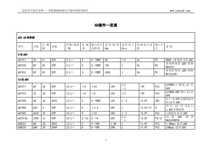
AD器件一览表
ADI AD 转换器
型号
8 位 ADC AD7574 AD7820
后缀
引脚 数
封装
JN 24
DIP
KN 20
DIP
AD7821
KN 20
DIP
12 位 ADC
AD7874
AN 28 DIP
AD7878
JN 28 DIP
三相电量测量 IC
3
沈阳单片机开发网——帮您精确掌握电子器件的使用细节
TI AD 转换器
器件
后缀
并行输出 AD 转换器
TLC0820A CN
THS1206 THS1408
CDA CPFB
串行输出 AD 转换器
TLC0838 TLV0838 TLC549 TLC549 TLV1544 TLC1549
20 8
8
8
8
8
16 10
8
10
16 10
20 10
16 10
20 10
20 12 20 12
±1.0 20
8
5
12.5 8 位 A/D 转换器
±1.0 37.9 8
3.3
50
低电压
±0.5 40
1
5
Y
12
8 位 A/D 转换器
±0.5 40
1
5
Y
12
8 位 A/D 转换器
±1.0 66
4
3.3
Y
Y
AD7777
AN
28 DIP
AD7861
AP
44 PLCC
AD7853L AN
ADM2486_CN

隔离型半双工RS-485收发器收发器————ADM248ADM24866一、功能描述ADM2486是ADI (Analog device,inc )公司推出的基于其专利iCoupler 磁隔离技术的隔离型RS-485收发芯片。
内部集成了三通道的数字隔离器、带三态输出的差分驱动器和一个带三态输入的RS485差分接收器。
节点数可允许多达50个,最高传输速率可达20M bps 。
iCoupler 磁隔离技术是ADI 公司的一项专利隔离技术,是一种基于芯片尺寸的变压器隔离技术,它采用了高速CMOS 工艺和芯片级的变压器技术。
所以,在性能、功耗、体积等各方面都有传统光电隔离器件(光耦)无法比拟的优势。
由于磁隔离在设计上取消了光电耦合器中影响效率的光电转换环节,因此它的功耗仅为光电耦合器的1/6--1/10,具有比光电耦合器更高的数据传输速率、时序精度和瞬态共模抑制能力。
同时也消除了光电耦合中不稳定的电流传输率,非线性传输,温度和使用寿命等方面的问题。
ADM2486具有限流和过热关断特性,能够防止输出短路,并防止出现由于总线争用而引起功耗过大的情况。
集成的热关断电路可将驱动器输出置为高阻状态,防止过度的功率损耗。
该芯片封装采用易于使用的SOW-16封装,工业级温度范围,无需任何分立元件就可实现RS-485通信功能。
二、性能特征�带隔离的RS-485收发器�隔离电压:2500Vrms �最高传输速率20Mbps �总线最大节点数:50个�热关断保护模式�支持PROFIBUS 总线�瞬态高共模抑制能力:25KV/μs �低功耗:逻辑侧1.0mA 工作电流�工作电压:V DD1:2.7~5.5V V DD2:4.75~5.25V�工作温度范围:-40℃--+85℃小封装:SOIC-16宽体图1,ADM2486功能框图三、应用范围�所有RS-485通信场合�需要电平转换器485通信�工业控制局域网�PROFIBUS总线隔离图2、ADM2486引脚功能图四、芯片引脚说明(如图2所示)引脚名称功能描述1V DD1逻辑端供电电源(2.7V~5.5V)2,8GND1逻辑端电源地(2脚、8脚内部已连接)3RxD接收输出,当RE(接收使能)为高电平时,此位禁止输出。
ADG408BRZ中文资料

Absolute Maximum Ratings ............................................................6 ESD Caution...................................................................................6
Rev. C
Information furnished by Analog Devices is believed to be accurate and reliable. However, no responsibility is assumed by Analog Devices for its use, nor for any infringements of patents or other rights of third parties that may result from its use. Specifications subject to change without notice. No license is granted by implication or otherwise under any patent or patent rights of Analog Devices. Trademarks and registered trademarks are the property of their respective owners.
The ADG408/ADG409 are improved replacements for the DG408/DG409 analog multiplexers.
FUNCTIONAL BLOCK DIAGRAMS
RN4905中文资料

― IC = −5mA, IB = −0.25mA
― VCE = −0.2V, IC = −5mA
― VCE = −5V, IC = −0.1mA
― VCE = −10V, IC = −5mA
― VCB = −10V, IE = 0
Min Typ. Max Unit
― ― −0.078 80 ― −0.6 −0.5 ― ―
― IC = 5mA, IB = 0.25mA
― VCE = 0.2V, IC = 5mA
― VCE = 5V, IC = 0.1mA ― VCE = 10V, IC = 5mA
― VCB = 10V, IE = 0, f = 1 MHz
Min Typ. Max Unit
―
―
100
nA
―
―
500
0.078 ― 0.145 mA
Characteristic
Collector cut-off current
Emitter cut-off current DC current gain Collector-emitter saturation voltage Input voltage (ON) Input voltage (OFF) Transition frequency Collector output capacitance
80
―
―
―
―
0.1 0.3
V
0.6
―
1.1
V
0.5
―
பைடு நூலகம்
0.8
V
―
250
― MHz
―
3
6
pF
Q1, Q2 Common Electrical Characteristics (Ta = 25°C)
uc3845中文资料应用
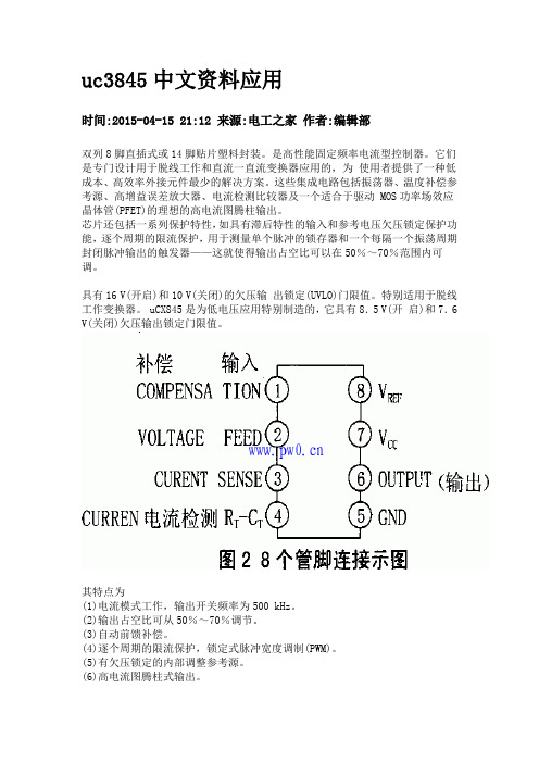
uc3845中文资料应用
时间:2015-04-15 21:12 来源:电工之家作者:编辑部
双列8脚直插式或14脚贴片塑料封装。
是高性能固定频率电流型控制器。
它们是专门设计用于脱线工作和直流一直流变换器应用的,为使用者提供了一种低成本、高效率外接元件最少的解决方案。
这些集成电路包括振荡器、温度补偿参考源、高增益误差放大器、电流检测比较器及一个适合于驱动 MOS功率场效应晶体管(PFET)的理想的高电流图腾柱输出。
芯片还包括一系列保护特性,如具有滞后特性的输入和参考电压欠压锁定保护功能,逐个周期的限流保护,用于测量单个脉冲的锁存器和一个每隔一个振荡周期封闭脉冲输出的触发器——这就使得输出占空比可以在50%~70%范围内可调。
具有16 V(开启)和10 V(关闭)的欠压输出锁定(UVLO)门限值。
特别适用于脱线工作变换器。
uCX845是为低电压应用特别制造的,它具有8.5 V(开启)和7.6 V(关闭)欠压输出锁定门限值。
其特点为
(1)电流模式工作,输出开关频率为500 kHz。
(2)输出占空比可从50%~70%调节。
(3)自动前馈补偿。
(4)逐个周期的限流保护,锁定式脉冲宽度调制(PWM)。
(5)有欠压锁定的内部调整参考源。
(6)高电流图腾柱式输出。
(7)带滞后的输入欠压锁定。
封装引脚图:
【互换兼容】
CS3845 CW3845 KA3885脚同(FA13845N)FA13845P L3845 LM3845 ST3845UC UC3845W UC3845N脚同UC3845A。
LA39系列按钮AD16系列规格书

LED
21-AC.DC 6V
r 22-AC.DC 12V
g
23-AC.DC 24V 24-AC.DC 36V
y 25-AC.DC 48V
w
26-AC.DC 110V 27-AC.DC 127V
b 28-DC 220V
31-AC 220V
32-AC 380V
LED 21-AC.DC 6V r 22-AC.DC 12V g 23-AC.DC 24V 24-AC.DC 36V y 25-AC.DC 48V w 26-AC.DC 110V 27-AC.DC 127V b 28-DC 220V 31-AC 220V 32-AC 380V
40 60 40 60
LA39-B2- M/ LA39-B2- MT/ LA39-B2- MD/ LA39-B2- MTD/
r g y k
LED
21-AC.DC 6V
22-AC.DC 12V
r
23-AC.DC 24V 24-AC.DC 36V
g 25-AC.DC 48V
y 26-AC.DC 110V 27-AC.DC 127V
LA39
22 LA39-(A)
LA39-A1- /
r
g
y
w
b
LA39-A1- T/
k
r
LA39-A1- / -H
g
y
w
b
LA39-A1- T/ -H
k
LA39-A1- D/ LA39-A1- TD/ LA39-A1- D/ -H LA39-A1- TD/ -H
LED
21-AC.DC 6V
r 22-AC.DC 12V
D T M MT
4
威力铭408MT技术描述和配置
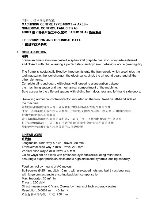
附件一: 技术描述和配置MACHINING CENTRE TYPE 408MT –7 AXES –NUMERICAL CONTROL FANUC 31i A5408MT型7轴铣车加工中心,配有FANUC 31iA5数控系统I. DESCRIPTION AND TECHNICAL DATAI. 描述和技术参数1 CONSTRUCTION结构Frame and main structure casted in spheroidal graphite cast iron, compartmentalized and closed, with ribs, ensuring a perfect static and dynamic behaviour and a great rigidity The frame is isostatically fixed by three points onto the framework, which also holds the tool magazine, the tool changer, the electrical cabinet, the all-round guard and all the other elements.Complete all-round guard with chips wall, ensuring a separation betweenthe machining space and the mechanical compartment of the machine.Safe access to the different spaces with sliding front door, rear and left-hand side doors.Swivelling numerical control director, mounted on the front, fixed on left-hand side of the machine.带加强筋间隔的铸铁床身,确保优良的静态和动态性能及强的刚性床身三点均衡的支承在机床钢框架上,同时也支撑着刀具库、换刀器、电器控制柜、封闭式防护罩和其他装置带有切削隔离墙的四周封闭式护罩,确保了加工区域和机械部分完全分开打开前边的滑动门、后门和右手边的门可直接安全的到达不同的区域旋转数控控制器安装在机器前边的左手边位置LINEAR AXES直线轴Longitudinal slide-way X-axis travel 250 mmTransversal slide-way Y-axis travel 200 mmVertical slide-way Z-axis travel 300 mmGuide-ways set on slides with preloaded cylindric recirculating roller pads,ensuring a super precision class and a high static and dynamic loading capacityFeed control by means of AC motors.Ball-screws Ø 25 mm, pitch 10 mm, with preloaded nuts and ball thrust bearingswith large contact angle ensuring backlash compensationMax. feedrate : 30 m/min.Thrust : 260 daNDirect measure on X, Y and Z-axes by means of high accuracy scalesResolution: 0.0001 mm (0.1um)X坐标轴水平导轨行程250 mmY坐标轴纵向导轨行程200 mmZ坐标轴垂直导轨行程300 mm在导轨上装有超精密级预紧的循环滚柱滑枕,确保了高精密度的高静态和动态的承载能力。
威索燃烧器中文说明书
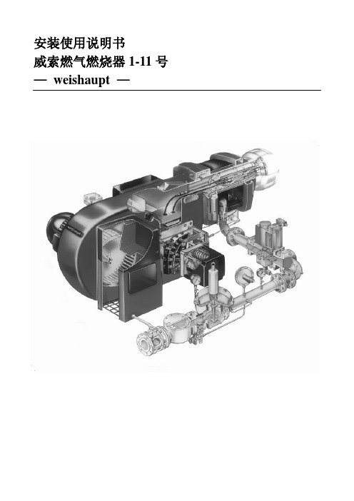
安装使用说明书威索燃气燃烧器1-11号—weishaupt —证明在此我们说明,威索(-weishaupt—)燃气燃烧器符合下列EC标准得基本要求:90/396/EEC Gas Equipment Guideline89/336/EWG Electromagnetic patibility73/23/EEC Low Voltage Guideline因此燃烧器上带有CE/0085标记。
其它质量保证体系由DIN EN ISO 9001认可。
德国麦克斯·威索有限公司目录1、一般说明 (2)2、燃烧器得安装 (4)3、气路示意图 (6)4、阀门组件说明 (7)5、阀门组件得安装 (14)6、阀门组件得气密性检验 (17)7、功能流程检验 (17)8、准备第一次调试 (18)9。
调试 (18)10.燃烧筒及稳焰盘得调整 (28)11、工作范围表 (29)12、设置点火电极 (30)13、鼓风轮得固定 (30)14.工作流程 (31)15、限制及辅助开关得凸轮位置设置 (38)16、燃气流量得计算,从标准状态到实际状态得换算 (40)17、常见故障及排除方法 (42)1、一般说明简介下表为安装及调试中各个步骤得基本概括为了达到正确安装及调试得目得,请对此说明书中得所有说明加以注意。
步骤工作章节1 燃烧器得安装 22 安装燃气阀门组 53 燃气阀门组得气密性检验 64 检查燃气供气压力8、15 排去燃气阀门组中得空气8、26 功能流程检验77 检查燃烧头108 检查设备9、19 调试9、3 安全性要确保燃烧器得安全运行,必须由合格得专业人员按此说明书进行正确得安装及调试.要特别注意相关得安全规定(如DIN—VDE,DIN —DVGW)。
火焰监测装置、限制装置,调节机构以及其它安全装置只能由制造厂或其委托单位进行安装.不遵守规定可能导致人员伤亡及重大物质损失等严重后果。
人员资格本说明书所指得合格人员为熟悉安装调试并有足够能力从事其工作得人员,如:➢受过培训,并有能力根据安全技术得标准操作、接地及标识电器得➢受过培训,并有能力在现场对燃气装置进行安装、调试及维修得操作说明每台燃烧器所附得操作说明必须放置在设备周围显眼处。
- 1、下载文档前请自行甄别文档内容的完整性,平台不提供额外的编辑、内容补充、找答案等附加服务。
- 2、"仅部分预览"的文档,不可在线预览部分如存在完整性等问题,可反馈申请退款(可完整预览的文档不适用该条件!)。
- 3、如文档侵犯您的权益,请联系客服反馈,我们会尽快为您处理(人工客服工作时间:9:00-18:30)。
ASCEND Semiconductor 4Mx4 EDO Data sheetDescriptionThe device CMOS Dynamic RAM organized as 4,194,304 words x 4 bits with extended data out access mode. It is fabricated with an advanced submicron CMOS technology and designed to operate from a single 3.3V oniy power supply. Low voltage operation is more suitable to be used on battery backup, portable elec-tronic application. lt is packaged in JEDEC standard 26/24-pin plastic SOJ or TSOP(II).Features• Single 3.3V(%) only power supply • High speed t RAC acess time: 50/60ns • Low power dissipation- Active mode : 432/396 mW (Mas) - Standby mode: 0.54 mW (Mas)• Extended - data - out(EDO) page mode access • I/O level: CMOS level (Vcc = 3.3V)• 2048 refresh cycle in 32 ms(Std.) or 128 ms(S-version)• 4 refresh modesh: - RAS only refresh- CAS - before - RAS refresh - Hidden refresh - Self-refresh(S-version)10±Pin Name FunctionA0-A10Address inputs- Row address - Column address - Refresh address DQ1~DQ4Data-in / data-out RAS Row address strobe CAS Column address strobe WE Write enable OE Output enable Vcc Power (+ 3.3V)VssGroundVCC 1DQ12DQ23DQ34DQ45VCC6891011 NC 12 WE 13A0 A117 A218 A319VSS RAS CAS OE A8A7A6A5A4VSSAD404M42VSPin Description Pin Configuration21222324 2526151416 A1026/24-PIN 300mil Plastic SOJA9VCC 1DQ12DQ23DQ34DQ45VCC6891011 NC 12 WE 13A0 A117 A218 A319VSS RAS CAS OE A8A7 A6A5 A4VSSAD404M42VT212223242526151416 A1026/24-PIN 300mil Plastic TSOP (ll)A9A0-A10A0-A10A0-A10WECASNO. 2 CLOCK GENERATORCOLUMN ADDRESS BUFFERS (11)REFRESH CONTROLLERREFRESH COUNTERBUFFERS (11)ADDRESS ROW NO. 1 CLOCK GENERATORA0RASA1A2A3A4A5A6A7A8CONTROLLOGICDATA-IN BUFFERDATA-OUT BUFFEROEDQ1.DQ4.COLUMN DECODER2048SENSE AMPLIFIERSI/O GATING2048x42048x2048x4MEMORY ARRAY2048R O W D E C O D E RVcc VssBlock DiagramA9A10TRUTH TABLENotes: 1. EARLY WRITE only.FUNCTIONRASCAS WE OE ADDRESSESDQ SNotesROW COL STANDBY H X X X X High-Z READL L H L ROW COL Data-Out WRITE: (EARLY WRITE )L L L X ROW COL Data-lnREAD WRITE L L ROW COL Data-Out,Data-ln EDO-PAGE-MODE READ1st Cycle L H L ROW COL Data-Out 2nd CycleL H L n/a COL Data-Out EDO-PAGE MODE WRITE1st CycleL L X ROW COL Data-In 2nd Cycle L L Xn/a COL Data-InEDO-PAGE-MODEREAD-WRITE 1st Cycle L ROW COL Data-Out, Data-In 2nd Cycle L n/a COL Data-Out, Data-In HIDDEN REFRESHREAD L H L ROW COL Data-Out WRITEL L X ROW COL Data-In 1RAS-ONLY REFRESH L H X X ROW n/a High-Z CBR REFRESHLHXXXHigh-ZH X →H L →L H →H L →H L →H L →H L →H L →H L →L H →H L →H L →L H→L H L →→L H L→→H L→Absolute Maximum RatingsRecommended DC Operating ConditionsCapacitanceTa = 25°C, V CC = 3.3V%, f = 1MHz Note: 1. Capacitance measured with effective capacitance measuring method. 2. RAS, CAS = V IH to disable Dout.ParameterSymbol Value Unit Voltage on any pin relative to Vss V T -0.5 to + 4.6V Supply voltage relative to Vss V CC -0.5 to + 4.6V Short circuit output current I OUT 50mA Power dissipation P D 1.0WOperating temperature T OPT 0 to + 70°C Storage temperatureT STG-55 to + 125°CParameter/Condition Symbol3.3 Volt VersionUnitMinTyp MaxSupply VoltageV CC 3.0 3.33.6V Input High Voltage, all inputs V IH 2.0-V CC + 0.3V Input Low Voltage, all inputsV IL-0.3-0.8VParameterSymbol Typ Max Unit Note Input capacitance (Address)C I1 -5pF 1Input capacitance (RAS, CAS, OE, WE)C I2-7pF 1Output capacitance(Data-in, Data-out)C I/O-7pF1, 210±DC Characteristics :(T a = 0 to 70°C, V CC = + 3.3V%, V SS = 0V)Parameter Symbol Test Conditions AD404M42V Unit Notes-5-6Min Max Min MaxOperating current I CC1RAS cyclingCAS, cyclingt RC = min-120-110mA1, 2Standby Current LowpowerS-versionI CC2LVTTL interfaceRAS, CAS = V IHDout = High-Z-0.5-0.5mACMOS interfaceRAS, -0.2VDout = High-Z-0.15-0.15mAStandardpowerversionLVTTL interfaceRAS, CAS = V IHDout = High-Z-2-2mACMOS interfaceRAS,-0.2VDout = High-Z-0.5-0.5mARAS- only refresh current I CC3RAS cycling, CAS = V IHt RC = min-120-110mA1, 2 EDO page mode current I CC4t PC = min-90-80mA1, 3CAS- before- RAS refresh current I CC5t RC = minRAS, CAS cycling-120-110mA1, 2Self- refresh current (S-Version)I CC8 - 550 - 55010±CAS V CC≥CAS V CC≥t RASS100µs≥µADC Characteristics :(T a = 0 to 70°C , V CC = +3.3V %, V SS = 0V)Notes:1. I CC is specified as an average current. It depends on output loading condition and cycle rate when the device is selected. I CC max is specified at the output open condition.2. Address can be changed once or less while RAS = V IL .3. For I CC4, address can be changed once or less within one EDO page mode cycle time.Parameter Symbol Test Conditions AD404M42VUnitNotes-5-6Min MaxMin MaxInput leakage current I LI + 0.3V -55-55Output leakage current I LO + 0.3V Dout = Disable -55-55Output high Voltage V OH I OH = -2mA 2.4- 2.4-V Output low voltage V OLI OL = +2mA-0.4-0.4V10±0V Vin V CC ≤≤µA 0V Vout V CC ≤≤µAAC Characteristics(T a = 0 to + 70°C , V cc = 3.3V %, V ss = 0V) *1, *2, *3, *4Test conditions• Output load: one TTL Load and 100pF (V CC = 3.3V %)• Input timing reference levels:V IH = 2.0V, V IL = 0.8V (V CC = 3.3V %)• Output timing reference levels:V OH = 2.0V, V OL = 0.8V10±10±10±Read, Write, Read- Modify- Write and Refresh Cycles (Common Parameters)ParameterSymbol AD404M42V UnitNotes-5-6Min MaxMin MaxRandom read or write cycle time t RC 84-104-ns RAS precharge timet RP 30-40-ns CAS precharge time in normal mode t CPN 10-10-ns RAS pulse width t RAS 50100006010000ns 5CAS pulse width t CAS 8100001010000ns 6Row address setup time t ASR 0-0-ns Row address hold time t RAH 8-10-ns Column address setup time t ASC 0-0-ns 7Column address hold time t CAH 8-10-ns RAS to CAS delay timet RCD 12371445ns 8RAS to column address delay time t RAD 10251230ns 9Column address to RAS lead time t RAL 25-30-ns RAS hold time t RSH 8-10-ns CAS hold timet CSH 38-40-ns CAS to RAS precharge time t CRP 5-5-ns 10OE to Din delay time t OED 12-15-ns Transition time (rise and fall)t T 150150ns 11Refresh periodt REF -32-32ms Refresh period (S- Version)t REF -128-128ms CAS to output in Low- Z t CLZ 0-0-ns CAS delay time from Din t DZC 0-0-ns OE delay time from Dint DZO-0-nsRead CycleWrite Cycle Parameter SymbolAD404M42V Unit Notes-5-6Min Max Min MaxAccess time from RAS t RAC-50-60ns12 Access time from CAS t CAC-14-15ns13, 14 Access time from column address t AA-25-30ns14, 15 Access time from OE t OEA-12-15nsRead command setup time t RCS0-0-ns7 Read command hold time to CAS t RCH0-0-ns10, 16 Read command hold time to RAS t RRH0-0-ns16 Output buffer turn-off time t OFF012015ns17 Output buffer turn-off time from OE t OEZ012015ns17Parameter SymbolAD404M42V Unit Notes -5-6Min Max Min MaxWrite command setup time t WCS0-0-ns7, 18 Write command hold time t WCH8-10-nsWrite command pulse width t WP8-10-nsWrite command to RAS lead time t RWL13-15-nsWrite command to CAS lead time t CWL8-10-nsData-in setup time t DS0-0-ns19 Data-in hold time t DH8-10-ns19 WE to Data-in delay t WED10-10-nsRead- Modify- Write CycleRefresh Cycle Parameter SymbolAD404M42V Unit Notes-5-6Min Max Min MaxRead-modify- write cycle time t RWC108-133-nsRAS to WE delay time t RWD64-77-ns18 CAS to WE dealy time t CWD26-32-ns18 Column address to WE delay time t AWD39-47-ns18 OE hold time from WE t OEH8-10-nsParameter SymbolAD404M42VUnit Notes -5-6Min Max Min MaxCAS setup time (CBR refresh) t CSR5-5-nsCAS hold time (CBR refresh)t CHR8-10-ns10 RAS precharge to CAS hold time t RPC5-5-ns7 RAS pulse width (self refresh)t RASS100-100-RAS precharge time (self refresh)t RPS90-110-nsCAS hold time (CBR self refresh)t CHS-50--50-nsWE setup time t WSR0-0-nsWE hold time t WHR10-10-nsµsEDO Page Mode CycleEDO Page Mode Read Modify Write CycleParameterSymbol AD404M42VUnit Notes-5-6Min MaxMin MaxEDO page mode cycle timet PC 20-25-ns EDO page mode CAS precharge time t CP 10-10-ns EDO page mode RAS pulse width t RASP 5010560105ns 20Access time from CAS precharge t CPA -30-35ns 10, 14RAS hold time from CAS precharge t CPRH 30-35-ns OE high hold time from CAS high t OEHC 5-5-ns OE high pulse widtht OEP 10-10-ns Data output hold time after CAS low t COH 5-5-ns Output disable delay from WEt WHZ 310310ns WE pulse width for output disable whenCAS hight WPZ7-7-nsParameterSymbol AD404M42V Unit Notes -5-6Min MaxMin MaxEDO page mode read- modify- write cycle CAS precharge to WE delay timet CPW 45-55-ns 10EDO page mode read- modify- write cycle timet PRWC56-68-nsNotes :1. AC measurements assume t T = 2ns.2. An initial pause of 100 is required after power up, and it followed by a minimum of eightinitialization cycles (RAS - only refresh cycle or CAS - before - RAS refresh cycle). If the internal refresh counter is used, a minimun of eight CAS - before - RAS refresh cycles are required.3. In delayed write or read-modify-write cycles, OE must disable output buffer prior to applying data to the device.4. All the V CC and V SS pins shall be supplied with the same voltages.5. t RAS (min) = t RWD (min)+t RWL (min)+t T in read-modify-write cycle.6. t CAS (min) = t CWD (min)+t CWL (min)+t T in read-modify-write cycle.7. t ASC (min), t RCS (min), t WCS (min), and t RPC are determined by the falling edge of CAS .8. t RCD (max) is specified as a reference point only, and t RAC (max) can be met with the t RCD (max) limit.Otherwise, t RAC is controlled exclusively by t CAC if t RCD is greater than the specified t RCD (max) limit. 9. t RAD (max) is specified as a reference point only, and t RAC (max) can be met with the t RAD (max) limit.Otherwise, t RAC is controlled exclusively by t AA if t RAD is greater than the specified t RAD (max) limit. 10. t CRP , t CHR , t RCH , t CPA and t CPW are determined by the rising edge of CAS .11. V IH (min) and V IL (max) are reference levels for measuring timing or input signals. Therefore, transitiontime is measured between V IH and V IL .12. Assumes that t RCD tRCD (max) and t RAD t RAD (max). If t RCD or t RAD is greater than the maximum recommended value shown in this table, t RAC exceeds the value shown. 13. Assumes that (max) and (max).14. Access time is determined by the maximum of t AA , t CAC , t CPA . 15. Assumes that (max) and (max). 16. Either t RCH or t RRH must be satisfied for a read cycle.17. t OFF (max) and t OEZ (max) define the time at which the output achieves the open circuit condition (highimpedance). t OFF is determined by the later rising edge of RAS or CAS.18. t WCS , t RWD , t CWD , and t AWD are not restrictive operating parameters. They are included in the datasheet as electrical characteristics only. If (min), the cycle is an early write cycle and the data out will remain open circuit (high impedance) throughout the entire cycle. If (min),(min), (min) and (min), the cycle is a read-modify-write and the data output will contain data read from the selected cell. If neither of the above sets of conditions is satisfied, the condition of the data output (at access time) is indeterminate.19. These parameters are referenced to CAS separately in an early write cycle and to WE edge in adelayed write or a read-modify-write cycle.20. t RASP defines RAS pulse width in EDO page mode cycles.µs ≤≤t RCD t RCD ≥t RADt RAD ≤t RCD t RCD ≤t RAD t RAD ≥t WCS t WCS ≥t RWD t RWD ≥t CWDt CWD ≥t AWD t AWD ≥t CPW t CPW≥Timing Waveforms• Read Cyclet RC t RASt RPtCRPtCPNtRRHtRCHt OEZ t OFF tOEA tCACt AAtRACt CLZD OUTtRCS t ASR tRAH tASC tCAH tRAD t RALtCAStRSH tRCDt TtCSHRASCASADDRESSWEDQ1~DQ4Note : = don’t care OEt OFFRowColumn= Invalid Dout•Early Write CycletRC t RASt RPt WCHt DSt DHt WCS t RALtCAStRSH tRCDt TtCSHRASCASWEDQ1~DQ4tCRPtASRtRAH tASCtCAH ADDRESSColumnRowtCPND INtRADt RAL• Delayed Write CycletRC t RASt RPt RWL t RCSt CAStRSH tRCDt TtCSHRASCAStASR tRAH tCAHADDRESSColumnRow tASC D INDQ1~DQ4WEtCRPtCPNt DHt DSt OEHt OEDOEt DSOPENt WPt CWL• Read - Modify - Write CycletRWC t RASt RPtRWDt WPtRADtRWL tCAStCWL tRCDt TtCPNRASCASWEtCRP t ASRtRAHtASCtCAHADDRESS Column RowDQ1~DQ4t DHt DSOEtRCStAWD tCWD D INt OEDt OEHt OEZt OEA t CAC t RACt AADQ1~DQ4D OUTOPENtDZCtDZO• EDO Page Mode Read CycletRASPtCPRHt RCStCAStRSH tRCDt OEAtCSHRASCAStASRtRAHtCAHADDRESStCASWEtCRPt CPOEDQ1~DQ4OPENtOEPD OUT 1t PCt CPtCAStCPNtCRPtRADtCAHtASCt ASCtCAHt ASCt RAL Row Column 1t OEAt OEHCtRRH tRCHt RACt AAt AAt AA t CPA t CPA t OEZt OFFt OFFt CACt OEZt CAC t CACt COHD OUT NWE OE Column 2Column N Rowt RPD OUT 2• EDO Page Mode Early Write CycletRASPtRPt WCSt CAStRSH tRCDRASCAStASRtRAHtCAHADDRESStCASWEt CPDQ1~DQ4t PCt CPt CAStCPNtCRP tCAH tASCtASC tCAH tASC Row Column 1t DS WE Column 2Column Nt WCH t WCS t WCH t WCS t WCHt DH t DS t DH t DS t DHD IN 1D IN 2D IN Nt TtCSH• EDO Page Mode Read-Early-Write Cyclet RASPtCPRHt RCStCAStRSH tRCDt OEAtCSHRASCAStASRtRAHtCAHADDRESStCASWEtCRPt CPOEDQ1~DQ4OPENtWEDt PCt CPtCAStCPNtCRPtRADtRAHtASCt ASCtCAHt ASCt RAL Row Column 1tWCStRCHt RACt AAt AAt CPA t DHt WHZt CACt CACt COHWE OE Column 2Column N Rowt RPt CAL tWCHDataDoutput 2Data Input NDataDoutput 1t DStCSH• EDO Page Mode Read-Modify-Write Cyclet RASPt CPRHt RCStCASt WP RASCASt ASRtRAHtCAHADDRESSt CASWEtRCDCPDQ1~DQ4tPRWCt CPtCAStCRPtRADtCAHtASCt ASCtCAH tASC Row Column 1tRWLtRCSt OEDt DZOt CAC WE OEt RPt RAL D OUT 2D OUT ND OUT 1tTt Column NColumn 2Column 1tRWD tAWD tCWDtCWLtRCStCWDtAWD tCPW tCWL tCPW tAWD tCWDtCWL t OEDt OEDt OEHt OEHt OEHt CAC t CAC t OEA t AAt RACt OEZt OEAt AA t CPAt OEZt OEAt AA t CPAt OEZ t DSt DHt WP t DSt DHt WP t DSt DHOPENOPENOPEN D IN 1D IN ND IN 2DQ1~DQ4t DZCt DZOt DZCt DZCt DZO• Read Cycle with WE Controlled Disablet WPZt RCStCAStRCDt TtCSHRASCASt ASRtRAHtCAHADDRESSColumnRow tASCD DQ1~DQ4WEt OEZt DSt WHZOEt RCH t OEA t CACt AAt RACt CLZOUTtRADRASADDRESSt RC t CRPt ASRt RAHt Tt RPCROWt OFFCAS t RASt RPOPENt CRPDQ1~DQ4RASt CSRt WSRt RPt T t RPCt OFFCAS t RASt RPOPENt CRPDQ1~DQ4t RPCt CHRt RASt RPt RCt RCt CHRt CSRt WHRt WSRt WHRWECAS-Before-RAS Refresh CycleRASWEt RPCt OFFt CSRt CHSt WSRCASt RASS t RPSOPENDQ1~DQ4t WHRHigh lmpedance• Hidden Refresh Cyclet RPt RASRASt RCDt CRPADDRESSWEt CHRt CASt RSHt RAHt ASRt ASCt CAHt RAL ROW t RCHt OEZCASDQ1~DQ4t Tt RCSD t RASt RASt RPt RPt RC t RCt RCt RADt RRHt OFF t OFFt OEA t CACt AAt RACCOlumnOUTOE(READ)(REFRESH)(REFRESH)Ordering informationAD404M42VSA-5• AD• Ascend Memory Product • 40 • Device Type• 4M4 • Density and Organization • 2• Refresh Rate, 2: 2K Refresh • V• T: 5V, V: 3.3V• S • Package Type (S : SOJ, T : TSOP II)• A• Version• 5• Speed (5: 50 ns, 6: 60 ns)Part Number Access time PackageAD404M42VSA-5AD404M42VSA-6AD404M42VTA-5AD404M42VTA-650 ns 60 ns 50 ns 60 ns300mil 26/24-Pin Plastic SOJTSOP IIPackaging information • 300 mil, 26/24-Pin Plastic SOJ• 300 mil, 26/24-Pin TSOP II。
