Two-Layer Planarization in Graph Drawing Petra Mutzel and Ren'e Weiskircher
graphical model解释
图形模型1. 介绍图形模型(Graphical Model)是一种用于描述随机变量之间依赖关系的工具。
它可以表示为一个图结构,其中节点表示随机变量,边表示变量之间的依赖关系。
图形模型在统计学、人工智能和机器学习等领域中得到广泛应用。
图形模型分为两大类:有向图模型(Directed Graphical Model)和无向图模型(Undirected Graphical Model)。
有向图模型也称为贝叶斯网络(Bayesian Network)或信念网络(Belief Network),无向图模型也称为马尔可夫随机场(Markov Random Field)。
2. 有向图模型有向图模型使用有向边来表示变量之间的因果关系。
节点表示随机变量,边表示变量之间的依赖关系。
每个节点都与其父节点相连,父节点的取值影响子节点的取值。
贝叶斯网络是一种常见的有向图模型。
它通过条件概率表来描述各个节点之间的依赖关系。
条件概率表定义了给定父节点取值时子节点取值的概率分布。
例如,假设我们要建立一个天气预测系统,其中包括三个变量:天气(Weather)、湿度(Humidity)和降雨(Rainfall)。
天气节点是根节点,湿度和降雨节点是其子节点。
贝叶斯网络可以表示为以下图结构:Weather -> HumidityWeather -> Rainfall其中,天气节点对湿度和降雨节点有直接影响。
我们可以通过条件概率表来描述这种影响关系。
3. 无向图模型无向图模型使用无向边来表示变量之间的相关关系。
边表示变量之间的相互作用,没有方向性。
每个节点都与其他节点相连,表示它们之间存在依赖关系。
马尔可夫随机场是一种常见的无向图模型。
它通过势函数来描述各个节点之间的依赖关系。
势函数定义了变量取值的联合概率分布。
例如,假设我们要建立一个人脸识别系统,其中包括三个变量:人脸(Face)、眼睛(Eyes)和嘴巴(Mouth)。
人脸节点是中心节点,眼睛和嘴巴节点与人脸节点相连。
计算机图形学课后习题答案
计算机图形学课后习题答案计算机图形学课后习题答案计算机图形学是一门研究计算机生成和处理图像的学科,它在现代科技和娱乐领域扮演着重要的角色。
在学习这门课程时,我们通常会遇到一些习题,用以巩固所学知识。
本文将提供一些计算机图形学课后习题的答案,希望能对大家的学习有所帮助。
1. 什么是光栅化?如何实现光栅化?光栅化是将连续的几何图形转换为离散的像素表示的过程。
它是计算机图形学中最基本的操作之一。
实现光栅化的方法有多种,其中最常见的是扫描线算法。
该算法通过扫描图形的每一条扫描线,确定每个像素的颜色值,从而实现光栅化。
2. 什么是反走样?为什么需要反走样?反走样是一种减少图像锯齿状边缘的技术。
在计算机图形学中,由于像素是离散的,当几何图形的边缘与像素格子不完全对齐时,会产生锯齿状边缘。
反走样技术通过在边缘周围使用不同颜色的像素来模拟平滑边缘,从而减少锯齿状边缘的出现。
3. 什么是光照模型?请简要介绍一下常见的光照模型。
光照模型是用来模拟光照对物体表面的影响的数学模型。
常见的光照模型有以下几种:- 环境光照模型:模拟环境中的整体光照效果,通常用来表示物体表面的基本颜色。
- 漫反射光照模型:模拟光线在物体表面上的扩散效果,根据物体表面法线和光线方向计算光照强度。
- 镜面反射光照模型:模拟光线在物体表面上的镜面反射效果,根据光线方向、物体表面法线和观察者方向计算光照强度。
- 高光反射光照模型:模拟光线在物体表面上的高光反射效果,通常用来表示物体表面的亮点。
4. 什么是纹理映射?如何实现纹理映射?纹理映射是将二维图像(纹理)映射到三维物体表面的过程。
它可以为物体表面增加细节和真实感。
实现纹理映射的方法有多种,其中最常见的是将纹理坐标与物体表面的顶点坐标关联起来,然后通过插值等技术将纹理映射到物体表面的每个像素上。
5. 什么是投影变换?请简要介绍一下常见的投影变换方法。
投影变换是将三维物体投影到二维平面上的过程。
常见的投影变换方法有以下几种:- 正交投影:将物体投影到一个平行于观察平面的平面上,保持物体在不同深度上的大小不变。
双三次b样条曲面与费格森曲面和双三次贝齐尔曲面的等价关系式
双三次b样条曲面与费格森曲面和双三次贝齐尔曲面的等价关系式双三次B样条曲面(Bi-Cubic B-Spline Surface)是一类基于多项式插值的曲面表示方法。
在计算机图形学、计算机辅助设计、机器视觉等领域中广泛应用。
而费格森曲面(Ferguson Surface)和双三次贝齐尔曲面(Bi-Cubic Bezier Surface)也是常见的曲面生成方法。
本文将介绍这三种曲面生成方法的等价关系式。
首先我们来介绍双三次B样条曲面。
B样条曲面是一种通过控制顶点来控制曲面形状的方法。
B样条曲面利用局部控制的特点,可以被看作是一种分段多项式曲面,因此具有一定的灵活性。
双三次B样条曲面是一种常用的B样条曲面表示方法,其控制点的方程用二阶分段多项式表示。
费格森曲面是另一种曲面表示方法,它采用二次多项式的形式表示曲面。
它的控制顶点包括四个点:一个内部点和三个连接该内部点的边界点。
费格森曲面对于局部变形和替换,具有一定的优势。
双三次贝齐尔曲面也是一种常用的曲面表示方法,其控制点方程用三次多项式表示。
通过控制顶点的变换,可以轻松地调整曲面的形状和平滑度。
关于这三种曲面表示方法的等价关系式,在很长一段时间内一直是一个研究热点。
事实上,它们之间有一定程度上的等价性。
具体而言,费格森曲面和双三次贝齐尔曲面都可以看作是双三次B样条曲面的一种特殊情况。
以费格森曲面为例,我们可以将其表示成如下形式:S(u,v) = [(1-u)^3P0 + 3u(1-u)^2P1 + 3u^2(1-u)P2 +u^3P3]× (1-v)^2+ [(1-u)^3Q0 + 3u(1-u)^2Q1 + 3u^2(1-u)Q2 + u^3Q3] × v^2+ 3[(1-u)^2P0 + 2u(1-u)P1 + u^2P2] × (1-v)^2v+ 3[(1-u)^2Q0 + 2u(1-u)Q1 + u^2Q2] × v^2(1-v)其中,P0、P1、P2、P3和Q0、Q1、Q2、Q3为角点坐标。
operation would result in non-manifold bodies
operation would result in non-manifold bodies在计算机图形学和几何建模领域,非流形体是指在三维空间中形状的一种特殊类型。
一个非流形体具有一个或多个不符合流形特性的区域。
流形是指一个无边界、表面光滑、内部无孔洞的物体,而非流形体则违反了这些性质。
非流形体在计算机图形学中经常出现,因为在建模和形状编辑过程中,一些操作可能会导致这种类型的物体。
下面是一些可能导致非流形体的操作:1. 重叠面:当一个物体的两个面共享相同的边或边集时,就会出现重叠面。
这可能是由于复制、移动或变形等操作导致的,会导致一个或多个非流形体形成。
2. 孔洞:一个非流形体可能有一个或多个孔洞,即在物体内部形成的空心区域。
这可能是由于布尔运算(如取交集、取并集)或其他形状编辑操作导致的。
3. 自交:自交是指一个物体的某个部分与其它部分相交。
这可能是由于旋转、拉伸、挤压等操作导致的,会导致非流形体的产生。
4. 嵌塞:嵌塞是指一个物体的某个部分被另一个物体或其自身部分所包围。
这可能是由于复制、移动、布尔运算等操作导致的。
5. 物体边界:非流形体的边界可能会有额外的不连续部分,即在其中一个顶点出现了一个无界的半边。
这种情况可以由于顶点的合并、分裂、删除等操作引起。
非流形体的存在可能会影响后续的计算和渲染过程。
例如,非流形体在进行体现场计算(CSG)和有限元分析时可能会导致错误的结果。
此外,在图形渲染过程中,非流形体可能会导致阴影、光照、纹理映射等效果的不准确或意外变化。
为了处理非流形体,通常需要进行修复操作,将其转换为流形体。
修复非流形体的方法有很多,一些常用的方法包括:1. 网格替代:通过重新生成一个流形网格替代非流形网格。
这可能涉及到重建表面或拓扑结构,以确保生成的网格符合流形特性。
2. 清理操作:通过一系列操作,例如顶点合并、边合并、面合并等,来清理非流形体中的不连续和重叠部分。
3. 网格修剪:通过删除非流形体中的不规则部分或孔洞,使其成为一个流形体。
完全二部多重图的Kp,q-因子分解的开题报告

完全二部多重图的Kp,q-因子分解的开题报告开题报告:完全二部多重图的Kp,q-因子分解一、研究背景和意义Kp,q-因子分解问题是一类常见的组合优化问题,其目标是将给定完全图中的所有边分解为两类因子:每个Kp所组成的因子和每个q-完全图所组成的因子。
Kp,q-因子分解在信息论和密码学中有广泛的应用,例如在网络编码和加密算法中。
完全二部多重图是一类特殊的图,其拥有相等的顶点集,但不同的边可以有不同的重量。
这使得完全二部多重图的Kp,q-因子分解问题变得更为复杂。
近年来,已有研究者对完全二部多重图的Kp,q-因子分解问题进行了初步的探究,但仍存在多个挑战和问题需要解决。
本研究旨在深入探究完全二部多重图的Kp,q-因子分解问题,研究其算法和理论分析,为信息论和密码学等领域提供更为完善和高效的解决方案。
二、研究内容和方法1. 研究完全二部多重图的Kp,q-因子分解问题的数学模型和约束条件,分析算法的可行性和时间复杂度。
2. 综合运用图论、组合数学和线性代数等相关知识,设计和实现高效的完全二部多重图的Kp,q-因子分解算法,并对算法进行理论分析。
3. 在理论计算基础上,实现并验证算法的正确性、可行性和效率,同时将算法与现有算法进行比较和优化。
4. 对算法的实验结果进行统计和分析,总结并提出完全二部多重图的Kp,q-因子分解问题在算法和理论上的研究进展和未来的研究方向。
三、预期成果和应用价值1. 本研究将提出一种更高效、更精确的完全二部多重图的Kp,q-因子分解算法,在时间、空间和能效等方面均具有较大的优势,可以满足信息论、密码学和其他相关领域对该算法的需求。
2. 本研究将深化对完全二部多重图的Kp,q-因子分解问题的数学模型、算法和理论分析的理解和应用,为相关领域提供更为科学和可靠的解决方案,从而更好地保护信息安全、提高数据传输效率等目的。
3. 本研究的成果将发表在相关领域的知名期刊或会议上,为学术界和工业界提供参考和借鉴,具有一定的理论和应用价值。
Boundary layer theory

Therefore, for flow over a flat plate, the pressure remains constant over the entire p plate (both inside and outside the boundary layer).
P.Talukdar/Mech-IITD
Temperature profiles for flow over an isothermal flat plate are similar like the velocity profiles. Thus, we expect a similarity solution for temperature to exist. Further, the thickness of the thermal boundary layer is proportional to
2
df/dη is replaced by θ
2 d 3f dη
3
2
+ Pr f
dθ = 0 dη
Compare For Pr = 1
+ f
d 2f dη
2
= 0
θ (0
)=
0 and θ (∞
)=
1
df = 0 dη η=0
and
df =1 dη η=∞
Thus we conclude that the velocity and thermal boundary layers coincide, and the nondimensional velocity and temperature profiles (u/u∞ and θ) are identical for steady, incompressible, laminar flow of a fluid with constant properties and Pr = 1 over an isothermal flat plate The value of the temperature gradient at the surface (Pr =1) ??
graphical model解释
图模型(Graphical Model)是一种用于表示和推断概率模型的图形化工具。
它是概率图论(Probabilistic Graphical Models)的一个重要分支,用于建模随机变量之间的概率依赖关系。
图模型将概率模型表示为图形结构,其中节点表示随机变量,边表示随机变量之间的依赖关系。
图模型主要用于处理不确定性问题,并在机器学习、人工智能、统计学等领域中得到广泛应用。
它提供了一种直观和紧凑的方式来描述复杂的概率模型,帮助人们更好地理解变量之间的相互作用和概率分布。
图模型可以分为两大类:贝叶斯网络(Bayesian Networks)和马尔可夫随机场(Markov Random Fields)。
贝叶斯网络:贝叶斯网络是一种有向图模型,其中节点表示随机变量,有向边表示条件概率依赖关系。
贝叶斯网络使用条件概率表来描述节点之间的依赖关系,其中每个节点的概率分布条件于其父节点的取值。
贝叶斯网络主要用于推断和预测问题,可以通过观测节点的值来推断其他节点的概率分布。
马尔可夫随机场:马尔可夫随机场是一种无向图模型,其中节点表示随机变量,无向边表示变量之间的条件独立性。
马尔可夫随机场使用势函数(Potential Function)来描述变量之间的关系,其中势函数的取值与节点及其邻居节点的取值有关。
马尔可夫随机场主要用于标注和分类问题,可以通过全局最优化方法来求解变量的最优配置。
图模型在概率推断、决策分析、模式识别等领域发挥着重要作用。
它提供了一种直观和可解释的方式来处理不确定性和复杂性问题,并在处理大规模数据和复杂系统时展现出优势。
一种新的低复杂度基于变换域的图像差错掩盖算法
一种新的低复杂度基于变换域的图像差错掩盖算法
王勤哲;胡波;裘荟荟
【期刊名称】《红外与毫米波学报》
【年(卷),期】2002(021)003
【摘要】针对图像视频在分组交换传输中的分组丢失问题,提出了一种低复杂度的、基于变换域的图像差错掩盖算法.在编码器端,采用分级编码技术,根据其对图像质量影响的大小将数据分成具有不同传输优先级的两组;在解码器端,根据丢失图像块的
性质,以及预测方法得到的阈值对其进行有效的差错掩盖.模拟结果显示,本算法有着更好的视觉质量以及更低的计算复杂度.
【总页数】5页(P200-204)
【作者】王勤哲;胡波;裘荟荟
【作者单位】复旦大学电子工程系,上海,200433;复旦大学电子工程系,上
海,200433;复旦大学电子工程系,上海,200433
【正文语种】中文
【中图分类】TN911
【相关文献】
1.一种新的鲁棒性、低复杂度超光谱图像压缩算法 [J], 邓家先;周开利
2.一种新的平移不变Shearlet变换域图像去噪算法 [J], 石满红;刘卫
3.一种基于变换域的图像压缩改进算法 [J], 王昆
4.一种基于粒子群优化的变换域彩色图像水印算法 [J], 李倩;崔新春;牛钰莹;丁家
琳
5.一种新的彩色图像变换域全息水印算法 [J], 李晨璐;孙刘杰
因版权原因,仅展示原文概要,查看原文内容请购买。
基于自转一阶非连续式微球双平盘研磨的运动学分析与实验研究
第53卷第8期表面技术2024年4月SURFACE TECHNOLOGY·133·基于自转一阶非连续式微球双平盘研磨的运动学分析与实验研究吕迅1,2*,李媛媛1,欧阳洋1,焦荣辉1,王君1,杨雨泽1(1.浙江工业大学 机械工程学院,杭州 310023;2.新昌浙江工业大学科学技术研究院,浙江 绍兴 312500)摘要:目的分析不同研磨压力、下研磨盘转速、保持架偏心距和固着磨料粒度对微球精度的影响,确定自转一阶非连续式双平面研磨方式在加工GCr15轴承钢球时的最优研磨参数,提高微球的形状精度和表面质量。
方法首先对自转一阶非连续式双平盘研磨方式微球进行运动学分析,引入滑动比衡量微球在不同摩擦因数区域的运动状态,建立自转一阶非连续式双平盘研磨方式下的微球轨迹仿真模型,利用MATLAB对研磨轨迹进行仿真,分析滑动比对研磨轨迹包络情况的影响。
搭建自转一阶非连续式微球双平面研磨方式的实验平台,采用单因素实验分析主要研磨参数对微球精度的影响,得到考虑圆度和表面粗糙度的最优参数组合。
结果实验结果表明,在研磨压力为0.10 N、下研磨盘转速为20 r/min、保持架偏心距为90 mm、固着磨料粒度为3000目时,微球圆度由研磨前的1.14 μm下降至0.25 μm,表面粗糙度由0.129 1 μm下降至0.029 0 μm。
结论在自转一阶非连续式微球双平盘研磨方式下,微球自转轴方位角发生突变,使研磨轨迹全覆盖在球坯表面。
随着研磨压力、下研磨盘转速、保持架偏心距的增大,微球圆度和表面粗糙度呈现先降低后升高的趋势。
随着研磨压力与下研磨盘转速的增大,材料去除速率不断增大,随着保持架偏心距的增大,材料去除速率降低。
随着固着磨料粒度的减小,微球的圆度和表面粗糙度降低,材料去除速率降低。
关键词:自转一阶非连续;双平盘研磨;微球;运动学分析;研磨轨迹;研磨参数中图分类号:TG356.28 文献标志码:A 文章编号:1001-3660(2024)08-0133-12DOI:10.16490/ki.issn.1001-3660.2024.08.012Kinematic Analysis and Experimental Study of Microsphere Double-plane Lapping Based on Rotation Function First-order DiscontinuityLYU Xun1,2*, LI Yuanyuan1, OU Yangyang1, JIAO Ronghui1, WANG Jun1, YANG Yuze1(1. College of Mechanical Engineering, Zhejiang University of Technology, Hangzhou 310023, China;2. Xinchang Research Institute of Zhejiang University of Technology, Zhejiang Shaoxing 312500, China)ABSTRACT: Microspheres are critical components of precision machinery such as miniature bearings and lead screws. Their surface quality, roundness, and batch consistency have a crucial impact on the quality and lifespan of mechanical parts. Due to收稿日期:2023-07-28;修订日期:2023-09-26Received:2023-07-28;Revised:2023-09-26基金项目:国家自然科学基金(51975531)Fund:National Natural Science Foundation of China (51975531)引文格式:吕迅, 李媛媛, 欧阳洋, 等. 基于自转一阶非连续式微球双平盘研磨的运动学分析与实验研究[J]. 表面技术, 2024, 53(8): 133-144.LYU Xun, LI Yuanyuan, OU Yangyang, et al. Kinematic Analysis and Experimental Study of Microsphere Double-plane Lapping Based on Rotation Function First-order Discontinuity[J]. Surface Technology, 2024, 53(8): 133-144.*通信作者(Corresponding author)·134·表面技术 2024年4月their small size and light weight, existing ball processing methods are used to achieve high-precision machining of microspheres. Traditional concentric spherical lapping methods, with three sets of circular ring trajectories, result in poor lapping accuracy. To achieve efficient and high-precision processing of microspheres, the work aims to propose a method based on the first-order discontinuity of rotation for double-plane lapping of microspheres. Firstly, the principle of the first-order discontinuity of rotation for double-plane lapping of microspheres was analyzed, and it was found that the movement of the microsphere changed when it was in different regions of the upper variable friction plate, resulting in a sudden change in the microsphere's rotational axis azimuth and expanding the lapping trajectory. Next, the movement of the microsphere in the first-order discontinuity of rotation for double-plane lapping method was analyzed, and the sliding ratio was introduced to measure the motion state of the microsphere in different friction coefficient regions. It was observed that the sliding ratio of the microsphere varied in different friction coefficient regions. As a result, when the microsphere passed through the transition area between the large and small friction regions of the upper variable friction plate, the sliding ratio changed, causing a sudden change in the microsphere's rotational axis azimuth and expanding the lapping trajectory. The lapping trajectory under different sliding ratios was simulated by MATLAB, and the results showed that with the increase in simulation time, the first-order discontinuity of rotation for double-plane lapping method could achieve full coverage of the microsphere's lapping trajectory, making it more suitable for precision machining of microspheres. Finally, based on the above research, an experimental platform for the first-order discontinuity of rotation for double-plane lapping of microsphere was constructed. With 1 mm diameter bearing steel balls as the processing object, single-factor experiments were conducted to study the effects of lapping pressure, lower plate speed, eccentricity of the holding frame, and grit size of fixed abrasives on microsphere roundness, surface roughness, and material removal rate. The experimental results showed that under the first-order discontinuity of rotation for double-plane lapping, the microsphere's rotational axis azimuth underwent a sudden change, leading to full coverage of the lapping trajectory on the microsphere's surface. Under the lapping pressure of 0.10 N, the lower plate speed of 20 r/min, the eccentricity of the holder of 90 mm, and the grit size of fixed abrasives of 3000 meshes, the roundness of the microsphere decreased from 1.14 μm before lapping to 0.25 μm, and the surface roughness decreased from 0.129 1 μm to 0.029 0 μm. As the lapping pressure and lower plate speed increased, the microsphere roundness and surface roughness were firstly improved and then deteriorated, while the material removal rate continuously increased. As the eccentricity of the holding frame increased, the roundness was firstly improved and then deteriorated, while the material removal rate decreased. As the grit size of fixed abrasives decreased, the microsphere's roundness and surface roughness were improved, and the material removal rate decreased. Through the experiments, the optimal parameter combination considering roundness and surface roughness is obtained: lapping pressure of 0.10 N/ball, lower plate speed of 20 r/min, eccentricity of the holder of 90 mm, and grit size of fixed abrasives of 3000 meshes.KEY WORDS: rotation function first-order discontinuity; double-plane lapping; microsphere; kinematic analysis; lapping trajectory; lapping parameters随着机械产品朝着轻量化、微型化的方向发展,微型电机、仪器仪表等多种工业产品对微型轴承的需求大量增加。
An Improved Heuristic Algorithm for UAV Path Planning in 3D Environment
An Improved Heuristic Algorithm for UAV Path Planning in 3D Environment Zhang Qi1, Zhenhai Shao1, Yeo Swee Ping2, Lim Meng Hiot3, Yew Kong LEONG4 1School of Communication Engineering, University of Electronic Science and Technology of China2Microwave Research Lab, National University of Singapore3Intelligent Systems Center, Nanyang Technological University4Singapore Technologye-mail:beijixing2006@,zhenhai.shao@, eleyeosp@.sg,emhlim@.sg, leongyk@Abstract—Path planning problem is one of core contents of UAV technology. This paper presents an improved heuristic algorithm to solve 3D path planning problem. In this study the path planning model is built based on digital map firstly, and then the virtual terrain is introduced to eliminate a significant amount of search space, from 3-Dimensions to 2-Dimensions. Subsequently the improved heuristic A* algorithm is applied to generate UAV trajectory. The algorithm is featured with various searching steps and weighting factor for each cost component. The simulation results have been done to validate the effectiveness of this algorithm.Keywords-unmanned aerial vehicle (UAV); path planning; virtual terrain; heuristic A* algorithmI.I NTRODUCTIONPath planning is required for an unmanned aerial vehicle (UAV) to meet the objectives specified for any military or commercial application. The general purpose of path planning is to find the optimal path from a start point to a destination point subject to the different operational constraints (trajectory length, radar exposure, collision avoidance, fuel consumption, etc) imposed on the UAV for a particular mission; if, for example, the criterion is simply to minimize flight time, the optimization process is then reduced to a minimal cost problem.Over decades several path planning algorithms have been investigated. Bortoff [1] presented a two-step path planning algorithm based on Voronoi partitioning: a graph search method is first applied to generate a rough-cut path which is thereafter smoothed in accordance with his proposed virtual-force model. Anderson et al. [2] also employed Voronoi approaches to generate a family of feasible trajectories. Pellazar [3], Nikolos et al. [4] and Lim et al. [5] opted for genetic algorithms to navigate the UAV. The calculus-of-variation technique has been adopted in [6]-[7] to find an optimal path with minimum radar illumination.In this paper, an improved heuristic algorithm is presented for UAV path planning. The path planning environment is built in section II, and the algorithm is depicted in section III, the following section presents experimental results which can validate the effectiveness of the proposed algorithm.II.P ATH PLANNING MODELSeveral factors must be taken into account in path planning problem: terrain information, threat information, and UAV kinetics. These factors form flight constraints which must be handled in planning procedure.Many studies use the mathematical function to simulate terrain environment [4]. This method is quick and simple, but compared with the real terrain which UAV flying across, it lacks of reality and universality. In this study, terrain information is constructed by DEM (digital elevation model) data, which is released by USGS (U.S. Geological Survey) as the true terrain representation.Threat information is also considered in path planning. In modern warfare, almost all anti-air weapons need radar to track and lock air target. Here the main threat is radar illumination. Radar threat density can be represented by radar equation, because the intrinsic radar parameters are determined before path planning. The threat density can be regarded inversely proportional to R4, where R is the distance from the UAV’s current location to a particular radar site.For simplicity, UAV is modeled as a mass point traveling at a constant velocity and its minimum turning radius is treated as a fixed parameter.III.P ATH PLANNING A PPRO A CHA.Virtual terrain for three-dimensional path planningUnlike ground vehicle routing planning, UAV path planning is a 3D problem in real scenario. In 3D space, not only terrain and threat information is taken into account, but also UAV specifications, such as max heading angle, vertical angle, and turning radius are incorporated for comprehensive consideration.The straightforward method for UAV path planning is partitioning 3D space as 3D grid and then some algorithms are applied to generate path. However, for any algorithm the computational time is mainly dependent on the size of search space. Therefore, for efficiency consideration, a novel concept of constructing a 2D search space which is based on original 3D search space is proposed, which is called virtual terrain. The virtual terrain is constructed above the real terrain according to the required flight safety clearance2010 Second International Conference on Intelligent Human-Machine Systems and Cyberneticsheight, as it is shown in Figure 1. . A’B’C’D’ is the real terrain and ABCD is virtual terrain. H is the clearance height between two surfaces. Virtual terrain enables path planning in 2D surface instead of 3D grid and can reduce search spaceby an order of magnitude.Figure 1. virtual terrain above real terrainB. Path planning algorithmA* algorithm [8]-[9] is a well-known graph search procedure utilizing a heuristic function to guide its search. Given a consistent admissible condition, A* search is guaranteed to yield an optimal path [8]. At the core of the algorithm is a list containing all of the current states. At each iterative step, the algorithm expands and evaluates the adjacent states of all current states and decides whether any of them should be added to the list (if not in the list) or updated (if already in the list) based on the cost function:()()()f n g n h n =+ (1)where f(n) is the total cost at the current vertex, g(n)denotes the actual cost from the start point to the current point n , and h(n) refers to the pre-estimated cost from the current point n to the destination point. For applications that entail searching on a map, the heuristic function h(n) is assigned with Euclidean distance.UAV path planning is a multi criteria search problem. The actual cost g(n) in this study is composed by three items: distance cost D(n), climb cost C(n) and threat cost T(n). So g(n) can be described as follows:()()()()g n D n C n T n =++ (2) Usually, the three components of g(n) are not treatedequally during UAV task. One or two is preferred to the others. We can achieve this by introducing a weighting factor w in (2).123()()()()g n w D n w C n w T n =++ (3) w i is weighting factor and 11mi i w ==∑. For example, ifthreat cost T(n) is for greater concern in particular task, the value of w i should be increased respectively.C. The improvement of path planning strategyVirtual terrain in part A enhanced computational efficiency by transforming 3D path planning space into 2D search plane. The further improvement can be achieved by applying a new developed strategy. The path planner expands and evaluates next waypoint in virtual terrain by this developed strategy is shown in Fig. 2, 3. This planning strategy employs various searching steps by defining a searching window which can represent the information acquired by UAV on board sensors. It enables different searching steps to meet different threat cost distribution. After searching window is set, UAV performance limits is imposed in searching window based on virtual terrain. Here the UAV performance limits include turning radius, heading and vertical angle. In Fig. 3, the point P(x, y, z) is current state, and the arrow represents current speed vector. The gray points show available states which UAV can reach innext step under the limits imposed by UAV performance.Figure 2.Searching windowFigure 3. Available searching states at P(x, y, z)IV. SIMULATIONSimulation is implemented based on section II andsection III. In this simulation, terrain data is read from USGS1 degree DEM. The DEM has 3 arc-second interval alonglongitude and latitude respectively. Also five radar threats are represented according radar equation in simulation environment. Here clearance height h is set 200 to definevirtual terrain. UAV maximal heading angle and vertical angle is 20。
西安交通大学17年9月课程考试《计算机图形学》作业考核试题
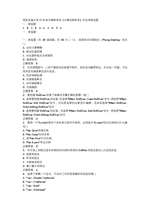
西安交通大学17年9月课程考试《计算机图形学》作业考核试题一、单选题1、B2、B3、A4、D5、A一、单选题一、单选题(共30 道试题,共60 分。
)V 1. 双线性法向插值法(Phong Shading)优点( )。
A. 法向计算精确B. 高光区域准确C. 对光源和视点没有限制D. 速度较快正确答案:B2. 在光照模型中,( )对于镜面光的处理不够好,会形成马赫带效应,针对这一问题,可以采用法向插值算法进行改进。
A. 恒定明暗处理B. 光强插值算法C. 法向插值算法D. 光线跟踪正确答案:B3. 要创建RollOver效果下面操作步骤正确的是哪一项( )A. 选择要创建RollOver的对象,先选择“Effect-RollOver-Creat RollOver”命令,再选择“Effect-RollOver-Edit RollOver”命令,对当前选择的对象进行编辑,完成后选择“Effect-RollOver-Finish Editing RollOver”命令B. 选择要创建RollOver的对象,先选择“Effect-RollOver-Edit RollOver”命令,再选择“Effect-RollOver-Finish Editing RollOver”命令正确答案:A4. 要将一个“Symbol”保存下来在其它软件中使用,必须选中“Symbol”后对文档进行什么操作( )A. “File-Save”存储文档B. “File-Close”关闭文档C. 曲“File-Print”打印文档D. “File-Export”导出文档正确答案:D5. 在平面上判断点是否在图形的内部时采用的Griffiths判别法是对( )方法的改进。
A. 角度判别法B. 符号判别法C. 半射线判别法D. 最小最大判别法正确答案:A6. 选择下面哪一个命令,可以在工作时获得最好的视觉效果( )A. “View-Simple Wireframe”B. “View-Wireframe”C. “View-Draft”D. “View-Enhanced”。
水平集算法在计算流体力学中的应用:综述
研究背景
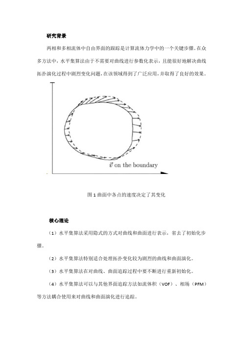
两相和多相流体中自由界面的跟踪是计算流体力学中的一个关键步骤。
在众多方法中,水平集算法由于不需要对曲线进行参数化表示,且能很好地解决曲线拓扑演化过程中剧烈变化问题,在该领域得到了广泛应用,并取得了良好的效果。
图1 曲面中各点的速度决定了其变化
核心理论
(1)水平集算法采用隐式的方式对曲线和曲面进行表示,省去了初始化步骤。
(2)水平集算法特别适合处理拓扑变化较为剧烈的曲线和曲面演化。
(3)水平集算法在对曲线、曲面追踪过程中要不断进行重新初始化。
(4)水平集算法可以与其他界面追踪方法如流体积(VOF)、相场(PFM)等方法耦合使用来对曲线和曲面演化进行追踪。
图2 基于水平集算法的曲线演化追踪方法
文章贡献
本文综述了水平集算法的基本原理和在计算流体力学自由界面跟踪中的应用。
包括曲线演化的理论基础、水平集算法中表示流体的偏微分方程的求解、两相流体自由界面跟踪、多相流体界面演化以及与其他方法耦合以提高跟踪性能的方法等。
在此基础上,证实了水平集方法单独或与其他算法耦合在流体界面跟踪中都可以取得良好的效果。
图3 固液气三相流中界面追踪
结论
水平集算法作为一种曲线演化的追踪方法,由于具有较高的计算精度,在数值计算和图像处理中得到了广泛的应用,并取得了良好的效果。
在两相流和多相流界面跟踪中,水平集算法同样具有重要的应用价值。
特别地,如果将水平集算法与其他方法(如流体积VOF)结合使用可以得到更好的结果。
基于对偶方法和局部统计信息的快速图像分割
pe io n p e r mpo e . x ei nsaemae o y tei i g s rcs n ad se dae i rv d E p r i me t r d n snht mae,muttre ojc ma e n dcli g swt ne sy c l— g t beti g sa d me ia mae i itni ia h t
Fa t m a eS g e t to s I g e m n a in
Ba e n Dua e ho nd Lo a t tsi nf r a i n sdo l M t d a c l a itcI o m to S
WA NG i u , I n Ha- n L U Mig j
一种基于二维拉格朗日连续水平集的图像分割方法
sg et t no e m n a i f ma e wih l w NR a u s i l me t d b h u e ia o u i n o h o f ce td f r n e o i g t o S v l e i mp e n e y t e n m rc l l to ft e c e f in i e e c s i f
Li J a l i u i n—e Fe - he ng Da z ng
( ol e C m ue, da nvri , ’n7 0 7 , hn ) C l g o p tr Xiin U ies y Xi 10 1 C ia e t a
( a o aKe a f a a i aP oes gX d nU i r t) in707 , hn) N t nl y b dr g l r s n, ii nv sy X ’ 10 1 C ia i L oR S n c i a ei a
m o e e s a c n i u u a a t i u c i n u i g t e l e c mbi a i n o wo di n i n La r n e b ss d l d a o t n o s p r me rc f n to sn h i o n n to ft — me so g a g a i.Th e d f r n ee u to sd rv d b n m ii g t e e e g r l to ri g e m e t t n. o s q e c , he i e e c q a i n i e i e y mi i z n h n r y f mu a i n f ma es g n a i f o o o Asa c n e u n e t m i i z to o h e e g o mu a i n s ie ty o t i e i t r n mi a i n f t e n r y f r l to i d r c l b a n d n e m o t e La r n e o f c e t Th a t f h g a g c e i n . i ef s
求解带二次约束的非凸二次规划的一种分支定界算法(英文)

求解带二次约束的非凸二次规划的一种分支定界算法(英文)杨永健;高岳林
【期刊名称】《应用数学》
【年(卷),期】2006(19)1
【摘要】本文提出了一种求解带二次约束和线性约束的二次规划的分支定界算法.在算法中,我们运用Lipschitz条件来确定目标函数和约束函数的在每个n矩形上的上下界,对于n矩形的分割,我们采用选择n矩形最长边的二分法,同时我们采用了一些矩形删除技术,在不大幅增加计算量的前提下,起到了加速算法收敛的效果.从理论上我们证明了算法的收敛性,同时数值实验表明该算法是有效的.
【总页数】5页(P25-29)
【关键词】二次规划;二次约束;分支定界;最优化
【作者】杨永健;高岳林
【作者单位】上海大学数学系
【正文语种】中文
【中图分类】O212.2
【相关文献】
1.一种新的求解带有非凸二次约束的非凸二次规划问题的加速全局优化方法 [J], 吴慧卓;段东东;张可村
2.线性约束非凸二次规划的有限分支定界算法 [J], 田朝薇;宋海洲
3.基于D.C.分解的一类箱型约束的非凸二次规划的新型分支定界算法 [J], 付文龙;
杜廷松;翟军臣
4.求解单二次约束非凸二次规划问题的全局最优DC算法 [J], 王建国;郑芳英;胡觉亮
5.一种新的二次约束二次规划问题的分支定界算法 [J], 黄小利;高岳林;谢金宵;谷剑峰
因版权原因,仅展示原文概要,查看原文内容请购买。
基于混合梯度最小化的铅笔画生成
基于混合梯度最小化的铅笔画生成王权;胡越黎;燕明;胡云生;陈朋【期刊名称】《上海大学学报(自然科学版)》【年(卷),期】2018(024)002【摘要】Algorithms for creating pencil drawing effect from an image have two major problems: details are often missing so that important edge lines are not clearly shown,and lines are monotonous without hierarchical information. To solve these problems,this paper proposes a pencil drawing generation algorithm based on hybrid gradient minimization. By combining L0gradient minimization and L1norm, prominent edges are maintained and enhanced without affecting the overall sharpness. This way, rich and hierarchical details in the image are fully retained. Experimental results indicate that the proposed method can generate high quality and more realistic pencil drawing effect. It is superior to several other existing method.%利用计算机模拟铅笔画生成的算法主要存在两个问题:其一是画面细节易丢失,边缘重点线条不够突出;二是笔画单一不能很好地展示原画中的层次信息.针对以上问题,提出了一种基于混合梯度最小化的铅笔画生成算法,通过结合L0梯度最小化和L1范数约束,既突出显示了图像边缘和重点线条,又不影响图像的整体锐度,同时可与原图像结构保持高度一致,充分展现了图像的层次性和丰富的细节信息.实验结果表明,本算法能够生成质量更高、真实感更强的的铅笔画效果,相比于已有的其他算法具有一定的优越性.【总页数】8页(P314-321)【作者】王权;胡越黎;燕明;胡云生;陈朋【作者单位】上海大学机电工程与自动化学院,上海200444;上海市电站自动化技术重点实验室,上海200072;上海大学机电工程与自动化学院,上海200444;上海市电站自动化技术重点实验室,上海200072;上海大学微电子研究与开发中心,上海200072;上海大学机电工程与自动化学院,上海200444;上海市电站自动化技术重点实验室,上海200072;上海大学机电工程与自动化学院,上海200444;上海市电站自动化技术重点实验室,上海200072;上海大学机电工程与自动化学院,上海200444;上海市电站自动化技术重点实验室,上海200072【正文语种】中文【中图分类】TP391【相关文献】1.一种基于小波变换的多尺度铅笔画生成算法 [J], 赵春晖;高冰2.基于多层次显著图的自动铅笔画生成 [J], 李瑞瑞;孙世豪;杨孝辉;胡伟3.基于混合梯度最小化Mumford-Shah模型的高维滤波算法 [J], 李波;苏卓;冷成财;王胜法;罗笑南4.基于显著性检测的局部彩色铅笔画生成算法 [J], 梁义涛;朱玲艳;孟亚敏;史卫亚5.基于显著性检测的局部彩色铅笔画生成算法 [J], 梁义涛;朱玲艳;孟亚敏;史卫亚因版权原因,仅展示原文概要,查看原文内容请购买。
图像分割之(二)GraphCut(图割)
图像分割之(⼆)GraphCut(图割)图像分割之(⼆)Graph Cut(图割)Graph cuts是⼀种⼗分有⽤和流⾏的能量优化算法,在计算机视觉领域普遍应⽤于前背景分割(Image segmentation)、⽴体视觉(stereo vision)、抠图(Image matting)等。
此类⽅法把图像分割问题与图的最⼩割(min cut)问题相关联。
⾸先⽤⼀个⽆向图G= 表⽰要分割的图像,V和E分别是顶点(vertex)和边(edge)的集合。
此处的Graph和普通的Graph稍有不同。
普通的图由顶点和边构成,如果边的有⽅向的,这样的图被则称为有向图,否则为⽆向图,且边是有权值的,不同的边可以有不同的权值,分别代表不同的物理意义。
⽽Graph Cuts图是在普通图的基础上多了2个顶点,这2个顶点分别⽤符号”S”和”T”表⽰,统称为终端顶点。
其它所有的顶点都必须和这2个顶点相连形成边集合中的⼀部分。
所以Graph Cuts中有两种顶点,也有两种边。
第⼀种顶点和边是:第⼀种普通顶点对应于图像中的每个像素。
每两个邻域顶点(对应于图像中每两个邻域像素)的连接就是⼀条边。
这种边也叫n-links。
第⼆种顶点和边是:除图像像素外,还有另外两个终端顶点,叫S (source:源点,取源头之意)和T(sink:汇点,取汇聚之意)。
每个普通顶点和这2个终端顶点之间都有连接,组成第⼆种边。
这种边也叫t-links。
上图就是⼀个图像对应的s-t图,每个像素对应图中的⼀个相应顶点,另外还有s和t两个顶点。
上图有两种边,实线的边表⽰每两个邻域普通顶点连接的边n-links,虚线的边表⽰每个普通顶点与s和t连接的边t-links。
在前后景分割中,s⼀般表⽰前景⽬标,t⼀般表⽰背景。
图中每条边都有⼀个⾮负的权值w e,也可以理解为cost(代价或者费⽤)。
⼀个cut(割)就是图中边集合E的⼀个⼦集C,那这个割的cost(表⽰为|C|)就是边⼦集C的所有边的权值的总和。
基于超图切割的半监督学习和聚类算法

基于超图切割的半监督学习和聚类算法
艾明
【期刊名称】《计算机测量与控制》
【年(卷),期】2024(32)5
【摘要】对超图切割上的半监督学习和聚类算法进行了研究;通过对超图切割和超边展开法及其切割函数的讨论,引入了超图上的总变异作为超图切割的洛瓦兹扩展,并在此基础上提出了一组正则化函数,它对应于图上的拉普拉斯型正则化;基于正则化函数族提出了半监督学习方法,并基于平衡超图切割提出了谱聚类方法;为了求解这两个学习问题,将它们转化为求解凸优化问题,并为此提出了一种主要组成部分为近端映射的可扩展算法,从而实现半监督学习和聚类;仿真实验结果表明,提出的基于超图切割实现的半监督学习和聚类方法相比于经典的超边展开法和其他图切割方法有更好的标准偏差和聚类误差性能。
【总页数】7页(P260-266)
【作者】艾明
【作者单位】郑州大学计算机与人工智能学院
【正文语种】中文
【中图分类】TP393.092
【相关文献】
1.基于概率超图半监督学习的专利文本分类方法研究
2.基于L0稀疏超图半监督学习的异常用电行为识别
3.基于半监督学习的K-均值聚类算法研究
4.基于联合半监督学习的大数据聚类算法
因版权原因,仅展示原文概要,查看原文内容请购买。
- 1、下载文档前请自行甄别文档内容的完整性,平台不提供额外的编辑、内容补充、找答案等附加服务。
- 2、"仅部分预览"的文档,不可在线预览部分如存在完整性等问题,可反馈申请退款(可完整预览的文档不适用该条件!)。
- 3、如文档侵犯您的权益,请联系客服反馈,我们会尽快为您处理(人工客服工作时间:9:00-18:30)。
Abstract. We study the two-layer planarization problems that have applications in Automatic Graph Drawing. We are searching for a two-layer planar subgraph of maximum weight in a given two-layer graph. Depending on the number of layers in which the vertices can be permuted freely, that is, zero, one or two, di erent versions of the problems arise. The latter problem was already investigated in 11] using polyhedral combinatorics. Here, we study the remaining two cases and the relationships between the associated polytopes. In particular, we investigate the polytope P1 associated with the twolayer planarization problem with one xed layer. We provide an overview on the relationships between P1 and the polytope Q1 associated with the two-layer crossing minimization problem with one xed layer, the linear ordering polytope, the two-layer planarization problem with zero and two layers xed. We will see that all facet-de ning inequalities in Q1 are also facet-de ning for P1 . Furthermore, we give some new classes of facet-de ning inequalities and show how the separation problems can be solved. First computational results are presented using a branch-and-cut algorithm. For the case when both layers are xed, the two-layer planarization problem can be solved in polynomial time by a transformation to the heaviest increasing subsequence problem. Moreover, we give a complete description of the associated polytope P2 , which is useful in our branch-and-cut algorithm for the one-layer xed case.
Two-Layer Planarization in Graph Drawing
Petra Mutzel and Rene Weiskircher
Max-Planck-Institut fur Informatik, Im Stadtwald, D-66123 Saarbrucken mutzel@mpi-sb.mpg.de, weiski@mpi-sb.mpg.de
1 Introduction
A bipartite graph is a graph G = (A; B; E ) with vertex sets A and B , called upper and lower layer, and an edge set E connecting a vertex in A with a vertex in B . There are no edges between two vertices in the same layer. A bipartite graph is two-layer planar G = (A; B; E ) if it can be drawn in such a way that all the vertices in A appear on a line (the upper line), the vertices in B appear on the lower line, and the edges are drawn as straight lines without crossing each other. The di erence between a planar bipartite graph and a two-layer planar bipartite graph is obvious. For example, the graph shown in Fig. 1 is a planar bipartite graph, but not a two-layer planar graph. Depending on the number of layers in which the permutation of the vertices is xed, di erent problems arise: { The permutations A and B of both layers A and B are xed: Given a two-layer graph G = (A; B; E; A ; B ) with weights we > 0 on the edges,
(a)
(b)
Fig. 1. (a) A planar bipartite graph that is (b) not 2-layer planar
the two-layer planarization problem (2 layers xed) is to extract a subgraph P G0 = (A; B; F; A ; B ), F E , of maximum weight, i.e., the sum e2F we is maximum, which contains no crossings with respect to the given permutations A and B . { The permutation A of one layer A is xed: Given a two-layer graph G = (A; B; E; A ; ) with weights we > 0 on the edges, the two-layer planarization problem (1 layer xed) is to extract a subgraph G0 = (A; B; F; A ; ), F E , of maximum weight, which contains no crossings with respect to the given permutation A of the upper layer. { Both layers can be permuted: Given a two-layer graph G = (A; B; E; ; ) with weights we > 0 on the edges, the two-layer planarization problem (none layer xed) is to extract a two-layer planar subgraph G0 = (A; B; F; ; ), F E , of maximum weight. To our knowledge, only the unweighted (we = 1 for all e 2 E ) two-layer planarization problems have been considered in the literature so far. Eades and Whitesides 4] showed NP-hardness for the latter two versions of the planarization problem and showed that the two ed by transforming it to a longest increasing subsequence problem. The none layer xed version was rst mentioned in 15]. The authors introduced the problem in the context of graph drawing. Recently, the weighted two-layer planarization problem has been attacked, in which the layers are allowed to be permuted freely 11]. The computational results are encouraging. Directed graphs are widely used to represent structures in many elds such as economics, social sciences, mathematics and computer science. A good visualization of structural information allows the reader to focus on the information content of the diagram. A common method for drawing directed graphs has been introduced by Sugiyama et al. 14] and Carpano 2]. In the rst step, the vertices are partitioned into a set of k layers, and in the second step, the vertices within each layer are permuted in such a way that the number of crossings is small. In practice, this is done layerwise. Keep the permutation of one layer x while permuting the other one, such that the number of crossings is reduced. We suggest an alternative approach for the second step. Already for two-layer graphs the straight-line crossing minimization problem is NP-hard 6] even if one layer is xed 5]. Exact algorithms based on branch and bound have been suggested by various authors (see, e.g., 9]). For k 2, a vast
