TSOP1736KA1中文资料
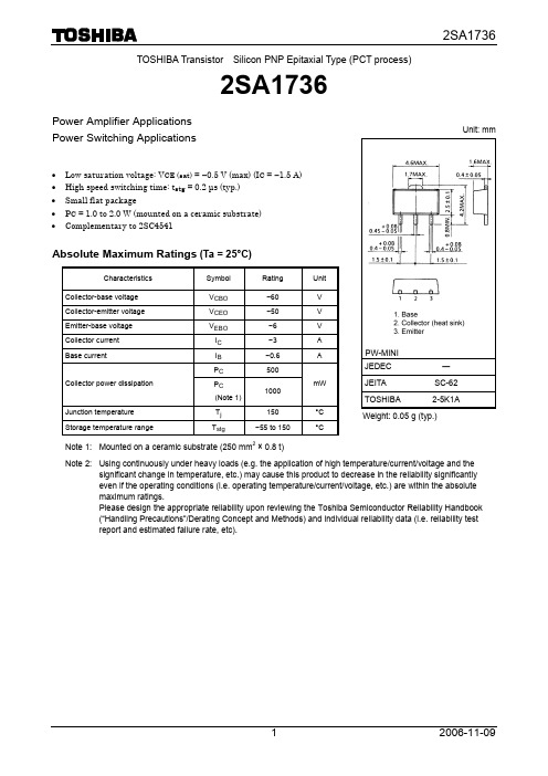
2SA1736中文资料
2SA1736
Power Amplifier Applications Power Switching Applications
2SA1736
Unit: mm
• Low saturation voltage: VCE (sat) = −0.5 V (max) (IC = −1.5 A) • High speed switching time: tstg = 0.2 μs (typ.) • Small flat package • PC = 1.0 to 2.0 W (mounted on a ceramic substrate) • Complementary to 2SC4541
3
2006-11-09
Collector current IC (A)
IC – VBE
−3.0 Common emitter
VCE = −2 V −2.5
−2.0
−1.5
Ta = 100°C
25
−25 −1.0
−0.5
0
0
−0.4
−0.8
−1.2
−1.6
−2.0
Base-emitter voltage VBE (V)
VCE (sat) – IC
−10
Common emitter
−3
IC/IB = 20
−1
−0.3
Ta = 100°C −0.1
−0.03
25 −25
−0.01 −1
−3 −10 −30 −100 −300 −1000 −3000
Collector current IC (mA)
Eaton Bussmann系列产品完整商品目录说明书

A c c e s s o r i e sContentssupplemental (midget)2Fuse reducers — Class J, H(K) and RDummy fuse "neutrals" — 1/4" x 1-1/4", UL supplemental (midget), Class CC, H(K) and R 3Fuse pullers Fuse testers Spare fuse holders 4Spare fuse cabinet Tron™ clip clamps DIN-Rail adapterBussmann series accessories to fit your needsFuse reducers and dummy “neutrals”Reducers for Class J fuses (DFJ, JKS, LPJ)Carton quantity: 10 pairJ-131-30100J-1635-60100J-2635-60200†J-2170-100200†J-4170-100400†J-42††110-200400†J-62110-200600†J-64225-400600†† Not for bolt-on applications.†† N ot compatible with JKS fuses.Reducers for Class H(K) and R fuses Agency information•UL Listed, Guide IZZR, File E12853•CSA Certified, Class 6225-01, File 47235Carton quantity: 10 pairNO.213NO.216Up to 30100NO.216NO.61635-60100NO.226NO.62635-60200NO.2621NO.262170-100200NO.2641†NO.2641†70-100400NO.2642NO.2642110-200400NO.2661†NO.2661†70-100600NO.2662†NO.2662†110-200600NO.2664†NO.2664†225-400600* Single reducer only, pair not required.† Not CSA Certified.SAMI™ fuse coversSAMI (Safety And Maintenance Improvement) fuse covers help improve electrical safety by shielding a fuse that's mounted in an open style block. They are available in indicating and non-indicating versions for fuse Classes CC, G, H(K), J, RK1, RK5 and T , as well as UL supplemental (midget-type) fuses. Indicating feature requires a minimum of 90 V to illuminate lamp.One cover required for each pole. WARNING: To avoid electrical shock, turn power off before installing, removing or servicing.Agency information•UL Listed; SAMI-1I through SAMI-6I and SAMI-9I, SAMI-1N through SAMI-6N and SAMI-9N•UL Recognized; Guide JDVS2, File E58836, SAMI-7I and SAMI-7N •CSA Certified, Class 6225-01, File LR47235•CEFeatures•Insulated cover isolate fuses mounted in open blocks•Optional open fuse indicating light aids in system troubleshooting •Units are re-usable•Allows visual marking of lineside and loadside of fusesSAMI-1N** 5.021.031.94250 V , RK, K5, H (35-60 A)SAMI-2_600 V , RK, K5, H (0-30 A)7.031.30 2.07SAMI-3_600 V , J (65-100 A)7.031.30 2.33SAMI-5_600 V , RK, K5, H (35-60 A)8.201.30 2.18SAMI-6_600 V , J (35-60 A)4.981.17 2.14SAMI-7_600 V , Midget, Class CC, G (0-30 A) 3.820.751.72SAMI-9_250 V , RK, K5, H (0-30 A) 3.820.751.72600 V T (0-30 A)* For indicating cover, add suffix “I”, for non-indicating cover, add suffix “N,”example: SAMI-7I = Indicating, SAMI-7N = Non-indicating.** A vailable only as non-indicating.Trimming guides, no. 12041, 12042, 12043, 12045, 12046, 12049Data sheet no. 1204Data Sheet: 1118Dummy fuse “neutrals”Fuse pullersFuse pullers are available in various sizes to help safely and easily extract fuses from blocks and holders. They are only to be usedwhen the associated circuit has been de-energized.FP-31" to 1-3/4" diameter. fuses FP-41-3/4" to 2-1/2" diameter. fuses FP-6Up to 60 A Class T fuses FP-A3Glass tube and ATC fuses CFP-30CUBEFuse up to 30 ACFP-60CUBEFuse 35-60 AProbes slide to appropriate fuse length. Batteries are included and replaceable.WARNING:DO NOT test fuses while they are in the fuse panel.FT-3Blade fuse tester* Replacement battery is Rayovac 364 or equivalent.FP-2CFP_FP-A3FP-6FP-4FP-3FT-3Note: These are not fusesNNB-R —Class CC —NNC —1/4" x 1-1/4”—NTN-R-30250Class R/H Up to 30NTN-R-60250Class R/H 35-60NTN-R-100250Class R/H 70-100NTN-R-200250Class R/H 110-200NTN-R-400250Class R/H 225-400NTN-R-600250Class R/H 450-600NTS-R-30600Class R/H Up to 30NTS-R-60600Class R/H 35-60NTS-R-100600Class R/H 70-100NTS-R-200600Class R/H 110-200NTS-R-400600Class R/H 225-400NTS-R-600600Class R/H450-600NTN-R-60NNB NNB-RNTN-R-200Spare fuse cabinetSFC locking spare fuse cabinet measures 24" W x 30" H x 12" D and has five cubic feet of storage space. It's constructed of heavy 16 gauge steel with durable baked ASA 61 grey enamelfinish. Cabinet door is equipped with locking handle for security. Mounting holes are 16 inches oncenter with key slots.SFC-SHELF*Extra shelf for cabinet 2A1910-1Replacement key 2A1910-3Replacement lockData sheet no. 1119Spare fuse holdersTPSFH spare fuse holders are durably constructed using thermoplastic and feature common mounting using #6 screws or bolts on 5-inchcenters. With built-in retaining clips to secure fuses, these dovetailed/interlocking holders simplify installation and reduce hardware needs. Common footprint allows for anycombination of holders to be mounted together.5TPH spare fuse holder for Class CC and 13/32" diameter fuses is constructed ofthermoplastic with adhesive tape on back for easy mounting on cabinet doors without the need for extra hardware.Flammability rating: UL 94V0TPSFH-M 4TPM fuses TPSFH-LC 1TPL-C series fuses TPSFH-LB 1TPL-B series fuses TPSFH-N601TPN (35-60 A) fuses TPSFH-N304TPN (1-30 A) fuses TPSFH-AS 6TPA and TPS fuses TPSFH-T 10GMT fuses5TPH5Class CC and 13/32" diameter fusesData sheet no. 5014TRON™ clip clampsClip clamps are constructed with a phenolic knob and plated-steel jaws. They provide a means of tightening the contact between fuse block clips and the fuse and are available in various sizes for both ferrule and blade-typecartridge fuse clips.NO.225035-60600Up to 30NO.460035-60NO.5250/60070-100NO.6250/600110-200NO.7250/600225-400NO.8250/600450-600DIN rail adapterA DIN-Rail adapter permitssecure, positive snap-on mounting of up to 30 amps fuse blocks (1-, 2-, or 3-pole) onto various size rails to eliminates costly and time consuming drilling, tapping, and fastener mounting. The adapter mechanically locks into mounting holes of fuse blocks to form an integral part. One adapter is required for 1- and 2-pole blocks. Two adapters are required for 3-pole blocks.With the exception of the 32mm DIN-Rail, all block/adapterassemblies can be removed from a rail simply by pulling up on the release tab.Use of rail end-stops on both sides of adapters is recommended.DRA-115mm (Sym.)32mm (Asym.)DIN 35mm (Sym.)Black13/32" x 1-1/2"10x38mmG H (250 V)†J (30 A, 60 A*)R (250 V)†* Not applicable for new modular fuse blocks that have built-in 35mm DIN-Rail mount capability.† Mounting on 15mm rails is not recommended.Package quantities•Standard 10•Bulk 100 (Cat. No. BK/DRA-1)。
TSOP34838;中文规格书,Datasheet资料

IR Receiver Modules for Remote Control SystemsMECHANICAL DATAPinning for TSOP348.., TSOP344..:1 = OUT, 2 = GND, 3 = V SPinning for TSOP322.., TSOP324..:1 = OUT, 2 = V S , 3 = GNDFEATURES•Very low supply current•Photo detector and preamplifier in one package •Internal filter for PCM frequency •Improved shielding against EMI •Supply voltage: 2.5 V to 5.5 V•Improved immunity against ambient light •Insensitive to supply voltage ripple and noise•Material categorization: For definitions of compliance please see /doc?99912DESCRIPTIONThese products are miniaturized receivers for infrared remote control systems. A PIN diode and a preamplifier are assembled on a lead frame, the epoxy package acts as an IR filter.The demodulated output signal can be directly decoded by a microprocessor. The TSOP348.., TSOP322.. are compatible with all common IR remote control data formats. The TSOP324.., TSOP344.. are optimized to suppress almost all spurious pulses from energy saving fluorescent lamps but will also suppress some data signals.This component has not been qualified according to automotive specifications.BLOCK DIAGRAMAPPLICATION CIRCUITPARTS TABLECARRIER FREQUENCY STANDARD APPLICATIONS(AGC2)VERY NOISY ENVIRONMENTS(AGC4)PINNING1 = OUT,2 = GND,3 = V S1 = OUT,2 = V S ,3 = GND1 = OUT,2 = GND,3 = V S1 = OUT,2 = V S ,3 = GND30 kHz TSOP34830TSOP32230TSOP34430TSOP3243033 kHz TSOP34833TSOP32233TSOP34433TSOP3243336 kHz TSOP34836TSOP32236TSOP34436TSOP3243638 kHz TSOP34838TSOP32238TSOP34438TSOP3243840 kHz TSOP34840TSOP32240TSOP34440TSOP3244056 kHzTSOP34856TSOP32256TSOP34456TSOP32456Note•Stresses beyond those listed under “Absolute Maximum Ratings” may cause permanent damage to the device. This is a stress rating only and functional operation of the device at these or any other conditions beyond those indicated in the operational sections of this specification is not implied. Exposure to absolute maximum rating conditions for extended periods may affect the device reliability.TYPICAL CHARACTERISTICS (T amb = 25 °C, unless otherwise specified)Fig. 1 - Output Active Low Fig. 2 - Pulse Length and Sensitivity in Dark AmbientABSOLUTE MAXIMUM RATINGSPARAMETER TEST CONDITIONSYMBOLVALUE UNIT Supply voltage V S - 0.3 to + 6V Supply current I S 3mA Output voltage V O - 0.3 to (V S + 0.3)V Output current I O 5mA Junction temperature T j 100°C Storage temperature range T stg - 25 to + 85°C Operating temperature range T amb- 25 to + 85°C Power consumption T amb ≤ 85 °C P tot 10mW Soldering temperaturet ≤ 10 s, 1 mm from caseT sd260°CELECTRICAL AND OPTICAL CHARACTERISTICS (T amb = 25 °C, unless otherwise specified)PARAMETER TEST CONDITION SYMBOLMIN.TYP.MAX.UNIT Supply current E v = 0, V S = 3.3 V I SD 0.270.350.45mA E v = 40 klx, sunlightI SH 0.45mA Supply voltage V S 2.55.5V Transmission distance E v = 0, test signal see fig. 1,IR diode TSAL6200,I F = 250 mA d 45m Output voltage low I OSL = 0.5 mA, E e = 0.7 mW/m 2,test signal see fig. 1V OSL 100mV Minimum irradiance Pulse width tolerance:t pi - 5/f 0 < t po < t pi + 6/f 0,test signal see fig. 1E e min.0.10.25mW/m 2Maximum irradiance t pi - 5/f 0 < t po < t pi + 6/f 0,test signal see fig. 1E e max.30W/m 2DirectivityAngle of half transmissiondistanceϕ1/2± 45degE eV O V VFig. 3 - Output Function Fig. 4 - Output Pulse Diagram Fig. 5 - Frequency Dependence of Responsivity Fig. 6 - Sensitivity in Bright AmbientFig. 7 - Sensitivity vs. Supply Voltage DisturbancesFig. 8 - Sensitivity vs. Electric Field DisturbancesEV O V V OL0.00.20.40.60.81.01.20.70.9 1.1 1.3f/f 0 - Relative Frequency16925E /E - R e l. R e s p o n s i v i t y e m i n.eFig. 9 - Max. Envelope Duty Cycle vs. Burst Length Fig. 10 - Sensitivity vs. Ambient TemperatureFig. 11 - Relative Spectral Sensitivity vs. WavelengthFig. 12 - Horizontal DirectivityFig. 13 - Sensitivity vs. Supply VoltageSUITABLE DATA FORMATThese products are designed to suppress spurious output pulses due to noise or disturbance signals. Data and disturbance signals can be distinguished by the devices according to carrier frequency, burst length and envelope duty cycle. The data signal should be close to the band-pass center frequency (e.g. 38 kH z) and fulfill the conditions in the table below.When a data signal is applied to the IR receiver in the presence of a disturbance signal, the sensitivity of the receiver is reduced to insure that no spurious pulses are present at the output. Some examples of disturbance signals which are suppressed are:•DC light (e.g. from tungsten bulb or sunlight)•Continuous signals at any frequency•Strongly or weakly modulated noise from fluorescent lamps with electronic ballasts (see figure 14 or figure 15)Fig. 14 - IR Signal from Fluorescent Lampwith Low ModulationFig. 15 - IR Signal from Fluorescent Lampwith High ModulationNote•For data formats with short bursts please see the datasheet for TSOP323.., TSOP325.., TSOP343.., TSOP345..0101520Time (ms)16920I R S i g n a l50101520Time (ms)16921I R S i g n a l5TSOP322.., TSOP348..TSOP324.., TSOP344..Minimum burst length10 cycles/burst 10 cycles/burst After each burst of lengtha minimum gap time is required of10 to 70 cycles ≥ 10 cycles 10 to 35 cycles ≥ 10 cycles For bursts greater thana minimum gap time in the data stream is needed of 70 cycles > 4 x burst length35 cycles> 10 x burst lengthMaximum number of continuous short bursts/second 18001500Recommended for NEC code yes yes Recommended for RC5/RC6 code yes yes Recommended for Sony codeyes no Recommended for Thomson 56 kHz codeyes yes Recommended for Mitsubishi code (38 kHz, preburst 8 ms, 16 bit)yes no Recommended for Sharp codeyesyesSuppression of interference from fluorescent lampsMost common disturbance signals are suppressedEven extreme disturbance signals are suppressedPACKAGE DIMENSIONS in millimetersLegal Disclaimer Notice VishayDisclaimerALL PRODU CT, PRODU CT SPECIFICATIONS AND DATA ARE SU BJECT TO CHANGE WITHOU T NOTICE TO IMPROVE RELIABILITY, FUNCTION OR DESIGN OR OTHERWISE.Vishay Intertechnology, Inc., its affiliates, agents, and employees, and all persons acting on its or their behalf (collectively,“Vishay”), disclaim any and all liability for any errors, inaccuracies or incompleteness contained in any datasheet or in any other disclosure relating to any product.Vishay makes no warranty, representation or guarantee regarding the suitability of the products for any particular purpose or the continuing production of any product. To the maximum extent permitted by applicable law, Vishay disclaims (i) any and all liability arising out of the application or use of any product, (ii) any and all liability, including without limitation special, consequential or incidental damages, and (iii) any and all implied warranties, including warranties of fitness for particular purpose, non-infringement and merchantability.Statements regarding the suitability of products for certain types of applications are based on Vishay’s knowledge of typical requirements that are often placed on Vishay products in generic applications. Such statements are not binding statements about the suitability of products for a particular application. It is the customer’s responsibility to validate that a particular product with the properties described in the product specification is suitable for use in a particular application. Parameters provided in datasheets and/or specifications may vary in different applications and performance may vary over time. All operating parameters, including typical parameters, must be validated for each customer application by the customer’s technical experts. Product specifications do not expand or otherwise modify Vishay’s terms and conditions of purchase, including but not limited to the warranty expressed therein.Except as expressly indicated in writing, Vishay products are not designed for use in medical, life-saving, or life-sustaining applications or for any other application in which the failure of the Vishay product could result in personal injury or death. Customers using or selling Vishay products not expressly indicated for use in such applications do so at their own risk and agree to fully indemnify and hold Vishay and its distributors harmless from and against any and all claims, liabilities, expenses and damages arising or resulting in connection with such use or sale, including attorneys fees, even if such claim alleges that Vishay or its distributor was negligent regarding the design or manufacture of the part. Please contact authorized Vishay personnel to obtain written terms and conditions regarding products designed for such applications.No license, express or implied, by estoppel or otherwise, to any intellectual property rights is granted by this document or by any conduct of Vishay. Product names and markings noted herein may be trademarks of their respective owners.Material Category PolicyVishay Intertechnology, Inc. hereb y certifies that all its products that are identified as RoHS-Compliant fulfill the definitions and restrictions defined under Directive 2011/65/EU of The European Parliament and of the Council of June 8, 2011 on the restriction of the use of certain hazardous substances in electrical and electronic equipment (EEE) - recast, unless otherwise specified as non-compliant.Please note that some Vishay documentation may still make reference to RoHS Directive 2002/95/EC. We confirm that all the products identified as being compliant to Directive 2002/95/EC conform to Directive 2011/65/EU.分销商库存信息: VISHAYTSOP34838。
TSOP1838中文手册
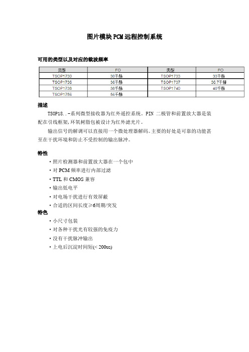
图片模块PCM远程控制系统可用的类型以及对应的载波频率描述TSOP18..-系列微型接收器为红外遥控系统。
PIN二极管和前置放大器是装配在引线框架,环氧树脂包被设计为红外滤光片。
输出信号的解调可以直接用一个微处理器解码。
主要的好处是可靠的功能甚至在干扰环境和防止不受控制的输出脉冲。
特性·照片检测器和前置放大器在一个包中·对PCM频率进行内部过滤·TTL和CMOS兼容·输出低电平·对电场干扰进行有效屏蔽·合适的区间长度≥6周期/突发特色·小尺寸包装·对各种干扰光有较强的免疫力·没有干扰脉冲输出·上电后沉淀时间短(< 200us)框图绝对最大额定值(amb T = 25℃)参数 测试条件 符号值单位 电源电压 (2脚) S V -0.3---6.0 V 电源电压 (2脚) S V 5mA 输出电压 (引脚3) O V -0.3---6.0 V 输出电流 (引脚3) O I 5 mA 结温J T100 ℃ 存储温度范围 stg T -25------85 ℃ 工作温度范围amb T -25------85 ℃ 耗电量 amb T ≤85℃ tot P 50 mW 焊接温度10≤t ssd T260℃基本特点( amb T = 25℃)参数测试条件符号 最小 典型 最大 单位 电源电流(引脚3)0v 5v ==E V S ,SD I0.9 1.2 1.5 mAklx 40,5==V S E V V sunlight SH I1.3 电源电压(引脚3) S V 4.5 5.5 V 传输距离 V E V 0=,测试信号参见图7d 35 m 输出电压(引脚1)o2e f f m /m 7.0E mA 5.0===,,W I O SLOSL V250mV辐照度(30至40KHZ) 脉冲宽度公差:o pi po o pi f t t f /6/4t +<<-min e E 0.3 0.5 2/m mW辐照度(56KHZ ) 0.4 0.7 辐照度max e E302m /W方向性 传输距离的半角 2/1φ45±deg应用电路*)建议,抑制电源干扰合适的数据格式TSOP18电路是这样设计的:避免由于噪声或干扰造成的异常输出脉冲。
不锈钢气源处理单元滤器系统说明书

不锈钢气源处理单元气源处理单元不锈钢警告,销售条件!ᅠ ᅠ警告本样本所述的产品和/或系统出现故障或选择不当或使用不当或相关物品可能导致死亡、人身伤害和财产损失。
本文件及其他信息由派克汉尼汾公司、其子公司及授权分销商提供产品和/或系统选项,供具有技术专长的用户进一步研究。
重要的是要分析一切你的应用场合的各个方面,包括任何失败的后果,并检查在当前产品样本有关产品或系统的信息。
由于这些产品或系统的操作条件和应用的多样性用户通过自己的分析和测试,全权负责产品和系统的最终选择能够满足应用场合的所有性能、安全和警告要求。
本样本中所述的产品,包括但不限于产品特性、规格、设计、可用性和价格,如有更改,派克汉尼汾公司及其附属公司可随时更改,恕不另行通知。
销售条件本样本中的产品由派克汉尼汾及分支机构,及授权经销商销售。
所有派克输入的销售合同,将遵守派克的销售标准条款。
(可提供复印件)内容气源处理单元不锈钢产品选型表 (1)空气过滤器微型PF504 .................................................................................................................................................2-3 标准型PF10 ..............................................................................................................................................4-5空气聚结式过滤器微型PF501 .................................................................................................................................................6-7 标准型PF11 ..............................................................................................................................................8-9空气减压阀微型PR354, PR364 ...............................................................................................................................10-11 标准型PR10, PR11 ...............................................................................................................................12-13空气过滤 / 减压阀微型PB548, PB558 ...............................................................................................................................14-15 标准型PB11, PB12 ...............................................................................................................................16-17 标准不锈钢过滤调压阀-主推产品....................................................................................................18-19油雾器标准型PL10 ...........................................................................................................................................20-21系列接口调压范围PSIG 页1/41/22560125250减压阀PR354X –标准标准标准—10-11PR364X –标准标准标准—PR10–X —标准标准可选12-13PR11–X—标准标准可选系列接口杯子杯子容量过滤精度(微米)调压范围PSIG 页1/41/2520402560125250过滤器/减压阀PB548X–316不锈钢 1 oz.可选标准—可选可选标准—14-15PB558X –316不锈钢1 oz.可选标准—可选 可选 标准—PB11–X 316不锈钢 4 oz.可选—标准—可选标准可选16-19PB12X X 316不锈钢 4 oz.可选—标准—可选标准可选油雾器PL10–X316不锈钢4 oz.20-21产品选型表基本单元系列接口杯子杯子容量过滤精度(微米)页1/41/252040过滤器PF504X–316不锈钢 1 oz.可选标准—2-3PF10–X 316不锈钢 4 oz.可选—标准4-5聚结式过滤器PF501X –316不锈钢 1 oz..3 Micron 6-7PF11–X 316不锈钢 4 oz..3 Micron10-11Remote Auto-Fill Device微型颗粒式过滤器气源处理单元不锈钢PF504系列,1/4接口PF504颗粒式过滤器 - 微型• 不锈钢结构可应对大多数腐蚀性环境• 氟橡胶密封标准• 符合NACE规范MR-01-75/ISO 15156• 1/8"内螺纹排水•1/4"接口(NPT, BSPP)常用型号接口AutomaticDrainManual Drain微型颗粒式过滤器气源处理单元不锈钢PF504系列,1/4接口流量曲线工作原理第一级过滤:空气从入口端进入并流经导流板(A),从而引起涡旋作用。
美国电子公司 Eaton 产品说明书

Eaton 191107Eaton Moeller® series MSC-DM DOL starter, 380 V 400 V 415 V: 0.75 kW, Ir= 1.6 - 2.5 A, 24 V DC, DC voltage MSC-DM-2,5-M7(24VDC)/MSFAGeneral specificationsEaton Moeller® series MSC-DM DOL starter191107MSC-DM-2,5-M7(24VDC)/MSFA4015081916054115 mm 180 mm 45 mm 0.767 kgUL 508 (on request)CSA-C22.2 No. 14 (on request)Product NameCatalog Number Model CodeEANProduct Length/Depth Product Height Product Width Product Weight CertificationsIs the panel builder's responsibility. The specifications for the switchgear must be observed.0.75 kW230 - 415 V AC0 A0 VMeets the product standard's requirements.Is the panel builder's responsibility. The specifications for the switchgear must be observed.Motor starter Feeder SystemDoes not apply, since the entire switchgear needs to be evaluated.0 kW0 kWMeets the product standard's requirements.24 VShort-circuit release0 V Save time and space thanks to the new link module PKZM0-XDM32ME Simple, flexible and safe! Distribution system for motor-starter combinationsMotor Starters in System xStart - brochureProduct Range Catalog Switching and protecting motorseaton-manual-motor-starters-msc-d-dol-starter-dimensions-005.eps eaton-general-ie-ready-dilm-contactor-standards.epseaton-manual-motor-starters-msc-d-dol-starter-3d-drawing-003.epsDA-CE-ETN.MSC-DM-2,5-M7(24VDC)_MSFAIL034030ZUIL015082ZUWIN-WIN with push-in technologyDA-CS-msc_dm_mfsaDA-CD-msc_dm_mfsaeaton-manual-motor-starters-device-msc-d-dol-starter-wiring-diagram.eps10.11 Short-circuit ratingRated operational power at AC-3, 380/400 V, 50 Hz Rated operational voltageRated conditional short-circuit current, type 1, 480 Y/277 V Rated control supply voltage (Us) at AC, 50 Hz - min10.4 Clearances and creepage distances10.12 Electromagnetic compatibilityMounting method10.2.5 LiftingRated power at 575 V, 60 Hz, 3-phaseRated power at 460 V, 60 Hz, 3-phase10.2.3.1 Verification of thermal stability of enclosures Rated control supply voltage (Us) at DC - minFitted with:Number of pilot lightsRated control supply voltage (Us) at AC, 50 Hz - max Coordination type BrochuresCatalogsDrawingseCAD model Installation instructions Installation videos mCAD modelWiring diagrams210.8 Connections for external conductorsIs the panel builder's responsibility.Coordination class (IEC 60947-4-3)Class 2Rated conditional short-circuit current, type 1, 600 Y/347 V0 AAmbient operating temperature - max55 °CRated operational power at AC-3, 220/230 V, 50 Hz0.37 kWConnection to SmartWire-DTNoNumber of command positionsElectrical connection type of main circuitScrew connectionElectrical connection type for auxiliary- and control-current circuit Screw connectionPower consumption (sealing) at DC2.6 WRated control supply voltage (Us) at DC - max24 V10.9.3 Impulse withstand voltageIs the panel builder's responsibility.Ambient operating temperature - min-25 °C10.6 Incorporation of switching devices and componentsDoes not apply, since the entire switchgear needs to be evaluated.10.5 Protection against electric shockDoes not apply, since the entire switchgear needs to be evaluated.ClassCLASS 10 A10.13 Mechanical functionThe device meets the requirements, provided the information in the instruction leaflet (IL) is observed.10.2.6 Mechanical impactDoes not apply, since the entire switchgear needs to be evaluated.10.9.4 Testing of enclosures made of insulating materialIs the panel builder's responsibility.10.3 Degree of protection of assembliesDoes not apply, since the entire switchgear needs to be evaluated.Actuating voltage24 V DCVoltage typeDCOverload release current setting - min1.6 ARated operational current (Ie)1.9 ASuitable forAlso motors with efficiency class IE3Number of auxiliary contacts (normally closed contacts)Rated conditional short-circuit current (Iq), type 2, 380 V, 400 V, 415 V50000 APower consumption2.6 W10.2.3.2 Verification of resistance of insulating materials to normal heatMeets the product standard's requirements.10.2.3.3 Resist. of insul. mat. to abnormal heat/fire by internal elect. effectsMeets the product standard's requirements.Overload release current setting - max2.5 A10.9.2 Power-frequency electric strengthIs the panel builder's responsibility.Overvoltage categoryIIIDegree of protectionIP20NEMA OtherPollution degree3Rated control supply voltage (Us) at AC, 60 Hz - min0 V10.7 Internal electrical circuits and connectionsIs the panel builder's responsibility.Rated impulse withstand voltage (Uimp)6000 V ACConnectionScrew terminals10.10 Temperature riseThe panel builder is responsible for the temperature rise calculation. Eaton will provide heat dissipation data for the devices.FunctionsTemperature compensated overload protectionRated conditional short-circuit current (Iq), type 2, 230 V 50000 ATypeStarter with Bi-Metal release10.2.2 Corrosion resistanceMeets the product standard's requirements.10.2.4 Resistance to ultra-violet (UV) radiationMeets the product standard's requirements.10.2.7 InscriptionsMeets the product standard's requirements.Short-circuit release (Irm) - max38.8 ARated control supply voltage (Us) at AC, 60 Hz - max0 VRated operational current (Ie) at AC-3, 380 V, 400 V, 415 V 2.5 AModelDirect starterNumber of auxiliary contacts (normally open contacts)1Eaton Corporation plc Eaton House30 Pembroke Road Dublin 4, Ireland © 2023 Eaton. All Rights Reserved. Eaton is a registered trademark.All other trademarks areproperty of their respectiveowners./socialmediaMax. 2000 m Altitude。
Eaton-低压电容补偿设备-产品目录.pdf说明书

简介■ 伊顿是一家全球动力管理公司,2018年销售额达216亿美元。
伊顿致力于提供多种节能高效的解决方案,以帮助客户更有效、更安全、更具可持续性地管理电力、流体动力和机械动力。
伊顿在全球拥有约10万名员工,产品销往超过175 个国家和地区。
伊顿库柏是一家具有着近两百年历史的全球性制造商,采用当今先进的生产设备、生产工艺监控和质量管控技术,严格按照国际质量标准进行生产,确保每一个出厂的产品都优质、值得信赖。
■ 旗下的电力传输与可靠性事业部,作为全球化制造商,具有优秀的市场领导力和技术创新,将电力安全可靠地输配至世界各地供电局、工业、商业场所、企事业单位和家庭。
可为配电设备安装、电力质量、断电管理、配电自动化、环境保护等领域,提供多种解决方案。
生产产品包括变压器、调压器、电力电容器、电缆附件、箱变配件、跌落式熔断器、隔离开关、柱上开关、环网柜、真空断路器、电力智能化解决方案等。
不仅广泛的应用到变电站、户外架空线路、地埋变、开关柜等智能输配电领域、而且还应用于铁路、太阳能和风能等领域。
■伊顿库柏电容器是电力传输与可靠性事业部的成员,在美国国内市场占有率超过50%,出口份额约占30%。
自从1946年成立以来,伊顿库柏电容器一直有优秀的技术发展,公司拥有国际认证的研发实验室,并拥有数十项专利技术。
■伊顿库柏低压无功补偿及滤波设备致力于为客户提供完整的无功补偿、谐波治理的解决方案。
广泛应用于铁路、矿山、冶金、石化、风电、制造业、商业楼宇、居民住宅等。
01库柏 CELC 低压电容器概述库柏 CELC 系列低压电容器采用金属化聚丙烯薄膜作为电介质绕制而成,具有低损耗、长寿命、自愈功能、带过压力隔离器、过流保护、高安全性等特点,钢质的箱体提高电容器的可靠性和安全性;为电力系统及工业用户提供世界最领先的技术、一流的品质以及卓越的服务。
库柏 CELC 系列低压电容器技术参数额定容量: 40~100kVar额定电压: 480V 525V 900V 频率:50/60Hz 过电流能力:在 130%的额定电流下安全运行过电压能力:在 110%的额定电压下安全运行介质损耗:介质损耗<0.1W/kVar,总损耗<0.25W/kVar 电容值偏差: -5 -- +10%内部放电电阻可于一分钟之内放电性能:将剩余电压至 50V 以下内部配置过压力分离器实现安全安全性能:保护功能内附熔丝,具有过电流保护电介质:电容器为干式自愈性,金属化聚丙烯薄膜CELC 低压电容器选型极间耐压: 2.15Un (额定电压) / 10s 极对壳耐压: 3.6kV/10s 海拔高压: < 4000m -防护等级: IP20环境温度: -40℃ –+55℃电容器安装容量安装方式:室内电容器额定电压 安装距离: ≥3cm 颜色:RAL 7035CELC 系列CELC 系列电容器标准型号电流 (A)有效容量 (kVar) CELC480-40 480 40 50 48 30 CELC480-50 480 50 50 60 37 CELC480-60 480 60 50 72 44 CELC480-70 480 70 50 84 52 CELC480-80 480 80 50 96 59 CELC480-100 480 100 50 120 74 CELC525-50 525 50 50 55 34 CELC525-80 525 80 50 88 54 CELC525-100 525 100 50 110 68 CELC900-80 900 80 50 51 50 CELC900-10090010050646202库柏CELCR系列低压电容器概述库柏CELCR系列低压电容器采用金属化聚丙烯薄膜作为电介质绕制而成,具有自愈功能、带过压力隔离器、尺寸小、高安全性等特点。
单片开关电源及其应用
单片开关电源及其应用TOPSwitch-LTOPSwitch-II系列单片电源—.TOPSwitch-LToPSWitCh-H系列单片电源器件单片开关电源具有单片集成化、最简外围电路、最佳性能指标、能构成无工频变压器开关电源等显著优点。
美国动力公司在世界上率先研制成功的三端隔离式脉宽调制单片开关电源集成电路,被誉为〃顶级开关电源〃。
TOPSwitch-I系列是美国动力公司1994年推出的第一代产品。
包括:TOP100-TOP104x TOP200-TOP204∕TOP214x TOP209∕TOP210o TOPSwitch-II则是在1997年推出的第二代产品。
第二代产品在电路性能,特别是输出功率上获得大幅度的提高。
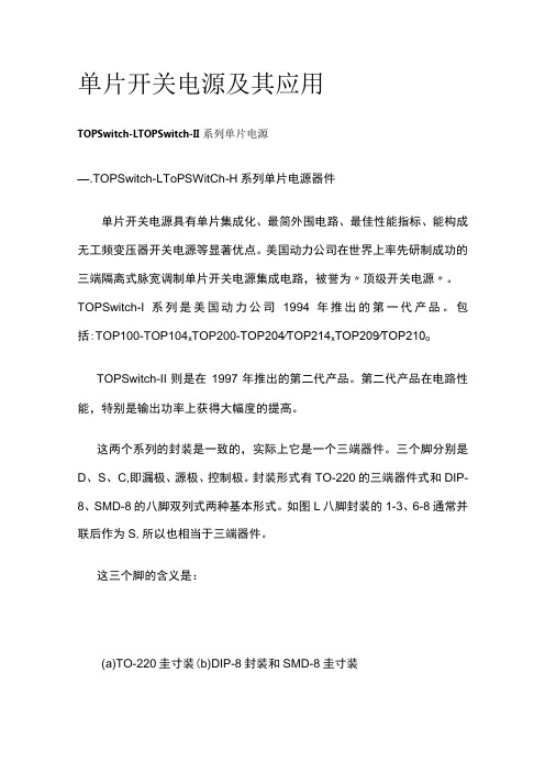
这两个系列的封装是一致的,实际上它是一个三端器件。
三个脚分别是D、S、C,即漏极、源极、控制极。
封装形式有TO-220的三端器件式和DIP-8、SMD-8的八脚双列式两种基本形式。
如图L八脚封装的1-3、6-8通常并联后作为S,所以也相当于三端器件。
这三个脚的含义是:(a)TO-220圭寸装(b)DIP-8封装和SMD-8圭寸装图1:TOPSwitch的封装源极S:连接内部MOSFET的源极,同时也是TOP开关及开关电源初级电路的公共接地点及基准点。
漏极D:是内部MOSFET的漏极,也是内部电流的检测点。
该点内部有一电流源提供芯片偏置电流。
控制极C:误差放大电路和反馈电流输入端。
其作用是:1)提供自动重启电容连接点并决定重启频率。
2)通过调节其输入电流,可以调整占空比。
3)为芯片提供正常工作的偏置电流。
4)提供旁路和补偿功能的电容连接点。
下面的介绍中,我们以TOPSWitCh-11为主。
二.ToPSWitCh-11产品的分类及特点(一)、产品分类TOPSwitch-11与第一代产品相比,它不仅在性能上进一步改进,而且输出功率得到显著提高,现已成为国际上开发中、小功率开关电源及电源模块的优选集成电路,其产品分类见表I o表1TOPSwitch-II的产品分类及最大输出功率P0M(单位:W)To—220封装(Y)DIP-8封装(P)/SMD—8封装(G)产品固定输入宽范产品型固定输入宽范型号(110/115/230V,AC,±15%)围输入(85V265V,AC)号(110/115/230V,AC,±15%)围输入(85V265V,AC)T0P2 21Y 127TOP221P 9/221G6T0P2 22Y 2515TOP222P 15/222G10T0P2 23Y 5030TOP223P 25/223G15T0P2 24Y 7545TOP224P 30/224G20T0P225Y10060T0P226Y12575T0P227Y15090(二)、性能特点1 .将脉宽调制(PWM)控制系统的全部功能集成到三端芯片中。
TSOP1838SF1中文资料
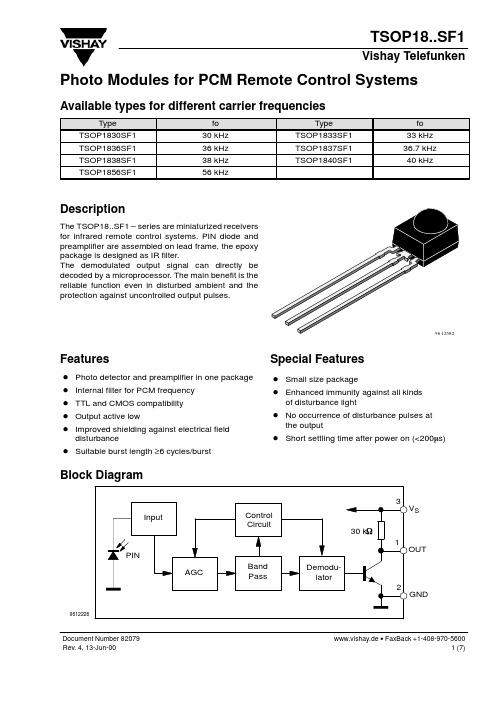
D Suitable burst length ≥6 cycles/burst
Block Diagram
3 Input Control Circuit 30 kW 1 PIN AGC Band Pass Demodulator 2
9612226
VS
OUT
GND
Document Number 82079 Rev. 4, 13-Jun-00
Special Features
D Small size package D Enhanced immunity against all kinds
of disturbance light
D No occurrence of disturbance pulses at D Short settling time after power on (<200ms)
Description
The TSOP18..SF1 – series are miniaturized receivers for infrared remote control systems. PIN diode and preamplifier are assembled on lead frame, the epoxy package is designed as IR filter. The demodulated output signal can directly be decoded by a microprocessor. The main benefit is the reliable function even in disturbed ambient and the protection against uncontrolled output pulses.
TSOP1736中文资料
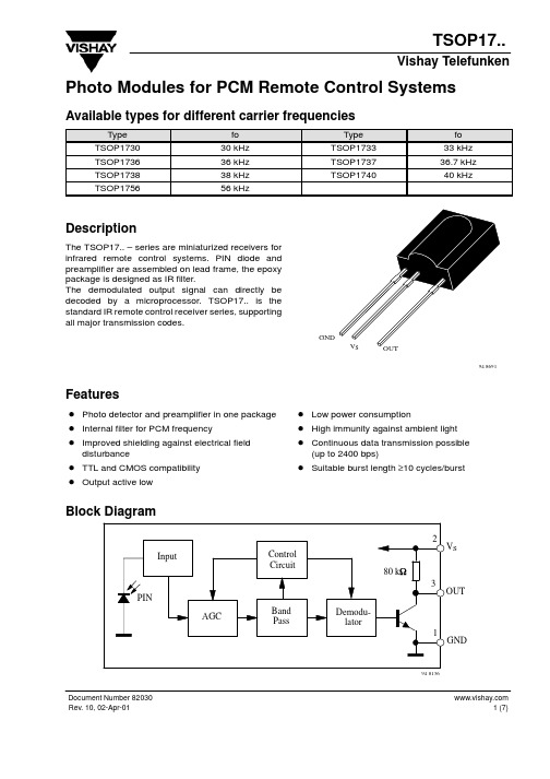
Ev = 0, test signal see fig.7, IR diode TSAL6200, IF = 400 mA Output Voltage Low (Pin 3) IOSL = 0.5 mA,Ee = 0.7 mW/m2, f = fo, tp/T = 0.4 Irradiance (30 – 40 kHz) Pulse width tolerance: tpi – 5/fo < tpo < tpi + 6/fo, test signal (see fig.7) Irradiance (56 kHz) Pulse width tolerance: tpi – 5/fo < tpo < tpi + 6/fo, test signal (see fig.7) Irradiance tpi – 5/fo < tpo < tpi + 6/fo Directivity Angle of half transmission distance
2 (7)
Document Number 82030 Rev. 10, 02-Apr-01
元器件交易网
TSOP17..
Vishay Telefunken Suitable Data Format
The circuit of the TSOP17.. is designed in that way that unexpected output pulses due to noise or disturbance signals are avoided. A bandpassfilter, an integrator stage and an automatic gain control are used to suppress such disturbances. The distinguishing mark between data signal and disturbance signal are carrier frequency, burst length and duty cycle. The data signal should fullfill the following condition: • Carrier frequency should be close to center frequency of the bandpass (e.g. 38kHz). • Burst length should be 10 cycles/burst or longer. • After each burst which is between 10 cycles and 70 cycles a gap time of at least 14 cycles is neccessary. • For each burst which is longer than 1.8ms a corresponding gap time is necessary at some time in the data stream. This gap time should have at least same length as the burst. • Up to 1400 short bursts per second can be received continuously. Some examples for suitable data format are: NEC Code, Toshiba Micom Format, Sharp Code, RC5 Code, RC6 Code, R–2000 Code, Sony Format (SIRCS). When a disturbance signal is applied to the TSOP17.. it can still receive the data signal. However the sensitivity is reduced to that level that no unexpected pulses will occure. Some examples for such disturbance signals which are suppressed by the TSOP17.. are: • DC light (e.g. from tungsten bulb or sunlight) • Continuous signal at 38kHz or at any other frequency • Signals from fluorescent lamps with electronic ballast (an example of the signal modulation is in the figure below).
CS 1716A使用手册

KVMP 切換器CS1708A / CS1716A 使用者說明書CS1708A / CS1716A User Manualvi 熱插拔 (19)變更機台位置 (19)熱插拔電腦連接埠 (19)熱插拔控制端連接埠 (19)連接埠選擇 (20)手動切換 (20)連接埠編號方式 (20)電源關閉與重新啟動 (21)USB周邊裝置 (21)第四章 (23)OSD操作 (23)OSD介紹 (23)OSD登入 (23)OSD熱鍵 (23)OSD主選單 (24)OSD主選單標頭 (25)OSD操作 (25)OSD功能鍵介紹 (26)F1 GOTO: (26)F2 LIST: (27)F3 SET (28)F4 ADM (30)F5 SKP (33)F6 BRC (34)F7 SCAN (35)F8 LOUT (36)第五章 (37)鍵盤操作 (37)鍵盤連接埠控制 (37)啟動熱鍵模式 (38)選擇切換連接埠 (39)自動掃描 (40)啟動自動掃描 (40)快速瀏覽模式 (41)電腦鍵盤/滑鼠重置 (42)熱鍵蜂鳴控制 (42)快速熱鍵控制 (43)OSD熱鍵控制 (43)連接埠作業系統控制 (44)恢復預設值 (44)熱鍵簡表 (45)第六章 (47)鍵盤模擬 (47)CS1708A / CS1716A User Manual Mac鍵盤 (47)Sun鍵盤 (48)第六章 (49)韌體升級功能 (49)介紹 (49)下載韌體升級套件 (49)更新前準備 (50)開始更新 (51)升級成功 (53)升級失敗 (53)韌體升級回復 (54)附錄 (55)安全指示 (55)一般 (55)機架安裝 (57)技術支援 (58)全球 (58)北美 (58)產品規格表 (59)CS1708A / CS1716A連接表 (60)CS1708A (60)CS1716A (60)支援的KVM切換器 (61)恢復原始的工廠預設值 (62)OSD工廠預設值 (63)關於SPHD連接頭 (63)疑難排除 (64)介紹 (64)保固條件 (64)vii第一章介紹產品介紹CS1708A / CS1716A為KVM切換器,為一組控制裝置,其允許從一組控制端(鍵盤、螢幕、滑鼠)存取多台電腦。
Eaton DE1可变速启动器177367商品说明说明书
Eaton 177367Eaton DE1 Variable speed starter, Rated operational voltage 400 V AC, 3-phase, Ie 3.6 A, 1.5 kW, 2 HPEaton DE1 Variable speed starter 1773674015081718276169 mm 230 mm 45 mm 1 kgIEC/EN61800-3 RoHS, ISO 9001 CEUL File No.: E172143 IEC/EN 61800-3UL report applies to both US and Canada IEC/EN61800-5 ULCertified by UL for use in Canada CSA-C22.2 No. 14 RCMSafety requirements: IEC/EN 61800-5-1 Specification for general requirements: IEC/EN 61800-2 UL 508CUL Category Control No.: NMMS, NMMS7 CULOverload cycle for 60 s every 600 sProduct NameCatalog Number EANProduct Length/Depth Product Height Product Width Product Weight Certifications Catalog Notes480 V3.6 A3.4 AIs the panel builder's responsibility. The specifications for the switchgear must be observed.400 V AC, 3-phase480 V AC, 3-phaseMeets the product standard's requirements.1.5 kW500 VMeets the product standard's requirements.-40 °C380 VPC connection0 Hz50 °C200 %, IH, max. starting current (High Overload), For 1.875 seconds every 600 seconds, Power section3.6 A Drives - Product range catalogeaton-frequency-inverter-dimensions-009.epseaton-frequency-inverter-3d-drawing-017.epsHVAC, water/wastewater and industrial mediums - brochure Number 1 in efficiency The easiest way of variable motor speed PowerXL DE1 Variable Speed StarterIL040005ZUMN040011_ESDA-CS-de1_fs1_ip20DA-CD-de1_fs1_ip20Quick-Start-Guide DE1 (english)Set point settingHow does the internal motor protection work?Quick-Start-Guide DE11 (english)Starting, Stopping and OperationThe OP System Bus - Parameterizing - ControlAccess to Parameter Level 2 Parameter Lock Load Default Motor data Motor Protection V/f curves Slip CompensationI/O ConfigurationConformal CoatingFire modeDX-COM-STICK3_ConnectionUpdate DX-COM-STICK3DA-DC-00004551.pdfDA-DC-00004556.pdfMains voltage - maxRated operational current for specified heat dissipation (In) Assigned motor current IM at 440 - 480 V, 60 Hz, 150% overload 10.11 Short-circuit ratingRated operational voltage10.4 Clearances and creepage distancesOutput at quadratic load at rated output voltage - maxOutput voltage - max10.2.3.1 Verification of thermal stability of enclosuresAmbient storage temperature - minMains voltage - minFitted with:Output frequency - minAmbient operating temperature at 150% overload - max Starting current - maxAssigned motor current IM at 230 V, 50 Hz, 150% overload Ambient operating temperature - max CatálogosDibujosFolletosInstrucciones de instalación Manuales y guías de uso mCAD modelNotas de aplicación Reportes de certificaciones60 °CCommunication interfaceModbus RTU, built inOP-Bus (RS485), built inAssigned motor power at 115/120 V, 60 Hz, 1-phase2 HPOutput frequency - max300 HzOutput voltage (U2)480 V AC, 3-phase400 V AC, 3-phaseSwitching frequency16 kHz, 4 - 32 kHz adjustable (audible), fPWM, Power section, Main circuitFeaturesParameterization: drivesConnectParameterization: drivesConnect mobile (App) Parameterization: FieldbusParameterization: KeypadHeat dissipation detailsOperation (with 150 % overload)Ambient operating temperature - min-10 °CBraking current≤ 0.6 A (max. 6 A for 120 ms), Actuator for external motor brakeNumber of HW-interfaces (serial TTY)10.6 Incorporation of switching devices and componentsDoes not apply, since the entire switchgear needs to be evaluated.Nominal output current I2N3.6 AAssigned motor current IM at 220 - 240 V, 60 Hz, 150% overload 3.4 A10.2.6 Mechanical impactDoes not apply, since the entire switchgear needs to be evaluated.10.3 Degree of protection of assembliesDoes not apply, since the entire switchgear needs to be evaluated.Assigned motor current IM at 115 V, 50 Hz, 150% overload3.6 AProduct categoryVariable speed starterRadio interference classC2, C3: depending on the motor cable length, the connected load, and ambient conditions. External radio interference suppression filters (optional) may be necessary.Optional external radio interference suppression filter for longer motor cable lengths and for use in different EMC environmentsAssigned motor current IM at 110/120 V, 60 Hz, 150% overload 3.4 AHeat dissipation capacity Pdiss0 WAssigned motor power at 460/480 V, 60 Hz, 3-phase2 HPNumber of HW-interfaces (RS-422)Mains current distortion120 %ProtocolMODBUSOther bus systemsEtherNet/IP10.9.2 Power-frequency electric strengthIs the panel builder's responsibility.Overvoltage categoryIIIDegree of protectionIP20NEMA OtherAmbient storage temperature - max70 °CRated impulse withstand voltage (Uimp)2000 VOutput at linear load at rated output voltage - max1.5 kWLeakage current at ground IPE - max< 3.5 mA (AC-operated)< 10 mA (DC-operated)Converter typeU converterFrame sizeFS110.2.2 Corrosion resistanceMeets the product standard's requirements.Supply frequency50/60 Hz10.2.4 Resistance to ultra-violet (UV) radiationMeets the product standard's requirements.10.2.7 InscriptionsMeets the product standard's requirements.Shock resistance15 g, Mechanical, According to IEC/EN 60068-2-27, 11 msApplication in domestic and commercial area permittedYesApparent power at 480 V2.99 kVANumber of inputs (analog)1 (parameterizable, 0 - 10 V DC, 0/4 - 20 mA)Number of phases (output)3Apparent power at 400 V2.49 kVA10.12 Electromagnetic compatibilityIs the panel builder's responsibility. The specifications for the switchgear must be observed.10.2.5 LiftingDoes not apply, since the entire switchgear needs to be evaluated.Number of HW-interfaces (RS-485)1Number of HW-interfaces (industrial ethernet)10.8 Connections for external conductorsIs the panel builder's responsibility.ProtectionFinger and back-of-hand proof, Protection against direct contact (BGV A3, VBG4)Number of relay outputs1 (parameterizable, N/O, 6 A (250 V, AC-1) / 5 A (30 V, DC-1))Application in industrial area permittedYesClimatic proofing< 95 average relative humidity (RH), no condensation, no corrosionConnection to SmartWire-DTIn conjunction with DX-NET-SWD3 SmartWire DT moduleYesStatic heat dissipation, non-current-dependent Pvs0 W10.9.3 Impulse withstand voltageIs the panel builder's responsibility.Voltage rating - max480 VOverload current IL at 150% overload5.4 AInput current ILN at 150% overload4.9 ANumber of HW-interfaces (RS-232)Number of inputs (digital)4 (parameterizable, 10 - 30 V DC)Rated control supply voltage10 V DC (Us, max. 0.2 mA)Cable lengthC2 ≤ 10 m, Radio interference level, maximum motor cable lengthC3 ≤ 25 m, Radio interference level, maximum motor cable length10.5 Protection against electric shockDoes not apply, since the entire switchgear needs to be evaluated.Mounting positionVerticalMains switch-on frequencyMaximum of one time every 30 seconds10.13 Mechanical functionThe device meets the requirements, provided the information in the instruction leaflet (IL) is observed.10.9.4 Testing of enclosures made of insulating materialIs the panel builder's responsibility.Heat dissipation per pole, current-dependent Pvid0 WElectromagnetic compatibility1st and 2nd environments (according to EN 61800-3)Resolution0.025 Hz (Frequency resolution, setpoint value)Assigned motor power at 460/480 V, 60 Hz2 HPRelative symmetric net voltage tolerance10 %Equipment heat dissipation, current-dependent Pvid47 WRated operational current (Ie)3.6 A at 150% overload (at an operating frequency of 16 kHz and an ambient air temperature of +50 °C)Number of outputs (analog)Suitable forBranch circuits, (UL/CSA)Rated operational power at 380/400 V, 50 Hz, 3-phase1.5 kWNumber of HW-interfaces (USB)Operating modeSpeed control with slip compensationU/f controlRated frequency - min45 HzDelay time< 10 ms, On-delay< 10 ms, Off-delayNumber of outputs (digital)Power consumption47 W10.2.3.2 Verification of resistance of insulating materials to normal heatMeets the product standard's requirements.10.2.3.3 Resist. of insul. mat. to abnormal heat/fire by internal elect. effectsMeets the product standard's requirements.Number of HW-interfaces (other)Rated frequency - max66 HzVibrationResistance: According to EN 61800-5-1Short-circuit protection (external output circuits)Type 1 coordination via the power bus' feeder unit, Main circuit10.7 Internal electrical circuits and connectionsIs the panel builder's responsibility.Braking torqueAdjustable to 100 %, DC - Main circuitMax. 30 % MN, Standard - Main circuitAmbient operating temperature at 150% overload - min-10 °CRelative symmetric net frequency tolerance10 %10.10 Temperature riseThe panel builder is responsible for the temperature rise calculation. Eaton will provide heat dissipation data for the devices.Assigned motor current IM at 400 V, 50 Hz, 150% overload 3.6 AAmbient operating temperature detailsDerating between 50 °C andEaton Corporation plc Eaton House30 Pembroke Road Dublin 4, Ireland © 2023 Eaton. Todos los derechos reservados. Eaton is a registered trademark.All other trademarks areproperty of their respectiveowners./socialmedia2 HP322.3 W at 50% current and 0% speed 24.9 W at 25% current and 0% speed 26.6 W at 25% current and 50% speed 28.4 W at 50% current and 50% speed 30.4 W at 50% current and 90% speed 41.6 W at 100% current and 0% speed 44.7 W at 100% current and 50% speed 44.9 W at 100% current and 90% speed 6 A, UL (Class CC or J), Safety device (fuse or miniature circuit-breaker), Power Wiring0Max. 2000 mAbove 1000 m with 1 % derating per 100 mNumber of HW-interfaces (parallel)Assigned motor power at 230/240 V, 60 Hz, 1-phase Number of phases (input)Heat dissipation at current/speed Short-circuit protection ratingNumber of interfaces (PROFINET)Altitude 60 °C:None if fPWM ≤ 16 kHz None if I ₑ ≤ 3.2 A None up to a max. of 57 °C。
Eaton产品参考手册说明书

AE712018-1
Fuel Manifold
Honeywell 131-12
AE712018-3
Fuel Manifold
Honeywell 131-13
40338
Flex-Slide Connection
F50
63 Eaton 64 Eaton 65 Eaton 66 Eaton 67 Eaton 68 Eaton 69 Eaton 70 Eaton 71 Eaton 72 Eaton 73 Eaton 74 Eaton 75 Eaton 76 Eaton 77 Eaton 78 Eaton 79 Eaton 80 Eaton 81 Eaton 82 Eaton 83 Eaton 84 Eaton 85 Eaton 86 Eaton 87 Eaton 88 Eaton 89 Eaton 90 Eaton 91 Eaton 92 Eaton 93 Eaton 94 Eaton 95 Eaton 96 Eaton 97 Eaton 98 Eaton 99 Eaton 100 Eaton 101 Eaton 102 Eaton 103 Eaton 104 Eaton 105 Eaton 106 Eaton 107 Eaton 108 Eaton 109 Eaton 110 Eaton 111 Eaton 112 Eaton 113 Eaton 114 Eaton 115 Eaton 116 Eaton 117 Eaton 118 Eaton 119 Eaton 120 Eaton 121 Eaton 122 Eaton 123 Eaton 124 Eaton 125 Eaton 126 Eaton 127 Eaton 128 Eaton 129 Eaton
40742-250F 41557-200 41590-200 41739-300 42193-100 42272-150 42272-200 42563-150 42755-125 42756-200 42757-200 42759-150 42761-150 42762-150 42779-200 42854-200 42920-200 43129-200 6355530-1 6355530-40 65004-200 65005-250 65360 65435 65603 65618 6636103003-005 6915060-2 CN01213-001 FD01230-001 GA01210-003 GA01212-003 GA01214-005 GA01216-007 GA01218-005 GA01220-001 GA01222-001 GA01224-003 GA01226-007 GA01110-503 GA01212-004 GA01260-003 GA01264-007 GA01266-007 GA01268-005 GA01270-001 GA01272-001 GA01276-007 GA01110-504 GA0236160101-1 GA0236160101-3 GA0236160102-5 GA0236160102-7 GA0236160103-1 GA0221210204-1 GA0236160106-1 GA0221210203-1 GA0236160206-1 GA0236160211-1 GA0236160213-1 GA0236160214-3 GA0236160218-1 GA0236160219-1 GA0236160001-1 GA0236160002-1 GA0236160003-1 GA0236160003-2
TI公司单电源运放

OPA1013 精密单电源双路运算放大器
OPA2735 最大漂移 0.05uV/℃ 单电源 CMOS 运算放大器,零漂移系列
OPA2734 0.05uV/℃(最大)单电源 CMOS 运算放大器,零漂移系列
OPA4344 低功耗单电源轨至轨运算放大器 MicroAmplifier(TM) 系列
TLE2024B Excalibur 高速低功耗精密四路运算放大器
OPA2703 12V CMOS 轨至轨 I/O 运算放大器
OPA2704 12V CMOS 轨至轨 I/O 运算放大器
OPA2350 MicroAmplifier(TM) 系列高速单电源轨至轨运算放大器
TLC2201AM 低噪声精密高级 LinCMOS(TM) 一路运算放大器
OPA333 1.8V 输入电压、17uA 偏移电流、2uV 偏移电压的微功耗 CMOS 零漂移系列运算放大器
TLE2022M 高速低功耗精密双路运算放大器
TLC074 四路宽带高输出驱动运算放大器
OPA365 2.2V、50MHz 低噪声单电源轨至轨运算放大器
OPA2364 1.8V、高 CMR、RRIO 运算放大器
TLV2455A 具有关断状态的四路微功耗轨至轨输入/输出运算放大器
TLC4501 高级 LinEPIC 自校准 (Self-Cal) 精密单路运算放大器
TLE2022AM 高速低功耗精密二路运算放大器
OPA704 12V CMOS 轨至轨 I/O 运算放大器
OPA2340 MicroAmplifier(TM) 系列单电源轨至轨运算放大器
OPA336 MicroAmplifier(TM) 系列单电源、微功耗 CMOS 运算放大器
Eaton 退火保护设备系列用户指南说明书
ContentsDescription Page Applications . . . . . . . . . . . . . . . . . . . . . . . . . . . . . .2Features . . . . . . . . . . . . . . . . . . . . . . . . . . . . . . . . .2Standards and certifications . . . . . . . . . . . . . . . . .2VPR performance data . . . . . . . . . . . . . . . . . . . . .2Dimensions in inches (mm) . . . . . . . . . . . . . . . . . .3RSP configuration guide . . . . . . . . . . . . . . . . . . . .4Specifications . . . . . . . . . . . . . . . . . . . . . . . . . . . .4Mounting provisions . . . . . . . . . . . . . . . . . . . . . . .4IntroductionEaton’s retrofit surge protective (RSP) series consists of UL ® 1449 4th Edition-listed surge protective devices (SPD) that provide a reliable, cost-effective, aftermarket solution for surge protection . Designed for easy installation, this Type 1 or Type 2 SPD is approved for field installation and is capable of easy installation directly into a panelboard or switchboard without any modifications . The RSPF is available in multiple configurations that are specifically designed for Eaton panelboards and switchboards, allowing for installation on systems utilizing most common voltages . Easy mounting options coupled with a compact footprint enable quick installation of the RSPF in panelboards and switchboards in less than 10 minutes .Retrofit FD frame, surge protective deviceFD frame2Technical Data TD158032ENEffective April 2019Retrofit FD frame, surge protective deviceEATONApplicationsThe Eaton RSPF series SPD protects critical electrical and electronic equipment from damage caused by voltage transients and surges when properly installed . This is done by shunting high-energy lightning surges (and other transient disturbances) away from the equipment being protected . It does this in nanoseconds by providing a low impedance surge path to ground through thermally protected metal oxide varistors while supporting power frequency voltage . The Eaton RSPF series SPD was designed solely for aftermarket applications and developed to fit in the space of an Eaton FD-frame molded case circuit breaker . The RSPF is intended for retrofit into existing panelboards or switchboards with space or provisions for the FD frame size .Features• Voltage ratings from 208 Vac to 600 Vac• Uses thermally protected metal oxide varistor (MOV) technology • LED protection status indicators•20 kA nominal discharge current (I n ) rating (maximum rating in the UL 1449 4th Edition standard)•FD-frame molded case circuit breaker footprint for ease of installation• Compact footprint—6 .00 L x 4 .13 W x 3 .69 D inches • Direct bus mounting • 2-year warranty• 50 kA and 100 kA per phase surge current capacity•No user-serviceable parts or items requiring periodic maintenanceStandards and certifications• UL 1449 4th Edition Type 1 and Type 2•Tested to UL 1283 7th EditionDesigned and tested in accordance with the latest versions of these standards:• IEEE ® C62 .41 .1• IEEE C62 .41 .2• IEEE C62 .43• IEEE C62 .45• IEEE C62 .48•IEEE C62 .62VPR performance dataT able 1. Voltage protection ratingsModelApplicationVoltageVPR L–G / L–NL–LRSPF240MA 120/208Y 900900127/220Y 900900240D 900900SA 120/208Y 12001000127/220Y 12001000240D 12001000SB120/208Y 900900127/220Y 900900240D 900900RSPF480MA480D 180********/22018001800400/23018001800415/24018001800480/27718001800SA480D 20002000380/22020002000400/23020002000415/24020002000480/27720002000SB480D 180********/22018001800400/23018001800415/24018001800480/27718001800RSPF600MA 600D 25002500600/34725002500SA 600D 25002500600/34725002500SB600D 25002500600/347250025003Technical Data TD158032ENEffective April 2019Retrofit FD frame, surge protective device EATON Dimensions in inches (mm)Figure 1. RSPF dimensionsEaton1000 Eaton Boulevard Cleveland, OH 44122United States Eaton .com© 2019 EatonAll Rights Reserved Printed in USAPublication No . TD158032EN / Z22672April 2019Eaton is a registered trademark.All other trademarks are property of their respective owners.Retrofit FD frame, surge protective deviceTechnical Data TD158032ENEffective April 2019SpecificationsT able 2. SpecificationsDescriptionRatingskA per phase50 (on units with filtering), 100Nominal discharge current 20 kASystem voltages 240 V rated models: 208Y, 220Y, 240D480 V rated models: 380Y, 400Y, 415Y, 480Y, 480D 600 V rated models: 600Y, 600D Input power frequency 50/60 HzProtection modes Wye L-N or L-G, L-L Delta L-G, L-L Operating temperature –40 ºC to +60 ºCRelative humidity 5%–95%, noncondensing Maximum altitude 2000 m Weight3.0 lbCertification/listing UL 1449 4th Edition, CSA ® 269.1-14, 269.2-15,C22.2 No. 8-13 EMI filter a Tested to 1283 7th Edition SPD typeType 1 and Type 2RoHS compliant YesEnclosure ratingType 1 enclosure, IP40Maximum continuousoperating voltage (MCOV) b 300 L-L, L-G—240 V RSPF2403MA1A, RSPF2403SA2A, RSPF2403SB1A 640 L-L, L-G—480 V RSPF4803MA1A, RSPF4803SA2A, RSPF4803SB1A 840 L-L, L-G—600 VRSPF6003MA1A, RSPF6003SA2A, RSPF6003SB1Aa Available only with SA option.b MCOV ratings are the same for units with or without a provision kit selected.RSP configuration guidea Available only with SB and MA options.b Available only with SA option.Technical support informationFor questions or additional information, please contact the Eaton Technical Resource Center at 1-800-809-2772, option 4, option 2.You may submit inquiries via email to *************and find more information at /rspMounting provisionsKit contains A, B, and C phase connectors, hardware, and instruction to mount three-pole RSPF surge devices .KPRL3AFD3KPRL4FD。
Eaton低压开关柜产品说明书

Low Voltage SwitchgearUnderstanding the challenges. Engineering the solutions.Oil and Gas Data Center Healthcare IndustrialIntegrated HRGNRX integration• 800A continuous currentwith 65KA short circuitand 42KA short time(30 cycle withstand) forUL 1558Delivering consistent performance.Eaton listens and learns fromcustomers to understand theunique operational challengesacross industries. This drives ourpursuit for innovation and theapplication of our expertise toengineer low voltage switchgearsolutions that consistently deliveron performance, safety and savings.EATON Low Voltage Switchgear EATON Low Voltage SwitchgearLevering Magnum DS breaker through the door ArcGard™arc-resistant rear accessArc faults can generate thermal energy as high as 35,000°F and ablast equivalent to 20.7 lbs of TNT. Arc-resistant gear is designed tosafely redirect and contain these arcs should they occur, regardlessof the originating location of the arc. ArcGard Magnum DS switchgearhas been tested in all three compartments for a full 0.5 seconds,passing ANSI T ype 2 and T ype 2B standards at 100 kA at 508V and85 kA at 635V.ArcGard arc-resistant front accessArc-resistant front-accessible switchgear from Eaton provides therobustness and strength of arc-resistant rear-accessible construction,but with the flexibility of an innovative front-accessible design.unique gear design allows for mounting against a wall, while protect-ing operating and maintenance personnel from potentially dangerousarcing events.Arc QuenchingArc Quenching Switchgear detects and contains an arc faultin less than 4 milliseconds, drastically reducing the incidentenergy. It works by detecting the ignition of an arc inside theswitchgear using the Eaton Arc Flash Relay and transferring it tothe Arc Quenching Device. Arc Quenching Switchgear transfersthe arc by creating a lower impedance arc, not a bolted fault,Integrated HRGNRX integration• 800A continuous current with 65KA short circuit and 42KA short time (30 cycle withstand) for UL 1558Type 2B secondarycompartmentShown with plenum.Can be provided without plenum.Shown without plenum. Plenum and duct can be added upon request.Magnum™ shutterEaton is a registered trademark.All other trademarks are property of their respective owners.Eaton1000 Eaton Boulevard Cleveland, OH 44122United States © 2018 EatonAll Rights Reserved Printed in USAPublication No. BR019001EN / 828January 2018For more information, visit/lvaor call your local Eaton sales office.Eaton’s Magnum DS low voltage switchgear offers optional pre-engineered automatic transfer and intelligent control pack-ages with features that can be modified to meet specific requirements. The packages are available on both standard and arc-resistant switchgear as well as both front and rear access equipment. Classified by the interface, the automatic transfer and intelligent control packages are as follows:• Eaton ATC-900 controller •Eaton PLC with Eaton touchscreen•Power Xpert™ dashboardFeatures and benefitsEaton ATC-900 controller This controller can be utilized for transfer in a lineup with Main-Main, Main-Generator or Generator–Generator application (no tie breaker present). This option will include a selector switch for Auto/Manual as well as generator start/stop/exercise. Eaton PLC with Eaton touchscreenUsing the Eaton PLC and Eaton touchscreen, Eaton can provide automatic Main-Tie-Main transfer to increase uptime and effi-ciency. The desired sequence of operation can be selected during project quotation.Power Xpert™ dashboardThe Power Xpert dashboard is an intelligent collection of views which allow users to configurea switchgear assembly andcontinuously monitor and control various devices and parameters. The dashboard can be integral to the switchgear assembly or remotely mounted offering a monitoring and control option outside the arc flash zone. It provides features required to maintain a switchgear assembly such as:•Remotely open/close circuit breakers through control mode •Initiate a transfer scheme in a Main/Tie/Main switchgear for uninterrupted power supply •Ability to configure/ monitor alarms for various devices •Provides a rich interface to monitor parameters of all devices and study the trends of those parameters.Automatic transfer and intelligent control packagespre-engineered • flexible • smartLow voltage switchgear elevation and one line view。
山特维克小批量炉系统 (HT LT系列)说明书

Model 1912
Wafer Size
Thermal Flat Zone
6” (150mm) 10.0"
6” (150mm) 16.0"
8” (200mm) 10.0"
8” (200mm) 12” (300mm)
16.0"
10.0"
A
48.5"
54.0"
62.0"
68.0"
68.0"
B
10”, 28”
z The HT / LT Series furnace systems were developed in the late 1990’s in response to:
9 End users that had small batch processing needs for both production and development work.
9 DDC control system or Master/Slave
• With Host compatibility or as as stand alone
9 Manual or Automated Loader
• Axcess (Cantiliever) Loader • Manual Load
HT / LT SERIES
SMALL BATCH FURNACE SYSTEMS
MRL HT / LT SERIES
Sandvik Materials Technology
HT/LT 1018 (2-stack)
Sandvik Materials Technology
PRODUCT NEED
- 1、下载文档前请自行甄别文档内容的完整性,平台不提供额外的编辑、内容补充、找答案等附加服务。
- 2、"仅部分预览"的文档,不可在线预览部分如存在完整性等问题,可反馈申请退款(可完整预览的文档不适用该条件!)。
- 3、如文档侵犯您的权益,请联系客服反馈,我们会尽快为您处理(人工客服工作时间:9:00-18:30)。
TSOP17..KA1
Vishay Telefunken
Photo Modules for PCM Remote Control Systems
Available types for different carrier frequencies
Type TSOP1730KA1 TSOP1736KA1 TSOP1738KA1 TSOP1756KA1 fo 30 kHz 36 kHz 38 kHz 56 kHz Type TSOP1733KA1 TSOP1737KA1 TSOP1740KA1 fo 33 kHz 36.7 kHz 40 kHz
12797
Features
D Photo detector and preamplifier in one package D Internal filter for PCM frequency D Improved shielding against electrical field
disturbance
Figure 1. Frequency Dependence of Responsivity
1.0 0.9 tpo – Output Pulse Length (ms) 0.8 0.7 0.6 0.5 0.4 0.3 0.2 0.1 0 0.1
96 12110
0
5
10 time [ms]
15
20
IR Signal from Fluorescent Lamp with low Modulation
Document Number 82033 Rev. 9, 02-Apr-01
3 (8)
元器件交易网
TSOP17..KA1
(Tamb 85 °C) t 5s
x
x
Basic Characteristics
Tamb = 25_C Parameter Supply Current ( y (Pin 2) ) Supply Voltage (Pin 2) Transmission Distance Test Conditions VS = 5 V, Ev = 0 VS = 5 V, Ev = 40 klx, sunlight Symbol ISD ISH VS d VOSL Ee min 0.35 Min 0.4 4.5 35 250 0.5 Typ 0.6 1.0 Max 1.5 5.5 Unit mA mA V m mV mW/m2
Ev = 0, test signal see fig.7, IR diode TSAL6200, IF = 400 mA Output Voltage Low (Pin 3) IOSL = 0.5 mA,Ee = 0.7 mW/m2, f = fo, tp/T = 0.4 Irradiance (30 – 40 kHz) Pulse width tolerance: tpi – 5/fo < tpo < tpi + 6/fo, test signal (see fig.7) Irradiance (56 kHz) Pulse width tolerance: tp+ 6/fo, test signal (see fig.7) Irradiance tpi – 5/fo < tpo < tpi + 6/fo Directivity Angle of half transmission distance
94 8143
0.6
0.4 0.2 0.0 0.8 0.9 1.0 1.1 1.2 1.3 f / f0 – Relative Frequency
Df ( 3 dB ) = f0 / 10
f = f0
"5%
eE min
0.0
94 8147
0.4
0.8
1.2
1.6
2.0
E – Field Strength of Disturbance ( kV / m )
D D D D
Output active low Low power consumption High immunity against ambient light Continuous data transmission possible (up to 2400 bps)
D TTL and CMOS compatibility
D Suitable burst length ≥10 cycles/burst
Block Diagram
2 Input Control Circuit 80 kW 3 PIN AGC Band Pass Demodulator 1 GND OUT VS
94 8136
Document Number 82033 Rev. 9, 02-Apr-01
Description
The TSOP17..KA1 – series are miniaturized receivers for infrared remote control systems. PIN diode and preamplifier are assembled on lead frame, the epoxy package is designed as IR filter. The demodulated output signal can directly be decoded by a microprocessor. TSOP17.... is the standard IR remote control receiver series, supporting all major transmission codes.
1 (8)
元器件交易网
TSOP17..KA1
Vishay Telefunken Absolute Maximum Ratings
Tamb = 25_C Parameter Supply Voltage Supply Current Output Voltage Output Current Junction Temperature Storage Temperature Range Operating Temperature Range Power Consumption Soldering Temperature Test Conditions (Pin 2) (Pin 2) (Pin 3) (Pin 3) Symbol VS IS VO IO Tj Tstg Tamb Ptot Tsd Value –0.3...6.0 5 –0.3...6.0 5 100 –25...+85 –25...+85 50 260 Unit V mA V mA °C °C °C mW °C
Vishay Telefunken Typical Characteristics (Tamb = 25_C unless otherwise specified)
Ee min – Threshold Irradiance ( mW/m2 ) 1.0 / E – Rel. Responsitivity e 0.8 2.0 f ( E ) = f0 1.6 1.2 0.8 0.4 0.0 0.7
Ee min
0.4
0.6
mW/m2
Ee max ϕ1/2
30 ±45
W/m2 deg
Application Circuit
TSOP17.. TSAL62.. 2 100 W *) 4.7 mF *) Out **) 1
96 12108
+5V >10 kW optional
3
mC
GND
*) recommended to suppress power supply disturbances **) The output voltage should not be hold continuously at a voltage below 3.3V by the external circuit.
2 (8)
Document Number 82033 Rev. 9, 02-Apr-01
元器件交易网
TSOP17..KA1
Vishay Telefunken Suitable Data Format
The circuit of the TSOP17..KA1 is designed in that way that unexpected output pulses due to noise or disturbance signals are avoided. A bandpassfilter, an integrator stage and an automatic gain control are used to suppress such disturbances. The distinguishing mark between data signal and disturbance signal are carrier frequency, burst length and duty cycle. The data signal should fullfill the following condition: • Carrier frequency should be close to center frequency of the bandpass (e.g. 38kHz). • Burst length should be 10 cycles/burst or longer. • After each burst which is between 10 cycles and 70 cycles a gap time of at least 14 cycles is neccessary. • For each burst which is longer than 1.8ms a corresponding gap time is necessary at some time in the data stream. This gap time should have at least same length as the burst. • Up to 1400 short bursts per second can be received continuously. Some examples for suitable data format are: NEC Code, Toshiba Micom Format, Sharp Code, RC5 Code, RC6 Code, R–2000 Code, Sony Format (SIRCS). When a disturbance signal is applied to the TSOP17..KA1 it can still receive the data signal. However the sensitivity is reduced to that level that no unexpected pulses will occure. Some examples for such disturbance signals which are suppressed by the TSOP17..KA1 are: • DC light (e.g. from tungsten bulb or sunlight) • Continuous signal at 38kHz or at any other frequency • Signals from fluorescent lamps with electronic ballast (an example of the signal modulation is in the figure below).
