ELJ-A30-1LA-Q 接近开关说明书
接近开关
电缆配线
在系统配线时,注意将接近开关电缆同动力线、高 压线分开配置, 绝不能放置在同一配线管内。 延长电 缆<30 米的场合,请使用线径>0.3mm2的电缆, 延长电 缆>30 米的场合,请使用导体电阻率小于 100Ω/K m 的 电缆。如果输出频率高、延长电缆长,则要考虑线间电 容对输出波形的影响。
序控制器连接。外部提供接近开关直流电源。
并联连接
直流 3 线式接近开关并联连接时,只要任意一个开 关输出 ON,就能驱动负载。NPN 型、PNP 型不能混接。 NPN 型并联连接例
PNP 型并联连接例
【直流 2 线式】
请正确连接接近开关电缆,否则会损坏接近开关及 其他设备。
直流 2 线式接近开关可以直接和可编程序控制器的 直流输入模块连接。
重复精度
在周围温度和电源电压一定的条件下,加入电源电 压 30 分钟以后,在 1 小时之内,使用标准检测体测量 5 次,最大动作距离与最小动作距离的差,称为重复精 度。
响应频率
单位时间内,能够检测标准检测体的最大次数(Hz)。
回差
检测体靠近接近开关检测面时,接近开关刚好动作 的距离称为动作距离。相反,检测体远离接近开关检测 面,接近开关正好复位的距离,称为复位距离。复位距 离与动作距离之间的差称为回差。
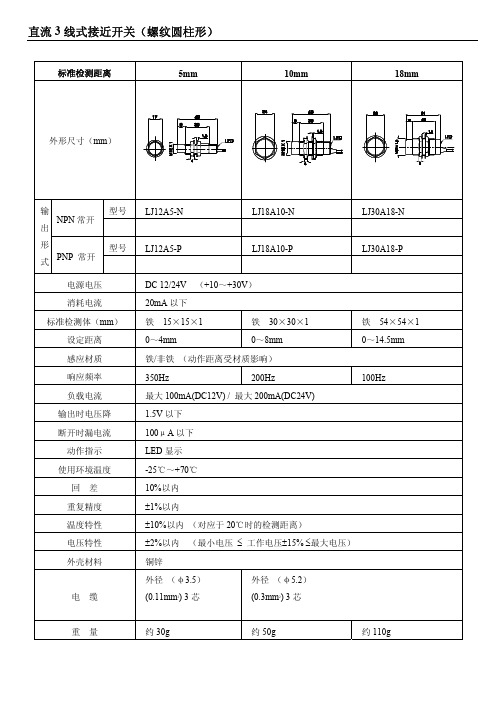
3V 以下
1mA 以下
LED 显示
-25℃~+70℃
20%以内
±1%以内
±10%以内 (对应于 20℃时的检测距离)
±2%以内 (最小电压 ≤ 工作电压±15% ≤最大电压)
铜锌
外径 (φ3.5) (0.11mm2) 3 芯
外径 (φ5.2) (0.3mm2) 3 芯
重量
接近开关使用说明书

接近开关(无接触开关)使用说明书一、集成化接近开关是我厂根据国外技术,引进法国汤姆逊元件制造的新型集成接近开关。
产品品种规格齐全,外型结构多样,电压范围宽,重复精度高,频率响应快,抗干扰性强,使用寿命厂。
开关内腔充以树脂其全封闭,具有耐振动、耐腐蚀、防水、放油等特点。
接近开关型号及含义Proximity switch model and definition二、开关使用注意事项:使用环境温度:使用温度:-25-+70℃;储藏温度:-45-+80℃;湿度:<90%。
1、直流型开关必须用直流稳定压电源,并确保稳压电源波纹Vpp ≤10%,绝缘变压器的次级交流电源经全波整流后,用电解电容滤波(一般为470-1000uF)后的直流电源,最用用直流稳压器供电。
(特别注意:未经电容滤波不能使用)。
2、两线制开关必须先进负载再接至电源,若直接连接电源会使开关损坏。
3、开关不得超过额定技术参数使用。
4、严禁通电接线,严格按接线图上色标接线。
考虑到使用环境的影响,调整开关感应面与检测体之间的距离,一般取额定动作距离Se 的80%。
5、若有高压线和动力线通过接线开关电线附近时,为防止开关受感应误动作或损坏,请用单独金属管屏蔽。
6、直流型开关使用电感性负载时,若系统有较大干扰脉冲时,请在开关断接干扰脉冲抑制器件。
7、两线制开关一般不宜并联或串联使用,建议改用继电器串,并联使用。
8、不同材质的金属检测体对动作距离的影响:9、电容式接近开关动作距离可通过灵敏度微调电位器进行调节(切记在距离最大临界状态下使用)。
10、安求11、霍尔传感器(开关)注意磁钢(引铁石)极性S 极或N 极材料铁(A3) 不锈钢 黄铜 铅 铜 动作距离 100% 50% 40% 30% 30%8、电压输出型NPN.NO/NC。
罗宾康说明书
目录
第一章安全注意事项及产品型号................................................. 4 1.1 安全注意事项........................................................ 4 1.2 变频器型号说明...................................................... 4 1.3 变频器系列型号...................................................... 4 1.4 产品技术指标及规格.................................................. 5
杰尼奥 Pneumatic 按钮和限位开关说明书

0,090 0,090
PXB-B1011BA2 3 PXB-B2011BA2 3
PXB-B1121BA2 3 PXB-B2121BA2 3
PXB-B1011BA3 3 PXB-B2011BA3 3
PXB-B1011BA4 3 PXB-B2011BA4 3
Mushroom head pushbuttons
Latching selector button
45
2 position, Black
45
Latching selector button
45
3 position, Black
45
Latching selector button
45
3 position, Black
45
Non latching selector button Spring
13
with long handle
13
3 position, black
4 2 Non latching selector button
Spring
13
513
with long handle
13
3 position, black
50
0,135 PXB-B1121BD2 3
240
0,135 PXB-B2121BD2 3
Return
Operating force at 6 bar, N
45 45
45 45
Flow
Nl/min
50 240
50 240
Weight Order code
D
Kg
0,100 0,100
0,135 0,135
施耐德电气接近开关产品说明书
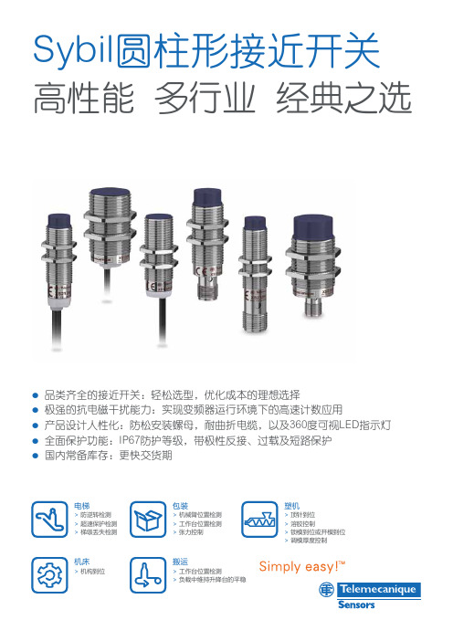
Sybil 圆柱形接近开关高性能 多行业 经典之选p 品类齐全的接近开关:轻松选型,优化成本的理想选择 p 极强的抗电磁干扰能力:实现变频器运行环境下的高速计数应用p 产品设计人性化:防松安装螺母,耐曲折电缆,以及360度可视LED 指示灯p 全面保护功能:IP67防护等级,带极性反接、过载及短路保护p国内常备库存:更快交货期电梯> 防逆转检测> 超速保护检测> 梯级丢失检测机床> 机构到位包装> 机械臂位置检测> 工作台位置检测> 张力控制塑机> 顶针到位> 溶胶控制> 锁模到位或开模到位> 调模厚度控制搬运> 工作台位置检测>负载中维持升降台的平稳施耐德电气(中国)有限公司Schneider Electric (China) Co., 北京市朝阳区望京东路6号施耐德电气大厦邮编: 100102电话: (010) 8434 6699传真: (010) 8450 1130Schneider Electric Building, No. 6, East WangJing Rd., Chaoyang District Beijing 100102 P .R .C.Tel: (010) 8434 6699Fax: (010) 8450 11302017.10SCDOC1412施耐德电气中国版权所有由于标准和材料的变更,文中所述特性和本资料中的图像只有经过我们的业务部门确认以后,才对我们有约束。
本手册采用生态纸印刷客户关爱中心热线:400 810 M8 埋入式1.5 N O PNP 成型电缆(L=2m) 1000 ≤50 XS108BLPAL2C XS108BLPAL2 XS108BLPAL5 M8连接器 1000 ≤50 XS108BLPAM8 M12连接器 1000 ≤50 XS108BLPAM12C XS108BLPAM12 NPN 成型电缆(L=2m) 1000 ≤50 XS108BLNAL2C XS108BLNAL2 M12连接器 1000 ≤50 XS108BLNAM12C XS108BLNAM12 NC PNP M12连接器 1000 ≤50 XS108BLPBM12C NPN 成型电缆(L=2m) 1000 ≤50 XS108BLNBL2C M12连接器 1000 ≤50 XS108BLNBM12C 非埋入式2.5 N O PNP 成型电缆(L=2m) 1000 ≤50 XS208BLPAL2C XS208BLPAL2 成型电缆(L=5m) 1000 ≤50 XS208BLPAL5C XS208BLPAL5 M8连接器 1000 ≤50 XS208BLPAM8 M12连接器 1000 ≤50 XS208BLPAM12 NPN 成型电缆(L=2m) 1000 ≤50 XS208BLNAL2C XS208BLNAL2 M12 埋入式 2 N O PNP 成型电缆(L=2m) 2500 ≤200 XS112BLPAL2 成型电缆(L=3m) 2500 ≤200 XS112BLPAL3 成型电缆(L=5m) 2500 ≤200 XS112BLPAL5 M12连接器 2500 ≤200 XS112BLPAM12 NPN 成型电缆(L=2m) 2500 ≤200 XS112BLNAL2 M12连接器 2500 ≤200 XS112BLNAM12 NC PNP 成型电缆(L=2m) 2500 ≤200 XS112BLPBL2 M12连接器 2500 ≤200 XS112BLPBM12 非埋入式 4 N O PNP 成型电缆(L=2m) 1200 ≤200 XS212BLPAL2 成型电缆(L=3m) 1200 ≤200 XS212BLPAL3 成型电缆(L=5m) 1200 ≤200 XS212BLPAL5 成型电缆(L=10m) 1200 ≤200 XS212BLPAL10 M12连接器 1200 ≤200 XS212BLPAM12C XS212BLPAM12 NPN 成型电缆(L=2m) 1200 ≤200 XS212BLNAL2C XS212BLNAL2 成型电缆(L=7m) 1200 ≤200 XS212BLNAL7 成型电缆(L=10m) 1200 ≤200 XS212BLNAL10C M12连接器 1200 ≤200 XS212BLNAM12 NC PNP 成型电缆(L=2m) 1200 ≤200 XS212BLPBL2 NPN 成型电缆(L=2m) 1200 ≤200 XS212BLNBL2 M18 埋入式5 N O PNP 成型电缆(L=2m) 1200 ≤200 XS118BLPAL2 成型电缆(L=5m) 1200 ≤200 XS118BLPAL5 M12连接器 1200 ≤200 XS118BLPAM12 NPN 成型电缆(L=2m) 1200 ≤200 XS118BLNAL2 成型电缆(L=5m) 1200 ≤200 XS118BLNAL5 M12连接器 1200 ≤200 XS118BLNAM12 NC PNP 成型电缆(L=2m) 1200 ≤200 XS118BLPBL2 M12连接器 1200 ≤200 XS118BLPBM12 NPN 成型电缆(L=2m) 1200 ≤200 XS118BLNBL2 非埋入式8 N O PNP 成型电缆(L=2m) 500 ≤200 XS218BLPAL2 成型电缆(L=5m) 500 ≤200 XS218BLPAL5 成型电缆(L=10m) 500 ≤200 XS218BLPAL10 M12连接器 500 ≤200 XS218BLPAM12C XS218BLPAM12 NPN 成型电缆(L=2m) 500 ≤200 XS218BLNAL2C XS218BLNAL2 成型电缆(L=5m) 500 ≤200 XS218BLNAL5C XS218BLNAL5 成型电缆(L=7m) 500 ≤200 XS218BLNAL7 M12连接器 500 ≤200 XS218BLNAM12 NC PNP 成型电缆(L=2m) 500 ≤200 XS218BLPBL2 NPN 成型电缆(L=2m) 500 ≤200 XS218BLNBL2 M30 埋入式10 N O PNP 成型电缆(L=2m) 500 ≤200 XS130BLPAL2 M12连接器 500 ≤200 XS130BLPAM12 NPN 成型电缆(L=2m) 500 ≤200 XS130BLNAL2 M12连接器 500 ≤200 XS130BLNAM12 NC PNP 成型电缆(L=2m) 500 ≤200 XS130BLPBL2 M12连接器 500 ≤200 XS130BLPBM12 非埋入式15 N O PNP 成型电缆(L=2m) 300 ≤200 XS230BLPAL2 成型电缆(L=5m) 300 ≤200 XS230BLPAL5 M12连接器 300 ≤200 XS230BLPAM12C XS230BLPAM12 NPN 成型电缆(L=2m) 300 ≤200 XS230BLNAL2C XS230BLNAL2 成型电缆(L=5m) 300 ≤200 XS230BLNAL5C 成型电缆(L=7m) 300 ≤200 XS230BLNAL7 成型电缆(L=10m) 300 ≤200 XS230BLNAL10C M12连接器 300 ≤200 XS230BLNAM12 NC PNP 成型电缆(L=2m) 300 ≤200 XS230BLPBL2金属外壳,圆柱型,DC3线 注:M12/M18/M30后缀为C的型号为电梯行业专用型号,更多订制需求,请与当地办事处联系。
艾顿单位电子开关阀系统说明说明书

This Eaton unit is an electrically operated on-off valve used in an aircraft fuel system. The unit consists of two parts, an Actuator, and a Ø1.5” Valve Assembly. The actuator is attached to the valve with two captive bolts and the actuator assembly output shaft engages with the splined drive shaft of the valve. The splined drive shaft is connected to a spherical plug in the valve, which the actuator turns to the selected port position, either OPEN or CLOSED.The Flat Actuator is designed to operate the valve through the required 90 degreesof movement to the open and closed positions. The unit consists of a 28Vdc (nominal) permanent magnet motor and a worm/spur gear arrangement to produce therotational movement.Within the unit travel limitsare controlled by positioncontrol microswitches.Positional indication (OPENor CLOSED) is provided byindependent microswitches.Both of these signalsinterface with the aircraftelectrical system logic. A‘see/feel’ indicator at the endof the output shaft can beseen or felt to also establishthe valve position.Design Features• The valve assembly shownabove (FRH120052K)contains a thermal reliefpill, which can providea pressure relief facility,across the unit to relievesystem pressures thatcan build up. If this facilityis not required then thespherical plug, containingthe thermal relief pill, canbe replaced with a normalplug (FRH120058K).• Ball Valve incorporate anti-icing features to ensurethat any internal pocketslikely to trap water arereduced to a minimum.This ensures that the effecton the operating torqueof the unit, caused bytrapped water subsequentlyfreezing, is reduced.© 2011 Eaton Corporation All Rights Reserved Printed in USAForm No. DS600-127April 2011SpecificationSpecific Operating Characteristics for Combined UnitPart No. .....................FRH120058K & FRH120052K Space Envelope:...............111.2 x 71.7 x 118.5mm . . . . . . . . . . . . . . . . . . . . . . . . . . . . (4.38 x 2.82 x 4.67in)Pressure Range:...............- Operating: 0 - 414kPag . . . . . . . . . . . . . . . . . . . . . . . . . . . . - Proof: 828kPag . . . . . . . . . . . . . . . . . . . . . . . . . . . . - Ultimate: 1160kPagPressure Drop: . . . . . . . . . . . . . . . . 2.5kPa @ 0.5kg/sec.Leakage (External):.............Nil Leakage (Internal): .............0.5cc/min.Temperature Range:............-54 to 110°C (-65 to 230°F)Altitude: .....................-1,000ft to 65,000ft Endurance: ...................40,000 operating cycles MTBF:.......................Approx. 15,000 Op. Hours in. . . . . . . . . . . . . . . . . . . . . . . . . . . . a fighter aircraft application.Dry Weight:...................0.540kg (1.19lbs) maximumT ypical Operating ParametersSpecific Operating Characteristics for ActuatorSpace Envelope:...............118.5 x 34.4 x 71.7mm . . . . . . . . . . . . . . . . . . . . . . . . . . . . 4.67 x 1.35 x 2.82in)Voltage Range:................16 to 32Vdc Current:......................0.6A at rated torque . . . . . . . . . . . . . . . . . . . . . . . . . . . . 1.5A at max. torqueTorque: ......................- Rated (Continuous): 20lbfins . . . . . . . . . . . . . . . . . . . . . . . . . . . . - Stall: 60lbfins @ 31V Rotation Time: ................0.5 to 3 sec over voltage range Rotation Tolerance:.............90º ± 3ºInsulation Resistance: ..........20M W at 500VdcDry Weight:...................0.275kg (0.61lbs) maximumDimensions in mm (in)Eaton Aerospace Limited Aerospace Group Fuel Systems DivisionAbbey Park, Southampton Road Titchfield, Fareham Hampshire, PO14 4QA UKTel: +44 (0)1329 853000Fax: +44 (0)1329 /aerospaceEaton Aerospace Limited Aerospace Group Fuel Systems Division Pathfields Business Park Station Road, South Molton Devon, EX36 3DW UKTel: +44 (0)1769 573371Fax: +44 (0)1769 572755EatonAerospace Group Fuel Systems Division 9650 Jeronimo Road Irvine, California 92618 USATel: (949) 452 9500Fax: (949) 452 9991EatonAerospace Group Fuel Systems Division 23555 Euclid Avenue Cleveland, Ohio 44117 USATel: (216) 692 6000Fax: (216) 692 6331。
接近开关 说明书
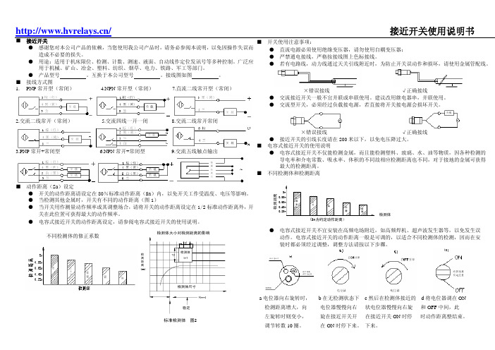
/接近开关使用说明书■ 接近开关● 感谢您对本公司产品的依赖,当您使用我公司产品时,请务必参阅本说明,以免因操作失误而造成不必要的损失。
●用途:适用于机床限位、检测、计数、测速、液面、自动线作定位发讯号等多种控制。
广泛应用于机械、矿山、冶金、塑料、纺织、烟草、电力、铁路、军工等部门。
● 产品型号 。
互换于本公司型号 。
接线图如图 。
■ 接线方式图1.PNP常开型(常闭) 4.NPN常开型(常闭)7.直流二线常开型(常闭)2.交流二线常开(常闭) 5.交流四线一开一闭8.交流二线常开常闭3.PNP常开+常闭型 6.NPN常开+常闭型9.交流五线触点输出■ 动作距离(Sa)设定● 开关的动作距离请设定在80%标准动作距离(Sn)内,以免开关工作受温度、电压等影响。
● 当检测其他金属时,开关有不同的动作距离(图1)● 当开关用作测量动作频率或其调整场合,请将开关的动作距离设定在1/2标准动作距离外,开关在此位置可获得最大的动作频率。
●电容式接近开关的动作距离设定,请参阅电容式接近开关的使用说明。
检测距离(mm)标准检测体 图2检测体大小对检测距离的影响■ 开关使用注意事项:● 直流电源必须使用绝缘变压器,请勿使用自耦变压器:● 严禁通电接线,严格按接线图上色标接线。
● 若有电路线,动力线通过天关引线附近时,为防止开关误动作和损坏,请使用金属管配线。
×错误接线 √正确接线● 交流接近开关一般不宜并联或串联使用。
建议改用继电器串,并联使用。
● 交流型开关,必须经过负载接电源,若直接将开关接电源会损坏开关。
×错误接线√正确接线● 接近开关的引线长度请在200米以下,以免电压降过大。
■ 电容式接近开关的使用说明● 电容式接近开关不仅能检测金属,而且能检测塑料、玻璃、水、油等物质,因各种检测的导电率和介电常数、吸水率、体积的不同故相应检测距离也不同,对于接地的金属可获得最大的检测距离。
■ 不同检测体和检测距离检测距离检测体(Sn为约定动作距离)● 电容式接近开关不宜安装在高频电场附近,如高频焊机、超声波发生器等,以免发生误动作。
E2A-M30LN30-M1-B1接近开关 说明书

——工业安全保护专家E2A-M30LN30-M1-B1接近开关说明书全金属防撞型电感式传感器KJT-WYJ30MQS系列能检测各种金属物体,快速,无触点,寿命极长,动作可靠、性能稳定、频率响应快、使用寿命长、抗干忧能力强、防水、防震、耐腐蚀等特点。
广泛应用于机械、矿山、纺织、印刷、化工、冶金、轻工、阀门、电力、保安、铁路、航天等各个行业更重要的优点是:包括感应面在内的一体化不锈钢外壳。
在KJT-QS系列整个工作期间感应面都绝对不受任何液体,气体(不能腐蚀不锈钢)的侵扰。
感应面处的材料相对较厚,因此耐压性较好。
全金属外壳又使它们比传统传感器更具抗机械力。
因此克服了传统电感式传感器易被撞坏的弱点。
其他属性与传统的传感器一致,达到相关标准,可实现与传统电感式传感器的互换。
E2A-M30LN30-M1-B1型号接近开关类型屏蔽型尺寸M30检测距离10mm±10%——工业安全保护专家精度《2%应差距离检测距离的20%以下检测可能物体磁性金属,非磁性金属会降低检测距离标准检测物体32*32*1t响应频率1000Hz电源电压(使用电压范围)DC12~24V AC90~250V 脉动(p-p)10%以下(DC10~30V)漏电流1mA以下控制输出开关容量3~200mA残留容量 2.5V以下(负载电流100mA、导线长2m时)显示灯动作显示动作状态(检测物体接近时)NO 、NC,NPN,PNP (两线制或者三线制)保护回路负载短路保护、浪涌吸收周围环境温度动作时、保存时:各-25~+75℃(不结冰、不结露)周围环境湿度动作时、保存时:各35~95%RH (不结露)温度的影响-25~+75℃的温度范围内+23℃时、检测距离的±20%以下绝缘电阻50MΩ以下(DC500V兆欧表)充电部整体与外壳间耐电压AC1,000V 50/60Hz 1min 充电部整体与外壳间振动(耐久)10~55Hz 上下振幅1.5mm X、Y、Z各方向 2h 冲击(耐久)1,000m/s2 X、Y、Z各方向10回保护结构不锈钢连接方式导线引出式(标准导线长2m),连接器形式材质外壳不锈钢防松垫片铁亚铅镀层——工业安全保护专家——工业安全保护专家。
接近开关基础知识课件

4.回差值: 动作距离与复位距离之间的绝对值。回差 值越大,对外界的干扰以及被测物的抖动等的抗干扰能力就 越强。
2023/4/21
11
接近开关的检 测距离与回差
2023/4/21
12
接近开关的术语解释(2)
标准检测体:可与现场被检金属作比 较的标准金属检测体。标准检测体通常为 正方形的A3钢,厚度为1mm,所采用的边 长是接近开关检测面直径的2.5倍。
2023/4/21
13
不同材料的金属检测物对电涡流接近开 关动作距离的影响(以Fe为参考金属)
电涡流线圈的阻抗变化与金属导体的电导率、磁
导率等有关。对于非磁性材料,被测体的电导率越高, 则灵敏度越高;被测体是磁性材料时,其磁导率将影 响电涡流线圈的感抗,其磁滞损耗还将影响电涡流线 圈的Q值。磁滞损耗大时,其灵敏度通常较高。
2.为了保证不损坏接近开关,请用户在接通电源前检查接 线是否正确,核定电压是否为额定值。
3.为了使接近开关长期稳定工作,请务必进行定期的维护, 包括被检测物体和接近开关的安装位置是否有移动或松动,接 线和连接部位是否接触不良,是否有金属粉尘粘附等。
4.DC二线制接近开关具有0.5~1mA的静态泄漏电流,在一 些对泄漏电流要求较高的场合下,可改用DC三线制接近开关。
2023/4/21
6
三.接近开关的主要性能指标:
额定动作距离、工作距离、 动作滞差、重复定位精度(重复 性)、动作频率等。
2023/4/21
7
四、电涡流接近开关(电感接近开关)的
工作原理
电涡流式接近开关俗称电感接近开关,属于一种
开关量输出的位置传感器。它由LC高频振荡器和放大
霍尔接近开关使用说明书
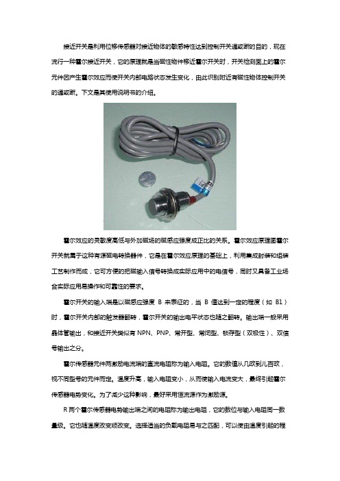
接近开关是利用位移传感器对接近物体的敏感特性达到控制开关通或断的目的,现在流行一种霍尔接近开关,它的原理就是当磁性物件移近霍尔开关时,开关检测面上的霍尔元件因产生霍尔效应而使开关内部电路状态发生变化,由此识别附近有磁性物体控制开关的通或断。
下文是其使用说明书的介绍。
霍尔效应的灵敏度高低与外加磁场的磁感应强度成正比的关系。
霍尔效应原理图霍尔开关就属于这种有源磁电转换器件,它是在霍尔效应原理的基础上,利用集成封装和组装工艺制作而成,它可方便的把磁输入信号转换成实际应用中的电信号,同时又具备工业场合实际应用易操作和可靠性的要求。
霍尔开关的输入端是以磁感应强度B来表征的,当B值达到一定的程度(如B1)时,霍尔开关内部的触发器翻转,霍尔开关的输出电平状态也随之翻转。
输出端一般采用晶体管输出,和接近开关类似有NPN、PNP、常开型、常闭型、锁存型(双极性)、双信号输出之分。
霍尔传感器元件两激励电流端的直流电阻称为输入电阻。
它的数值从几欧到儿百欧,视不同型号的元件而定。
温度升高,输入电阻变小,从而使输入电流变大,最终引起霍尔传感器电势变化。
为了减少这种影响,最好采用恒流源作为激励源。
R两个霍尔传感器电势输出端之间的电阻称为输出电阻,它的数位与输入电阻同一数量级。
它也随温度改变顺改变。
选择适当的负载电阻易与之匹配,可以使由温度引起的程水电势的漂移减至最小。
由于霍尔传感器电势随激励电流的增大而增大,故在应用中总希望选用较大的激励电流1M但激励电流增大,程尔元件的功耗增大,元件的温皮升高,从而引起霍尔传感器屯势的温漂增大,因此每种型号的几件均规定了相应的最大激励电流,它的数值从几毫安至几百毫安。
灵敏度KH=EH/IB,它的数值约为\10MV(MA.T)左右。
(5)最大磁感应强度BM---霍尔传感器参数磁感应强度超过BM时,霍尔传感器电势的非线性误差将明显增大,特斯捡(T)成几千高斯(Gs)(1Gs=104T)。
6M的数值一般为零点刀霍尔传感器输出端之间的开路电压称为不等位电势,使用时多采用电桥法来补偿不等位电势引起日在一定磁感应强度和激励电流的作用下,温度每变化1摄氏度时,霍尔传感器电势变化的百分数弱为霍尔传感器电势温度系数,它与霍尔传感器元件的材料有关。
接近开关手册
传感器礼包完整版资料手册
fae@ - 1 -接近开关手册
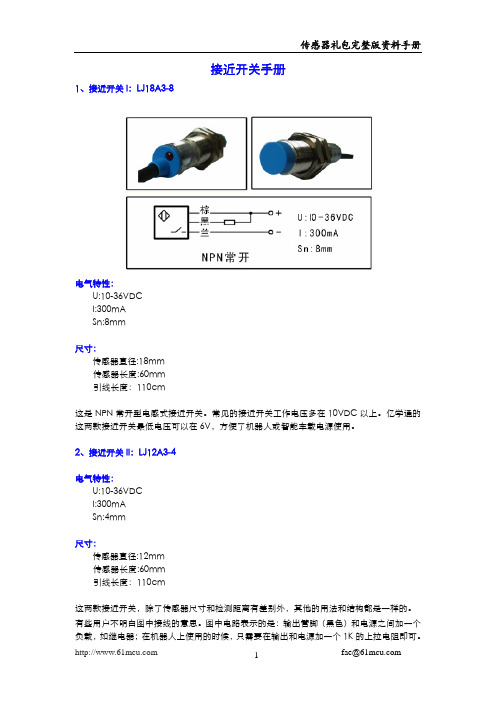
1、接近开关I:LJ18A3-8
电气特性:
U:10-36VDC
I:300mA
Sn:8mm
尺寸:
传感器直径:18mm
传感器长度:60mm
引线长度:110cm
这是NPN 常开型电感式接近开关。
常见的接近开关工作电压多在10VDC 以上。
亿学通的这两款接近开关最低电压可以在6V,方便了机器人或智能车载电源使用。
2、接近开关II:LJ12A3-4
电气特性:
U:10-36VDC
I:300mA
Sn:4mm
尺寸:
传感器直径:12mm
传感器长度:60mm
引线长度:110cm
这两款接近开关,除了传感器尺寸和检测距离有差别外,其他的用法和结构都是一样的。
有些用户不明白图中接线的意思。
图中电路表示的是:输出管脚(黑色)和电源之间加一个负载,如继电器;在机器人上使用的时候,只需要在输出和电源加一个1K 的上拉电阻即可。
艾乐格A1201霍尔效应双极开关说明书

DescriptionThe Allegro ® A1201 Hall-effect bipolar switch is a next-generation replacement and extension of the popular Allegro A3134 bipolar switch. Overall, the A1201, produced with BiCMOS technology, is a continuous-time device that features fast power-on time and low-noise operation. Device programming is performed after packaging, to ensure increased switchpoint accuracy by eliminating offsets that can be induced by package stress. Unique Hall element geometries and low-offset amplifiers help to minimize noise and to reduce the residual offset voltage normally caused by device overmolding, temperature excursions, and thermal stress.The A 1201 Hall-effect bipolar switch includes the following on a single silicon chip: voltage regulator, Hall-voltage generator, small-signal amplifier, Schmitt trigger, and NMOS output transistor. The integrated voltage regulator permits operation from 3.8 to 24 V . The extensive on-board protection circuitry makes possible a ±30 V absolute maximum voltage rating for superior protection in automotive and motor commutation applications, without adding external components. The device is a member of the A1201 product family which has identical electrical characteristics throughout, but provides a range of magnetic switchpoints.Features and Benefits▪ Continuous-time operation ▫ Fast power-on time ▫ Low noise▪ Stable operation over full operating temperature range ▪ Reverse battery protection ▪ Solid-state reliability▪ Factory-programmed at end-of-line for optimum performance▪ Robust EMC performance ▪ High ESD rating▪ Regulator stability without a bypass capacitorContinuous-Time Bipolar SwitchContinued on the next page…Packages: 3 pin SOT23W (suffix LH), and3 pin SIP (suffix UA)Functional Block DiagramNot to scaleA1201VOUTThe small geometries of the BiCMOS process allow these devices to be provided in ultrasmall packages. The package styles available provide magnetically optimized solutions for most applications. Package LH is a SOT23W, a miniature low-profile surface-mountpackage, while package UA is a three-lead ultramini SIP for through-hole mounting. Each package is lead (Pb) free, with 100% matte tin plated leadframes.Selection GuidePart NumberPacking 1MountingAmbient, T AB RP (Min)B OP (Max)A 1201ELHLT-T 2 7-in. reel, 3000 pieces/reel 3-pin SOT23W surface mount–40ºC to 85ºC–5050A1201EUA-T 2Bulk, 500 pieces/bag 3-pin SIP through hole A1201LLHLT-T 27-in. reel, 3000 pieces/reel 3-pin SOT23W surface mount–40ºC to 150ºCA1201LUA-T 2Bulk, 500 pieces/bag3-pin SIP through hole1Contact Allegro for additional packing options.2Variant is obsolete.Description (continued)Absolute Maximum RatingsCharacteristicSymbol Notes Rating Units Supply Voltage V CC 30V Reverse Supply Voltage V RCC –30V Output Off Voltage V OUT 30V Reverse Output Voltage V ROUT –0.5V Output Current Sink I OUTSINK25mA Magnetic Flux DensityBUnlimitedG Operating Ambient Temperature T A Range E –40 to 85ºC Range L–40 to 150ºC Maximum Junction Temperature T J (max)165ºC Storage TemperatureT stg–65 to 170ºCPin-out DiagramsTerminal ListName DescriptionNumberPackage LH Package UAVCC Connects power supply to chip 11VOUT Output from circuit 23GNDGround32G N DV O U TV C CPackage UAPackage LHN DV O U V COPERATING CHARACTERISTICS over full operating voltage and ambient temperature ranges, unless otherwise noted Characteristic Symbol Test Conditions Min.Typ.Max.Units Electrical CharacteristicsSupply Voltage1V CC Operating, T J < 165°C 3.8–24V Output Leakage Current I OUTOFF V OUT = 24 V, B < B RP––10μA Output On Voltage V OUT(SAT)I OUT = 20 mA, B > B OP–215400mVPower-On Time2t PO Slew rate (dV CC/dt) < 2.5 V/μs, B > B OP(max) + 5 Gor B < B RP(min) – 5 G––4μsOutput Rise Time3t r V CC = 12 V, R LOAD = 820 Ω, C S = 12 pF––2μs Output Fall Time3t f V CC = 12 V, R LOAD = 820 Ω, C S = 12 pF––2μsSupply Current I CCON B > B OP– 3.87.5mA I CCOFF B < B RP– 3.57.5mAReverse Battery Current I RCC V RCC = –30 V–––10mA Supply Zener Clamp Voltage V Z I CC = 30 mA; T A = 25°C32––V Supply Zener Current4I Z V Z = 32 V; T A = 25°C––30mA Magnetic Characteristics5Operate Point B OP A1201South pole adjacent to branded faceof device–401550GRelease Point B RP A1201North pole adjacent to branded faceof device–50–1540GHysteresis B HYS A1201B OP – B RP53055G1 Maximum voltage must be adjusted for power dissipation and junction temperature, see Power Derating section.2 For V CC slew rates greater than 250 V/μs, and T A = 150°C, the Power-On Time can reach its maximum value.3 C S =oscilloscope probe capacitance.4 Maximum current limit is equal to the maximum I CC(max) + 22 mA.5 Magnetic flux density, B, is indicated as a negative value for north-polarity magnetic fields, and as a positive value for south-polarity magnetic fields. This so-called algebraic convention supports arithmetic comparison of north and south polarity values, where the relative strength of the field is indicated by the absolute value of B, and the sign indicates the polarity of the field (for example, a –100 G field and a 100 G field have equivalent strength, but opposite polarity).DEVICE QUALIFICATION PROGRAMContact Allegro for information.EMC (Electromagnetic Compatibility) REQUIREMENTSContact Allegro for information.THERMAL CHARACTERISTICS may require derating at maximum conditions, see application informationCharacteristicSymbolTest ConditionsValue Units Package Thermal ResistanceR θJAPackage LH, 1-layer PCB with copper limited to solder pads228ºC/W Package LH, 2-layer PCB with 0.463 in.2 of copper area each side connected by thermal vias110ºC/W Package UA, 1-layer PCB with copper limited to solder pads165ºC/W6789234510111213141516171819202122232425M a x i m u m A l l o w a b l e V C C (V )T = 165ºC; I = I Power Derating Curve V CC(min)V CC(max)100200300400500600700800900100011001200130014001500160017001800190020406080100120140160180Temperature (°C)P o w e r D i s s i p a t i o n , P D (m W )Power Dissipation versus Ambient TemperatureCharacteristic DataFunctional DescriptionBipolar Device SwitchingThe A1201 provides highly sensitive switching for applica-tions using magnetic fields of alternating polarities, such as ring magnets. There are three switching modes for bipolar devices, referred to as latch , unipolar switch , and negative switch . Mode is determined by the switchpoint characteristics of the individual device. The characteristic hysteresis, B HYS , of the device, is the difference in the relative magnetic strength and polarity of the switchpoints of the device. (Note that, in the following descrip-tions, a negative magnetic value indicates a north polarity field, and a positive magnetic value indicates a south polarity field. For a given value of magnetic strength, B X , the values –B X and B X indicate two fields of equal strength, but opposite polarity. B = 0 indicates the absence of a magnetic field.)Bipolar devices typically behave as latches. In this mode, magnetic fields of opposite polarity and equivalent strengths are needed to switch the output. When the magnetic fields are removed (B 0) the device remains in the same state until a magnetic field of the opposite polarity and of sufficient strength causes it to switch. The hysteresis of latch mode behavior is shown in panel A of figure 1.In contrast to latching, when a device exhibits unipolar switch-ing, it only responds to a south magnetic field. The field must be of sufficient strength, > B OP , for the device to operate. When the field is reduced beyond the B RP level, the device switches back to the high state, as shown in panel B of figure 1. Devices exhibiting negative switch behavior operate in a similar but opposite manner. A north polarity field of sufficient strength, > B RP , (more north than B RP ) is required for operation, although the result is that V OUT switches high, as shown in panel C. WhenFigure 1. Bipolar Device Output Switching Modes. These behaviors can be exhibited when using a circuit such as that shown in panel D. Panel A displays the hysteresis when a device exhibits latch mode (note that the B HYS band incorporates B= 0), panel B shows unipolar switch behavior (the B HYS band is more positive than B = 0), and panel C shows negative switch behavior (the B HYS band is more negative than B = 0). Bipolar devices, such as the A1201, can operate in any of the three modes.HYS V O U THYS HYSV OUT(SAT)CC(A)(B)(C)(D)the field is reduced beyond the B OP level, the device switches back to the low state.The typical output behavior of the A1201 device is latching. That is, switching to the low state when the magnetic field at the Hall element exceeds the operate point threshold, B OP . At this point, the output voltage is V OUT(SAT). When the magnetic field is reduced to below the release point threshold, B RP , the device output, V OUT , goes high. The values of the magnetic parameters are specified in the Magnetic Characteristics table, on page 3. Note that, as shown in figure 1, these switchpoints can lie in either north or south polarity ranges.The A1201 is designed to attain a small hysteresis, and thereby provide more sensitive switching. Although this means that true latching behavior cannot be guaranteed in all cases, proper switching can be ensured by use of both south and north mag-netic fields, as in a ring magnet. The hysteresis of the A1201 allows clean switching of the output, even in the presence of external mechanical vibration and electrical noise.Bipolar devices adopt an indeterminate output state when pow-ered-on in the absence of a magnetic field or in a field that lies within the hysteresis band of the device.For more information on Bipolar switches, refer to Application Note 27705, Understanding Bipolar Hall Effect Sensor ICs .CONTINUOUS-TIME BENEFITSContinuous-time devices, such as the A1201, offer the fastest available power-on settling time and frequency response. Due to offsets generated during the IC packaging process, continuous-time devices typically require programming after packaging to tighten magnetic parameter distributions. In contrast, chopper-stabilized switches employ an offset cancellation technique on the chip that eliminates these offsets without the need for after-packaging programming. The tradeoff is a longer settling time and reduced frequency response as a result of the chopper-stabilization offset cancellation algorithm.Figure 2. Continuous-Time Application, B < B RP .. This figure illustrates the use of a quick cycle for chopping V CC in order to conserve battery power. Position 1, power is applied to the device. Position 2, the output assumes the correct state at a time prior to the maximum Power-On Time, t PO(max). The case shown is where the correct output state is HIGH . Position 3, t PO(max) has elapsed. The device output is valid. Position 4, after the output is valid, a control unit reads the output. Position 5, power is removed from the device.VV PO(max)The choice between continuous-time and chopper-stabilized designs is solely determined by the application. Battery manage-ment is an example where continuous-time is often required. In these applications, V CC is chopped with a very small duty cycle in order to conserve power (refer to figure 4). The duty cycleis controlled by the power-on time, t PO, of the device. Because continuous-time devices have the shorter power-on time, they are the clear choice for such applications.For more information on the chopper stabilization technique, refer to Technical Paper STP 97-10, Monolithic Magnetic Hall Sensing Using Dynamic Quadrature Offset Cancellation and Technical Paper STP 99-1, Chopper-Stabilized Amplifiers with a Track-and-Hold Signal Demodulator.ADDITIONAL APPLICATIONS INFORMATION Extensive applications information for Hall-effect devices is available in:• Hall-Effect IC Applications Guide, Application Note 27701• Hall-Effect Devices: Gluing, Potting, Encapsulating, Lead Welding and Lead Forming, Application Note 27703.1• Soldering Methods for Allegro’s Products – SMT and Through-Hole, Application Note 26009All are provided in Allegro Electronic Data Book, AMS-702, and the Allegro Web site, .Power Derating Power DeratingThe device must be operated below the maximum junction temperature of the device, T J(max). Under certain combinations of peak conditions, reliable operation may require derating sup-plied power or improving the heat dissipation properties of the application. This section presents a procedure for correlating factors affecting operating T J. (Thermal data is also available on the Allegro MicroSystems Web site.)The Package Thermal Resistance, RθJA, is a figure of merit sum-marizing the ability of the application and the device to dissipate heat from the junction (die), through all paths to the ambient air. Its primary component is the Effective Thermal Conductivity, K, of the printed circuit board, including adjacent devices and traces. Radiation from the die through the device case, RθJC, is relatively small component of RθJA. Ambient air temperature,T A, and air motion are significant external factors, damped by overmolding.The effect of varying power levels (Power Dissipation, P D), can be estimated. The following formulas represent the fundamental relationships used to estimate T J, at P D.P D = V IN× I IN (1)∆T = P D× RθJA(2)T J = T A + ΔT (3)For example, given common conditions such as: T A= 25°C,V CC = 12 V, I CC = 4 mA, and RθJA = 140 °C/W, then:P D = V CC× I CC = 12 V × 4 mA = 48 mW∆T = P D× RθJA = 48 mW × 140 °C/W = 7°CT J = T A + ∆T = 25°C + 7°C = 32°CA worst-case estimate, P D(max), represents the maximum allow-able power level (V CC(max), I CC(max)), without exceeding T J(max), at a selected RθJA and T A.Example: Reliability for V CC at T A =150°C, package UA, using minimum-K PCB.Observe the worst-case ratings for the device, specifically:RθJA =165°C/W, T J(max) =165°C, V CC(max) =24 V, andI CC(max) =7.5mA.Calculate the maximum allowable power level, P D(max). First, invert equation 3:∆T max = T J(max) – T A = 165°C–150°C = 15°CThis provides the allowable increase to T J resulting from internal power dissipation. Then, invert equation 2:P D(max) = ∆T max ÷ RθJA = 15°C ÷ 165 °C/W = 91 mWFinally, invert equation 1 with respect to voltage:V CC(est) = P D(max) ÷ I CC(max) =91 mW ÷ 7.5 mA = 12.1 VThe result indicates that, at T A, the application and device can dissipate adequate amounts of heat at voltages ≤V CC(est). Compare V CC(est) to V CC(max). If V CC(est)≤ V CC(max), then reli-able operation between V CC(est) and V CC(max) requires enhanced RθJA. If V CC(est)≥ V CC(max), then operation between V CC(est) and V CC(max) is reliable under these conditions.Package LH, 3-Pin (SOT-23W)A Active Area Depth, 0.28 mm REFB C Reference land pattern layoutAll pads a minimum of 0.20 mm from all adjacent pads; adjust as necessaryto meet application process requirements and PCB layout tolerancesBranding scale and appearance at supplier discretionN = Last two digits of device part numberT = Temperature code2.90+0.12For Reference Only; not for tooling use (reference dwg. 802840)Dimensions in millimetersDimensions exclusive of mold flash, gate burrs, and dambar protrusionsExact case and lead configuration at supplier discretion within limits shownD Hall element, not to scalePackage UA, 3-Pin SIPCopyright ©2005-2009, Allegro MicroSystems, Inc.Allegro MicroSystems, Inc. reserves the right to make, from time to time, such de p ar t ures from the detail spec i f i c a t ions as may be required to permit improvements in the per f or m ance, reliability, or manufacturability of its products. Before plac-ing an order, the user is cautioned to verify that the information being relied upon is current.Allegro’s products are not to be used in life support devices or systems, if a failure of an Allegro product can reasonably be expected to cause the failure of that life support device or system, or to affect the safety or effectiveness of that device or system.The in f or m a t ion in c lud e d herein is believed to be ac c u r ate and reliable. How e v e r, Allegro MicroSystems, Inc. assumes no re s pon s i b il i t y for its use; nor for any in f ringe m ent of patents or other rights of third parties which may result from its use.For the latest version of this document, visit our website:EEGate burr areaA B C Dambar removal protrusion (6X)D ED Branding scale and appearance at supplier discretion Hall element, not to scaleActive Area Depth, 0.50 mm REF For Reference Only; not for tooling use (reference DWG-9049)Dimensions in millimetersDimensions exclusive of mold flash, gate burrs, and dambar protrusions Exact case and lead configuration at supplier discretion within limits shownStandard Branding Reference View = Supplier emblemN = Last two digits of device part number T = Temperature codeFace+0.083.02。
爱立智电子(Eaton)的照明接触器说明书

Lighting contactorsEaton’s lighting contactors are specifically designed for lighting loads and are ratedspecifically for the high inrush currents associated with lighting loads. These lighting contactors, available as mechanically or electrically held, are an ideal solution for controlling tungsten (incandescent filament), ballast (fluorescent and mercury arc), high intensity discharge (HID) and non-motor AC resistive loads.Sample applications• Hospitals • Office buildings • Industrial plants • Airports •Stadiums•Designed for large loads, 30-400A, 2-12 poles (12 poles up to 200A)•Mechanically held•Designed with a permanent magnet that will maintain the contactor in its energized state indefinitely without using control power•Magnetically latched•Enables the contactor to operate with no coil hum•No control power necessary to maintain contact closure•Ideal for applications where contact closure is required during power failure•Modular design with up to 12 power poles (30A per pole max.) flexibility to add/remove poles•Easy to snap on additional poles• Low magnet noise•Power poles convert from NO to NC with a simple 180 degree turn •Electrically or mechanically held•Field convertible from electrically held t o mechanically held and nice versa•Ideal for 20-30A applications that require quiet and energy-efficient operation.•Full line of Freedom snap-on accessories:•Pneumatic timers, solid-state timers, suppressors and auxiliaries (side and top mounted)• Electrically held• Standard with 1NO auxiliary contact •Ideal for applications where it is not critical that contacts stay closed with loss of control power.•Needs continuous control power for operationA202C30CNCN35Ratings:• 30A – 400A, 12 Poles•30A – 200A (2P-12P)•300A & 400A (2P &3PRatings:• 30A only•2P – 12PRatings:• 10A – 400A, 12 Poles• 10A (2P-4P)•20A – 30A (2P-12P)• 60A (2P-5P)•100A – 400A (2P&3P)Features• Easy to install and maintain • Industrial and efficient •Safe and convenient means for local or remote switching of lamp loads•Suitable for pressure and high-pressure sodium lamp loads and other non-motor (resistive) loads•Can withstand the large initial inrush currents of tungsten lamp loads without contact welding •AC and DC coil voltages available • Wide range of available accessories for each contactor type•Fully rated and does not require de-rating •Open and enclosed options availableRelated materials and documentation•Catalog CA08100006E – Volume 5, Tab 6: Lighting •Lighting Contactors Quick Selector - TD03701001E •C30CN Lighting Brochure - PA037001EN • /a202• /c30cn •/cn35Eaton1000 Eaton Boulevard Cleveland, OH 44122United States © 2021 EatonAll Rights Reserved Printed in USAPublication No. PA037012EN / NFMD March 2021Eaton is a registered trademark.All other trademarks are property of their respective owners.For more information, visit/lightingcontactorsA202 Catalog selectionContinuous amps Number Open typeA202 Magnet coil selectionA Available on two- to five-pole, 30 and 60A devices andon two- to three-pole 100 and 200A devices.CN35 Catalog selectionMax ampere Number Open TypeCN35 Magnet coil selection 1 For 10, 20 and 30A sizes only. Sizes 60–400A are 24V/60 Hz only.2 For 10, 20 and 30A sizes only.Simple catalog number Digit position: C 2 0 C N M 2 2 A A 2 A 01 2 3 4 5 6 7 8 9 10 11 12 13C30CN Catalog selection – from catalog page V5-T6-5Follow us on social media to get the latest product and support information.。
接近开关说明书
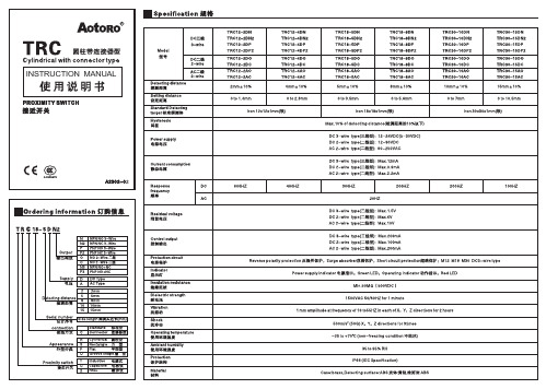
Vs:power supply 电源P:Bleeder resister,number of W 分流电阻功率Io:Min.operating current of proximity switch接近开关的最小动作电流Ioff:Return current of load 负载的恢复电流110VAC 50/60HZ,bleeder resister over 20K,Min.3W220VAC 50/60HZ,bleeder resister over 39K,Min.5WBe sure to follow the safety precautions below for adder safety以下项目在安全确保方面非常重要,请务必遵守。
.1.Do not use the sensor under the explosive or flammable gas environment.请不要在具有可燃性、爆炸性气体的环境下使用。
2.Never disassemble, repair or tamper the product.请勿拆卸、修理、改造本产品。
3.Keep the supply voltage within the specified area.电源电压必须在额定值内。
e the load under the specified area.请使用额定值以下的负荷。
Caution for using正确使用方法1.Do not use the product under the following conditions.请不要在以下的环境中使用。
(1)In the place of the direct sunlight.日光直射场所。
(2)In the place where humidity is high and condensation may occur.湿度高或易结露场所。
(3)In the place of the corrosive gas exists.含腐蚀性气体场所。
电子开关商品说明书

N A V I G A T I S W I T C H E R O C K E R S W I T C H E S R O T A R Y S W I T C H E S S L I D E S W I T C H E S S N A P A C T I O NS W I T C H E ST A C T I L E S W I T C H E ST O G G L E S W I T C H E S C A P O P T I O N SP U S H B U T T O N S W I T C H E SAudio / Visual Security Devices Industrial ControlsElectrical Housewares Kiosks SpecificationsPart Number ConfiguratorFeatures & BenefitsApplications / Markets• 16mm diameter panel cutout• Single, Bi-color, and RGB LED options • Dot or ring illumination options available• Illuminated ring with laser etched power symbol graphic option• Illuminated ring and power symbol graphic option • Multiple actuator options • Pilot indicator option• IP65 rated, Off-(On), SPST•Soldered wire leads (300mm long) optionalElectrical Rating: 2A, 48VDCMechanical Life: 1,000,000 Cycles Electrical Life: 50,000 CyclesContact Resistance: 50mΩ Max. Insulation Resistance: 1000 MΩ Min. Dielectric Strength: 2,000VACOperating/Storage Temperature: -20°C to 55°C Travel: 1.80mm (Non-Illuminated) 2.20mm (Illuminated) Moisture Protection: IP65Contact Arrangement: SPST Off-(On)Actuation Force: 400 gf Panel Thickness: 1-10mmMounting Nut Torque: 5-14NmF - Flat H - HighActuator Options Medical Equipment2 - Solder W - Wire Terminal Options 4 - Off - (On)*Function OptionsANTI-VANDAL SWITCHES DETECTOR SWITCHES DIP SWITCHESKEYLOCK SWITCHESNAVIGATION SWITCHES ROCKER SWITCHESROTARY SWITCHESSLIDE SWITCHESSNAP ACTION SWITCHESTACTILE SWITCHESTOGGLE SWITCHESCAP OPTIONSPUSHBUTTON SWITCHES ANTI-VANDAL SWITCHESBody DimensionsLED IlluminationBody Dimensions RGB Illumination+12+2-1.50[.059 in]16.50[.650 in]20.0[.787 in]M16 x 1.0THREAD8.50[.335 in].84[.033 in]1.88[.074 in]SHOWN WITH OPTIONAL DOT ILLMINATION9.40[.370 in] 11.80[ .465 in]SHOWN WITH OPTIONALRING ILLUMINATION18.00[.709 in]7.00[.276 in] 3.50[.138 in]2.00[.079 in]20.00[.787 in]16.50[.650 in]1.50[.059 in]M16 x 1.0THREAD9.80[.386 in]3.00[.118 in]ANODE RED LED ANODE GREEN LED ANODE BLUE LEDLED CATHODE ALL 3 COLORS18.00[ .709 in]A N T I -V A N D A L S W I T C H E SD E T E C T O R S W I T C H E SD I P S W I T C HE S K E Y L O C K S W I T C H E SN A V I G A T I O N S W I T C H E S R O C K E R S W I T C H E S R O T A R Y S W I T C H E SS L I D E S W I T C H E SS N A P A C T I O N S W I T C H E S T A C T I L E S W I T C H E S T O G G L E S W I T C H E SC A P O P T I O N SP U S H B U T T O N S W I T C H E SS W I T C H E S Body Dimensions Standard LED Wire Lead** WIRE LEADS PROVIDED ARE DEPENDANT ON THE FUNCTION AND/OR ILLUMINATION SELECTED **WITH GRAPHIC WITHOUT GRAPHIC(4) WIRE, 22 AWG,AWM UL1007 WITH ENDS PRE-STRIPPEDM16x1.0HEATSHRINK OVER SOLDERED CONNECTIONSCABLE TIE25.4[1.0 in]()13.0 2.0.5 .1 in []1.50[.06 in]16.5[.65 in]300.0 10.011.8 .4 in [](+)(-)12SWITCH WIRELENGTH SW1-1WIRE, 22AWG AWM UL1007, WHITE 300.0 [11.8 in]SW1-2WIRE, 22AWG AWM UL1007, GREEN 300.0 [11.8 in]SW1- (+)WIRE, 22AWG AWM UL1007, RED 300.0 [11.8 in]SW1- (-)WIRE, 22AWG AWM UL1007, BLACK300.0 [11.8 in]16.00 -.00.20+.630-.000.008+ in[ ]16.00 -.00.20+.630-.000.008+ in[ ]15.40-.00.10+.606-.000.004+in[]PANEL THICKNESS1-10mm'sRecommended Panel CutoutsANTI-VANDAL SWITCHES DETECTOR SWITCHES DIP SWITCHES KEYLOCK SWITCHESNAVIGATION SWITCHES ROCKER SWITCHESROTARY SWITCHESSLIDE SWITCHES SNAP ACTION SWITCHESTACTILE SWITCHESTOGGLE SWITCHESCAP OPTIONSPUSHBUTTON SWITCHESANTI-VANDAL SWITCHESRecommended Panel CutoutsBody DimensionsStandard RGB Wire LeadBOTTOM VIEWSHOWN WITHOUTWIRING** WIRE LEADS PROVIDED ARE DEPENDANT ON THE FUNCTION AND/OR ILLUMINATION SELECTED **WITH GRAPHIC WITHOUT GRAPHIC(4) WIRE, 22 AWG,AWM UL1007 WITH ENDS PRE-STRIPPEDHEATSHRINK OVER SOLDERED CONNECTIONSM16 X 1.0CABLE TIE13.0 2.0.5 .1 in []1.50[.06 in]25.4[1.0 in]()16.5[.65 in]300.0 10.011.8 .4 in []LEDCATHODE (-)RED LED ANODE (+)BLUE LED ANODE (+)GREEN LED ANODE (+)12SWITCH WIRESW1-1WIRE, 22AWG STRANDED AWM UL1007, WHITE SW1-2WIRE, 22AWG STRANDED AWM UL1007, YELLOW SW1-RED (+)WIRE, 22AWG STRANDED AWM UL1007, RED SW1-GREEN (+)WIRE, 22AWG STRANDED AWM UL1007, GREEN SW1-BLUE (+)WIRE, 22AWG STRANDED AWM UL1007, BLUE SW1- (-)WIRE, 22AWG STRANDED AWM UL1007, BLACK16.00-.00.20+.630-.000.008+ in[]16.00 .20.630 .008 in [ ]15.40-.00.10+.606-.000.004+ in[]PANEL THICKNESS1-10mm'sANTI-VANDAL SWITCHES DETECTOR SWITCHESDIP SWITCHESKEYLOCK SWITCHESNAVIGATION SWITCHESROCKER SWITCHESROTARY SWITCHESSLIDE SWITCHESSNAP ACTION SWITCHESTACTILE SWITCHESTOGGLE SWITCHESCAP OPTIONSPUSHBUTTON SWITCHES ANTI-VANDAL SWITCHESPV6 Series Anti-vandal SwitchRecommended Panel CutoutsHigh ActuatorFlat Actuator Actuator OptionsGraphic OptionsSchematics and Panel CutoutsWITH GRAPHIC WITHOUT GRAPHIC12NON-ILUMINATEDSTANDARD ILLUMINATED+-R G BRGBILLUMINATED-1122 11.90[.469 in]ACTUATOR FLUSH TO TOP OF BEZEL1.50[.059 in]2.90[.114 in]11.90[.469 in]PANEL THICKNESS1-10 mm's16.00 -.00.20+.630-.000.008+ in[ ]LASER ETCHEDILLUMINATEDORIENTATION FLAT FOR GRAPHICILLUMINATEDORIENTATION FLAT FOR GRAPHIC16.00 -.00.20+.630-.000.008+ in[ ]15.40-.00.10+.606-.000.004+ in[]M01 - Illuminated Ring LaserEtched Power Symbol M15 - Illuminated Ring andPower Symbol。
无线接近开关-无线光电开关使用说明

Network Devices
GATEWAY
NODE
NODE
NODE
NODE
0 1 23 4
NODE
NODE
NODE
56 7
NODE
NODE
NODE
NODE
NODE
NODE
NODE
NODE
8 9 10 11 12 13 14 15
在不同的频道间跳变,抗干扰能力更强。好似一 条道路划分成若干车道,不堵车
6
Tx Rx
Send and receive interval for Node 2
time
TDMA frame for a network of 8 Nodes
TDMA frame for a network of 15 nodes
信号强度 信号强度
Frequency Hopping Spread Spectrum
日前针对接近(光电)等传感器能够远距离稳定传 输,自主研发了新产品KJT-WLTC无线传感器。采用最新的
无线技术,最远感 应距离能达到1000 米,使用简单方便, 极大节约了测试中 由于反复布设有线 数据设备而消耗的 人和物力,能够克 服恶劣的工作环境, 广泛应用流于量数监据视 采 集和工业设备在线 监测。
0 OUT 1
0 OUT 2 D normal OUT 3 normal OUT 4
GATEWAY
Link Status
OK
D OUT 1
0
NODE 1
OUT 2 0
Link between Gateway and Node 1 timed out.
D OUT 1 normal
NODE 2
微波感应开关使用说明书 适用于微波感应灯 人体感应灯 雷达感应开关 智能感应灯

微波感应开关:LQ-K05 LQ-K09 LQ-K11 LQ-K15 微波感应灯:LQ-L201 LQ-L215 LQ-L221 LQ-L207 LQ-L213 LQ-L238 LQ-L237 LQ-L235 LQ-L223 LQ-L210
雷达感应开关,又称微波感应开关,是根据多普勒效应为基础,采用最先进的平面天线,可有效抑制高次谐波和其他杂波的 干扰﹑灵敏度高﹑可靠性强﹑安全方便﹑智能节能, 是楼宇智能化和物业管理现代化的首选产品。 微功耗﹑功能齐全﹑可以 带各类灯具。 可穿透部分非金属物感应,特别适用于隐藏安装在灯具内部
查看绿庆产品:
lql201lql215lql221lql207lql213lql238lql237lql235lql223lql210雷达感应开关又称微波感应开关是根据多普勒效应为基础采用最先进的平面天线可有效抑制高次谐波和其他杂波的干扰灵敏度高可靠性强安全方便智能节能是楼宇智能化和物业管理现代化的首选产品
微波感应灯 微波感应开关系列使用说明书
