3080使用说明书
上海庆科EMC3080 Wi-Fi BLE物联网模组说明书
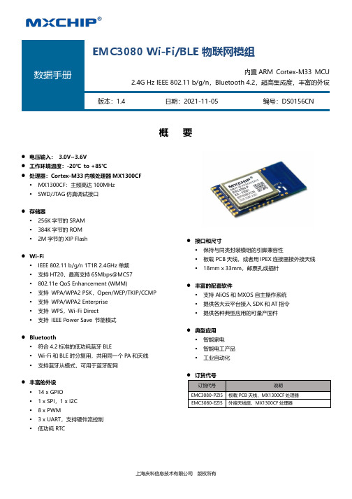
概 要⚫ 电压输入: 3.0V~3.6V ⚫ 工作环境温度:-20℃ to +85℃⚫ 处理器:Cortex-M33内核处理器MX1300CF▪ MX1300CF :主频高达100MHz ▪ SWD/JTAG 仿真调试接口 ⚫ 存储器▪ 256K 字节的SRAM ▪ 384K 字节的ROM ▪ 2M 字节的XIP Flash ⚫ Wi-Fi▪ IEEE 802.11 b/g/n 1T1R 2.4GHz 单频 ▪ 支持HT20,最高支持65Mbps@MCS7 ▪ 802.11e QoS Enhancement (WMM)▪ 支持 WPA/WPA2 PSK ,Open/WEP/TKIP/CCMP ▪ 支持 WPA/WPA2 Enterprise ▪ 支持 WPS ,Wi-Fi Direct ▪ 支持 IEEE Power Save 节能模式⚫ Bluetooth▪ 符合4.2标准的低功耗蓝牙BLE▪ Wi-Fi 和BLE 时分复用,共用同一个PA 和天线 ▪ 支持蓝牙从模式,可用于蓝牙配网⚫ 丰富的外设▪ 14 x GPIO ▪ 1 x SPI ,1 x I2C ▪ 8 x PWM▪ 3 x UART ,支持硬件流控制 ▪ 低功耗RTC⚫ 接口和尺寸▪ 保持与同类封装模组的引脚兼容性▪ 板载PCB 天线,或者用IPEX 连接器接外接天线 ▪ 18mm x 33mm ,邮票孔或插针 ⚫ 丰富的配套软件▪ 支持AliOS 和MXOS 自主操作系统 ▪ 提供各大云平台接入SDK 和AT 指令 ▪ 提供各种典型应用的可量产固件⚫ 典型应用▪ 智能家电 ▪ 智能电工产品 ▪ 工业自动化EMC3080 Wi-Fi/BLE 物联网模组内置ARM Cortex-M33 MCU2.4G Hz IEEE 802.11 b/g/n ,Bluetooth 4.2,超高集成度,丰富的外设版本:1.4日期:2021-11-05编号:DS0156CN系列订货代码08 -P Z I 5 -xxx如需了解所有相关特性清单(如包装,最小订单量等)和其他方面的信息,请联系就近MXCHIP销售点和代理商。
Z3080电气、液压控制说明

中捷Z3080X25 摇臂钻床电气控制说明本文件适用于Z3080X25型摇臂钻床。
本机床执行标准:GB/T4017-1997《摇臂钻床精度检验》标准。
请妥善保存本手册以为日后操作维修之用安全警示◆机床在吊运时及与地基固定之前,切勿松开立柱的夹紧,否则造成机床的倾倒。
◆机床安装后,请将导轨、外立柱等表面的防锈油擦洗干净,并涂30号机油,否则易研伤导轨等表面。
◆试车前务必将夹紧摇臂的菱形块上的放松板拆下,否则摇臂不能松开。
◆接通电源时,请检查电源相序是否正确,否则机床不能正常开动。
◆请按机床上润滑标牌的规定,对机床各部位注油润滑,否则研伤导轨或机件。
◆机床使用过程中摇臂沿着一个方向连续转动不得超过360°,否则将内立柱的电源线拧断造成短路,危及人身安全。
◆主轴自动进给时,主轴移动手柄转动,请操纵者注意远离手柄,否则易碰伤。
◆钻削前切记将摇臂、立柱及主轴箱夹紧,否则易造成人身事故。
◆钻削过程中绝对不可用手清除铁屑和触摸钻头,观察钻削情况时头部与钻头务必保持一定距离,否则危及人身安全。
◆使用该机床的操作者一律不准带手套,女同志一律带安全工作帽(将头发包住),否则易造成人身事故。
◆在钻削过程中发生机床及人身意外情况,应立即按机床面板的总停止按钮,以免发生事故。
禁止1.主轴机动进给时,不允许在主轴行程的上下两个极限位置撞停。
当机动进给接近极限位置时,必须立即手动脱开机动进给,以防止损坏机床。
2.在主轴有效行程范围内(不包含两个极限位置),主轴机动进给允许使用机械定程装置,机动撞停。
◆液压系统及动作本机床的液压系统由操纵机构液压和夹紧机构液压系统所组成。
操纵阀和预选阀装在主轴箱顶部。
主轴转速预选阀和进给量预选阀是16位六通转阀,每个转阀控制着四个差动油缸,实现16级速度变换。
操纵阀是五位六通转阀控制着正转油缸、反转油缸、变速油缸、“空档”油缸及制动油缸。
各号油路连通部位:1.正转油缸2.反转油缸3.预选阀4.空档油缸5.油泵出口6.回油口在变速过程中,高压油进入预选阀,推动各变速油缸,带动滑移齿轮变速,同时正反转油缸也分别通过小孔进入高压油,由于正反转油缸的面积不等,(正转大于反转)使压紧摩擦片的拨叉有较小的力压紧正转摩擦片,使得传动链较慢的启动。
Z3080x25摇臂钻床操作规程(word版)
Z3080x25摇臂钻床操作规程
Z3080x25摇臂钻床操作规程
1.工作开始前要把工作位置调整好,检查液压机润滑系统是否完善,检查防护装置是否牢固,各按扭动作是否灵敏,并按润滑指定的位置,期限及时加油或换油,工作前,应试机检查运行情况,发现问题及时处理。
2.操作人员的工作服应理好,衣服扣好,袖子扎紧,女工必须戴帽,并将发辫纳入其内。
3.操作人员在操作时,严禁戴手套。
4.机床周围环境要清洁,每次工作完毕后要清扫铁屑,地板或工作台不得有油污,工作应堆放整齐,使用的图纸,量具、工具应整齐放在合理的地方,工作台上严禁放工具等物。
5.在镗钻铜或铸铁时,应戴防护眼镜。
6.除大的薄板或重而大的工件外,一般均应把工件夹紧在夹具或钻床工作台上,不应用手拿着工件钻孔。
7.在钻孔过程中,应有间隙以使用切削折断,切屑应用钓子或刷子除去,不得用手抓或嘴吹。
8.严禁在开车时紧钻头外套或用手试探钻头的锋利程度。
9.钻孔将透时,不要用力过大。
10.钻头两角应磨得相等,以免吃刀不均,产生扭力而损坏钻头。
3080使用说明书

度恢复后,装置能正常工作。
大气压力:80~110KPa(相对海拔高度 2Km 及以下)
相对湿度:最湿月的月平均最大相对湿度为 90%,同时该月的月平均最低温度为 25℃, 且表面无凝露。最高温度为 40℃时,平均最大相对湿度不大于 50%。
第3页
DCAP-3080(V2.0)D 发电机保护测控装置:使用说明书
数据的掉电保存 其它
录波数据、故障告警记录、变位记录、操作记录等保存在有备用电池支 持的 RAM 中,在装置掉电时数据不会丢失。 保护或控制参数保存在 EEPROM 中,在装置掉电或电池耗尽时数据不会 丢失。 测量量显示方式:“一次值/二次值”可选择; 电度测量方式:“脉冲方式/计算方式”可选择。
4.1 额定参数............................................................................................................................4 4.2 环境条件............................................................................................................................4 4.3 功率消耗............................................................................................................................4 4.4 热稳定性............................................................................................................................5 4.5 测控技术指标....................................................................................................................5 4.6 保护技术指标....................................................................................................................6 4.7 触点容量..........................................................................................................................10 4.8 绝缘性能..........................................................................................................................10 4.9 抗干扰能力......................................................................................................................10 5 装置原理................................................................................................................................. 11 5.1 装置的构成...................................................................................................................... 11 5.2 保护原理说明.................................................................................................................. 11 6 菜单及数据表格说明.............................................................................................................22 6.1 实时数据表......................................................................................................................22 6.2 保护参数表.......................................................................................................................24 6.3 通信数据表格..................................................................................................................29 6.4 系统参数表.......................................................................................................................32 6.5 模拟量校准表...................................................................................................................34 7 操作方法.................................................................................................................................35 8 装置结构及尺寸.....................................................................................................................35 9 装置原理接线图.....................................................................................................................36 10 箱后端子接线图...................................................................................................................37
EK-Quantum Vector FE RTX 3080 显卡水冷头用户手册说明书

EK-Quantum Vector FE RTX 3080GPU WATER BLOCKBefore you start using this product, please follow these basic guidelines: Carefully read the manual before beginning with the installation process.Remove your graphics card from the computer for the safest mounting process to prevent any possible damage to your GPU or its circuit board (PCB).EK Fittings require only a small amount of force to screw them firmly in place since the liquid seal is ensured with the rubber O-ring gaskets.The use of quality market-proven corrosion-inhibiting coolants is always strongly recommended for any liquid cooling system.Do not use pure distilled water as a cooling liquid! For best results, EK recommends the use of EK-CryoFuel Coolants. Make sure to bleed air out of your water block thoroughly to reach optimal performance.TABLE OF CONTENTSBOX CONTENTS 4 WATER BLOCK DIMENSIONS 5 TECHNICAL SPECIFICATIONS AND MAIN WATER BLOCK PARTS 6 PREPARING THE GRAPHICS CARD 7 REMOVING THE STOCK COOLER 7 CLEANING THE PCB 7 CUTTING AND PLACING THERMAL PADS 8 APPLYING THERMAL COMPOUND 9 INSTALLING THE WATER BLOCK 9 REMOVING THE STOCK BACKPLATE 9 REMOVING THE STOCK BACKPLATE COVER 10 REMOVING THE PRE-INSTALLED I/0 SHIELD 10 PLACING THE BLOCK ON THE GRAPHICS CARD 11 ATTACHING THE BLOCK TO THE GRAPHICS CARD 11 ATTACHING THE I/O SHIELD 12 INSTALLING THE BACKPLATE 13 BACKPLATE DIMENSIONSBACKPLATE COVER DIMENSIONSREQUIRED TOOLS 14 CUTTING AND PLACING THERMAL PADS 14 ATTACHING THE BACKPLATE 15 REPLACING THE TERMINAL (Optional Step) 16 CHECKING FOR CONTACT 17 INSERTING THE GRAPHICS CARD INTO THE CHASSIS 18 INSTALLATION OF FITTINGS AND TUBING 18 CONNECTING THE D-RGB LED STRIP 19 TESTING THE LOOP 19 SUPPORT AND SERVICE 20 SOCIAL MEDIA 20WATER BLOCK DIMENSIONSTECHNICAL SPECIFICATIONS AND MAIN WATER BLOCK PARTSTechnical Specification: Array - Dimensions (LxHxW): 206 x 100 x 29 mm- D-RGB (Addressable RGB) Cable - Length: 500 mm- D-RGB LED Count: 20- D-RGB Connector: Standard 3-Pin (+5V, Data, Blocked, Ground)PREPARING THE GRAPHICS CARDSTEP 1REMOVING THE STOCK COOLERPlace your graphics card on the flat surface and carefully remove thestock cooler. Do not forget to unplug all the LED and fan connectors.Pay attention to the following steps when installing the EK-QuantumVector FE RTX 3080 water block onto your graphics card.STEP 1Your GPU water block comes with thermal pads that have to be cut into smaller pieces to cover all the VRM components, such as COILs, MOSFETs, and drivers.Replacement thermal pads:10x Thermal Pad F 1.0mm – (120 x 16 mm) EAN: 3830046996732CUTTING AND PLACING THERMAL PADSSTEP 2Once cut to size, thermal pads should be placed on the PCB, as illustrated below. EK made sure to provide you with more than an adequate quantity of thermal pads to complete this Step.STEP 1Apply the enclosed EK -TIM Ectotherm thermal grease (thermal compound) on the CPU heat spreader – IHS – as shown in the image. The layer of the thermal compound must be thin and even over the entire surface of the IHS.APPLYING THERMAL COMPOUNDFor this Step, you will need: For this Step, you will need: INSTALLING THE WATER BLOCKSTEP 1REMOVING THE STOCK BACKPLATECarefully unscrew four (4) preinstalled backplate screws (M2.5 X 7 AX1) and remove the backplate, as shown in the picture. Save the screws and backplate for later use.STEP 3REMOVING THE PRE-INSTALLED I/0 SHIELDUnscrew the three (3) M3X5 screws using Phillips head-screwdriver and remove the I/O shield (as shown in the picture). Save the screws and I/O shield for the later use! For this Step, you will need:For this Step, you will need: STEP 2REMOVING THE STOCK BACKPLATE COVERAfter removing the backplate, unscrew the three (3) backplate cover screws as shown in the picture, using the enclosed Allen Key (2 mm), and take off the backplate cover. Save the screws and cover for later use.PLACING THE BLOCK ON THE GRAPHICS CARDThis procedure is the same for all full-cover water blocks.Carefully position the water block with preinstalled standoffs on the graphics card. During this process, make sure you have aligned mounting holes of the PCB with holes of the water block (the same applies to other tops).For this Step, you will need:STEP 5ATTACHING THE BLOCK TO THE GRAPHICS CARDUse four (4) M2.5 X 4 AX1 screws and M2.5 PVC washers, as shown in the image. Tighten the screws around the GPU core evenly using the Phillips head screwdriver. Always use a plastic washer under each screw!For this Step, you will need:ATTACHING THE I/O SHIELDTake the stored screws and I/O shield after attaching the water block. Attach them on to the water block as shown in the picture. Do not use excessive force.INSTALLING THE BACKPLATEBACKPLATE DIMENSIONS BACKPLATE COVER DIMENSIONSREQUIRED TOOLSYour backplate comes with thermal pads that have to be cut into smaller pieces to cover all the VRM components. EK made sure to provide you with more than an adequate quantity of thermal pads to complete this Step.CUTTING AND PLACING THERMAL PADSOnce cut to size, thermal pads should be placed on the backplate, as shown in the image.ATTACHING THE BACKPLATESTEP 2After securing the backplate, place the backplate cover on the PCB and make sure all holes are aligned. Position an M3 X 12 DIN7991 screw in each of the three (3) mounting holes (as shown in the image) and tighten them evenly with a Allen Key 2mm. Do not use excessive force!For this Step, you will need:STEP 1Place the backplate on the PCB and make sure all holes are aligned. Position an M2.5 x 7 AX1 screw in each of the three (4) mounting holes (as shown in the image) and tighten them evenly with a Phillips Head Screwdriver.For this Step, you will need:REPLACING THE TERMINAL (Optional Step)With the EK-Quantum Vector FE RTX 3080 water block, you also get an additional terminal. Follow these steps to install it.STEP 1Unscrew three (3) M4X24.5 DIN7984 terminal screws with the enclosed 2.5mm Allen K ey. Remove the stock terminal. Save the screws and terminal O-Rings for later.For this Step, you will need:STEP 2Before you attach the new terminal, make sure that terminal gasketsare placed inside holes on the coldplate (as shown in the picture). For this Step, you will need:For this Step, you will need:STEP 3Carefully place the terminal on the coldplate and secure it with previously saved M4 X 24.5 DIN7984 screws. Do not use excessive force when tightening the screws. CHECKING FOR CONTACTIf necessary, temporarily remove the water block to check for uniform surface contact between the block and components. Pay special attention to the VRM section of the graphics card. Check whether the water block makes contact with the intended integrated circuit. Then repeat Steps from the previous section to re-attach the block.INSERTING THE GRAPHICS CARD INTO THE CHASSISCarefully lift your graphics card with the installed water block and insert it into your PC’s motherboard PCIexpress expansion slot. Please bear in mind that your graphics card is very likely heavier than before it was equipped with the water block.INSTALLATION OF FITTINGS AND TUBINGSTEP 1Screw-in two (2) G1/4 threaded male fittings. Attach the liquid cooling tubes and connect the water block(s) to the cooling loop.You can use any opening as an inlet/outlet port.EK recommends using EK fittings with all EK water blocks.To make sure the installation of EK components was successful, we recommend you perform a 24-hour leak test.When your loop is complete and filled with coolant, connect the pump to a PSU outside of your system. Do not connect power to any of the other components. Turn on the PSU and let the pump run continuously.Inspect all parts of the loop, and in case the coolant leaks, fix the issue and repeat the testing process. To prevent possible damage, please ensure that all hardware is dry before the system is powered on.SUPPORT AND SERVICE In case you need assistance, please contact: https:///customer-support/ EKWB d.o.o.Pod lipami 181218 KomendaSlovenia - EUSOCIAL MEDIAEKWaterBlocks@EKWaterBlocksekwaterblocksEKWBofficialekwaterblocks。
LT3080EDD-1 快速入门指南说明书
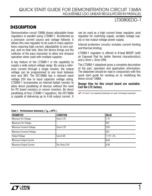
QUICK START GUIDE FOR DEMONSTRATION CIRCUIT 1368AADJUSTABLE LDO LINEAR REGULATORS IN PARALLELLT3080EDD-1 DESCRIPTIONDemonstration circuit 1368A shows adjustable linear regulators in parallel using LT3080-1. Architected as a precision current source and voltage follower, it allows this new regulator to be used in many applica-tions requiring high current, adjustability to zero out-put, and no heat sink. Also the device brings out the collector of the pass transistor to allow low dropout operation when used with multiple supplies.A key feature of the LT3080-1 is the capability to supply a wide output voltage range. By using a refer-ence current through a single resistor, the output voltage can be programmed to any level between zero and 36V. The DC1368A has a reduced input voltage 25V due to input capacitor voltage rating. LT3080-1 incorporates an internal ballast resistor to allow direct paralleling of devices without the need for PC board resistors or sensor resistors. By direct paralleling of four LT3080-1 regulators, the DC1368A is capable of delivering up to 4.4A output current. It can be used as a high current linear regulator, post regulator for switching supply, variable voltage sup-ply or low output voltage power supply.Internal protection circuitry includes current limiting and thermal limiting.LT3080-1 regulator is offered in 8-lead MSOP (with an Exposed Pad for better thermal characteristics) and a 3mm × 3mm DFN.The LT3080-1 datasheet gives a complete description of the part, operation and application information. The datasheet should be read in conjunction with this quick start guide for working on or modifying the demo circuit 1368A.Design files for this circuit board are available. Call the LTC factory., LTC and LT are registered trademarks of Linear Technology Corporation.Table 1.Performance Summary ( T A = 25o C )PARAMETER CONDITION VALUE Minimum Vin Voltage Vout=1.2V 1.7V Maximum Vin Voltage 25V Minimum Vcontrol Voltage Vout=1.2V 2.8V Maximum Vcontrol Voltage 25V Output Voltage Iout=4.4A 1.17V ±3% Minimum Output Current 4mA Maximum Output Current Vin-Vout<2.5V 4.4AQUICK START PROCEDUREThe DC1368A is easy to set up to evaluate the per-formance of the LT3080-1. Refer to Figure 1. for proper measurement equipment setup and following the procedures below: 1.Apply 1.7V across Vin (to Gnd), and 2.8V across Vcontrol. Draw 4.4A of load current. The measured Vout should be 1.17V ± 3% (1.13V to 1.21V).2.Vary Vin from 1.7V to 25V, Vcontrol from 2.8V to 25V and the load current from 4mA to 4.4A. Vout should measure 1.19V ± 5% (1.13V to 1.25V).Note: Make sure the power dissipation is limited be-low the thermal limit.Figure 1. Proper Measurement Equipment SetupFigure 2. Measuring Input or Output RippleINPUT VOLTAGE RANGEThe guaranteed Vin dropout voltage is 0.5V at 4.4A, the guaranteed Vcontrol dropout voltage is 1.6V at 4.4A. The maximum Vin and maximum Vcontrol is reduced to 25V due to the input capacitor voltage rat-ing.DUAL SUPPLY OR SINGLE SUPPLYUse two separate supplies for Vin and Vcontrol, a low dropout voltage can be achieved on the Vin pin and the power dissipation is minimized. Alternatively, Tying the Vcontrol to Vin through a zero ohm jump resistor R1 on board, a single supply is sufficient to drive the demo circuit 1368A. AVOID USING A LONG WIRE TO TIE VCONTROL AND VIN.OUTPUT CURRENTThe output current will decrease at high input-to-output differential. The actual current output is further limited by the thermal shutdown function, which is related to the board thermal dissipation.THERMAL IMAGEAn example thermal image shows the temperature distribution on board. The test is done in still air at room tempera-ture with average 2.0W power dissipation in each LT3080-1.BYPASS CAPACITORSince the SET pin is a high impedance node, unwanted signals may couple into the SET pin and cause erratic behavior. This will be most noticeable when operating with minimum output capacitors at full load current. The easiest way to remedy this is to bypass the SET pin with a small amount of capacitance from SET to ground, 10pF to 20pF is sufficient. A 0.01uF bypasscapacitor is used on the demo board to provide a low-noise output. Please refer to datasheet for details.。
Eaton NGS308033E商品说明书
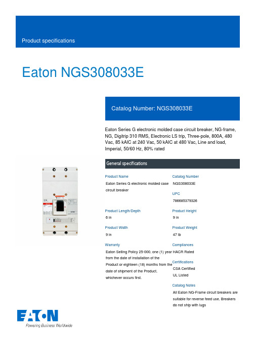
Eaton NGS308033EEaton Series G electronic molded case circuit breaker, NG-frame, NG, Digitrip 310 RMS, Electronic LS trip, Three-pole, 800A, 480 Vac, 85 kAIC at 240 Vac, 50 kAIC at 480 Vac, Line and load, Imperial, 50/60 Hz, 80% ratedGeneral specificationsEaton Series G electronic molded case circuit breakerNGS308033E 7866853793266 in9 in9 in 47 lb Eaton Selling Policy 25-000, one (1) year from the date of installation of theProduct or eighteen (18) months from thedate of shipment of the Product,whichever occurs first.HACR Rated CSA CertifiedUL ListedAll Eaton NG-Frame circuit breakers are suitable for reverse feed use, Breakers do not ship with lugsProduct NameCatalog NumberUPCProduct Length/Depth Product Height Product Width Product Weight WarrantyCompliancesCertificationsCatalog NotesSeries G50 kAIC at 480 Vac 85 kAIC at 240 VacComplete breakerNGNG80% ratedComplete breakerLine and load480 Vac800 AElectronic LSThree-pole Application of Multi-Wire Terminals for Molded Case Circuit Breakers Application of Tap Rules to Molded Case Breaker TerminalsMotor protection circuit breakers product aidHigh performance operating handles for Series G circuit breakers product aidStrandAble terminals product aidPlug-in adapters for molded case circuit breakers product aidMOEM MCCB Product Selection GuideSeries G MCCB quick selectorCircuit breaker motor operators product aidCurrent limiting molded case circuit breaker module product aidMulti-wire lugs product aidCurrent limiting molded case circuit breaker module for series G, JG and CLSeries G Molded Case Circuit Breakers - Quick SelectorPower metering and monitoring with Modbus RTU product aidMolded case circuit breakers providing higher levels of selective coordination product aidComprehensive circuit protection for control panel applicationsJ-Frame 310+ and L-Frame 310+ Molded-case circuit breakers Breaker service centersSeries G Terminations and AccessoriesEaton's Volume 4—Circuit ProtectionMolded case circuit breakers catalogNG-frame Molded Case Circuit Breaker DrawingInstruction Leaflet for Drawout Cassette for NG Frame Circuit BreakersMOEM MCCB product selection guideNG and ND-Frame molded case circuit breakersEaton Specification Sheet - NGS308033ESeriesInterrupt ratingTypeFrameCircuit breaker type RatingCircuit breaker frame type TerminalsVoltage rating Amperage RatingTrip TypeNumber of poles Application notesBrochuresCatalogsDrawingsInstallation instructions Specifications and datasheetsTechnical service bulletinsEaton Corporation plc Eaton House30 Pembroke Road Dublin 4, Ireland © 2023 Eaton. All Rights Reserved. Eaton is a registered trademark.All other trademarks areproperty of their respectiveowners./socialmediaSeries G N-Frame 320-1600A, 240-690V Time Current Curves。
Eaton NGH308036E商品说明书

Eaton NGH308036EEaton Series G electronic molded case circuit breaker, NG-frame, NG, Digitrip 310 RMS, Electronic LSIG trip, Three-pole, 800A, 480 Vac, 100 kAIC at 240 Vac, 65 kAIC at 480 Vac, Line and load, Imperial, 50/60 Hz, 80% ratedGeneral specificationsEaton Series G electronic molded case circuit breakerNGH308036E 7866853792036 in9 in9 in 47 lb Eaton Selling Policy 25-000, one (1) year from the date of installation of theProduct or eighteen (18) months from thedate of shipment of the Product,whichever occurs first.HACR Rated CSA CertifiedUL ListedAll Eaton NG-Frame circuit breakers are suitable for reverse feed use, Breakers do not ship with lugsProduct NameCatalog NumberUPCProduct Length/Depth Product Height Product Width Product Weight WarrantyCompliancesCertificationsCatalog NotesSeries G65 kAIC at 480 Vac 100 kAIC at 240 VacComplete breakerNGNG80% ratedComplete breakerLine and load480 Vac800 AElectronic LSIGThree-pole Application of Tap Rules to Molded Case Breaker Terminals Application of Multi-Wire Terminals for Molded Case Circuit BreakersMulti-wire lugs product aidMOEM MCCB Product Selection GuideSeries G MCCB quick selectorMolded case circuit breakers providing higher levels of selective coordination product aidSeries G Molded Case Circuit Breakers - Quick SelectorCurrent limiting molded case circuit breaker module for series G, JG and CLCircuit breaker motor operators product aidCurrent limiting molded case circuit breaker module product aidHigh performance operating handles for Series G circuit breakers product aidPlug-in adapters for molded case circuit breakers product aid StrandAble terminals product aidPower metering and monitoring with Modbus RTU product aid Comprehensive circuit protection for control panel applicationsMotor protection circuit breakers product aidJ-Frame 310+ and L-Frame 310+ Molded-case circuit breakers Breaker service centersSeries G Terminations and AccessoriesMolded case circuit breakers catalogEaton's Volume 4—Circuit ProtectionNG-frame Molded Case Circuit Breaker DrawingInstruction Leaflet for Drawout Cassette for NG Frame Circuit BreakersNG and ND-Frame molded case circuit breakersMOEM MCCB product selection guideEaton Specification Sheet - NGH308036ESeriesInterrupt ratingTypeFrameCircuit breaker type RatingCircuit breaker frame type TerminalsVoltage rating Amperage RatingTrip TypeNumber of poles Application notesBrochuresCatalogsDrawingsInstallation instructions Specifications and datasheetsTechnical service bulletinsEaton Corporation plc Eaton House30 Pembroke Road Dublin 4, Ireland © 2023 Eaton. All Rights Reserved. Eaton is a registered trademark.All other trademarks areproperty of their respectiveowners./socialmediaSeries G N-Frame 320-1600A, 240-690V Time Current Curves Selling Policy 25-000 - Distribution and Control Products and Services Warranty guides。
总线式步进电机驱动器SE-30807C说明书
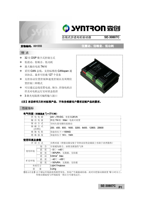
【注】本说明书只针对标准产品,不包含根据客户需求定制产品的要求。
电气性能(环境温度Tj =25℃时)供 电 电 源 24V ~70VDC ,容量0.2KVA 输 出 电 流 峰值7A/相(Max )电流可设置 驱 动 方 式 空间矢量双极恒流驱动 励 磁 方 式(步/转) 200,400,800,1600,3200,6400,12800,25600绝 缘 电 阻 常温常压下>100M Ω 绝 缘 强 度 常温常压下1KV ,1Min使用环境及参数冷 却 方 式 自然对流(将驱动器安装于导热良好的金属面上有助于改善散热)使用环境场 合 尽量避免粉尘、油雾及腐蚀性气体 温 度 -5℃~+40℃湿 度 <80%RH ,无凝露,无结霜 震 动 5.9m/s 2 Max 贮存环境温 度 -40℃~+55℃湿 度 <93%RH ,无凝露,无结霜外形尺寸 135×77×46mm 重 量 0.2Kg【提示注意】由于储运环境温度的剧烈变化,容易产生凝露或结霜,此时应把驱动器放置12小时以上, 待驱动器温度与环境温度一致后方可通电运行。
32位DSP 数字式控制方式 低震动、低噪音、低功耗最大输出电流7A/相 采用CAN 总线,支持标准的CANopen 通讯协议。
最多可挂载127个设备 支持协议位置控制和速度控制以及周期位置控制三种模式 可以通过总线设置电流、细分、控制电机启停及对电机运行实时状态监控 3路光电隔离可编程输入接口 特 点 性能指标 总线式步进电机驱动器 SE-30807C货物编码:001555显著特点采用32位DSP 为内核的全数字控制方式,先进的空间矢量算法优化低速振动和高速性能,可以实现多种电机的自适应匹配寻优控制方法,软件更新、升级方便。
采用CAN 总线,支持标准的CANopen 通讯协议。
最多可挂载127个设备,支持协议位置控制和速度控制以及周期位置控制三种模式。
通过总线通讯,用户不但可以读取驱动器的运行状态,修订设置参数,而且还可以通过总线模式实现对步进电机速度以及位置(包括绝对位置指令和相对位置指令)的控制,极大地方便了组网的应用。
Philips SHB3060 SHB3080 耳机用户手册说明书

Quick start guide
EN 3
3 Get started
Charge your headphones
Note •• Before you use your headphones for the first time,
charge the battery for 5 hours for optimum battery capacity and lifetime.
2
Hearing Safety
2
General information
2
2 Your Bluetooth wireless headphones 3
What's in the box
3
Other devices
3
Overview of your Bluetooth wireless
headphones
5
Wear your headset
6
5 Technical data
7
6 Notice
8
Notice of compliance
8
Disposal of your old product and battery 8
Trademarks
9
7 Frequently asked questions
10
EN 1
Tip •• Normally, a full charge takes 3 hours.
Pair the headphones with your mobile phone
Before you use the headphones with your mobile phone for the first time, pair it with a mobile phone. A successful pairing establishes a unique encrypted link between the headphones and mobile phone.The headphones store the last 4 devices in the memory. If you try to pair more than 4 devices, the earliest paired device is replaced by the new one.
戴尔 OptiPlex 3080 微型机防尘滤网安装指南说明书

OptiPlex 3080 Micro Dust Filter Install GuideNotes, cautions, and warningsA NOTE indicates important information that helps you make better use of your product.A CAUTION indicates either potential damage to hardware or loss of data and tells you how to avoidA WARNING indicates a potential for property damage, personal injury, or death.© 2020 Dell Inc. or its subsidiaries. All rights reserved. Dell, EMC, and other trademarks are trademarks of Dell Inc. or its subsidiaries. Other trademarks may be trademarks of their respective owners.Chapter 1: Before you begin (4)Chapter 2: Dust Filter for OptiPlex Micro (5)Chapter 3: After installing the accessory (6)Chapter 4: Getting help (7)Contacting Dell (7)Contents3Before you beginSteps1.Save and close all open files and exit all open applications.2.Shut down your system: Click Start > Power > Shut down .If you are using a Linux operating system, see the documentation of your operating system for shut-down3.Disconnect your system and all attached devices from their electrical outlets.4.Disconnect all attached network devices and peripherals, such as keyboard, mouse, and monitor from your system.To disconnect a network cable, first unplug the cable from your system and then unplug the cable5.If the system unit or the adapter is being installed on the monitor:a.Disconnect the power and all the display cables from the monitor.b.Remove the stand from the monitor and place the monitor on a clean and soft surface.4Before you beginDust Filter for OptiPlex Micro The dust filter for the OptiPlex 3080 Micro helps protect the system from fine dust particles. After installation, you can set a pre-boot reminder in the BIOS to clean or replace the dust filter at customized time interval using the interval setting in the BIOS.Steps1.Follow the instructions in before you begin.2.Align the top edge of the dust filter with the top edge of the system.3.Press the lower edge of the dust filter to close over the system.4.Gently press down to ensure that the filter fits snugly onto the system.5.Follow the instructions in after installing the accessory.6.Restart the system and press F2 at the Dell splash screen to enter the BIOS Setup menu.7.In the BIOS Setup menu, go to System Configuration > Dust Filter Maintenance and select from any of the followingDefault setting: Disabled.Alerts are generated only during a system reboot and not during normal operating system operation.To clean the dust filter, brush or gently vacuum and then wipe down the external surfaces with a moist cloth.Dust Filter for OptiPlex Micro5After installing the accessorySteps1.Replace all screws and ensure that no stray screws remain.2.Connect any external devices, peripherals, or cables you removed before working on your system.3.Connect your system and all attached devices to their electrical outlets.4.Turn on your system.6After installing the accessoryGetting help Topics:•Contacting DellContacting DellPrerequisitesIf you do not have an active Internet connection, you can find contact information on your purchase invoice, packingAbout this taskDell provides several online and telephone-based support and service options. Availability varies by country and product, and some services may not be available in your area. To contact Dell for sales, technical support, or customer service issues:Steps1.Go to /support.2.Select your support category.3.Verify your country or region in the Choose a Country/Region drop-down list at the bottom of the page.4.Select the appropriate service or support link based on your need.Getting help7。
NSA-3080日常维护手册24页word
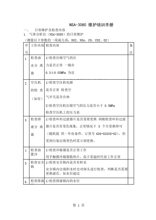
NSA-3080 维护培训手册一、日常维护及检查内容1. 气体分析仪(NSA-3080)的日常维护定概述:仪器的校准建议每两周进行一次(根据国家环境保护总局《HJ/75-2007》之规定每 15 天应进行一次标定),通常情况下(仪表间内温湿度稳定)仪表漂移不会超过 2%F。
S/ 月,如使用者对准确度有怀疑,或有其他需要可按需随时标定。
1 标定的准备工作:首先准备对 URA-208 气体分析仪的操作面板进行操作测量界面在测量界面下按《F2》键进入菜单界面菜单界面将光标移动到“校正条件”按《ENT》键进入校正条件界面校正界面-1根据铝瓶上标准气体的名称和浓度输入到图示界面中的相应气体跨度上(如本图所示,SO2 的跨度气体浓度是286mg/m3。
如需要调整,按《+》《-》键进行调整,调整结束后按《ENT》键进行确认。
(通常情况下,界面中已按照量程设定了所需的浓度值,因此数值调节范围不大。
如需调整的数字与当前值偏差较多,请先按住《F1》健不动按《ENT》键,此时会在数字底部出现闪烁光标,按《←》《→》调节闪烁光标到所需要变更的数字下,再按《+》《-》键进行调整,调整结束后按《ENT》键进行确认即可)标准气体浓度的换算:当标准气体铝瓶上的单位是mg/m3 时,可按标气瓶上的数据直接输入。
当标准气体铝瓶上的单位是10-6 或ppm 时,请按下列公式将浓度进行换算,将换算后的气体浓度输入到分析仪中。
SO2: 1ppm(1*10-6)=64/22.4=2.86 mg/m3NO:1ppm(1*10-6)=30/22.4=1.34 mg/m3CO:1ppm(1*10-6)=28/22.4=1.25 mg/m3另当NO 作为NOx 计算排放量时,应以NO2 计算。
故NOx 浓度为NO 浓度的校正界面-2O2 的跨度根据所在地空气中的O2 含量设定,通常情况下海拔500m 以下时为(20.8%-21%),海拔越低越接近21%;校正界面-3校正界面-4校正界面-5校正界面-6校正条件4、5、6 分别为导入标准气体的时间和稳定、标定时间等参数,可参照《URA-208》说明书或其上显示的中文含义理解,不再详述(如不了解,保持默认设置即可)校正界面-7校正允许范围是设定仪表两次标定的最大偏差,主要是为了防止出现标定不当,或标气用尽等情况令仪表测量失真。
Philips SHB3080BLK 无线蓝牙耳机用户手册说明书

PhilipsWireless Bluetooth®headphones32mm drivers/closed-backOn-earSHB3080BK Wireless powerful bassThe Philips SHB3080 wireless headphones with Bluetooth connectivity is inspired by DJheadphones and designed for aspiring artists. Enjoy hours of music or take calls in easycomfort, thanks to its smart, portable and foldable design.Powerful sound•32 mm high intesity drivers for clear and powerful bass•Closed type acoustics provide good sound isolationMake life more convenient•Bluetooth technology for unwired freedom and convenience•Flat folding design for easy storage on the go•Wireless control and enjoyment of music and callsComfortable for long use•Adjustable earshells and headband fit everyone•Soft breathable ear cushions for long listening sessionsIssue date 2020-07-08Version: 2.0.712 NC: 8670 001 27062EAN: 69 25970 70532 5© 2020 Koninklijke Philips N.V.All Rights reserved.Specifications are subject to change without notice. Trademarks are the property of Koninklijke Philips N.V. or their respective HighlightsWireless Bluetooth® headphones32mm drivers/closed-back On-earSpecifications32mm speaker drivers32mm high-powered drivers deliver clear and powerful bass.Adjustable earshells, headbandAdjustable earshells and headband adapts to fit your head.Bluetooth technologyPair your headphones with any Bluetooth device for crystal clear music enjoyment – wirelessly.Closed type acousticsClosed type acoustics provide good sound isolation, blocking out ambient noise.Flat folding designMade to give you the best experience on the go, these headphones can be folded away for perfect portability and easy storage.Soft ear cushionsSoft breathable ear cushions for long listening sessions and comfort.Wireless music and callsSimply pair your smart device with your headphones using Bluetooth and enjoy the freedom and pleasure of crystal clear music and phone calls – without the hassle of wires.Design•Color:BlackAccessories•Quick start guide: Included•USB cable: Included for chargingConnectivity•Bluetooth profiles: A2DP, AVRCP, HFP, HSP •Maximum range: Up to 15m mConvenience•Call Management: Answer/End Call, Reject Call, Microphone mute, Call on Hold, Switch between call and music, Switch between 2 calls •Volume controlPower•Battery Type:LI-Polymer •Music play time: 11* hr •Standby time: 200* hrs •Talk time: 11* hrSound•Frequency range: 10 - 22 000Hz •Impedance:24ohm•Magnet type: Neodymium•Maximum power input: 30 mW •Speaker diameter: 32 mm •Sensitivity: 106 dB•Acoustic system: ClosedOuter Carton•Gross weight: 2.006 lb •Gross weight: 0.91 kg•GTIN: 1 69 25970 70532 2•Outer carton (L x W x H): 21 x 17 x 25.5 cm •Outer carton (L x W x H): 8.3 x 6.7 x 10.0 inch •Nett weight: 0.933 lb •Nett weight: 0.423 kg•Number of consumer packagings: 3•Tare weight: 0.487 kg •Tare weight: 1.074 lbPackaging dimensions•Packaging dimensions (W x H x D): 19.5 x 22 x 5 cm•Packaging dimensions (W x H x D): 7.7 x 8.7 x 2.0 inch•EAN: 69 25970 70532 5•Gross weight: 0.242 kg •Gross weight: 0.534 lb •Nett weight: 0.311 lb •Nett weight: 0.141 kg•Number of products included: 1•Packaging type: Carton •Tare weight: 0.223 lb •Tare weight: 0.101 kg•Type of shelf placement: Both Product dimensions•Product dimensions (W x H x D): 6.1 x 6.3 x 2.8 inch•Product dimensions (W x H x D): 15.5 x 16 x 7 cm •Weight: 0.311 lb •Weight: 0.141 kg*Actual results may vary。
佳能Canon 经济型学生一体机 MG3080 E478 E478R使用说明书
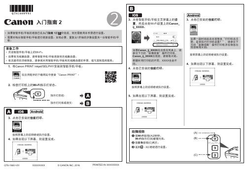
XXXXXXXX © CANON INC. 2016
2
入门指南 2
点击已安装的 如果出现以下屏幕,则设置完成。
1. 将Canon PRINT Inkjet/SELPHY 安装到智能手机/平板。
在应用程序的下载网站中搜索“Canon PRINT ”。
按照屏幕上的说明继续执行设置。
故障排除
a 按Wi-Fi 按钮(A)2秒钟。
Wi-Fi 指示灯(B)缓慢闪烁。
b 按彩色按钮(C)两次。
c 返回 - 3以继续进行设置。
• 如果智能手机/平板的连接已在入门指南 1的
中完成,则无需使用本手册进行设置。
• 需要对每台智能手机/平板进行连接设置。
如有必要,重复从1开始的步骤设置另一台智能手机/平板。
按照屏幕上的说明继续执行设置。
如果Canon_ij_XXXX 未出现在列表上,请参见下方的“故障排除”操作打印机,Canon_ij_XXXX 出现前,请稍等片刻。
根据所用打印机的不同,XXXX 也会不同。
如果一段时间后未出现信息“打印机未注册。
是否执行打印机设置?”,请参见下方的“故障排除”操作打印机并在信息出现前稍等片刻。
2. 检查打印机上的Wi-Fi 指示灯状态。
如果出现以下屏幕,则设置完成。
QT6-1660-V01PRINTED IN XXXXXXXX。
电泳NGC308036E电子封闭电路保护器系列G说明书
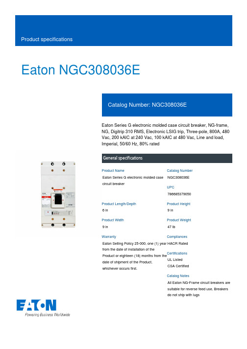
Eaton NGC308036EEaton Series G electronic molded case circuit breaker, NG-frame, NG, Digitrip 310 RMS, Electronic LSIG trip, Three-pole, 800A, 480 Vac, 200 kAIC at 240 Vac, 100 kAIC at 480 Vac, Line and load, Imperial, 50/60 Hz, 80% ratedGeneral specificationsEaton Series G electronic molded case circuit breakerNGC308036E 7866853790506 in9 in9 in 47 lb Eaton Selling Policy 25-000, one (1) year from the date of installation of theProduct or eighteen (18) months from thedate of shipment of the Product,whichever occurs first.HACR Rated UL ListedCSA CertifiedAll Eaton NG-Frame circuit breakers are suitable for reverse feed use, Breakers do not ship with lugsProduct NameCatalog NumberUPCProduct Length/Depth Product Height Product Width Product Weight WarrantyCompliancesCertificationsCatalog NotesSeries G100 kAIC at 480 Vac 200 kAIC at 240 VacComplete breakerNGNG80% ratedComplete breakerLine and load480 Vac800 AElectronic LSIGThree-pole Application of Multi-Wire Terminals for Molded Case Circuit Breakers Application of Tap Rules to Molded Case Breaker TerminalsCurrent limiting molded case circuit breaker module for series G, JG and CLMulti-wire lugs product aidStrandAble terminals product aidMolded case circuit breakers providing higher levels of selective coordination product aidComprehensive circuit protection for control panel applicationsPower metering and monitoring with Modbus RTU product aidHigh performance operating handles for Series G circuit breakers product aidMOEM MCCB Product Selection GuideMotor protection circuit breakers product aidCircuit breaker motor operators product aidPlug-in adapters for molded case circuit breakers product aidCurrent limiting molded case circuit breaker module product aidSeries G MCCB quick selectorSeries G Terminations and AccessoriesBreaker service centersJ-Frame 310+ and L-Frame 310+ Molded-case circuit breakersMolded case circuit breakers catalogEaton's Volume 4—Circuit ProtectionNG-frame Molded Case Circuit Breaker DrawingInstruction Leaflet for Drawout Cassette for NG Frame Circuit BreakersMOEM MCCB product selection guideNG and ND-Frame molded case circuit breakersEaton Specification Sheet - NGC308036ESeries G N-Frame 320-1600A, 240-690V Time Current CurvesSeriesInterrupt ratingTypeFrameCircuit breaker type RatingCircuit breaker frame type TerminalsVoltage rating Amperage RatingTrip TypeNumber of poles Application notesBrochuresCatalogsDrawingsInstallation instructions Specifications and datasheetsTechnical service bulletinsEaton Corporation plc Eaton House30 Pembroke Road Dublin 4, Ireland © 2023 Eaton. All Rights Reserved. Eaton is a registered trademark.All other trademarks areproperty of their respective/socialmediaSelling Policy 25-000 - Distribution and Control Products and Services Warranty guides。
Eaton HFD3080LS22型号的Eaton Series C完整封闭电路保护器说明说明书
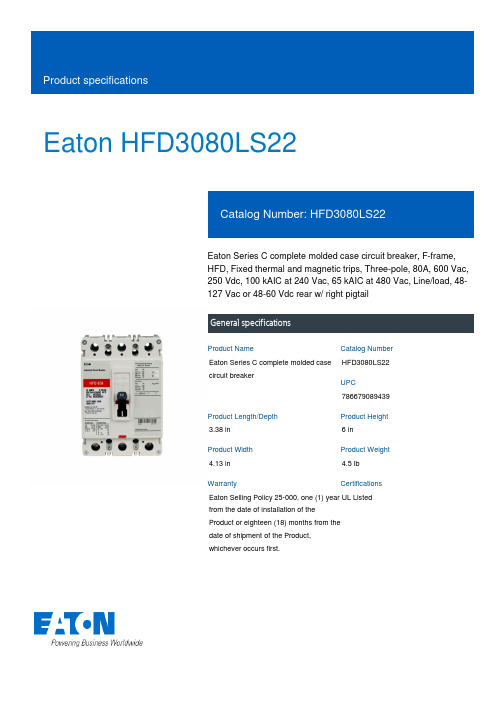
Eaton HFD3080LS22Eaton Series C complete molded case circuit breaker, F-frame, HFD, Fixed thermal and magnetic trips, Three-pole, 80A, 600 Vac, 250 Vdc, 100 kAIC at 240 Vac, 65 kAIC at 480 Vac, Line/load, 48-127 Vac or 48-60 Vdc rear w/ right pigtailGeneral specificationsEaton Series C complete molded case circuit breakerHFD3080LS227866790894393.38 in 6 in4.13 in 4.5 lb Eaton Selling Policy 25-000, one (1) year from the date of installation of the Product or eighteen (18) months from the date of shipment of the Product, whichever occurs first.UL Listed Product NameCatalog Number UPCProduct Length/Depth Product Height Product Width Product Weight WarrantyCertificationsSeries C65 kAIC at 480 Vac100 kAIC at 240 VacFHFD48-127 Vac or 48-60 Vdc right pigtail rear 50/60 HzComplete breakerLine and load600 Vac, 250 Vdc80 AFixed thermal, fixed magneticThree-pole Application of Multi-Wire Terminals for Molded Case Circuit Breakers Application of Tap Rules to Molded Case Breaker TerminalsUL listed 100%-rated molded case circuit breakersCircuit breaker motor operators product aidMotor protection circuit breakers product aidStrandAble terminals product aidMulti-wire lugs product aidCurrent limiting Series C molded case circuit breakers product aid MOEM MCCB Product Selection GuidePlug-in adapters for molded case circuit breakers product aidPower metering and monitoring with Modbus RTU product aid Counterfeit and Gray Market Awareness GuideBreaker service centersEaton's Volume 4—Circuit ProtectionMolded case circuit breakers catalogTime Current Curves for Series C® F-Frame Circuit BreakersInstallation Instructions for EHD, EDB, EDS, ED, EDH, EDC, FDB, FD, HFD, FDC, HFDDC Circuit Breakers and Molded Case SwitchesCircuit Breakers ExplainedCircuit breakers explainedSeries C F-Frame molded case circuit breakersSeries C J-Frame molded case circuit breakers time current curvesEaton Specification Sheet - HFD3080LS22Series C G-Frame molded case circuit breakers time current curves MOEM MCCB product selection guideSelling Policy 25-000 - Distribution and Control Products and ServicesSeriesInterrupt ratingFrameCircuit breaker type Shunt tripFrequency ratingCircuit breaker frame type TerminalsVoltage rating Amperage RatingTrip TypeNumber of poles Application notesBrochuresCatalogsDrawingsInstallation instructions MultimediaSpecifications and datasheets Warranty guidesEaton Corporation plc Eaton House30 Pembroke Road Dublin 4, Ireland © 2023 Eaton. All Rights Reserved. Eaton is a registered trademark.All other trademarks areproperty of their respectiveowners./socialmedia。
森创 SH-30806N 三相混合式步进电机细分驱动器 说明书
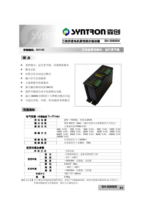
电气性能(环境温度Tj =25℃时)供 电 电 源 24V ~ 70VDC ,容量0.2KVA 输 出 电 流 峰值6A/相(Max )(输出电流可由面板拨码开关设定)驱 动 方 式 正弦波恒流PWM 控制励 磁 方 式 400 步/转, 500 步/转, 600步/转, 800 步/转,1000步/转1600 步/转,2000步/转,3200步/转, 4000步/转,5000步/转6000 步/转,6400步/转,7500步/转,8000步/转,10000步/转30000步/转绝 缘 电 阻 在常温常压下>500M Ω 绝 缘 强 度在常温常压下0.5KV ,1Min使用环境及参数冷 却 方 式 自然对流场 合 尽量避免粉尘、油雾及腐蚀性气体 温 度 -5℃~+40℃湿 度 <80%RH ,无凝露,无结霜 使用环境震 动 5.9m/s 2 Max 温 度 -40℃~+55℃贮存环境湿 度 <93%RH ,无凝露,无结霜外形尺寸 135×77×46mm 重 量 0.5Kg【提示注意】由于储运环境温度的剧烈变化,容易产生凝露或结霜,此时应把驱动器放置12小时以上, 待驱动器温度与环境温度一致后方可通电运行。
柔性细分,运行更平稳,有效降低噪音 断电记忆 内置点位自动运行模式 输入信号光电隔离 正弦波细分恒流驱动 最大输出驱动电流6A/相 提供节能的自动半电流锁定功能最大30000步/转的十六种细分模式可选 可适应共阳、共阴、单/双脉冲多种模式 特 点 性能指标三相步进电机柔性细分驱动器 SH-30806N货物编码:001105显著特点采用了独创的柔性细分概念,使驱动器无论设置何种细分电机都可保持最佳的运行性能,极大的改善了平稳性和噪音。
即使用户由于控制系统输出脉冲频率的限制不能采用较高的细分选择,也可以获得低速平稳性和高速性的兼得,从而降低对控制系统得要求,有利于降低系统得整体成本提高性能。
Z3080电气、液压控制说明

中捷Z3080X25 摇臂钻床电气控制说明本文件适用于Z3080X25型摇臂钻床。
本机床执行标准:GB/T4017-1997《摇臂钻床精度检验》标准。
请妥善保存本手册以为日后操作维修之用安全警示◆机床在吊运时及与地基固定之前,切勿松开立柱的夹紧,否则造成机床的倾倒。
◆机床安装后,请将导轨、外立柱等表面的防锈油擦洗干净,并涂30号机油,否则易研伤导轨等表面。
◆试车前务必将夹紧摇臂的菱形块上的放松板拆下,否则摇臂不能松开。
◆接通电源时,请检查电源相序是否正确,否则机床不能正常开动。
◆请按机床上润滑标牌的规定,对机床各部位注油润滑,否则研伤导轨或机件。
◆机床使用过程中摇臂沿着一个方向连续转动不得超过360°,否则将内立柱的电源线拧断造成短路,危及人身安全。
◆主轴自动进给时,主轴移动手柄转动,请操纵者注意远离手柄,否则易碰伤。
◆钻削前切记将摇臂、立柱及主轴箱夹紧,否则易造成人身事故。
◆钻削过程中绝对不可用手清除铁屑和触摸钻头,观察钻削情况时头部与钻头务必保持一定距离,否则危及人身安全。
◆使用该机床的操作者一律不准带手套,女同志一律带安全工作帽(将头发包住),否则易造成人身事故。
◆在钻削过程中发生机床及人身意外情况,应立即按机床面板的总停止按钮,以免发生事故。
禁止1.主轴机动进给时,不允许在主轴行程的上下两个极限位置撞停。
当机动进给接近极限位置时,必须立即手动脱开机动进给,以防止损坏机床。
2.在主轴有效行程范围内(不包含两个极限位置),主轴机动进给允许使用机械定程装置,机动撞停。
◆液压系统及动作本机床的液压系统由操纵机构液压和夹紧机构液压系统所组成。
操纵阀和预选阀装在主轴箱顶部。
主轴转速预选阀和进给量预选阀是16位六通转阀,每个转阀控制着四个差动油缸,实现16级速度变换。
操纵阀是五位六通转阀控制着正转油缸、反转油缸、变速油缸、“空档”油缸及制动油缸。
操纵阀每个位置,其油路状态如下:油路号1 2 3 4 5 6主轴动作正转+ - - - + -反转- + - - + -变速+ + + - + -空档- - - + + -停止- - - - - -注:“+”为高压油“-”为低压油各号油路连通部位:1.正转油缸2.反转油缸3.预选阀4.空档油缸5.油泵出口6.回油口在变速过程中,高压油进入预选阀,推动各变速油缸,带动滑移齿轮变速,同时正反转油缸也分别通过小孔进入高压油,由于正反转油缸的面积不等,(正转大于反转)使压紧摩擦片的拨叉有较小的力压紧正转摩擦片,使得传动链较慢的启动。
- 1、下载文档前请自行甄别文档内容的完整性,平台不提供额外的编辑、内容补充、找答案等附加服务。
- 2、"仅部分预览"的文档,不可在线预览部分如存在完整性等问题,可反馈申请退款(可完整预览的文档不适用该条件!)。
- 3、如文档侵犯您的权益,请联系客服反馈,我们会尽快为您处理(人工客服工作时间:9:00-18:30)。
DCAP-3080发电机监控保护装置
使用说明书
V2.0
北京清华紫光测控有限公司BEIJING TSINGHUA UNISPLENDOUR M&C CO.,LTD.
一.装置使用说明
1.交流电压输入回路:
装置内部设置有4个小PT可同时接受4个0~100V交流电压的输入,其中3个小PT分别接线电压Uab,线电压Ubc及零序电压U0,1个小PT备用。
2.交流电流输入回路:
装置内部设置有7个小CT,可同时接受7个额定为5A或1A的交流电流输入,其中CT1接A相保护电流Ia,CT2接B相保护电流Ib,CT3接C相保护电流Ic,CT5接A相监控电流Ia,CT7接C相监控电流Ic, CT6接零序电流I0,CT4备用。
3.直流电源输入回路:
装置工作电源的接线端子为P+、P-,其中P+为正电源输入端,P-为负电源输入端。
装置控制回路电源的接线端子为L+,L-,其中L+为正电源端,L-为负电源端。
4.开关量输入(遥信)回路:
装置设有12个遥信开关量信号输入端。
用户在使用本装置并对其分配遥信输入端时必须注意以下几点:
① SI1须接断路器位置信号。
② SGP既可用于开关量输入,也可用于GPS对时脉冲。
③ SP1、SP2既可用于开关量输入,也可用于脉冲量输入。
5.开关量输出(遥控)回路:
装置设有9个开关量输出口TS1~TS9。
其中,TS1~TS8输出何种保护(或几种保护的组合)跳闸信号由跳闸表来设定,通过跳闸表可灵活使用TS1~TS8出口。
6.断路器操作回路:
装置设有断路器操作回路并内置防跳继电器及跳合闸回路保持继电器。
7.通讯接口:
本装置带有RS-485通讯接口和光纤接口,其可通过通讯电缆与厂、站监控系统联网构成综合自动化系统,本装置的各种信号和外部遥信信号可通过通讯网上传至综合自动化系统的监控主机。
二.继电保护功能
1.复合电压闭锁方向过流保护
装置设有三段过流保护,当任一相电流大于整定值时,延时动作于出口。
可受复合电压判据控制,每段保护的复合电压判据均可通过软压板进行投退。
2.复合电压判据
过流保护的复压判据为:Umin<U1dz或U2>U2dz
式中,Umin为线电压Uab、Ubc、Uca之最小值,U1dz为复合电压判据低电压定值,U2为
负序电压,U2dz 为复合电压判据负序电压定值 3.低压保护
装置设有低压保护功能,以线电压为判据,当电压Uab 、Ubc 、Uca 均低于整定值时,延时动作于出口。
低压保护可被下列条件自动闭锁:PT 断线;断路器分状态。
4.过压保护
装置设有过压保护功能,以线电压为判据,当任一线电压大于整定值时,延时动作于出口。
5.方向零序过流保护
装置设有方向零序过流保护,方向为指向发电机。
方向零序过流保护的电流判据为:I0>方向零序过流定值。
方向零序过流保护的方向判据为:︒<<︒18000
0I
U
Arg
当零序电压小于5V 时,方向零序过流保护被自动闭锁。
6.零序过压保护
装置设有零序过压保护功能,当零序电压大于整定值时,延时启动出口或不启动出口而只发信号。
启动出口时发事故信号,不启动出口时发预告信号。
7.失磁保护
装置配备简易的失磁保护,失磁保护由电抗Xa 与电抗Xb 确定其动作区,如下图:
失磁保护可被下列条件自动闭锁:断路器分状态;电压Uab<30V 。
8.反时限对称过负荷保护
特性曲线表达式为:
Fs
t ≥ (I/Ip)²-1
其中Ip 为反时限对称过负荷启动电流,Fs 为反时限对称过负荷系数,I 为负荷电流。
9.反时限负序过负荷保护
特性曲线表达式为:
Fs2
t ≥
(I2/Ip2)²-1
Ip2为反时限负序过负荷启动电流,Fs2为反时限负序过负荷系数,I2为负序电流。
10.负序过流保护
用于三相电流不对称保护。
当生负序电流大于负序过流定值时,延时启动出口。
11.逆功率过流保护
装置设有逆功率过流保护功能,其作用是在装置通过计算发现一次回路向系统返送无功功率时,延时启动出口。
逆功率过流保护的电流判据为:φI ≥逆功率过流定值。
逆功率过流保护的方向判据为:︒<<︒-27090αφ
φφ
j e
I U Arg 式中φI 为电流相量, φφ
U 为线电压相量, 下标φ=a 或b 或c ,φφ=bc 或ca 或ab ,α是方向角,一般取值α=45°。
12.低频保护:
装置设有低频保护功能,受低电压闭锁判据和低电流闭锁判据控制,开关位置断开时也闭锁低频保护。
低频保护频率判据:40Hz ≤频率F ≤低频定值
低频保护电压判据:任一线电压大于频率保护电压定值 低频保护电流判据:任一相电流大于频率保护电流定值 13.高频保护:
装置设有高频保护功能,受低电压闭锁判据和低电流闭锁判据控制,开关位置断开时也闭锁高频保护。
高频保护频率判据:频率F>高频定值
高频保护电压判据:任一线电压大于频率保护电压定值 高频保护电流判据:任一相电流大于频率保护电流定值 14. 解列保护:
装置设有解列保护功能,受电压闭锁判据和电流闭锁判据控制,开关位置断开时也闭锁解列保护。
解列保护频率判据:40Hz ≤频率F ≤解列定值
解列保护电压判据:电压Uab 、Ubc 、Uca 均小于解列电压定值 解列保护电流判据:任一相电流大于解列电流定值
15.PT断线报警
检测一相或两相断线:当负序电压大于门槛值(相电压8V)时,延时5秒发PT断线信号。
检测三相断线:当正序电压小于门槛值(相电压30V)时,若任一相有电流(大于0.06In)则延时5秒发PT断线信号。
16.PT断线闭锁
检测到PT断线后,复合电压判据自动退出,但与之相关的过流保护功能被保留;低压保护、逆功率保护被闭锁。
17.CT断线报警
CT断线判据:保护电流中至少有一相电流大于0.1In 且至少有一相电流小于0.06In,延时3秒报CT断线信号。
18.控制回路断线报警
装置设有控制回路断线报警功能。
正电源及跳合闸回路负电源信号,经过光电隔离进入CPU,如果无正电源或跳、合闸回路两个负电源任一个断线则延时2秒报控制回路断线信号。
19.联跳功能
4路联锁跳闸具有现场可编逻辑功能,可灵活运用于各种工艺联锁。
20.综合自动化功能
装置具有RS485数据通信总线和光纤通信接口,可与综合自动化监控系统联网,并可完全实现四遥功能。
本装置的所有动作、报警信息均通过通信网络上报监控主机,所有整定值均可在监控主机上进行设置。
21.动作及告警报告和录波
保护动作时产生事故报警报告,发生告警事件时产生预告报警报告。
每个报告中含事件发生时间,当时的电压电流量等。
每个报告都会及时上传到监控主机予以保存,可随时查看最近发生的事件报告。
动作或告警时可发出事故或预告信号,需手动复归或远方复归。
保护动作可启动录波,但有些事件发生时不启动录波,如过负荷、断线报警、连锁跳闸等。
录波的长度可整定,装置内部缓冲区可支持总长至少20s的多次录波。
录波数据自动上传到监控主机。
三.正常运行显示
正常情况下,装置可显示电压、电流、功率、电度及遥信状态等。
DCAP-3080监控模拟量显示表:
DCAP-3080保护模拟量显示表:PASSWORD=1000
四.菜单说明
1.DCAP-3080监控参数设置菜单:PASSWORD=1111
2.DCAP-3080保护投退设置:PASSWORD=2222
3.DCAP-3080保护定值设置:PASSWORD=2222
4.DCAP-3080跳闸表设置:PASSWORD=2275
说明:“事故报警”和“预告报警”一旦设置出口,即使报警条件消失,出口继电器接点亦不返回,仅当按ENT键后,出口继电器接点才返回。
5.DCAP-3080故障类型分配表
6.DCAP-3080交流模拟量精度校准:PASSWORD=2266
7.出口继电器试验:PASSWORD=1175
通过在机箱面板上操作,可以检测装置出口继电器的动作情况。
输入密码1175并确认,装置进入出口继电器试验菜单。
菜单内的数字1~9分别对应出口继电器TS1~TS9。
通过BIT键和INC键移动光标到希望进行试验的输出继电器对应的数字上,按ENT键确认后,出口继电器动作且对应的指示灯亮。
8.联跳位,位电平设置及脉冲量/开关量选择:PASSWORD=3333
五.装置功能逻辑框图六.装置原理接线图七.装置底板端子图。
