4646-X400 VAC传感器
Schneider Electric ATV61 22kW 三相变速器产品说明书

T h e i n f o r m a t i o n p r o v i d e d i n t h i s d o c u m e n t a t i o n c o n t a i n s g e n e r a l d e s c r i p t i o n s a n d /o r t e c h n i c a l c h a r a c t e r i s t i c s o f t h e p e r f o r m a n c e o f t h e p r o d u c t s c o n t a i n e d h e r e i n .T h i s d o c u m e n t a t i o n i s n o t i n t e n d e d a s a s u b s t i t u t e f o r a n d i s n o t t o b e u s e d f o r d e t e r m i n i n g s u i t a b i l i t y o r r e l i a b i l i t y o f t h e s e p r o d u c t s f o r s p e c i f i c u s e r a p p l i c a t i o n s .I t i s t h e d u t y o f a n y s u c h u s e r o r i n t e g r a t o r t o p e r f o r m t h e a p p r o p r i a t e a n d c o m p l e t e r i s k a n a l y s i s , e v a l u a t i o n a n d t e s t i n g o f t h e p r o d u c t s w i t h r e s p e c t t o t h e r e l e v a n t s p e c i f i c a p p l i c a t i o n o r u s e t h e r e o f .N e i t h e r S c h n e i d e r E l e c t r i c I n d u s t r i e s S A S n o r a n y o f i t s a f f i l i a t e s o r s u b s i d i a r i e s s h a l l b e r e s p o n s i b l e o r l i a b l e f o r m i s u s e o f t h e i n f o r m a t i o n c o n t a i n e d h e r e i n .Product data sheetCharacteristicsATV61HD22N4ZSPEEDDRIVE 30HP,460V,ATV61LEDKEYPADMainRange of product Altivar 61Product or component typeVariable speed driveProduct specific appli-cationPumping and ventilation machine Component name ATV61Motor power kW 22 kW 3 phases at 380...480 V Motor power hp 30 hp 3 phases at 380...480 V Power supply voltage 380...480 V (- 15...10 %)Supply number of phases 3 phasesLine current 50 A for 380 V 3 phases 22 kW / 30 hp 42 A for 480 V 3 phases 22 kW / 30 hp EMC filter Level 3 EMC filterVariant Without remote graphic terminal Assembly style With heat sinkApparent power 32.9 kVA for 380 V 3 phases 22 kW / 30 hp Maximum prospective line Isc22 kA 3 phases Maximum transient cur-rent57.6 A for 60 s 3 phases Nominal switching fre-quency12 kHzSwitching frequency 12...16 kHz with derating factor 1...16 kHz adjustableAsynchronous motor controlVoltage/Frequency ratio, 2 points Voltage/Frequency ratio, 5 pointsFlux vector control without sensor, standardVoltage/Frequency ratio - Energy Saving, quadratic U/fSynchronous motor control profile Vector control without sensor, standard Communication port protocolCANopen ModbusType of polarization No impedance for ModbusOption cardProfibus DP V1 communication card Profibus DP communication card Multi-pump cardModbus/Uni-Telway communication card Modbus TCP communication card Modbus Plus communication card METASYS N2 communication card LonWorks communication card Interbus-S communication card I/O extension cardFipio communication cardEthernet/IP communication card DeviceNet communication cardController inside programmable card CC-Link communication card BACnet communication cardAPOGEE FLN communication cardComplementaryProduct destination Asynchronous motorsSynchronous motorsPower supply voltage limits323...528 VPower supply frequency50...60 Hz (- 5...5 %)Power supply frequency limits47.5...63 HzContinuous output current48 A at 12 kHz, 380 V 3 phases40 A at 12 kHz, 460 V 3 phasesSpeed drive output frequency0.1...599 HzSpeed range 1...100 in open-loop mode, without speed feedbackSpeed accuracy+/- 10 % of nominal slip for 0.2 Tn to Tn torque variation without speed feedback Torque accuracy+/- 15 % in open-loop mode, without speed feedbackTransient overtorque130 % of nominal motor torque, +/- 10 % for 60 sBraking torque30 % without braking resistor<= 125 % with braking resistorRegulation loop Frequency PI regulatorMotor slip compensation AdjustableAutomatic whatever the loadCan be suppressedNot available in voltage/frequency ratio (2 or 5 points)Diagnostic 1 LED red presence of drive voltageOutput voltage<= power supply voltageElectrical isolation Between power and control terminalsType of cable for mounting in an enclosure Without mounting kit : 1-strand IEC cable at 45 °C, copper 90 °C XLPE/EPRWithout mounting kit : 1-strand IEC cable at 45 °C, copper 70 °C PVCWith UL Type 1 kit : 3-strand UL 508 cable at 40 °C, copper 75 °C PVCWith an IP21 or an IP31 kit : 3-strand IEC cable at 40 °C, copper 70 °C PVC Electrical connection L1/R, L2/S, L3/T, U/T1, V/T2, W/T3, PC/-, PO, PA/+, PA, PB terminal 50 mm² /AWG 1/0AI1-/AI1+, AI2, AO1, R1A, R1B, R1C, R2A, R2B, LI1...LI6, PWR terminal 2.5mm² / AWG 14Tightening torque L1/R, L2/S, L3/T, U/T1, V/T2, W/T3, PC/-, PO, PA/+, PA, PB 12 N.m / 106.2 lb.inAI1-/AI1+, AI2, AO1, R1A, R1B, R1C, R2A, R2B, LI1...LI6, PWR 0.6 N.m Supply Internal supply 24 V DC (21...27 V), <= 200 mA for overload and short-circuit pro-tectionInternal supply for reference potentiometer (1 to 10 kOhm) 10.5 V DC +/- 5 %, <=10 mA for overload and short-circuit protectionExternal supply 24 V DC (19...30 V), 30 WAnalogue input number2Analogue input type AI2 software-configurable voltage 0...10 V DC, input voltage 24 V max,impedance 30000 Ohm, resolution 11 bitsAI2 software-configurable current 0...20 mA, impedance 242 Ohm, resolution 11bitsAI1-/Al1+ bipolar differential voltage +/- 10 V DC, input voltage 24 V max, resolu-tion 11 bits + signSampling time Discrete input LI6 (if configured as logic input) 2 ms, +/- 0.5 msDiscrete input LI1...LI5 2 ms, +/- 0.5 msAnalog output AO1 2 ms, +/- 0.5 msAnalog input Al2 2 ms, +/- 0.5 msAnalog input AI1-/Al1+ 2 ms, +/- 0.5 msAbsolute accuracy precision AO1 +/- 1 % for a temperature variation 60 °CAI2 +/- 0.6 % for a temperature variation 60 °CAI1-/Al1+ +/- 0.6 % for a temperature variation 60 °CLinearity error AO1 +/- 0.2 %AI2 +/- 0.15 % of maximum valueAI1-/Al1+ +/- 0.15 % of maximum valueAnalogue output number1Analogue output type AO1 software-configurable logic output 10 V, <= 20 mAAO1 software-configurable voltage, analogue output range 0...10 V DC,impedance 470 Ohm, resolution 10 bitsAO1 software-configurable current, analogue output range 0...20 mA, impedance500 Ohm, resolution 10 bitsDiscrete output number2Discrete output type(R2A, R2B) configurable relay logic NO, electrical durability 100000 cycles(R1A, R1B, R1C) configurable relay logic NO/NC, electrical durability 100000 cy-clesMaximum response time R2A, R2B <= 7 ms, tolerance +/- 0.5 msR1A, R1B, R1C <= 7 ms, tolerance +/- 0.5 ms<= 100 ms in STO (Safe Torque Off)Minimum switching current Configurable relay logic 3 mA at 24 V DCMaximum switching current R1, R2 on resistive load, 5 A at 30 V DC, cos phi = 1, L/R = 0 msR1, R2 on resistive load, 5 A at 250 V AC, cos phi = 1, L/R = 0 msR1, R2 on inductive load, 2 A at 30 V DC, cos phi = 0.4, L/R = 7 msR1, R2 on inductive load, 2 A at 250 V AC, cos phi = 0.4, L/R = 7 ms Discrete input number7Discrete input type(PWR) safety input, 24 V DC, voltage limits <= 30 V, impedance 1500 Ohm(LI6) switch-configurable PTC probe, 0...6, impedance 1500 Ohm(LI6) switch-configurable, 24 V DC, voltage limits <= 30 V, with level 1 PLC,impedance 3500 Ohm(LI1...LI5) programmable, 24 V DC, voltage limits <= 30 V, with level 1 PLC,impedance 3500 OhmDiscrete input logic LI6 (if configured as logic input) positive logic (source), < 5 V (state 0), > 11 V(state 1)LI6 (if configured as logic input) negative logic (sink), > 16 V (state 0), < 10 V(state 1)LI1...LI5 positive logic (source), < 5 V (state 0), > 11 V (state 1)LI1...LI5 negative logic (sink), > 16 V (state 0), < 10 V (state 1) Acceleration and deceleration ramps Automatic adaptation of ramp if braking capacity exceeded, by using resistorLinear adjustable separately from 0.01 to 9000 sS, U or customizedBraking to standstill By DC injectionProtection type Motor thermal protectionMotor power removalMotor motor phase breakDrive thermal protectionDrive short-circuit between motor phasesDrive power removalDrive overvoltages on the DC busDrive overheating protectionDrive overcurrent between output phases and earthDrive line supply undervoltageDrive line supply overvoltageDrive input phase breaksDrive break on the control circuitDrive against input phase lossDrive against exceeding limit speedInsulation resistance> 1 mOhm at 500 V DC for 1 minute to earthFrequency resolution Display unit 0.1 HzAnalog input 0.024/50 HzType of connector Male SUB-D 9 on RJ45 for CANopen1 RJ45 for Modbus on terminal1 RJ45 for Modbus on front facePhysical interface2-wire RS 485 for ModbusTransmission frame RTU for ModbusTransmission rate20 kbps, 50 kbps, 125 kbps, 250 kbps, 500 kbps, 1 Mbps for CANopen9600 bps, 19200 bps for Modbus on front face4800 bps, 9600 bps, 19200 bps, 38.4 Kbps for Modbus on terminalData format8 bits, odd even or no configurable parity for Modbus on terminal8 bits, 1 stop, even parity for Modbus on front faceNumber of addresses 1...247 for Modbus1...127 for CANopenMethod of access Slave for CANopenMarking CEOperating position Vertical +/- 10 degreeProduct weight30 kgWidth240 mmHeight420 mmDepth236 mmEnvironmentNoise level59.9 dB conforming to 86/188/EECDielectric strength5092 V DC between control and power terminals3535 V DC between earth and power terminalsElectromagnetic compatibility Voltage dips and interruptions immunity test conforming to IEC 61000-4-11Radiated radio-frequency electromagnetic field immunity test conforming to IEC61000-4-3 level 3Electrostatic discharge immunity test conforming to IEC 61000-4-2 level 3Electrical fast transient/burst immunity test conforming to IEC 61000-4-4 level 4Conducted radio-frequency immunity test conforming to IEC 61000-4-6 level 3 Standards EN 55011 class A group 2EN 61800-3 environments 1 category C3EN 61800-3 environments 2 category C3EN/IEC 61800-3EN/IEC 61800-5-1IEC 60721-3-3 class 3C1IEC 60721-3-3 class 3S2UL Type 1Product certifications CSAC-TickDNVGOSTNOM 117ULPollution degree 3 conforming to UL 8403 conforming to EN/IEC 61800-5-1Degree of proctection IP54 on lower part conforming to EN/IEC 61800-5-1IP54 on lower part conforming to EN/IEC 60529IP41 on upper part conforming to EN/IEC 61800-5-1IP41 on upper part conforming to EN/IEC 60529IP21 conforming to EN/IEC 61800-5-1IP21 conforming to EN/IEC 60529IP20 on upper part without blanking plate on cover conforming to EN/IEC61800-5-1IP20 on upper part without blanking plate on cover conforming to EN/IEC 60529 Vibration resistance 1.5 mm peak to peak (f = 3...13 Hz) conforming to EN/IEC 60068-2-61 gn (f = 13...200 Hz) conforming to EN/IEC 60068-2-6Shock resistance15 gn for 11 ms conforming to EN/IEC 60068-2-27Relative humidity 5...95 % without dripping water conforming to IEC 60068-2-35...95 % without condensation conforming to IEC 60068-2-3Ambient air temperature for operation50...60 °C with derating factor-10...50 °C without deratingAmbient air temperature for storage-25...70 °COperating altitude1000...3000 m with current derating 1 % per 100 m<= 1000 m without deratingOffer SustainabilitySustainable offer status Green Premium productRoHS (date code: YYWW)Compliant - since 0946 -Schneider Electric declaration of conformity REACh Reference contains SVHC above the threshold -go to CaP for more details Product environmental profile Available Download Product EnvironmentalProduct end of life instructions Available Download End Of Life ManualProduct data sheetATV61HD22N4Z Dimensions DrawingsVariable Speed Drives without Graphic Display TerminalDimensions without Option CardDimensions in mmDimensions in in.Dimensions with 1 Option Card (1)Dimensions in mmDimensions in in.(1) Option cards: I/O extension cards, communication cards or "Controller Inside” programmable card.Dimensions with 2 Option Cards (1)Dimensions in mmDimensions in in.(1) Option cards: I/O extension cards, communication cards or "Controller Inside” programmable card.Product data sheetATV61HD22N4ZMounting and ClearanceMounting RecommendationsDepending on the conditions in which the drive is to be used, its installation will require certain precautions and the use of appropriate accessories.Install the unit vertically:●Avoid placing it close to heating elements●Leave sufficient free space to ensure that the air required for cooling purposes can circulate from the bottom to the top of the unit. ClearanceMounting TypesType A MountingType B MountingType C MountingBy removing the protective blanking cover from the top of the drive, the degree of protection for the drive becomes IP 20.The protective blanking cover may vary according to the drive model (refer to the user guide).Specific Recommendations for Mounting the Drive in an EnclosureVentilationTo ensure proper air circulation in the drive:●Fit ventilation grilles.●Ensure that there is sufficient ventilation. If there is not, install a forced ventilation unit with a filter. The openings and/or fans must providea flow rate at least equal to that of the drive fans (refer to the product characteristics).●Use special filters with IP 54 protection.●Remove the blanking cover from the top of the drive.Dust and Damp Proof Metal Enclosure (IP 54)The drive must be mounted in a dust and damp proof enclosure in certain environmental conditions: dust, corrosive gases, high humidity with risk of condensation and dripping water, splashing liquid, etc.This enables the drive to be used in an enclosure where the maximum internal temperature reaches 50°C.Product data sheetATV61HD22N4ZConnections and SchemaWiring Diagram Conforming to Standards EN 954-1 Category 1, IEC/EN 61508 Capacity SIL1, in Stopping Category 0 According to IEC/EN 60204-1Three-Phase Power Supply with Upstream Breaking via ContactorA1ATV61 driveKM1ContactorL1DC chokeQ1Circuit-breakerQ2GV2 L rated at twice the nominal primary current of T1Q3GB2CB05XB4 B or XB5 A pushbuttonsS1,S2T1100 VA transformer 220 V secondary(1)Line choke (three-phase); mandatory for ATV61HC11Y…HC80Y drives (except when a special transformer is used (12-pulse)).(2)For ATV61HC50N4, ATV61HC63N4 and ATV61HC50Y…HC80Y drives, refer to the power terminal connections diagram.(3)Fault relay contacts. Used for remote signalling of the drive status.(4)Connection of the common for the logic inputs depends on the positioning of the SW1 switch. The above diagram shows the internalpower supply switched to the “source” position (for other connection types, refer to the user guide).(5)There is no PO terminal on ATV61HC11Y…HC80Y drives.(6)Optional DC choke for ATV61H•••M3, ATV61HD11M3X…HD45M3X and ATV61H075N4…HD75N4 drives. Connected in place of thestrap between the PO and PA/+ terminals. For ATV61HD55M3X…HD90M3X, ATV61HD90N4…HC63N4 drives, the choke is supplied with the drive; the customer is responsible for connecting it. For ATV61W•••N4 and ATV61W•••N4C drives, the DC choke is integrated.(7)Software-configurable current (0…20 mA) or voltage (0…10 V) analog input.(8)Reference potentiometer.NOTE: All terminals are located at the bottom of the drive. Fit interference suppressors on all inductive circuits near the drive or connected on the same circuit, such as relays, contactors, solenoid valves, fluorescent lighting, etc.Wiring Diagram Conforming to Standards EN 954-1 Category 1, IEC/EN 61508 Capacity SIL1, in Stopping Category 0 According to IEC/EN 60204-1Three-Phase Power Supply with Downstream Breaking via Switch DisconnectorA1ATV61 driveL1DC chokeQ1Circuit-breakerQ2Switch disconnector (Vario)(1)Line choke (three-phase), mandatory for ATV61HC11Y…HC80Y drives (except when a special transformer is used (12-pulse)).(2)For ATV61HC50N4, ATV61HC63N4 and ATV61HC50Y…HC80Y drives, refer to the power terminal connections diagram.(3)Fault relay contacts. Used for remote signalling of the drive status.(4)Connection of the common for the logic inputs depends on the positioning of the SW1 switch. The above diagram shows the internalpower supply switched to the “source” position (for other connection types, refer to the user guide).(5)There is no PO terminal on ATV61HC11Y…HC80Y drives.(6)Optional DC choke for ATV61H•••M3, ATV61HD11M3X…HD45M3X and ATV61H075N4…HD75N4 drives. Connected in place of thestrap between the PO and PA/+ terminals. For ATV61HD55M3X…HD90M3X, ATV61HD90N4…HC63N4 drives, the choke is supplied with the drive; the customer is responsible for connecting it. For ATV61W•••N4 and ATV61W•••N4C drives, the DC choke is integrated.(7)Software-configurable current (0…20 mA) or voltage (0…10 V) analog input.(8)Reference potentiometer.NOTE: All terminals are located at the bottom of the drive. Fit interference suppressors on all inductive circuits near the drive or connected on the same circuit, such as relays, contactors, solenoid valves, fluorescent lighting, etc.Wiring Diagram Conforming to Standards EN 954-1 Category 3, IEC/EN 61508 Capacity SIL2, in Stopping Category 0 According to IEC/EN 60204-1Three-Phase Power Supply, Low Inertia Machine, Vertical MovementA1ATV61 drive A2Preventa XPS AC safety module for monitoring emergency stops and switches. One safety module can manage the “Power Removal”function for several drives on the same machine. In this case, each drive must connect its PWR terminal to its + 24 V via the safety contacts on the XPS AC module. These contacts are independent for each drive.F1Fuse L1DC choke Q1Circuit-breaker S1Emergency stop button with 2 contacts S2XB4 B or XB5 A pushbutton (1)Power supply: 24 Vdc or Vac, 115 Vac, 230 Vac.(2)S2: resets XPS AC module on power-up or after an emergency stop. ESC can be used to set external starting conditions.(3)Requests freewheel stopping of the movement and activates the “Power Removal” safety function.(4)Line choke (three-phase), mandatory for and ATV61HC11Y…HC80Y drives (except when a special transformer is used (12-pulse)).(5)The logic output can be used to signal that the machine is in a safe stop state.(6)For ATV61HC50N4, ATV61HC63N4 and ATV61HC50Y…HC80Y drives, refer to the power terminal connections diagram.(7)Fault relay contacts. Used for remote signalling of the drive status.(8)Connection of the common for the logic inputs depends on the positioning of the SW1 switch. The above diagram shows the internal power supply switched to the “source” position (for other connection types, refer to the user guide).(9)Standardized coaxial cable, type RG174/U according to MIL-C17 or KX3B according to NF C 93-550, external diameter 2.54 mm /0.09 in., maximum length 15 m / 49.21 ft. The cable shielding must be earthed.(10)There is no PO terminal on ATV61HC11Y…HC80Y drives.(11)Optional DC choke for ATV61H•••M3, ATV61HD11M3X…HD45M3X and ATV61H075N4…HD75N4 drives. Connected in place of the strap between the PO and PA/+ terminals. For ATV61HD55M3X…HD90M3X, ATV61HD90N4…HC63N4 drives, the choke is supplied with the drive; the customer is responsible for connecting it. For ATV61W•••N4 and ATV61W•••N4C drives, the DC choke is integrated.(12)Software-configurable current (0…20 mA) or voltage (0…10 V) analog input.(13)Reference potentiometer.NOTE: All terminals are located at the bottom of the drive. Fit interference suppressors on all inductive circuits near the drive or connected on the same circuit, such as relays, contactors, solenoid valves, fluorescent lighting, etc.Wiring Diagram Conforming to Standards EN 954-1 Category 3, IEC/EN 61508 Capacity SIL2, in Stopping Category 1 According to IEC/EN 60204-1Three-Phase Power Supply, High Inertia MachineA1ATV61 drive A2(5)Preventa XPS ATE safety module for monitoring emergency stops and switches. One safety module can manage the "Power Removal”safety function for several drives on the same machine. In this case the time delay must be adjusted on the drive controlling the motor that requires the longest stopping time. In addition, each drive must connect its PWR terminal to its + 24 V via the safety contacts on the XPS ATE module. These contacts are independent for each drive.F1Fuse L1DC choke Q1Circuit-breaker S1Emergency stop button with 2 contacts S2XB4 B or XB5 A pushbutton (1)Power supply: 24 Vdc or Vac, 115 Vac, 230 Vac.(2)Requests controlled stopping of the movement and activates the “Power Removal” safety function.(3)Line choke (three-phase), mandatory for ATV61HC11Y…HC80Y drives (except when a special transformer is used (12-pulse)).(4)S2: resets XPS ATE module on power-up or after an emergency stop. ESC can be used to set external starting conditions.(5)The logic output can be used to signal that the machine is in a safe state.(6)For stopping times requiring more than 30 seconds in category 1, use a Preventa XPS AV safety module which can provide a maximum time delay of 300 seconds.(7)For ATV61HC50N4, ATV61HC63N4 and ATV61HC50Y…HC80Y drives, refer to the power terminal connections diagram.(8)Fault relay contacts. Used for remote signalling of the drive status.(9)Connection of the common for the logic inputs depends on the positioning of the SW1 switch. The above diagram shows the internal power supply switched to the “source” position (for other connection types, refer to the user guide).(10)Standardized coaxial cable, type RG174/U according to MIL-C17 or KX3B according to NF C 93-550, external diameter 2.54 mm/0.09 in., maximum length 15 m/49.21 ft. The cable shielding must be earthed.(11)Logic inputs LI1 and LI2 must be assigned to the direction of rotation: LI1 in the forward direction and LI2 in the reverse direction.(12)There is no PO terminal on ATV61HC11Y…HC80Y drives.(13)Optional DC choke for ATV61H•••M3, ATV61HD11M3X…HD45M3X and ATV61H075N4…HD75N4 drives. Connected in place of the strap between the PO and PA/+ terminals. For ATV61HD55M3X…HD90M3X, ATV61HD90N4…HC63N4 drives, the choke is supplied with the drive; the customer is responsible for connecting it. For ATV61W•••N4 and ATV61W•••N4C drives, the DC choke is integrated.(14)Software-configurable current (0…20 mA) or voltage (0…10 V) analog input.(15)Reference potentiometer.NOTE: All terminals are located at the bottom of the drive. Fit interference suppressors on all inductive circuits near the drive or connected on the same circuit, such as relays, contactors, solenoid valves, fluorescent lighting, etc.Product data sheet Performance Curves ATV61HD22N4ZDerating CurvesThe derating curves for the drive nominal current (In) depend on the temperature, the switching frequency and the mounting type (A, B or C).For intermediate temperatures (e.g. 55°C), interpolate between 2 curves.X Switching frequencyNOTE: Above 50ºC, the drive should be fitted with a control card fan kit.。
FST600-400 高精度在线式红外温度传感器 产品说明书

高精度在线式红外温度传感器产品说明书(V1.0)湖南菲尔斯特传感器有限公司Hunan Firstrate Sensor Co.,Ltd●重要声明非常感谢您购买菲尔斯特传感器(变送器),我们为您真诚服务到永远。
菲尔斯特追求卓越不凡的品质,更注重良好的售后服务,如有问题,请拔打:400-607-8500(7×24h)。
操作错误会缩短产品的寿命,降低其性能,严重时可能引起意外事故。
请您在使用前务必仔细熟读本说明书。
将本说明书交到最终用户手中。
请妥善保管好说明书,以备需要时查阅。
说明书供参考所用,具体设计外形以实物为准。
●产品概述FST600-400红外测温仪通过红外探测器(热敏探测器和光电探测器)将红外辐射能量测出并转变成电信号,再根据辐射基本定律转换为温度并将温度信号通过显示仪表显示出来,它主要由光学系统、光电探测器、信号放大器及信号处理等部分组成。
FST600-400红外测温仪可用于温度过高或过低、高电压的区域以及高速运转的机械温度的测量,且测量者不必靠近这些特定环境,同时产品反应速度快、灵敏度高。
由于是非接触测量,这样测量过程不会改变被测物体的温度,所以测量结果真实可靠。
●产品特点●无需接触被测目标●方便测量难以接近或移动的目标●反应速度快、精确度高●可满足各种工况场合要求●安装简单,多种测温范围可选●应用范围●电力设备●现代化医疗领域●食品工业●化学工业●建筑行业●机械加工控制领域●技术指标测温范围(℃)-70~380℃可定制输出信号:(4~20)mA,RS485可定制信号线规格:2Wire4Wire供电电压:12-30VDC测温精度:测量值的±2%或±2.5℃(环境温度:23±5°C)光谱范围:8-14um环境温度:(0~+60)°C储存温度:(-20~+80)°C响应时间:300ms(95%)D:S:10:1防护等级:IP65材料:304●电气接口直接出线:红色:电源正(+Vcc)黑色:输出(Iout)红色:电源正(+Vcc)黑色:GND绿色:RS485A白色:RS485B注:具体接线方以线标为准。
常用模拟开关芯片型号与功能和应用介绍

常用模拟开关芯片型号与功能和应用介绍
1.CD4066:
CD4066是一种四路双开关模拟集成电路。
它可以用作高速CMOS开关、模拟信号开关和数字信号开关。
CD4066具有低电平阈值和高通串脉冲响
应等特性,可以通过外部电压来控制其开关状态。
其应用包括模拟开关、
数据路由、模拟选择器和模拟交换等。
2.MAX4617:
MAX4617是一种低电阻四路双开关。
它具有低电阻和低电平失真的特点,可用于模拟交换、模拟多路复用和模拟电流控制等应用。
MAX4617还
具有高速开关时间和广泛的供电电压范围,适用于多种电路设计。
3.ADG601:
ADG601是一种单路、高精度CMOS模拟开关芯片。
它具有低电位失真、低电流和低电压操作的特点,适用于音频信号开关、电量计选择、过程控
制和自动测试设备等应用。
ADG601还具有低串扰和低抖动等特性,可以
提供高品质的信号传输。
这些模拟开关芯片的功能和应用广泛,可以满足不同领域的需求。
它
们在信号传输、数据交换、功率控制和信号处理等方面发挥着重要作用。
无论是工业自动化、通信设备、消费电子产品还是医疗设备,这些模拟开
关芯片都能够提供可靠和精确的信号控制。
因此,选取适合的模拟开关芯
片对于电路设计和系统性能至关重要。
UHA1R-0100L配置和技术参数

iTrust Adapt 1-20kVA UPS是艾默生网络能源有限公司开发的智能化在线式正弦波不间断电源系统,可为用户的精密仪器设备提供可靠、优质的交流电源,采用模块化设计,可以根据需求装配为塔式或机架式,兼容单进单出和三进单出,适用于小型计算机中心、网络间、通信系统、自动控制系统和精密仪器设备的交流供电。
产品特性:超高功率密度超宽输入电压范围输出功率因数高达0.9兼容机架/塔式安装方式出色的节能环保特性完全匹配易睿设计方案输入兼容应三相380V、单相220V支持并联扩展运行,且无需并机插框(最大4台)电池模块化设计,轻松级联扩充后备时间提供LED/LCD(选件)显示功能,且现场可更换支持服务器自动关机功能提供多种监控端口,满足不同监控需求提供丰富机架用选件,方便机架内的配电/监控等功能的一体化实施。
可调单进单出、三进单出产品突出特点超高功率密度,整机2-3U超宽输入电压/频率范围,适应恶劣电网环境输出功率因数高达0.9,带载量提升20-30%效率高达92-94%三相单相兼容,适合多种应用场合兼容机架式/塔式安装方式支持并联扩展运行(最大4台)提供丰富机架选件,方便机架内的配电/监控等功能的一体化实施可平滑接入艾默生易睿TM监控系统出色的节能环保特性输入高功率因数高达0.99,实现高电能利用率整机效率高达92%以上,节能效益明显满足欧盟RoHS环保指令ITA系列UPS的产品定位?适用于服务器机房等区域,保护服务器、网络通信等关键设备完全匹配艾默生易睿TM机房整体方案黑色机身设计突显了与服务器、机柜的和谐搭配ITA系列UPS如何确保供电的高可靠性?双变换在线式设计,市电掉电无中断支持N+X冗余方式,实现系统可靠性的大幅提升DSP全数字控制,输出稳压精度高采用最新IGBT器件,实现输入超宽抗电网波动范围输入标配防浪涌电路,实现卓越的抗电网浪涌能力ITA系列UPS如何带来绿色环保?整机效率高达92%以上,节能效益明显输入功率因数高达0.99,电能利用率高满足欧盟RoHS指令,物料/工艺无有毒物质可调速智能风扇,风扇转速自适应调节,有效节能降噪提供ECO运行模式,效率高达98%,显著节能ITA系列UPS如何为您省钱?高达0.9的输出功率因数,挂接更多负载支持并机扩展运行,且无需并机插框系统效率高,省电、运行成本低功率密度高,占用机架空间小,节省机架数量ITA系列UPS如何方便的维护?超大尺寸LCD和LED显示,各类运行数据/系统状态/历史情况一目了然操作显示面板旋转设计,可随安装方式不同自由调整角度,方便直观ITA系列UPS如何提高方案的可用性?兼容三单/单单(5/10KVA),三单/三三(16/20KVA)多种应用场合支持多达4台的并机,系统容量随意扩充可通过级联电池模块方便地延长后备时间ITA系列UPS如何满足各种监控需求?提供最新USB监控端口提供可采集环境量的SIC网络适配卡,支持服务器自动安全关机功能后台软件兼容多种操作系统(Windows/Linux/HP-UX/Sun Solaris/IBM AIX等) 兼容艾默生机房监控平台SiteMonitor,支持Web监控提供Mib库,方便接入各类NMS网管系统ITA系列UPS如何保护和延长电池组寿命?超宽输入电压/频率范围,有效减少电池放电几率,延长寿命温度补偿功能,减少环境温度对电池寿命的影响超强充电能力,有效缩短电池回充时间电池组节数设置灵活,便于电池系统的利旧(16/20KVA)支持共用电池组(16/20KVA),节省电池投资。
BD46441G中文资料

ApplicationsVOLTAGE DETECTOR IC with counter timerBD45XXXG BD46XXXGBD45XXXG and BD46XXXG are series of high-accuracy detection voltage and low current consumption VOLTAGE DETECTOR ICs adopting CMOS process. New lineup of 156 types with delay time circuit have developed. Delay time is fixed in the IC due to the built-in counter timer to require no external capacitor. Total 156 types of VOLTAGE DETECTOR ICs including BD45XXXG series (Nch open drain output) and BD46XXXG series (CMOS output), each of which has 26 kinds in every 0.1V step (2.3~4.8V) and three kinds of delay time (50msec, 100msec, 200msec) have developed.Every kind of appliances with microcontroller and logic circuitFeatures1) Built-in delay time circuit(Fixed delay time by the built-in ±10% of high-accuracy counter timer)2) No external capacitor for setting delay time required 3) 3 kinds of delay time: 50msec (Typ.)(BD45XX5G,BD46XX5G) 100msec (Typ.)(BD45XX1G,BD46XX1G) 200msec (Typ.)(BD45XX2G,BD46XX2G)4) Detection voltage: 2.3V ~ 4.8V 0.1V step 5) High-accuracy detection voltage: ±1.0% 6) Ultra low current consumption: 0.85µA typ.7) Output circuit: Nch open drain (BD45XXXG) 8) Package: SSOP5(SMP5C2)9) Operating temperature range: -40°C ~ +105°C BD45XXXGBD46XXXGPin No.SSOP5ERSubGNDV OUTV DD12345 Application CircuitCMOS (BD46XXXG)Absolute Maximum Ratings (Ta=25˚C)Electrical characteristics (1 ˚C ˚C∗1 This value is guranteed at Ta=25˚C.Note) R L is not necessary for CMOS output type.Note) Please refer to the detection voltage of Line-up table.Characteristic diagram and Measurement circuitV DET ±0.5VΩV DET ±0.5VΩTa (°C)t P L H (m s e c )-Ta (°C)t P L H [µs e c ]-Output delay time "L → H"Output delay time "H → L"V DD (V)IDD(µA)V DD (V)VOUT(V)(mA)V DS (V)IOLTiming waveformV DDTa (˚C)VDET(V)VΩVΩVV DS (V)IDS(mA)V DDV DDV OUTERV DET0VVVVV DET+∆VI/O characteristic Detection voltagePart number and Marking of samplesBD45485BD45475BD45465BD45455BD45445BD45435BD45425BD45415BD45405BD45395BD45385BD45375BD45365BD45355BD45345BD45335BD45325BD45315BD45305BD45295BD45285BD45275BD45265BD45255BD45245T0T1T2T3T4T5T6T7T8T9TA TB TC TD TE TF TG TH TJ TK TL TM TN TP TQ TRTS TT TU TV TW TX TY TZ U0U1U2U3U4U5U6U7U8U9UA UB UC UD UE UF UG UHUJ UK UL UM UN UP UQ UR US UT UU UV UW UX UY UZ V0V1V2V3V4V5V6V7V8V94.8V 4.7V 4.6V 4.5V 4.4V 4.3V 4.2V 4.1V 4.0V 3.9V 3.8V 3.7V 3.6V 3.5V 3.4V 3.3V 3.2V 3.1V 3.0V 2.9V 2.8V 2.7V 2.6V 2.5V 2.4V 2.3VBD45235BD45481BD45471BD45461BD45451BD45441BD45431BD45421BD45411BD45401BD45391BD45381BD45371BD45361BD45351BD45341BD45331BD45321BD45311BD45301BD45291BD45281BD45271BD45261BD45251BD45241BD45231BD45482BD45472BD45462BD45452BD45442BD45432BD45422BD45412BD45402BD45392BD45382BD45372BD45362BD45352BD45342BD45332BD45322BD45312BD45302BD45292BD45282BD45272BD45262BD45252BD45242BD45232BD46485BD46475BD46465BD46455BD46445BD46435BD46425BD46415BD46405BD46395BD46385BD46375BD46365BD46355BD46345BD46335BD46325BD46315BD46305BD46295BD46285BD46275BD46265BD46255BD46245VA VB VC VD VE VF VG VH VJ VK VL VM VN VP VQ VR VS VT VU VV VW VX VY VZ W0W1W2W3W4W5W6W7W8W9WA WB WC WD WE WF WG WH WJ WK WL WM WN WP WQ WR WS WTWU WV WW WX WY WZ X0X1X2X3X4X5X6X7X8X9XA XB XC XD XE XF XG XH XJ XKBD46235BD46481BD46471BD46461BD46451BD46441BD46431BD46421BD46411BD46401BD46391BD46381BD46371BD46361BD46351BD46341BD46331BD46321BD46311BD46301BD46291BD46281BD46271BD46261BD46251BD46241BD46231BD46482BD46472BD46462BD46452BD46442BD46432BD46422BD46412BD46402BD46392BD46382BD46372BD46362BD46352BD46342BD46332BD46322BD46312BD46302BD46292BD46282BD46272BD46262BD46252BD46242BD46232(SMP5C2)Marking Voltage Part No.Marking Part No.Marking Part No.Marking Part No.Marking Part No.Marking Part No.Line-up。
MAX4644双路单刀(SPDT)CMOS模拟开关

MAX4644 双路单刀(SPDT)CMOS 模拟开关
MAX4644 是一个单刀(SPDT)开关,采用单从+1.8 V 至+5.5 供电五它提供了低4Ω导通电阻(RON)的,以及在整个1Ω模拟信号范围RON 平坦度。
MAX4644 提供快速的切换时间小于20ns,同时确保先开后合,使操作。
它通常仅消耗静态功耗0.01μW,使得可使用低功耗,非常适合便携式应用。
在MAX4644 的功能包括在整个温度范围内的TTL/ CMOS 兼容的数字逻辑低漏电流,以及卓越的AC 特性。
它被打包在任何一个小的8 引脚
μMAX®或一个小型的6 引脚SOT23 封装。
关键特性
+1.8 V 至+5.5 V 单电源供电
轨到轨模拟信号范围。
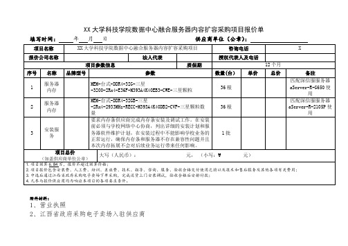
XX大学科技学院数据中心融合服务器内容扩容采购项目报价单(2024年)
填写时间:年月日供应商单位(公章):
项目名称
XX大学科技学院数据中心融合服务器内容扩容采购项目
咨询电话
X
报价公司名称
法人代表
授权代表人及电话
项目参数信息
质保期
12个月
序号
名称
品牌型号参数数来自(台)单价总价
备注
1
服务器内存
MEM-台式-DDR4-32G-三星-3200-2Rx4-E36F-M393A4K40EB3-CWE-三星颗粒
36根
匹配深信服服务器aServer-R-G650使用
2
服务器内存
MEM-台式-DDR4-32GB-三星-2Rx4-2933MHz-RECC-M393A4K40DB2-CVF-三星颗粒数量
36根
匹配深信服服务器aServer-R-2105P使用
3
安装服务
要求内存条供应商完成内存条安装及调试工作。在安装前必须与学校网络中心协商,列出详细的安装计划和服务器软件维护计划,在安装过程中不能影响学校业务的正常运行,确保内存条和服务器不存在兼容性问题并且本次内存拓展不会对后续业务运行带来任何影响。
1批
项目总价
(加盖供应商单位公章)
大写(人民币): 元,(小写:¥元)
1.项目预算6.84万,报价不超过预算价格;
2.项目报价包含安装费、人工费、培训、差旅费、技术、指导、咨询、服务、验收合格交付使用之前以及技术和售后服务及其他各项有关费用;
3.中选后通过江西省政府采购电子卖场下单采购,完成送货上门安装调试,验收合格后安排付款;
4.凡参与报价供应商均为响应本项目的各项要求条件。
附件材料:
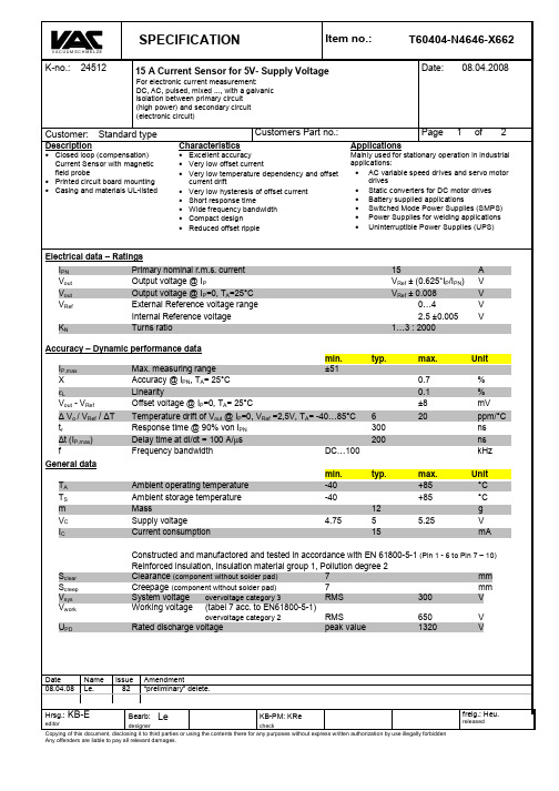
VAC 4646-X662 电流传感器 手册
Customer:
Description
Standard type
Characteristics
Customers Part no.:
Applications
• Excellent accuracy • Very low offset current • Very low temperature dependency and offset current drift • Very low hysteresis of offset current • Short response time • Wide frequency bandwidth • Compact design • Reduced offset ripple
DC = Date Code F = Factory
Schematic diagram
680 int REF 7 Ip 1...3 + RM 10k +
OUT
10
VC
V ref IN / OUT
40k
10k
8
Vout
40k 9 GND
4...6
Possibilities of wiring
primary windings NP
Customer:
Standard type
6 7 4
Customers Part no.:
General tolerances DIN ISO 2768-c
Toleranz der Stiftabstände ±0,2 mm (Tolerances grid distance)
Page
2
of
2
Mechanical outline (mm):
C150-E211-01EN fi-4640S 图像扫描器清洁与维护指南说明书

iRevisions, DisclaimersRevisionsFCC declaration: This equipment has been tested and found to comply with the limits for a Class B digital device, pursuant to Part 15 of the FCC Rules.These limits are designed to provide reasonable protection against harmful interference in a residential installation. This equipment generates, uses, and can radiate radio frequency energy and, if not installed and used in accordance with the instruction manual, may cause harmful interference to radio communi-cations. However, there is no guarantee that interference will not occur in aparticular installation. If this equipment does cause harmful interference to radio or television reception, which can be determined by turning the equipment off and on, the user is encouraged to try to correct the interference by one or more of the following measures:•Reorient or relocate the receiving antenna.•Increase the separation between the equipment and receiver.•Connect the equipment into an outlet on a circuit different from that to which the receiver is connected.•Consult the dealer or an experienced radio/TV technician for help.FCC warning: Changes or modifications not expressly approved by the party responsible for compliance could void the user's authority to operate the equipment.prohibited. The length of the parallel interface cable must be 3 meters (10feet) or less. The length of the serial interface cable must be 15 meters (50feet) or less.•The length of the power cord must be 3 meters (10 feet) or less.This Class B digital apparatus complies with Canadian ICES-003.Cet appareil numérique de la classe B est conforme à la norme NMB-003 duCanada.High Safety Required Use: The Product is designed, developed and manufac-tured as contemplated foe general use, including without limitation, generaloffice use, personal use and household use, but is not designed, developed andmanufactured as contemplated for use accompanying fatal risks or dangersthat, unless extremely high safety is secured, could lead directly to death,personal injury, severe physical damage or other loss (hereinafter "High SafetyRequired Use"), including without limitation, nuclear power core control, airplanecontrol, air traffic control, mass transport operation control, life support, weaponlaunching control. The Customer shall not use the Product without securing thesufficient safety required for the High Safety Required Use. In addition, Fujitsu(or other affiliate's name) shall not be liable against the Customer and/or anythird party for any claims or damages arising in connection with the High SafetyRequired Use by the Customer of the Product.As an E NERGY S TAR® Partner, Fujitsu Limited declares that this scanner meetsthe E NERGY S TAR® guidelines for energy efficiency. E NERGY S TAR ® is a U. S.registered mark.ChangesThe contents of this manual may be revised without prior notice.FUJITSU reserves the right to make changes to any products herein, to im-prove reliability, function, or design, without further notice and without obliga-tion.CopyrightsAll Rights Reserved, Copyright © 2001, FUJITSU LIMITED.Printed in Japan.No part of this manual may be reproduced in any form without permission.iiFujitsu OfficesPlease send your comments on this manual or on Fujitsu products to thefollowing addresses:FUJITSU COMPUTER PRODUCTS OF AMERICA,INC.2904 Orchard Parkway,San Jose. California 95134-2022,U.S.A.TEL:1-408-432-6333FAX:1-408-432-3908/FUJITSU AUSTRALIA LIMITEDFujitsu Hause 2 Julius Avenue North Ryde N.S.W 2113 AUSTRALIATEL:61-2-9776-4555FAX:61-2-9776-4019.au/FUJITSU CANADA,INC.2800 Matheson Blvd.East,Mississauga. Ontario L4W 4X5,CANADATEL:1-905-602-5454FAX:1-905-602-5457http://www.fujitsu.ca/FUJITSU DEUTSCHLAND GmbH. Frankfurter Ring 211,8000 München 40,F.R,GERMANYTEL:49-89-32378-0FAX:49-89-32378-100http://www.fujitsu.de/FUJITSU ESPAÑA,S.AEdificio torre Europa 5aPaseo de la Castellana 95Madrid 28046,SPAINTEL:34-1-581-8000FAX:34-1-581-8300/home/ FUJITSU EUROPE LTD.2,Longwalk Road,Stockey Park,Uxbridge Middlesex,UB11 1AB,U.KTEL:44-81-573-4444FAX:44-81-573-2643/home FUJITSU FRANCE S.A.I, Place des Etats-Unis, SILIC 310,94588 Rungis cedex, FRANCETEL:33-1-4180-3880FAX:33-1-4180-3866/home/FUJITSU COMPUTERS (SINGAPORE) PTE, LTD.20 Science Park Road #03-01, Tele Teck Park Singapore Science Park II, Singapore 117674 Republic of SingaporeTEL:65-777-6577FAX:65-771-5669.sg/FUJITSU HONG KONG Limited10/F, Lincoln House, Taikoo Place,979 King’s Road, Island East, Hong KongTEL:852-827-5780FAX:852-827-4724TLX:62667/FUJITSU ITALIA S.p.A.Via Nazario Sauro, 3820099 Sestos, Giovanni (MI), ITALYTEL:39-2-26294-1FAX:39-2-26294-201/homeFUJITSU NORDIC ABKung Hans väg,S-192 68 Sollentuna, SWEDEN TEL:46-8-626-4500FAX:46-8-626-4588/homeFUJITSU LIMITEDInternational OperationsMarunouchi 1-6-1, Chiyoda-ku,Tokyo 100 JAPANTEL:(81-3)3216-3211FAX:(81-3)3213-7174TLX:J2283Cable:”FUJITSU LIMITED TOKYO”http://www.fujitsu.co.jp/iiiNote, LiabilityREAD ALL OF THIS MANUAL CAREFULLY BEFORE USING THIS PROD-UCT.IF NOT USED CORRECTLY,UNEXPECTED INJURY MAY BECAUSED TO USERS OR BYSTANDERS.While all efforts have been made to ensure the accuracy of all information inthis manual, FUJITSU assumes no liability to any party for any damage causedby errors or omissions or by statements of any kind in this manual, its updatesor supplements, whether such errors are omissions or statements resulting fromnegligence, accidents, or any other cause. FUJITSU further assumes noliability arising from the application or use of any product or system describedherein; nor any liability for incidental or consequential damages arising from theuse of this manual. FUJITSU disclaims all warranties regarding the informationcontained herein, whether expressed, implied, or statutory.ivPrefaceThis manual explains how to clean and maintain the fi-4640S image scanner.The fi-4640S is a very fast and highly functional image scanner developed forhigh quality image processing, using charge-coupled device (CCD) imagesensors. This scanner features high speed simplex scanning with an automaticdocument feeder (ADF).Refer to the Operator’s Guide for basic information about the fi-4640S.vConventionsImportant information that requires special attention is indicated as follows:WARNINGWARNING indicates that serious personal injury may result if you do not followa procedure correctly.CAUTIONCAUTION indicates that minor personal injury, loss of data, or damage to thescanner may result if you do not follow a procedure correctly.Official Fujitsu part names are indicated with an initial capital letter, as in thepart name “Pick roller”.viviiCONTENTSCHAPTER 1DESCRIPTION ...............................................................1-1Units ...............................................................................1-2Assemblies.....................................................................1-4Operator Panel................................................................1-5Panel Display..................................................................1-6DESCRIPTIONCLEANINGREPLACEMENT OFPARTSTROUBLESHOOTINGD E S C R I C L E A N I N G R E P L A C E M E N T O F P A R T ST R O U B L E S H O O T I N GDESCRIPTIONThis chapter describes units, assemblies, indicators and LED functions.UnitsAssembliesOperator PanelPanel DisplayUnits6 ADF paper chute3ADF lever2ADF 1 Stacker5Document bed8Oparator panel4Option board slot 9Interfaceconnector10Power inlet 12EXTconnector 11Power switch13D E S C R I P T IAssembliesThumb screwStackerPick roller 2I IOperator panelThe Operator panel is located on the upper right hand side of the scanner.The panel consists of an LCD (16characters x 2 lines), LEDs, and buttons.ArrangementPanel DisplayButton/LED FunctionD E S C R I P T ICounter Display The scanner is provided with acounter display.When the counter value is 0, no number is displayed.Panel DisplayOperation statusThe operation status is indicated by the following messages:<Power-on><Reading><Low Power Mode>When the Scanner Display turns Off and the powerremains “On”, the scanner is in the Low Power Mode.One of the following will wake up the scanner:•Pressing any button.•Setting the paper on the ADF.•Sending a command from the host computer.<Waiting for Start>The scanner displays the following screen when waiting for theStart button to be pressed:(Only When the Video InterfaceOption is installed.)<Cleaning request>When the Pick roller cleaning is necessary, the scanner displaysthe following on the upper line:When the ADF glass cleaning is necessary, the scanner displaysthe following on the LCD:Clean the Pick roller or the ADF glass in accordance with theinstructions given in chapter 2, Cleaning the ADF, and chapter 3,Pick Roller.D E S C I I Temporary error<Hopper empty>This message is displayed if there is no more paper on the ADF paper chute during a read operation in ADF mode. Fill the ADF paper chute with paper. To enable the read operation, press the stop button.<Jam>This message is displayed if a document is jammed in the ADF.See Chapter 4 for removing jammed ducuments.<ADF cover open>This message is displayed if the ADF is not closed completely.Close the ADF completely, and enable the read operation.<Double feed error>This message is displayed when the ADF detects a Double feed error. Check the document and re-scan it.AlarmOne of the following messages is displayed if an error occurs in the scanner. If one of the following error messages is displayed, turn the power Off and then On again. If the same message is displayed, contact your service representative.<Optical alarm><FB mechanism alarm>When the total number of sheets scanned by the ADF is less than 100, the message above and the message below are displayed alternately. Remove the bracket (Shipping Lock) that holds the carrier in place.<Motor fuse alarm><Lamp fuse alarm><Image transfer alarm>(only when SCSI is used)<Memory alarm>D E S C R I P T I <EEPROM alarm><FAN alarm><IPC board alarm>When this message is displayed, turn Off system power and then turn it On again. Alternatively,replace the current cable with one recommended by the manufacturer of the SCSI board. When the cause of the alarm has been corrected, the scanner automatically resumes operation once power is turned On again.CLEANINGThis chapter describes cleaning supplies, areas that require clean-ing, and procedures for cleaning the ADF and the flatbed.Cleaning Supplies and Areas RequiringCleaningCleaning the ADFCleaning the Flatbed2-12-2Cleaning Supplies and Areas Requiring CleaningFor more information on cleaning supplies, contact your dealer.*1If the display on the operator panel shows “Please clean Pick-roller”, then clean it regardless of the frequencies recommended here.*2CAUTIONDo not clean the rubber rollers with cleaner F2.*3Refer to the Abrasion counter on the Operator panel to estimate when the next cleaning is necessary.When the following paper types are used, it may be necessary to clean more frequently:• Paper with a smooth surface, such as coated paper.• Paper almost entirely covered with printing.• Paper with special chemical coatings, such as carbonless paper.• Paper including a great quantity of calcium.• When reading a great many documents written with a pencil.C L E A N I NG2-4Cleaning the ADF1Pull the ADF lever to open the ADF.2Lightly spray a new piece of cleaning paper with cleaner F1.3Place the cleaning paper onshort side touches the Plastic roller.4Close the ADF and turn the power on to start the cleaning.5After making sure the cleaning stops, turn the power off.6Turn the cleaning paperupside down, repeat steps 1through 5.Cleaning paperCleaning paperPlastic rollersC L E A N I NGGlassCleaning the ADF with a Dry cloth or a Cloth with Cleaner F11Pull the ADF lever to open the ADF.2Use a dry cloth or a clothmoistened with Cleaner F1 to softly remove dirt and dust as follows.Pad assembly :Wipe the pad in a downwarddirection (as indicated by the arrow).Be careful not to catch the spring for the Pick roller when wiping.Glass:Wipe the glass lightly.NOTEIf the glass is dirty, the image may include black vertical stripes.Pick roller:Wipe the roller.Be careful not to damage the surface of the roller and the mylar strip above the Pick roller.Feed rollers :and Plastic rollersWipe the rollers.Be careful not to damage the surface of the rollers.Pick roller2-6C L E A N I N GSheet guide (white part)Sheet guide (white part):Wipe the sheet guide.NOTEIf the Sheet guide is dirty, the front image may show vertical stripes.3Close the ADF to lock the ADF lever.CAUTIONDon’t wipe the pad rubbers with the F2 cleaner.2-8Cleaning the Pick Arm Rollers1Pull the ADF lever to open the ADF.2Moisten a cotton swab or Dry cloth with F1 or F2 Cleaner.3Wipe the small Plastic rollers at the tip of the Pick Arm.4Wipe the small Plastic rollers and the Pick Arm with a clean,dry cloth to dry them.NOTEF2 to remove the contamination.CAUTIONDon’t wipe the pad rubbers with the F2 cleaner.C L E A N I NGCleaning the Plastic rollers with Cleaner F21Pull the ADF lever to open the ADF.2Moisten a cotton swab with Cleaner F2.3Wipe the Plastic roller surfaces.CAUTIONDon’t wipe the Pick Rollers with a cotton swab using cleaner F2.4Wipe the Plastic roller surface with a clean, dry cloth. Allow itto dry.2-10Cleaning the FlatbedCleaning the Flatbed with a Cloth and Cleaner F1However, do not use organic solvents like thinner.1Open the Document cover.2Apply Cleaner F1 to a clean cloth.3Wipe the Document holding pad and the Document bed.4Allow them to dry.NOTEBe sure to prevent liquid from seeping through the opening between the Document bed and the plastic cover.REPLACEMENT OF PARTSThis chapter describes how to replace the pad assembly and thepick roller.Pad AssemblyPick RollerPad AssemblyNOTE100,000 sheets or one year. Use the Abrasion counter on the Operator panel to estimate when the Pad assembly needs replacement. The life span may be decreased by as much as halfwhen carbonless paper is read frequently.WARNINGTurn off the power before replacing the Pad Assembly.1Pull the ADF lever to open the ADF.2Push the Pick Arm carefully.Pad assemblyPick RollerNOTEUse the Abrasion counter on the operator panel to estimate when the Pick roller needs replacement.The life span may be decreased by as much as half when carbonless sheets are frequently read.WARNINGTurn off the power before replacing the Pick Rollers.1Pull the ADF lever to open the ADF.2Remove the two Thumbscrews.Use a Phillips screwdriver if they are tight.R E P L A C E M E N T O F P A R T SPosition for ReplacementPick roller 1Pick roller 2Stopper3With both hands, lift up Guide A and disengage its tip from the right hole. Then lift the right side of the cover and remove it.4To remove the Pick rollers,turn the stopper counter-clockwise.5To remove the Pick roller 1,move it to the left and then liftit.6Immediately after removing the Pick roller 1, remove the Pickroller 2 in the same way.R E P L A C E M E N T O F P A R TS7To attach the new Pick rollers,place Pick roller 1 from the right side above the bearing forPick roller 1.Put the shaft of Pick roller 1into the bearing. Then, slideside.8Attach Pick roller 2, in thesame way as Pick roller 1 asshown in step 7.Then slide the Pick roller 2toward right side.R E P L A C E M E N T O F P A R T SOperating Position9Turn the stopper clockwise to secure the Pick rollers.Thumb screws10Attach Guide A in the reverse sequence of step 3 and align the screw hole. See the graphic on page 1-4.11Tighten the thumb screws.12Close the ADF unit.TROUBLESHOOTINGThis chapter describes how to clear paper jams and run initialchecks. It also contains a Problem Checklist that should be com-pleted before you call a service representative.Clearing Paper JamsInitial ChecksProblem ChecklistClearing Paper Jams1Remove all the documents from the ADF paper chute.2Pull the ADF lever to open the ADF.3Remove the jammed document(s).All staples and paper clips should be removed from all documents bofore scanning.-Be careful not to pull the spring for the Pad while removing a jammed document.4Close the ADF so that the ADFlever locks.T R O U B L E S H O O T I N GInitial ChecksIf a problem occurs, check the following items before contacting the manufacturer’s authorized service center.T R O U B L E S H O O T I N GT R O U B L E S H O O T I N GT R O U B L E S H O O T I N G。
摩克斯 V464 系列芯片计算机产品介绍说明书

The V464 embedded computers are based on the AMD x86 processor, and feature 4 serial ports, quad LAN ports, 4 USB 2.0 hosts, and CompactFlash. A VGA interface is also included, making the V464 computers particularly well-suited for industrial applications such as SCADA and factory automation.The V464 computers’ 4 serial ports can be used to connect a wide range of serial devices, and the quad 10/100 Mbps Ethernet ports offer a reliable solution for network redundancy, promising continuousFront Viewoperation for data communication and management. In addition, the CompactFlash and USB sockets provide the V464 computers with the reliability needed for industrial applications that require data buffering and storage expansion.The V464 computers come with the WinCE 6.0 or WinXP Embedded operating system already installed. WinCE 6.0 and WinXP Embedded provide programmers with a friendly environment for developingsophisticated, bug-free application software at a lower cost.OverviewAppearanceRear View10/100 Mbps SocketSerial Ports x 2Serial Ports x 2 9-36 VDCComputerCPU:******************************************,500 MHzOS (pre-installed): Windows CE 6.0 or Windows XP Embedded System Chipset: AMD CS5536BIOS: 4 Mbit Flash BIOS, supporting Plug & Play, APM 1.2, ACPI 1.0 SRAM: 256 KB, battery backupFSB: 400 MHzSystem Memory: 200-pin SO-DIMM socket with built-in 256 MB (CE) or 512 MB (XPe) DDR, supporting DDR400 up to 1 GB Expansion Bus: PC/104-Plus onboardUSB: USB 2.0 compliant hosts x 4, type A connector, supports system boot upStorageBuilt-in: 256 MB (CE) or 1 GB (XPe) industrial DOM for OS Storage Expansion: CompactFlash socketOther PeripheralsKB/MS: 1 PS/2 interface supporting standard PS/2 keyboard and mouse through Y-type cableAudio: AC97 audio, with line-out interfaceDisplayGraphics Controller: CPU integrated 2D graphicsDisplay Interface: CRT interface for VGA outputEthernet InterfaceLAN: 4 10/100 Mbps, auto-sensing (RJ45) portsController: Realtek RTL8100CLMagnetic Isolation Protection: 1.5 KV built-inSerial InterfaceSerial Standards:• 2 RS-232 ports (DB9 male)• 2 RS-232/422/485 ports, software selectable (DB9 male)ESD Protection: 15 KV for all signalsSerial Communication ParametersData Bits: 5, 6, 7, 8Stop Bits: 1, 1.5, 2Parity: None, Even, Odd, Space, MarkFlow Control: RTS/CTS, XON/XOFF, ADDC® (automatic data direction control) for RS-485Baudrate: 50 bps to 921.6 Kbps (non-standard baudrates supported; see user’s manual for details)Serial SignalsRS-232: TxD, RxD, DTR, DSR, RTS, CTS, DCD, GNDRS-422: TxD+, TxD-, RxD+, RxD-, GND RS-485-4w: TxD+, TxD-, RxD+, RxD-, GNDRS-485-2w: Data+, Data-, GNDLEDsSystem: Power, Battery, StorageLAN: 10M/Link x 2, 100M/Link x 2 (on connector)Switches and ButtonsPower Switch: on/offReset Button: For warm rebootPhysical CharacteristicsHousing: AluminumWeight: 1.32 kgDimensions:Without ears: 223 x 121 x 57 mm (8.78 x 4.76 x 2.24 in)With ears: 248 x 140 x 70 mm (9.76 x 5.51 x 2.76 in)Mounting: DIN-Rail, wallEnvironmental LimitsOperating Temperature: -10 to 60°C (14 to 140°F)Operating Humidity: 5 to 95% RHStorage Temperature: -20 to 80°C (-4 to 176°F)Anti-vibration: 5 g rms @ IEC-68-2-34, random wave, 5-500 Hz, 1 hr per axisAnti-shock: 50 g @ IEC-68-2-27, half sine wave, 11 msPower RequirementsInput Voltage: 9 to 36 VDC (3-pin terminal block for V+, V-, SG) Power Consumption: 26 W• 730 mA @ 36 VDC• 1080 mA @ 24 VDC• 2820 mA @ 9 VDCRegulatory ApprovalsEMC: CE (EN55022 Class A, EN61000-3-2 Class A, EN61000-3-3, EN55024), FCC (Part 15 Subpart B, CISPR 22 Class A), CCC (GB9254, GB 17625.1)Safety: UL/cUL (UL60950-1, CSA C22.2 No. 60950-1-03), LVD, CCC (GB4943)Green Product: RoHS, cRoHS, WEEEReliabilityAlert Tools: Built-in buzzer and RTC (real-time clock) with battery backupAutomatic Reboot Trigger: Built-in WDT (watchdog timer) supporting 1-255 level time interval system reset, software programmable WarrantyWarranty Period: 3 yearsDetails: See /warrantyHardware SpecificationsWindows Embedded CE 6.0System Utilities: Windows command shell, telnet, ftpFile System: FAT (on-board flash)Protocol Stack: TCP, UDP, IPv4, SNMP V2, ICMP, IGMP, ARP, HTTP, CHAP, PAP, SSL, DHCP, SNTP, SMTP, Telnet, FTP, PPP Telnet Server: Allows remote administration through a standard telnet client.FTP Server: Used for transferring files to and from remote computer systems over a network.File Server: Enables clients to access files and other resources over the network (Microsoft® Wincows® CE).Web Server (httpd): Includes ASP, ISAPI Secure Socket Layer support, SSL 2, SSL 3, and Transport Layer Security (TLS/SSL 3.1) public key-based protocols, and Web Administration ISAPI Extensions.Dial-up Networking Service: RAS client API and PPP, supporting Extensible Authentication Protocol (EAP) and RAS scripting. Watchdog Service: CPU Hardware function to reset CPU in a user specified time interval (triggered by calling a MOXA library function).Application Development Software:• Moxa WinCE 6.0 SDK• C Libraries and Run-times• Component Services (COM and DCOM)• Microsoft® .NET Compact Framework 2.0 SP2• XML, including DOM, XQL, XPATH, XSLT, SAX, SAX2• SOAP Toolkit Client• Winsock 2.2Software SpecificationsWindows XP EmbeddedSystem Utilities: Windows command shell, Telnet, ftp, Wireless Zero Configuration File System: NTFSProtocol Stack: DHCP, IPv4, DNS, IPsec, HTTP, TCP, UDP, ICMP, IGMP, ARP, TAPI, TSP, SNMP V2, NTP, ICS, PPP, CHAP, EAP, SNTP, Telnet, SNTP, FTP, SMTP, PPPoE, PPTP, NetBIOSTelnet Server: Allows users to connect to Telnet servers from remote computers.IIS Web Server: Allows you to create and manage Web sites.Terminal Server: Microsoft Terminal Server client application (mstsc.exe).COM+ Services: The next evolution of Microsoft Component Object Model (COM) and Microsoft Transaction Server (MTS).Computer Browser Service: Computer browsing functionalityexposed by Windows through Microsoft Networking. Allows a client machine to browse its network neighborhood for available computers exposing file and print sharing services.Disk Management Services: Support for disk and volumemanagement operations. The component implements a Component Object Model (COM) interface that can be used to query and configure disks and volumes, both basic and dynamic. The component also monitors disk arrivals and removals and other changes in the storage subsystem.Remote Registry Service: Enables remote users to modify registry settings on this computer.Application Development Software:• Microsoft .Net Framework 2.0 with service pack 2 (CLR and the .NET Framework class library)• Active Directory Service Interface (ADSI) Core • Active Template Library (ATL), 2.0• Certificate Request Client & Certificate Autoenrollment (CLR and the .NET Framework class library) • COM APIs• Common Control Libraries • Common File Dialogs• Direct3D, DirectPlay, DirectShow and Direct show filters • Distributed Transaction Coordinator (MSDTC)• Enhanced Write Filter (Redirect disk write operations to volatile (RAM) or non-volatile (disk) storage) • Event Log, Internet Explorer • Mapi32 Libraries• Message Queuing (MSMQ) Core• Microsoft Visual C++ Run Time Libraries • Power Management dynamic-link library • Registry Editor • RPC• Smart Card Cryptographic Service Providers• USB 2.0 core drivers compliant with The USB .95 or 1.0 • Windows API, Media Player 10, Script Engines, and WMIV464 computer• Ethernet cable: RJ45 to RJ45 cross-over • cable, 100 cmDIN-rail Mounting Kit• PS2 to KB/MS Y-type Cable• Document and Software CD or DVD • Quick Installation Guide (printed)• Product Warranty Statement (printed)• Package ChecklistAvailable ModelsV464-CE: x86 embedded computer with 4 serial ports, quad LANs, VGA, CompactFlash, USB, and WinCE 6.0 OSV464-XPE: x86 embedded computer with 4 serial ports, quad LANs, VGA, CompactFlash, USB, and Windows XP Embedded OSOptional Accessories (can be purchased separately)PWR-24250-DT-S1: Power adaptorPWC-C7US-2B-183: Power cord with 2-pin connector, USA plug PWC-C7EU-2B-183: Power cord with 2-pin connector, Euro plug PWC-C7UK-2B-183: Power cord with 2-pin connector, British plug PWC-C7AU-2B-183: Power cord with 2-pin connector, Australia plug PWC-C7CN-2B-183: Power cord with 2-pin connector, China plugOrdering Information。
NEC X464UNS-2 超窄边框公共显示屏说明书

SpecificationsMultiSync, NaViSet, TileMatrix and Frame Comp are trademarks or registered trademarks of NEC Display Solutions, Ltd. in Japan, the United States and other countries.The terms HDMI and HDMI High-De nition Multimedia Interface, and the HDMI Logo are trademarks or registered trademarks of HDMI Licensing LLC in the United States and other countries.DisplayPort and DisplayPort Compliance Logo are trademarks owned by the Video Electronics Standards Association in the United States and other countries.HDBaseT™ and the HDBaseT Alliance logo are trademarks of the HDBaseT Alliance.CRESTRON and CRESTRON ROOMVIEW are trademarks or registered trademarks of Crestron Electronics, Inc.AMX is a trademark or registered trademark of AMX in the United States and other countries.Trademark PJLink is a trademark applied for trademark rights in Japan, the United States and other countries and areas.VESA is a trademark of a nonpro t organization, Video Electronics Standard Association.All other trademarks are the property of their respective owners. The images in this brochure are samples.All speci cations are subject to change without notice. September 2016LCD MODULECONNECTIVITYPOWERPHYSICAL SPECIFICATIONSViewable Size (Diagonal )Active Screen Area (W × H)Panel Technology Native ResolutionBrightness (Factory setting /Maximum)Contrast Ratio (Typical)Viewing Angle [°]Response Time (Typical)Backlight Input TerminalsOutput Terminals External Control Service Port Option Slots Speaker Output Power RequirementPower Consumption (Typical)Power Consumption -standby Mode Bezel WidthDisplayPort HDMI DVI VGA AudioDisplayPort AudioExternal SpeakersRS232C in Ethernet Remote inExpansion Slots External SpeakersSVA1,920 × 1,080500/700 cd/m178 horizontal /178 vertical (at CR>10)8 ms (G to G)Direct LED backlight DisplayPort × 1HDMI × 1DVI-D × 1Mini D-sub 15pin × 1Digital: HDMI × 1, DisplayPort × 1, Analogue: 3.5 mm Stereo Mini Jack × 2DisplayPort × 13.5 mm Stereo Mini Jack × 1Speaker terminals for L /R × 1D-Sub 9 pin × 1RJ-45 10/100BASE-T × 2 (In/out)3.5 mm Stereo Mini Jack × 1USB Type A × 1Open pluggable speci cation (NEC /Intel OPS standard) × 1, Interface extension × 115 W + 15 W (8 Ω)<0.5 W2.3 mm (Left / Top), 1.2 mm (Right / Bottom)46"/ 1,168 mm 1,018.1 × 572.7 mm3,500:1 (Native contrast)3.0 A to 1.2 A @ 100 V to 240 V AC,50/60 Hz120 W @ defaultMODEL X464UNS-2N8000-8866Ambient Light / IR Remote23Frame Comp FunctionBy synchronizing the content across the wall, this feature supports a seamless appearance and displays uninter-rupted content to create one stunning image over allscreens.The dual slot technology allows for the integration of Open Pluggable Speci cation (OPS*) boards and other option slot products without the need to store additional external equipment. This offers the greater exibility customers require.NaViSet Administrator 2This software is an all-in-one remote supportsolution that runs from a central location and provides monitoring, asset management and control functionality of the majority of NEC display devicesand Windows computers. It is ideal for multi-device installations over larger infrastructures.Dedicated Colour Calibration SoftwareAs the brightness and colour temperature of the LCD change with time, colours may not match across multiple screens. Our dedicated colour calibration software* ensures colour uniformity and delity across mul-tiple screens, creating a perfectly matched image in tiled environments.* NEC Display Wall CalibratorProof of PlayThis function provides accurate proof that displays are working as established and is helpful when checking on the status of the displays installed at a user’s site.Advanced Heat ManagementMonitoring and managing the temperature of each displayis crucial to secure reliability and longevity.DisplayPort Multi-stream FunctionThanks to the multi-stream function of DisplayPort technology, multiple displays can be daisy chained and still be individually controlled. This also makes a 2 × 2video wall with native Ultra High De nition 4K /2K (3,840 × 2,160) possible.Without heat management, displays placed higher on a wall sustain more heat. However, NEC’s advanced heat management ensures uniform heat dissipation.Auto TileMatrix and Auto ID TechnologyAuto TileMatrix and ID features allow you to simply set up the size of the video wall on the rst display, and then automatically scale the content through the remaining displays to set up the entire video wall (of up to 100 displays in a 10 × 10 matrix).Intelligent Wireless Data FunctionThe built-in near eld communication (NFC) chip allows data to be read and written via a mobile phone or tablet PC. Users can signi cantly reduce installation costs as displays can be easily con gured and serviced using the NEC NFC Android app. This is available even when the display is switched off and is especially useful on larger installations.This optional human (motion) sensor accessory (KT -RC2) helps to deliver creative digital signage to end users by allowing for dynamic control of brightness, audio and source inputs while saving operating costs. Auto dimming adjusts the backlight of the LCD automaticallydepending on the amount of ambient light.X464UNS-2• Just one cable each for video and control • Only two cables required for setup• Up to 100 displays can be daisy chainedWith FRAME COMP*Without FRAME COMP* Only available through NEC.*OPS is a standard established by Intel Corporation.OPS*Interface Extension No human (motion) detectedHuman (motion) detectedOther Useful Features and Functions•Landscape /portrait capability •Scheduler w/real-time clock•Intelligent power management system•Power-on delay •Screen saver function •Aspect ratio control •Memo function •Carbon footprint meter•Image and on-screen display ip •Picture-in-picture, Picture-out-picture •Point zoom•Control lock function•6-axis colour adjustments and sRGB standard•Advanced video settings(noise reduction, adaptive contrast)•Colour temperature adjustment•Programmable gamma setting (3 settings)•DICOM simulation•Plug and play (DDC/CI, DDC2B)•HDCP (High-bandwidth Digital Content Protection)•Ethernet and RS-232C control and communication •CRESTRON ROOMVIEW ™•AMX Discovery HTTP server•PJLink •Self-diagnosis •Status log function •Firmware update over LAN•Metal rear cabinet with VESAStandard (FDMIv1) mounting interface •HandlesAC INMain Power SwitchService portAUDIO IN 1, 2DVI IN (DVI-D)EXTERNAL SPEAKERTERMINALSAUDIO OUTLAN ports (RJ-45)REMOTE INDisplayPort connectorsRS-232C (D-Sub 9 pin)VGA IN(mini D-Sub 15 pin)HDMI INTerminalsX464UNS-2。
Tektronix P6015A 1000X高压探头说明书

P6015A1000X High Voltage Probe 070-8223-04SpecificationsWarranted CharacteristicsThis section lists the various warranted characteristics that describethe P6015A High V oltage Probe. Included are warranted electricaland environmental characteristics.Warranted characteristics are described in terms of quantifiableperformance limits which are warranted.The electrical characteristics listed in Table 1–3 apply under thefollowing conditions:H The probe and instrument with which it is used must have beencalibrated at an ambient temperature of between +20 °C and+30 °C.H The probe and instrument must be in an environment whoselimits are described in Table 1-3.H The probe and instrument must have had a warm-up period of atleast 20 minutes before applying elevated voltages.P6015A Instruction Manual1–23Specifications1–24P6015A Instruction ManualTable 1–3: Warranted Electrical CharacteristicsCharacteristic InformationMaximum input voltageDC + peak AC 11.5 kV to 20 kV. See frequency derating curve in Figure 1–4. (DC plus peak AC rating is limited to temperatures below 35°C.)Peak pulse40 kV a (Never exceed 20 kV rms)Duty cycle derating – 100 ms maximum duration at 10%maximum duty cycle. See duration and duty cycle derating curve in Figure 1–5.Altitude derating – Peak pulse derated linearly from 40kV at 8000feet (2440m) to 30kV at 15,000feet (4570m) altitude.Relative Humidity (RH) derating – Voltage derated with increasing temperature and relative humidity (see Figure 1–7).Bandwidth (–3 dB)Test conditions: Test oscilloscope bandwidth must be ≥100 MHz, Z source = 25 W 10-ft cable 75 MHz 25-ft cable25 MHzRise Time 210-ft cable ≤4.67 ns (calculated from bandwidth)25-ft cable≤14 ns (calculated from bandwidth)DC attenuation1000:1 ±3% (Excluding oscilloscope error)Test conditions: Oscillo-scope input resistance must be 1 M W ±2%1 Characteristic not checked in manual 2T r (ns) = .35/BW (MHz)SpecificationsP6015A Instruction Manual1–25Table 1–4: Warranted Environmental CharacteristicsCharacteristic InformationTemperatureNonoperating –55_C to +75_C (–67_F to +167_F)OperatingDC + peak AC Peak Pulse0_C to +35_C (+32_F to +95_F)0_C to +50_C (+32_F to +122_F)(See Table 1–1 on page 1–10 and Time Limitations Specification below)HumidityNonoperating / Operating 95% relative humidity at +50°C (+122°F). See Figure 1–7 for derating characteristics.Maximum altitudeNonoperating 15,000 m (50,000 ft)Operating4,600 m (15,000 ft)Peak pulse voltage derated from 40kV at 8000 feet (2440m) to 30kV at 15,000 feet (4570m).Vibration (random)Nonoperating 3.48g rms from 5 to 500Hz. Ten minutes on each axis.Operating 2.66g rms from 5 to 500Hz. Ten minutes on each axis.Shock (nonoperating)500 g, half sine, 0.5 ms duration, 18 shocks total in three axis.Time LimitationsLess than 70% of Rated Input Voltage at 0–35_C No time limit Greater than 70% of Rated Input Voltage at 0–35_C 30 minutes maximum in any 2.5 hour period 35–50_C15 minutes maximum in any 2.5 hour periodSpecifications1–26P6015A Instruction Manual0%30%70%80%95%25°C 35°C 50°C40kV 40kV40kV35kV 35kV20kV 25kV 35kVRelative HumidityFigure 1–7: Humidity Derating Chart10M1M 100k 10k 1k100M1001k10k 100k1M10M100M P r o b e I m p e d a n c e FrequencyP h a s e A n g l e0°–10°–20°–30°–40°–50°–60°–70°–80°–90°10Figure 1–8: Typical Input Impedance and PhaseSpecificationsP6015A Instruction Manual1–27Typical and Nominal CharacteristicsThis section lists the various typical and nominal characteristics that describe the P6015A High V oltage Probe.Nominal characteristics are determined by design and/or inspection.Nominal characteristics do not have tolerance limits.Typical characteristics are described in terms of typical or average performance. Typical characteristics are not warranted.Table 1–5: Typical Electrical CharacteristicsCharacteristic InformationInput resistance 100 M W ±2%. See Figure 1–8 for typical input impedance curve.Input capacitance ≤3 pF when probe is properly LF compensated. See Figure 1–8 for typical input impedance curve.LF compensation range 7 pF to 49 pFAberrations25% p-p for the first 200ns on a 100MHz oscilloscope when used with 10in (25.4cm) ground lead.<10% p-p typical after first 200ns; ±5% after the first 400ns.Temperature coefficient of DC attenuation0.006% per degree C 1Voltage coefficient of DC attenu-ation 0.018% per kV Delay time10ft cable: 14.7 ns 25ft cable: 33.3 ns1Resistor temperature rose 60_C at 20 kV rms over a 30 minute period.SpecificationsTable 1–6: Nominal Mechanical CharacteristicsCharacteristic InformationDiameter (probe body)8.9 cm (3.5 in) maximumLength (probe body)34.5 cm (13.6 in)Length (cable)10-ft cable 3.05 m (10 ft)25-ft cable7.62 m (25 ft)Compensation box 2.5 ×4.1 ×8.3 cm (1 ×1.6 ×3.25 in)Net weight (probe assembly)10-ft cable0.66 kg (1.47 lbs)25-ft cable0.75 kg (1.66 lbs)Shipping weight (includingaccessories)10-ft cable 2.85 kg (6.27 lbs)25-ft cable 2.93 kg (6.46 lbs)1–28P6015A Instruction Manual。
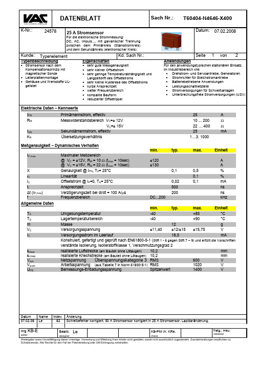
sensors_product_vac4646-x400

12,7
(Tolerances grid distance)
10
Type T60404-N4646-X661 and …X681 T60404-N4646-X662 and …X682 T60404-N4646-X663 and …X683 T60404-N4646-X664 and …X684
24
(1 … 3): U 2000
[kHz] DC to [%]
100 0,7 .
(1 … 3): U 2000
100 0,7 .
(1 … 3): U 2000
100 0,7 .
(1 … 3): U 1400
100 0,7 .
(1 … 3): 2000
U . 100
0,7 .
(1 … 3): 2000
U . 100
page 1 of 9
Type series of new VAC current sensors
Item no. Type T60404-N…
Dimensional diagrams
Encapsulated
Integrated Electronics
Secondary conn.
accuracy X @ IPN ; Tamb = 25 °C Primaryconnection
0,7 .
(1 … 3): 2000
U . 100
0,7 .
(1 … 3): 1400
U . 100
0,7 .
(1 … 5): I 1000
100 0,5 .
Pins
.. .1 .. .1 .. .1 .. .1 .. .2 .. .2 .. .2 .. .2 .. .3
4646-X400
DC = Date Code F= Factory
Anschlußschema
Ip 1...3 + RM 4...6 9 - VC M CA + 8 + VC 7 IS +
Beschaltungsmöglichkeiten für VC = ±15V
(Werte bei TA = 85°C, R M = 22Ω) Beschaltung
1,905
7 9
Z
4 6
1,74 11,43 1,29 (2,64) 12,7 F DC
Einzelheit Z
0,6
0,7
3 1
14,45
4646X400 F DC
7,6 21
3,5±0.5 0,65
3x 0,7x0,6
6x Ø1,0
DATENBLATT
V AC U UM SC H M ELZE
Sach Nr.:
T60404-N4646-X400
Datum: 07.02.2008
K-Nr.:
24578
25 A Stromsensor
Für die elektronische Strommessung: DC, AC, Impuls..., mit galvanischer Trennung zwischen dem Primärkreis (Starkstromkreis) und dem Sekundärkreis (elektronischer Kreis)
.
1 25 130 25 1:1000 0,12
> > >
1
3
.
2 10 65 20 2:1000 0,54
400V负载电压G3VM-401A D型号MOS FET传感器电器产品说明书

G3VM-401A/D MOS FET RelaysExpanded Range of Analog-switchingMOS FET Relays with 400-V LoadVoltage.•A 4-pin Relay now available in the 400-V load voltage se-ries.•Continuous load current of 120 mA.•Dielectric strength of 2,500 Vrms between I/O.RoHS compliant!■Application Examples•Measurement devices•Security systems•Amusement machinesNote:The actual product is marked differently from the imageshown here.■List of Models■DimensionsNote:All units are in millimeters unless otherwise indicated.■Terminal Arrangement/Internal Connections (Top View)■PCB Dimensions (Bottom View)Contact form Terminals Load voltage (peak value)Model Number per stick Number per tape SPST-NO PCB terminals400 VAC G3VM-401A100---Surface-mountingterminalsG3VM-401DG3VM-401D(TR)---1,500G3VM-401A G3VM-401DNote:The actual productis marked different-ly from the imageshown here.Note:The actual productis marked different-ly from the imageshown here.G3VM-401AG3VM-401AG3VM-401A/DG3VM-401A/D■Absolute Maximum Ratings (Ta = 25°C)■Electrical Characteristics (Ta = 25°C)■Recommended Operating ConditionsUse the G3VM under the following conditions so that the Relay will operate properly.■Engineering DataLoad Current vs. Ambient TemperatureG3VM-401A(D)■Safety PrecautionsRefer to “Common Precautions” for all G3VM models.ItemSymbol Rating Unit Measurement ConditionsInputLED forward currentI F 50mARepetitive peak LED forward currentI FP1A 100 µs pulses, 100 pps LED forward current reduction rate∆ I F /°C −0.5mA/°C Ta ≥ 25°CLED reverse voltage V R 5V Connection temperatureT j 125°C OutputOutput dielectric strength V OFF 400V Continuous load current I O 120mA ON current reduction rate ∆ I ON /°C −1.2mA/°C Ta ≥ 25°CConnection temperatureT j 125°C Dielectric strength between input and output (See note 1.)V I-O 2,500Vrms AC for 1 minOperating temperature T a −40 to +85°C With no icing or condensation Storage temperature T stg −55 to +125°C With no icing or condensation Soldering temperature (10 s)---260°C10sNote:1.The dielectric strength between the input andoutput was checked by applying voltage be-tween all pins as a group on the LED side and all pins as a group on the light-receiving side.ItemSymbol Mini-mum Typical Maxi-mum UnitMeasurement conditions InputLED forward voltage V F 1.0 1.15 1.3V I F = 10 mA Reverse currentI R ------10µA V R = 5 V Capacity between terminals C T ---30---pF V = 0, f = 1 MHz Trigger LED forward currentI FT ---13mA I O = 120 mA OutputMaximum resistance with output ON R ON ---1835ΩI F = 5 mA, I O = 120 mA Current leakage when the relay is openI LEAK ------ 1.0µA V OFF = 400 V Capacity between I/O terminals C I-O ---0.8---pF f = 1 MHz, Vs = 0 V Insulation resistance R I-O 1,000------M ΩV I-O = 500 VDC, RoH ≤ 60%Turn-ON time tON ------ 1.0ms I F = 5 mA, R L = 200 Ω, V DD = 20 V (See note 2.)Turn-OFF timetOFF------ 1.0ms Note:2.Turn-ON and Turn-OFFTimesItemSymbol MinimumTypicalMaximum UnitOutput dielectric strength V DD------320V Operating LED forward current I F 57.525mA Continuous load current I O ------100mA Operating temperatureT a− 20 ---65°CCommon Precautions!WARNINGBe sure to turn OFF the power when wiring the Relay, other-wise an electric shock may be received.!WARNINGDo not touch the charged terminals of the SSR, otherwise an electric shock may be received.!CautionDo not apply overvoltage or overcurrent to the I/O circuits of the SSR, otherwise the SSR may malfunction or burn.!CautionBe sure to wire and solder the Relay under the proper soldering conditions, otherwise the Relay in operation may generate ex-cessive heat and the Relay may burn.Typical Relay Driving Circuit ExamplesUse the following formula to obtain the LED current limiting resis-tance value to assure that the relay operates accurately.Use the following formula to obtain the LED forward voltage value to assure that the relay releases accurately.Protection from Surge Voltage on the Input TerminalsIf any reversed surge voltage is imposed on the input terminals, insert a diode in parallel to the input terminals as shown in the fol-lowing circuit diagram and do not impose a reversed voltage value of 3V or more.Surge Voltage Protection Circuit ExampleProtection from Spike Voltage on the Output TerminalsIf a spike voltage exceeding the absolute maximum rated value isgenerated between the output terminals, insert a C-R snubber or clamping diode in parallel to the load as shown in the following circuit diagram to limit the spike voltage.Spike Voltage Protection Circuit ExampleUnused Terminals (6-pin models only)Terminal 3 is connected to the internal circuit. Do not connect anything to terminal 3 externally.Pin Strength for Automatic Mountingn order to maintain the characteristics of the relay, the force imposed on any pin of the relay for automatic mounting must not exceed the following.In direction A: 1.96 NIn direction B: 1.96 NLoadTransistor10 to 100 kΩLoadR1 =V CC− V OL− V F (ON) 5 to 20 mAV F (OFF) = V CC− V OH < 0.8 VLoad ConnectionDo not short-circuit the input and output terminals while the relay is operating or the relay may malfunction.Solder MountingPerform solder mounting under the following recommended con-ditions to prevent the temperature of the Relays from rising.<Flow Soldering>Through-hole Mounting (Once Only)Note:We recommend that the suitability of solder mounting be verified under actual conditions.<Reflow Soldering>Surface Mounting DIP or SOP Packages (Twice Max.) Surface Mounting SSOP Packages (Twice Max.)Note: 1.We recommend that the suitability of solder mounting be verified under actual conditions.2.Tape cut SSOPs are packaged without humidity resis-tance. Use manual soldering to mount them.Manual Soldering (Once Only)Manually solder at 350°C for 3 s or less or at 260°C for 10 s or less.SSOP Handling Precautions<Humidity-resistant Packaging>Component packages can crack if surface-mounted components that have absorbed moisture are subjected to thermal stress when mounting. To prevent this, observe the following precau-tions.1.Unopened components can be stored in the packaging at 5to 30°C and a humidity of 90% max., but they should be used within 12 months.2.After the packaging has been opened, components can bestored at 5 to 30°C and a humidity of 60% max., but they should be mounted within 168 hours.3.If, after opening the packaging, the humidity indicator turnspink to the 30% mark or the expiration data is exceeded, bake the components while they are still on the taping reel, and use them within 72 hours. Do not bake the same com-ponents more than once.Baking conditions: 60±5°C, 64 to 72 hExpiration date: 12 months from the seal date(given on the label)4. f the same components are baked repeatedly, the tapedetachment strength will change, causing problems when mounting. When mounting using dehumidifying measures, always take countermeasures against component damage from static electricity.5.Do not throw or drop components. If the laminated packag-ing material is damaged, airtightness will be lost.6.Tape cut SSOPs are packaged without humidity resistance.Use manual soldering to mount them.AC ConnectionDC Single Connection DC Parallel Connection LoadLoadLoadLoadSolder type Preheating SolderingLead solderSnPb150°C60 to 120 s230 to 260°C10 s max.Lead-free solderSnAgCu150°C60 to 120 s245 to 260°C10 s max.Solder type Preheating SolderingLead solderSnPb140→160°C60 to 120 s210°C30 s max.Peak240°C max.Lead-free solderSnAgCu180→190°C60 to 120 s230°C30 to 50 sPeak260°C max.Solder type Preheating SolderingLead solderSnPb140→160°C60 to 120 s210°C30 s max.Peak240°C max.Lead-free solderSnAgCu150→180°C120 s max.230°C30 s max.Peak250°C max.。
炜盛电子科技有限公司四元数字热释电传感器(RPTD-646-6-F)说明书
四元数字热释电传感器(型号:RPTD-646-6-F)使用说明书版本号:1.0实施日期:2021-12-28郑州炜盛电子科技有限公司Zhengzhou Winsen Electronic Technology Co.,Ltd声明本说明书版权属郑州炜盛电子科技有限公司(以下称本公司)所有,未经书面许可,本说明书任何部分不得复制、翻译、存储于数据库或检索系统内,也不可以电子、翻拍、录音等任何手段进行传播。
感谢您使用炜盛科技的系列产品。
为使您更好地使用本公司产品,减少因使用不当造成的产品故障,使用前请务必仔细阅读本说明书并按照所建议的使用方法进行使用。
如果您不依照本说明书使用或擅自去除、拆解、更换传感器内部组件,本公司不承担由此造成的任何损失。
您所购买产品的颜色、款式及尺寸以实物为准。
本公司秉承科技进步的理念,不断致力于产品改进和技术创新。
因此,本公司保留任何产品改进而不预先通知的权力。
使用本说明书时,请确认其属于有效版本。
同时,本公司鼓励使用者根据其使用情况,探讨本产品更优化的使用方法。
请妥善保管本说明书,以便在您日后需要时能及时查阅并获得帮助。
郑州炜盛电子科技有限公司四元数字热释电传感器-RPTD-646-6-F一、产品描述:RPTD-646-6-F数字热释电传感器是敏感元采取四元串联补偿结构,同时将传统热释电传感器的敏感元与信号处理芯片集成化设计,将敏感元与IC芯片集成封装到传感器屏蔽罩内部,敏感元通过感应外界人体移动产生的红外信号,以差分输入的方式传送到高精度的数字智能处理芯片进行处理,信号处理完成,传感器直接输出数字信号,方便使用。
二、产品特点:1.高精度AD信号处理;2.差分信号输入方式,抗干扰能力强;3.具有灵敏度调节、延迟时间调节、光敏使能控制功能;4.使能端可使能传感器是否开启输出;5.宽电压供电2.2V-5V、低功耗;6.数字TTL信号输出;7.感应区间广,纵横方向感应距离及角度一致性好。
OMRON F3SJ安全光栅(Type4) 说明书
安全光柵(Type4) F3SJ174安全光柵(Type4)F3SJ簡單、容易使用。
安全光柵的最新標準特長選擇機種只要三個步驟,非常簡單。
安全光柵F3SJ型屬於安全對策分類類別 4中的「Type 4」感測器。
可省去您在安全性方面的煩惱,選擇裝置之最適用機種時,只要三個步驟即可簡單進行。
OMRON安全光柵的特點,也就是“JUST FIT ”的思考方式也被應用在F3SJ型中。
以一光軸為單位,產品系列齊全,具有可適用於各種裝置的感測器尺寸。
含蓋防護範圍所需之最小限度的感測器長度可從第178~179頁的型式一覽表中選擇。
(註:型式一覽表中所未記載的長度之感測器亦可另行製作,請向本公司業務部洽詢。
)架構符合機械指令的安全系統或是與專用的控制器(F3SP-B1P 型或F3SX型)搭配時,請選擇PNP型。
另備有標準品NPN型,可做為先前的區域感測器的替代品之用。
備有手指檢視用、手部檢測用、手/腕/腳/人體檢測用的三種系列。
在距離危險處較近的場所內使用時,可以選擇手指檢測模型。
若在距離危險處有一定的距離且機械停止動作前的時間尚稱充裕的場所中使用時,則可以選擇最經濟的手腕檢測型。
可因應顧客的使用需求來選擇機型。
(註:選擇機型後,請計算第217頁中所記載的安全距離,並視需求來再次選定機種。
)請參閱第215頁的「安全注意事項」。
σ ɶЙ Ң ωǾIJĵŮŮĩӎ ĺŮŮĪЙ Ң ωǾijıŮŮĩӎ IJĶŮŮĪЙ ʂΡ Ң ωǾĴıŮŮĩӎ ijĶŮŮĪ薄型、易於使用、簡單安裝的光柵感測器本體達到薄型化。
與本公司先前的產品相較之下,厚度只有6mm。
包含配合光軸的新型安裝金具後的厚度只有26mm,與舊型產品相較之下,厚度從45mm減小19mm。
在追加為現行機械之安全對策時,完全不會造成妨礙。
採用彎度為R5的柔軟纜線,配線輕鬆容易。
配線採用附有M12 接頭的纜線(0.3 m),可隨意拉出,不會因連接頭機種而有型式上的差異。
附標準配件金具,容易使用。
聚英翱翔JY-RTHWCGQ人体红外传感器说明书
人体红外传感器说明书V1.0北京聚英翱翔电子有限责任公司2023年2月目录目录 (2)一、产品介绍 (1)1、产品概述 (1)2、产品特点 (1)3、产品功能 (1)4、型号说明 (1)二、主要参数 (2)三、接口说明 (3)1、拨码开关 (3)2、电位器 (4)四、通讯接线说明 (4)1、RS485级联接线方式 (4)五、开发资料说明 (5)1、通讯协议说明 (5)2、Modbus寄存器说明 (5)3、指令列表 (7)4、指令详解 (7)六、测试软件说明 (9)1、软件下载 (9)2、软件界面 (9)3、模拟量数据输入说明 (9)七、参数及工作模式配置 (11)1、设备地址 (11)2、波特率的读取与设置 (11)八、外壳尺寸 (12)九、常见问题与解决方法 (13)十、技术支持联系方式 (13)一、产品介绍1、产品概述人体红外传感器是将人体移动信号转换成开关量输出或者485输出。
可广泛应用于楼宇报警,安防监控。
安全可靠,外观美观,安装方便。
2、产品特点●DC7-30V宽压供电;●热释红外检测●RS485和继电器开关量输出●触发延时可调节●报警输出延时可设置●长寿命、高精度、高重复性、高稳定性;3、产品功能●热释红外检测●支持RS485通讯;●支持标准Modbus RTU协议;●0-255设备地址可通过软件设置;●支持波特率:2400,4800,9600,19200,38400,115200(默认9600)。
4、型号说明序号产品名用途1JY-DAM-PIR1:人体红外传感器标准品2:触发时间调节:拨码开关3:保持时间调节:电位器2JY-DAM-PIR-4851:人体红外传感器485版本2:modbus地址可配置:软件基地址+拨码开关3:触发时间调节:软件4:保持时间调节:软件或者电位器二、主要参数参数说明供电范围7-30VDC直流供电数据接口RS485(标准MODBUS RTU协议)功耗24V14mA约0.3W继电器输出触点120VAC2A 24VDC2A工作环境温度-30~70℃湿度15~95%无冷凝默认通讯格式9600,n,8,1波特率2400,4800,9600,19200,38400,115200尺寸(具体见外壳尺寸)重量60g三、接口说明1、拨码开关1、五个拨码全都拨到“ON”位置时,为“31”;2、五个拨码全都拨到“OFF”位置时,为“0”;3、最左边1为二进制最低位。
半导体温度传感器与控制器
半导体温度传感器与控制器方佩敏【期刊名称】《今日电子》【年(卷),期】1999(000)011【摘要】与ADT05性能完全相同的产品有AD22105,仅封装不同(sO-8封装)。
同一类的产品有Telcom公司的TC622/TC624。
TC622与TC624的差别是工作电压范围不同,前者为4.5-18V,后者为2.7-4.5V。
另一种温度开关是工厂将Rest 做在器件内,用它组成的温控器无外围元件。
工厂生产出系列化温度阈值的温度开关供用户选用。
现介绍两种产品:Maxim公司的MAX650l~6504及Telcom公司的TC626。
MAX650l-6504的主要特点有:阈值温度精度±0.5℃(典型值),士4℃(最大值);工作电流低(30μA);有开漏输出结构(MAX6901及6503)及CMOS输出结构(MAX6502及6504),开漏输出时要外加一个上拉电阻;SOT-23封装;该温度开关的滞后温度为2℃或10℃,可由用户来设定。
MAX650l~6504的温度阈值如表4所示。
TC626的阈值温度有5种:40℃、50℃、80℃、90℃及100℃。
阈值温度精度最大值为±3℃;工作电压4-18V,在18V供电时输出电流可达25mA(TO-220封装),可直接驱动继电器,滞后温度为5℃。
该温度开关有TO-92及TO-220封装。
2.两点温度控制器DS56(Dallas公司产品) DS56是一种可设定两个控制温度的控制器,其主要特点有:工作温度范围-40~+125℃;在0-85℃范围内,阈值温度精度为土2℃;在-40-0℃及85-125℃范围内阈值温度精度为±3℃;滞后温度为5℃;【总页数】3页(P35-37)【作者】方佩敏【作者单位】无【正文语种】中文【中图分类】TH811【相关文献】1.盛群半导体(盛扬半导体)推出A/D型微控制器HT46R232 [J],2.新型保偏光纤温度传感器及其在半导体激光治疗领域的应用 [J], 戴丽;姚志清;赵俊3.适用于精准温度控制半导体激光治疗仪的新型光纤温度传感器 [J], 戴丽;朱顶贵;赵俊4.Catalyst半导体挟12位数字温度传感器进入温度传感器市场 [J],5.艾迈斯半导体推出的新款温度传感器兼顾高精度和超低功耗 [J],因版权原因,仅展示原文概要,查看原文内容请购买。
- 1、下载文档前请自行甄别文档内容的完整性,平台不提供额外的编辑、内容补充、找答案等附加服务。
- 2、"仅部分预览"的文档,不可在线预览部分如存在完整性等问题,可反馈申请退款(可完整预览的文档不适用该条件!)。
- 3、如文档侵犯您的权益,请联系客服反馈,我们会尽快为您处理(人工客服工作时间:9:00-18:30)。
Page
1
of
2
• Closed loop (compensation) Current Sensor with magnetic field probe • Printed circuit board mounting • Casing and materials UL-listed
Mainly used for stationary operation in industrial applications: • AC variable speed drives and servo motor drives • Static converters for DC motor drives • Battery supplied applications • Switched Mode Power Supplies (SMPS) • Power Supplies for welding applications • Uninterruptable Power Supplies (UPS)
(@ TA = 85°C, R M = 22 Ω) primary resistance RP [mΩ] wiring
output current turns ratio RMS IS (IP) [mA] KN
.
1 25 130 25 1:1000 0,12
> > >
1
3
.
2 10 65 20 2:1000 0,54
25 10 ... 200 22 … 400 25 1…3 : 1000 max.
A Ω Ω mA
Accuracy – Dynamic performance data1) Unit A A % % mA ns ns kHz IP,max Max. measuring range @ VC = ±12V, RM = 10 Ω (tmax = 10sec) @ VC = ±15V, RM = 22 Ω (tmax = 10sec) Accuracy @ IPN, TA= 25°C Linearity Offset current @ IP=0, TA= 25°C Response time Delay time at di/dt = 100 A/µs Frequency bandwidth
±120 ±130 0.1 0.02 500 200 DC...200 0.5 0.1 0.1
X εL I0 tr Δt (IP,max) f General data1) TA TS m VC IC
Sclear Screep Vsys Vwork UPD
min. typ. max. Unit Ambient operating temperature -40 +85 °C Ambient storage temperature -40 +90 °C Mass 12 g Supply voltage ±11.4 ±12 or ±15 ±15.75 V Current consumption 18,5 mA Constructed and manufactored and tested in accordance with EN 61800-5-1 (Pin 1 - 6 to Pin 7 – 9) Reinforced insulation, Insulation material group 1, Pollution degree 2 clearance (component without solder pad) 10.2 mm creepage (component without solder pad) 10.2 mm System voltage overvoltage category 3 RMS 600 V Working voltage (table 7 acc. to EN61800-5-1) RMS 1020 V Rated discharge voltage peak value 1400 V
1...6: ∅ 1,0 mm 7...9: 0,6x0,7 mm
1,905 1,74 11,43 1,29 (2,64)
7 9
Z
4 6
Einzelheit Z
0,6
0,7
3 1
Marking: 4646X400 F DC
2x2,54 12,7 7,75 14,45
F
DC
7,6 21
3,5±0.5 0,65
Customer:
Electrical Data (investigate by a type checking) VCtot RS Rp XTi I0ges I0t I0T I0H ∆I0/∆VC ioss ioss ioss Ck
1)
Customers Part No.:
min. Maximum supply voltage (without function) ±15.75 … ±18 V: for 1s per hour Secondary coil resistance @ TA=85°C Primary coil resistance per turn @ TA=25°C Temperature drift of X @ TA = -40 ... +85 °C Offset current (including I0, I0t, I0T) Long term drift Offset current I0 Offset current temperature drift I0 @ TA = -40 ...+85°C Hyteresis current @ IP=0 (caused by primary current 3 x IPN) Supply voltage rejection ratio Offset ripple* (with1 MHz- filter first order) Offset ripple* (with 100 kHz- filter first order) Offset ripple* (with 20 kHz- filter first order) Maximum possible coupling capacity (primary – secondary) Mechanical Stress according to M3209/3 Settings: 10 – 2000 Hz, 1 min/Decade, 2 hours
SPECIFICATION
V AC U UM SC H M ELZE
Item no.:
T60404-N4646-X400
Date: 07.02.2008
K-No.: 24578
25 A Current Sensor
For the electronic measurement of currents: DC, AC, pulsed, mixed ..., with a galvanic Isolation between the primary circuit (high power) and the secondary circuit (electronic circuit)
Customer:
Description
Standard type
Characteristics
Customers Part no.:
Applications
• Excellent accuracy • Very low offset current • Very low temperature dependency and offset current drift • Very low hysteresis of offset current • Low response time • Wide frequency bandwidth • Compact design • Reduced offset ripple
Additional Information
V AC U UM SC H M ELZE
Item No.:
T60404-N4646-X400
Date: 07.02.2008
K-No.: 24578
25 A Current Sensor
For electronic current measurement: DC, AC, pulsed, mixed ..., with a galvanic isolation between primary circuit (high power) and secondary circuit
6 1
4 3
> > >
. . .
6
4 3
.
3 8 43 24 3:1000 1,1
1
.
Temperature of the primary conductor should not exceed 100°C. Additional information is obtainable on request. This specification is no declaration of warranty acc. BGB §443 dar. Hrg
freig.: Heu.
released
designer check Copying of this document, disclosing it to third parties or using the contents there for any purposes without express written authorization by use illegally forbidden Any offenders are liable to pay all relevant damages.