ADAM-4117模块使用手册簿
ADAM-4118快速入门手册
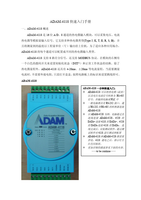
ADAM-4118快速入门手册一、ADAM-4118概述ADAM-4118是16位A/D、8通道的热电偶输入模块,可以采集电压、电流热电偶等模拟量输入信号,它支持多种热电偶类型(Type J, K, T, E, R, S, B),并且将测量到的温度以工程量单位(℃)输出给上位机。
为了适应各种应用场合,ADAM-4118的每个通道可以配置成不同的热电偶输入类型。
ADAM-4118支持8路差分信号,还支持MODBUS协议。
在模块的右侧有一个白色的拨码开关来设置初始化状态(INIT*)和正常工作状态的切换。
除了热电偶量程外,ADAM-4118还具有4-20ma、±20ma等电流量程,当需要测量电流时,不需要外接电阻,只需打开盒盖,按照电路板上的标识来设置跳线即可。
ADAM-4118规格说明AI 模拟量输入● 有效分辨率:16位● 通道:8路差分,可独立设置量程● 高共模电压:200Vdc● 通讯协议:ASCII 命令,Modbus 协议● 输入类型 & 量程范围50mV , ±100mV , ±500mV , ±1V , ±2.5V电流模式 ±20 mA, +4~20 mA● 隔离电压:3000VDC ● 过压保护:±60V● 采样速率:10/100 采样点每秒(通过测试软件设置)● 输入内阻:电压20M Ω,电流120Ω● 精确度:电压模式:±0.1% or better 电流模式& 高速模式:±0.2% or better ● 零点漂移:±6μV /℃● 跨度漂移:±25 ppm/° C● 共模抑制(CMR )@50/60Hz dB min● 内置看门狗● 内置 TVS/ESD 保护● 功耗 1.2W@24VDC跳线设置:ADAM-4118测量电流时需要跳线。
拆开盒盖,可以看到板上有八个跳线,按照下图或电路板标识进行跳线,测电流跳到“I ”端,测量电压保持跳线在“V ”端的出厂设置不变。
山特维克DL411-7生产钻机 说明书

T echnical Specification 7-6105-C 2014-12-18Sandvik DL411-7Production Drills1/4© 2014 S a n d v i k M i n i n g a n d C o n s t r u c t i onThe San dvik DL411-7 is an electro-hydraulic lon g-hole drilling rig for large-scale production drilling in underground mines.The rig has been design ed for vertical an d in clin ed plane rings and fans, parallel long production holes as well as long single holes. The 360° rotation and parallel coverage, together with wide tilt an gle ran ges forwards an d backwards, make the boom suitable to various drilling applications.Instrumentation and data drilling with various auto-mation option s allow maximum performan ce with superior drilling accuracy. Proven CAN-based tech-nology on board allows the operator to set the unit for any rock conditions. It also makes the upgrade of automation level easy, an d has a fault fin din g sys-tem, which reduces downtime.The machin e is based on a proven carrier for high mobility. Tramming is done from the operator's plat-form, and drilling from a remote position next to the machine.Carrier NC7N Boom ZR30Drilling module LFRC1600Rock drill HL710Hole diameter 64-102 mm Hole length Up to 54 m Control system TPC LH Cornering 3400 mmT otal weight21 000 kg(depending on options)2/4Coverage areaMAXIMUM DRIFT SIZEMINIMUM DRIFT SIZEDrilling Module HWW pH R LF16043245324514502100LF16053550355017502100LF16063855385520502100Included 100mm clearance on each sideAll dimensions in mm Rock DrillHL710Percussion power 19.5 kW Percussion pressure Max. 190 bar Percussion rate 42-52 Hz Rotation speedMax. 180 rpm Rotation torque (OMT250)Max. 1335 Nm Hole size64 - 102 mm Recommended drill steel 38-51 mm rods 64 mm tubes Shank adapter T38, T45, T51Weight 245 kg Length1035 mm Profile height286 mmShank lubrication deviceAir /oil mist, SLUShank lubrication compressor CT10, 1m³/min (7 bar)Air consumption 200 - 300 l/min Oil consumption 250 - 550 g/h #Power extractorHL710Technical Specification 2_1750Boom typeZR30Parallel coverage 3000mm Weight2 800kg Roll-over angle360°BoomTechnical Specification 4_1810LFRC160x x=4’ / 5’ /6’Capacity 29+1 rods/tubes Feed force 31kNFeed extensionLF1604: 1000mm LF1605: 1100mm LF1606: 1400mm Rod retainerPito 16Cuttings collectorCC1016Readiness for double tools Rods/T ubesStinger extensionLF1604: 1500mm LF1605/6: 1700mm#Sequence control Automatic rod/tube changing #Front stingerRequired for downholes Technical Specification 3_1557#Visual angle indicators Spirit levels#TMS DDSDrilling direction, depth and speed #Fan automation 360° fan drilling(Incl. one hole data drilling)#One hole data drillingAutomated single hole drillingInstrumentation optionsTechnical Specification 5_9202# Additional options features/components * Alternative options features/components3/4Machine dimensionsFEED L LF1604 3 000LF1605 3 300LF16063 600All dimensions in mmPowerpackHPP755 (55kW)Percussion pump 100cc variable displacement Rotation pump45cc variable displacement Boom movements pump28cc variable displacement Filtration size20 microns (pressure)10 microns (return)Oil tank volume 270 liters T ank filling Electric pump *T ank filling Manual pumpOil coolerWater cooled.Cooling capacity 1x45kW*Oil coolerAir cooled. Cooling capacity 2x30kWN/A with water hose reel*Biodegradable oils Shell Naturelle HFE46/HFE68#Vacuum pump for hydraulic oilHydraulic systemT ype TPC LHPower control Adjustable full powerAdjustable collaring power Anti-jamming control Adjustable anti-jamming pressureRotation control Adjustable rotation speed Flushing control Water flushing flow and pressure controlDrilling control panelPortable with cable remote control panel, 20m cableControl systemTechnical Specification 5_1300#Pressure cleaning system with reel5-15 bar#High pressure cleaning system with reelMax. 180 bar Cleaning system#Greasing unit with reel,pump and nozzleManual#Automatic greasing systemCarrier, boom and cassetteGreasing systems and optionsT otal input power 80 kW Main switchMSE 10Standard voltages 380-690 VAC *Optional voltage 1000 VACStarting method Star delta starter 380 VAC-690 VAC Soft starter 480 VAC, 575 VAC (USC)Direct on Line (DOL) 1000 VAC Voltage fluctuation ±10%Cable reelTCR3E with spooling system Cable reel control Control at operator station Batteries2x12V , 145Ah *Sealed AGM batteries 2x12V , 50Ah#Electric cable rubber or PUR Depending on voltage (see spec 5-4100)#Ground fault and overcurrent protection VYK #Auxiliary outlet 1 x 230V , 16A #Remote control for reel(s)At rear end #Three phase network outlet voltage readiness 380-690VAC only#Battery jump start FlushingWater flushing flow and pressure control. Air-mist flushing, optionWater pump WBP3Water pump capacity 215 l/min Water pump inlet pressure 2-7 bar Flushing water pressure Max. 20 bar*Optional compressorCT16 (11kW , 1.6m 3/min) orCT28 (18.5kW , 2.8m 3/min)External air connection IP5 air cleaner #Air mist flushing packages External water/air connection#End of the hole flushing1x60l air receivers, requires CT16 compressor#Water hose reel + hose THR2.5E +38mm (1½”), 65 metersFlushing system and options#Hand held fire extinguisher 1 pcs #Manual fire suppression system 6 nozzles #Automatic fire suppression system 6 nozzles #FS1000above 0°CFire suppression system and optionsTech. Spec. 5-9800# Additional options features/components * Alternative options features/components4/4Sandvik Mining and Construction OyP .O Box 100. FIN-33311 T ampere, Finland T el. +358 205 44 121, Fax +358 205 44 Sandvik Mining and Construction reserves the right to change this specification without further notice.© 2014 S a n d v i k M i n i n g a n d C o n s t r u c t i o nTramming dimensionsT ramming speedHorizontal: 15 km/h 14% = 1:7 = 8° 6,5km/h Gradeability / Inclination Max. 15° / 5°#Reduced tramming speed3rd gear lockoutT rammingSafety canopyFOPS (ISO 3449)Sound pressure level according to EN791Operator station: 102 dB(A)Emitted: 127 dB(A)SeatErgonomic, adjustableFor tramming including seat belt Reversing alarm Standard#Reversing cameraOn machine rear and side Operator’s stationFront lights(combined working and driving) 4 x 35W HID (24V) Rear working lights 2 x 35W HID (24V) Rear driving lights2 x 35W HID (24V) Parking Rear brake/park lights 2 x Red LEDPortable working lights 2 x 35W HID (24V) Positioning lights2 x Laser type Stair and service lights LED#Amber flashing lightFlashing (24V)Lights and options#RegionalAUS, USC, EUR *Harsh water packagesBasicSee spec sheet 5-9100PackagesCarrierNC7NCarrier type Wheel mounted, frame steering Frame steering ± 40°Rear oscillation ± 10°Ground clearance 320 mmDiesel engineMB OM904LA, 110kW , Tier 3Exhaust catalyser+muffler StandardT ransmission Hydrodynamic, Spicer T20 000Axles SpicerT yres 12.00-20/20RL*T yres12.00-20/28PR ECR *Optional tyresFoam filled tyresService Brakes, park and emergency SAHR type, fail safe wet disc brakes Fuel tank 140 litersHydraulic jacksFront frame stabilizer TJ60 (rear)Hand throttle Standard #Fast filling systemComplete #Wheel chocks and holders2 piecesCarrier#Spare rock drill #Spare wheel assembly Standard or foam filled #Special tools for rock drill #DocumentationExtra manualsExtra items# Additional options features/components * Alternative options features/components。
ADAM4117模块使用手册.pdf

ADAM-4117快速入门手册一、ADAM-4117概述ADAM-4117是16位A/D、8通道的模拟量输入模块,可以采集电压、电流等模拟量输入信号,并且为所有通道都提供了独立的可编程的输入范围。
在工业测量和监控的应用中,ADAM-4117具有良好的性价比。
它不仅能够用于恶劣的环境中,而且还具有更加坚固型的设计。
ADAM-4117支持8路差分信号,还支持MODBUS协议。
在模块的右侧有一个白色的拨码开关来设置初始化状态(INIT*)和正常工作状态的切换。
ADAM-4117具有4-20ma、0-20ma、±20ma等电流量程,当您需要测量电流时,不需要外接电阻,只需打开盒盖,按照电路板上的标识来设置跳线即可。
ADAM-4117ADAM-4117一分钟快速入门:✧ADAM-4117可以将电压电流信号转换为RS-485信号,传输到电脑或PLC中✧一般电脑都具有RS-232接口,通过RS-232到RS-485的转换器连接ADAM-4117✧以ADAM-4520为例,电脑通过直连线连接ADAN-4520,4520的DATA+连接4117的DATA+,4520的DATA-连接4117的DATA-。
连线完成后,安装测试软件,通过测试软件对4117进行测试和配置✧ADAM-4117和ADAM-4520都需要供电,4117通电之后,指示灯呈红色闪烁状。
✧更加详细的描述参见下面的内容。
……to be continued……规格说明AI 模拟量输入⚫有效分辨率:16位⚫通道:8路差分,可独立设置量程⚫高共模电压:200Vdc⚫通讯协议:ASCII命令,Modbus协议⚫输入类型:mV,V(支持单双极性),mA⚫输入量程:0~150mV, 0~500mV, 0~1V, 0~5V, 0~10V, 0~15V,±150 mV, ±500 mV, ±1V, ±5 V, ±10 V, ±15V, 0~20mA,±20 mA, 4~20mA⚫隔离电压:3000VDC⚫过压保护:±60V⚫采样速率:10/100 采样点每秒(通过测试软件设置)⚫输入内阻:电压20MΩ,电流120Ω⚫精确度:电压模式:±0.1% or better 电流模式:±0.2% or better⚫零点漂移:±6μV/℃⚫跨度漂移:±25 ppm/° C⚫共模抑制(CMR)@50/60Hz dB min⚫内置看门狗⚫内置TVS/ESD保护⚫功耗跳线设置:当ADAM-4117测量电流时,需要跳线。
ADAM4017
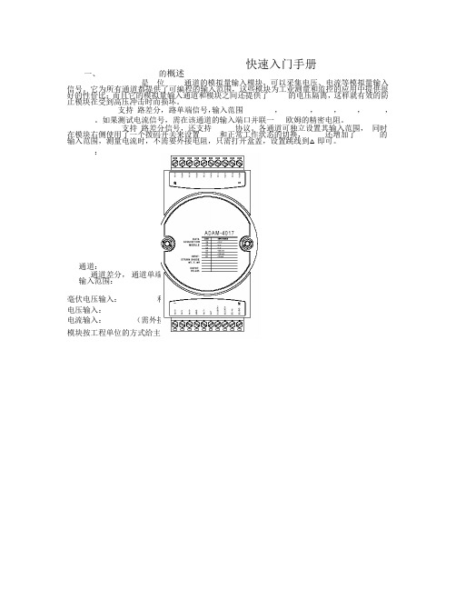
快速入门手册一、的概述是位通道的模拟量输入模块,可以采集电压、电流等模拟量输入信号。
它为所有通道都提供了可编程的输入范围,这些模块为工业测量和监控的应用中提供很好的性价比;而且它的模拟量输入通道和模块之间还提供了的电压隔离,这样就有效的防止模块在受到高压冲击时而损坏。
支持路差分,路单端信号,输入范围,,,,,。
如果测试电流信号,需在该通道的输入端口并联一欧姆的精密电阻。
支持路差分信号,还支持协议。
各通道可独立设置其输入范围,同时在模块右侧使用了一个拨码开关来设置和正常工作状态的切换,还增加了的输入范围,测量电流时,不需要外接电阻,只需打开盒盖,设置跳线到△即可。
:通道:通道差分,通道单端输入范围:毫伏电压输入:和电压输入:和电流输入:(需外接Ω电阻)模块按工程单位的方式给主机数据(,,)跳线设置: .默认设置是六通道差分,两通道单端.的技术说明ADAM-4017 差分通道输入(0 通道~5 通道)二、硬件连线ADAM-4017 单端输入(6 通道,7 通ADAM-4017+ 8 通道模拟量输入模块接线图二线制电流变送器和模拟量输入通道的接线方法变送器的“ ”接供电电源的高电压端,变送器的“”接模块板卡的,接电源对应的低电压端()。
注意在模块板卡的和并联电阻。
三、的使用的应用软件的安装把随机附带光盘放入计算机的光驱中,出现如下画面:选择安装选项,出现如下安装界面:根据后续的软件安装提示,完成的安装。
机上就会出现的软件如下图的快速使用1.选中 COM1 或 COM2,点击工具栏快捷键 search:2.弹出“Se arch Ins talled M odules ”窗口,提示扫描模块的范围,允许输入0~255。
RS-485 网络扫描如下图所示3.点击模块,进入测试/配置界面:4.ADAM-4017+还支持Modbus协议,如下所示:(Modbus寄存器支持列表请见说明书)5.终端(Terminal)在 TOOL 菜单,选择 Terminal 功能,弹出一个【Terminal】对话框,用于测试命令。
亚历山大-伯兰迪 8位灰码编码器输入模块说明书

1AllenĆBradleyGray Encoder (12Ć24 VDC)Input Module (Cat. No. 1771-DL)Product Data The Gray Encoder (12-24 VDC) Input Module converts an 8-bit Gray codefrom an absolute encoder to an 8-bit binary number for input to anAllen-Bradley programmable controller.The module also has a 120 V AC zero-speed triac switch which is on whilethe Gray encoder is in motion. The switch turns off after a selectable delaywhen the module detects that motion has stopped. You can use this switchas a safety interlock to open the drive circuit after motion stops or if theencoder should fail.The Allen-Bradley 8-bit Gray Encoder (Bulletin 845A-SJZ3DN6DW iscompatible with this encoder module.The encoder module is shipped with wiring arm (cat. no. 1771-WB).Description2The module receives its inputs from an encoder that detects rotational position, 0-360°, and converts position values to a corresponding 8-bit Gray code, 0-255. The encoder transmits coded position values to the module over a multiconductor cable (figure 1).Figure 1Block Diagram of Encoder and ModuleModule OutputsThe module converts 8-bit Gray code to 8-bit binary, and places these values on the backplane of the I/O chassis. The processor or remote I/O adapter reads these values in the same manner it reads data from a discrete I/O module. Values are read into the processor’s input image table word address corresponding to the module’s location in the I/O chassis: upper byte for slot 1, lower byte for slot 0.Zero Speed SwitchThe encoder module has a zero-speed triac switch (between terminals 11 and 12) which remains on until the module detects that motion has stopped.An adjustable time delay opens the switch after a delay. You adjust the delay time between 0.3 and 6.0 seconds using the trim pot located under the zero-speed indicator on the front of the module: counter-clockwise for shorter delay, clockwise for longer delay. It is factory set for 6.0 seconds.Module Inputs3The switch is rated at 0.5 A at 120 V AC, 47-63 Hz. Use this switch only toopen a “sealed-in” circuit (figure 2) such as for a motor starter. Do not useto initiate a “sealed-in” circuit.Figure 2Zero Speed Switch CircuitYou may need additional surge suppression to protect the triac switch fromthe motor starter. A load with large inductive characteristics can generatevoltage transients which exceed the switch’s internal surge current rating.Since switching frequency and load impedance vary with application, wecannot specify a particular suppressor for your motor starter. The tablebelow offers some suggestions for selecting a suppressor.The module has a 1 A fuse located on the circuit board inside the module.This fuse is in series with the triac switch, and will blow if the maximumsurge current exceeds 2 A for 10 ms.4Electrostatic DamageUnder some conditions, electrostatic discharge can degrade performance or damage the module. If you observe the following precautions you can guard against electrostatic damage.Touch a grounded object to discharge yourself before handling themodule.Do not touch the backplane connector or connector pins.When replacing the fuse, do not touch other circuit components inside the module. If available, use a static-safe work station.Replacing the FuseReplace the fuse as follows:Remove cover by unscrewing four corner screws.Remove the circuit board and turn it over.Locate the fuse on the lower side, and replace.Re-assemble in reverse order.Status IndicatorsThe front panel of the encoder module contains nine red LED status indicators.The top indicator lights when the zero-speed triac switch is ON. Each of the remaining eight indicators corresponds to a single Gray code bit, and lights when the logic state of the bit is OFF.The encoder module requires 120 mA from the I/O chassis power supply. Total this amount with the current requirements of other modules in the chassis to guard against overloading the backplane and backplane power supply.Backplane Power5Customer Power SupplyThe module also requires a 12 to 24 VDC power supply which you connect to the wiring arm and absolute encoder (figure 3). The encoder driving circuit sinks 15 mA at 24 VDC or 6 mA at 12 VDC per Gray code input.Multiply this by eight for each encoder powered by this supply. Some absolute encoders may require an additional 5 VDC supply.Figure 3Wiring Diagram Use Belden 9556 multiconductor shielded cable (or equivalent) to connectthe encoder to the module’s wiring arm (figure 3). Ground the cable at oneend, only. We recommend that you ground it at an I/O chassis mountingstud. Wrap the drain wire and shield together and connect both to themounting stud. Limit the cable length to 50 feet.Wiring6WARNING: Remove power from the 1771 I/O chassisbackplane and wiring arm before removing or installing an I/Omodule.Failure to remove power from the backplane or wiring armcould cause module damage, degradation of performance, orinjury.Failure to remove power from the backplane could causeinjury or equipment damage due to possible unexpectedoperation.Plastic keying bands are shipped with each I/O chassis. These bands help ensure that only a selected type of module can be placed in a particular module slot. They also help to align the module with the backplane connector.Each module is slotted at its rear edge. The position of the keying bands on the upper backplane connector must correspond to these slots to allow insertion of the module. For the 1771-DL Gray Encoder Module, position the keying bands as follows:Between 4 and 6Between 24 and 26Keying7Input G one 8Ćbit Absolute Gray Encoder Digital Resolution G 1 part in 256HighĆtrue Logic G from a 7406, 7407, or equivalent TTL circuit with an open collector output G module sources current to user device Logic State G logic 1: 10Ć27 VDC G logic 0 : 0Ć2 VDC Input Sourcing Current G 6 mA per bit at 10 VDC G 15 mA per bit at 27 VDC Input Filter Time Delay G 1 millisecond (max.)Backplane Current G 120 mA at 5 VDC ZeroĆSpeed Triac SwitchG output voltage:120 VAC (92Ć138 VAC,47Ć63 Hz)G output time delay:adjustable from 0.3 to 6.0seconds(factory set at 6 seconds)G continuous output current:0.5 A (max.)G maximum surge current:2 A for 10 msG minimum load current:50 mAG ON state" voltage drop:2V at 100 mA load currentG OFF state" leakage current:5 mA (max.)G output fuse:8 AG, 1 A normal blowEnvironmental ConditionsG operating temperature:0 to 60° C (32 to 140° F)G storage temperature:-40 to 85° C (-40 to 185° F)G relative humidity:5 to 95% (without condensation)Keying Band PositionsG between 4 and 6G between 24 and 26© 1986 Allen-Bradley CompanyPLC is a registered trademark of Allen-Bradley CompanySpecifications8With offices in major cities worldwideWORLD HEADQUARTERS Allen-Bradley 1201 South Second Street Milwaukee, WI 53204 USA Tel: (1) 414 382-2000Telex: 43 11 016FAX: (1) 414 382-4444EUROPE/MIDDLE EAST/AFRICA HEADQUARTERS Allen-Bradley Europe B.V .Amsterdamseweg 151422 AC Uithoorn The Netherlands Tel: (31) 2975/43500Telex: (844) 18042FAX: (31) 2975/60222ASIA/PACIFIC HEADQUARTERS Allen-Bradley (Hong Kong)Limited Room 1006, Block B, Sea View Estate 28 Watson Road Hong Kong Tel: (852) 887-4788Telex: (780) 64347FAX: (852) 510-9436CANADA HEADQUARTERS Allen-Bradley Canada Limited 135 Dundas Street Cambridge, Ontario N1R 5X1Canada Tel: (1) 519 623-1810FAX: (1) 519 623-8930LATIN AMERICA HEADQUARTERS Allen-Bradley 1201 South Second Street Milwaukee, WI 53204 USA Tel: (1) 414 382-2000Telex: 43 11 016FAX: (1) 414 382-2400As a subsidiary of Rockwell International, one of the world’s largest technology companies — Allen-Bradley meets today’s challenges of industrial automation with over 85 years of practical plant-floor experience. More than 11,000 employees throughout the world design, manufacture and apply a wide range of control and automation products and supporting services to help our customers continuously improve quality, productivity and time to market. These products and services not only control individual machines but integrate the manufacturing process, while providing access to vital plant floor data that can be used to support decision-making throughout the enterprise.Publication 1771-2.29 — June 1986Supersedes Publication 1771-941 — September 1981PN 955099-78Printed in USA。
ADAM-4117测试文档
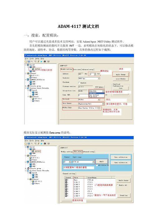
ADAM-4117测试文档一:搜索,配置模块:用户可以通过光盘或者技术支持网站,安装Adam/Apax .NET Utility测试软件。
首先把模块侧面的拨码开关拨到INIT一边,表明模块在初始化的状态下,可以修改模块的地址,波特率,协议,数据结构等参数,具体的修改过程如下截图:模块实际显示被测值Data area的说明:初始化状态下的校准功能,一般情况下,用户无需自行校准。
当模块使用几年后,可能会产生一些零点漂移,在这种情况下,如果您有标准信号源,您可以自行校准,也可以寄到研华维修部门来校准。
校准过程如下,只需校准一个通道,所有通道便都已经校准。
按照界面显示值,直接校准即可。
Trend Log画图功能,可以把采集到的数据,按照指定的路径和方式保存起来,格式为Excel,命名为WaveScanLog_Adam4117(可以有保存的时间显示)或者HistoryLog_Adam4117说明如下:保存后的表格形式如下:初始化高级设置的界面:块就可以再正常状态下工作了。
二:命令测试1.Modbus命令测试在英文说明书的附录B部分有寄存器地址的说明,如下:先把模块配置成Modbus协议,截图如图下:Modbus协议下,在CH7通道Vin7+和Vin7管脚间-接1.5V干电池,其他通道悬空,显示数值如下:用软件的测试功能,测试结果如下:用普通的串口调试助手,发送Modbus指令,读取八个通道的数值。
注意::模拟量占一个字长(16bit),返回值用4个十六进制数表示一个字长,即一个通道注意的读出值;若模块为16位的,则模拟量0~10V对应于十进制的0~65535。
2.ASCII(研华协议)命令测试在英文说明书中,有详细的指令说明,如下的指令表:用软件的测试结果如下:3.Burn-out断线检测功能测试ADAM-4117在输入4~20ma信号输入时,有短线检测的功能,当CH0设定输入范围为4~20ma ,即显示Burn,表明断线。
ADAM-4117模块使用手册
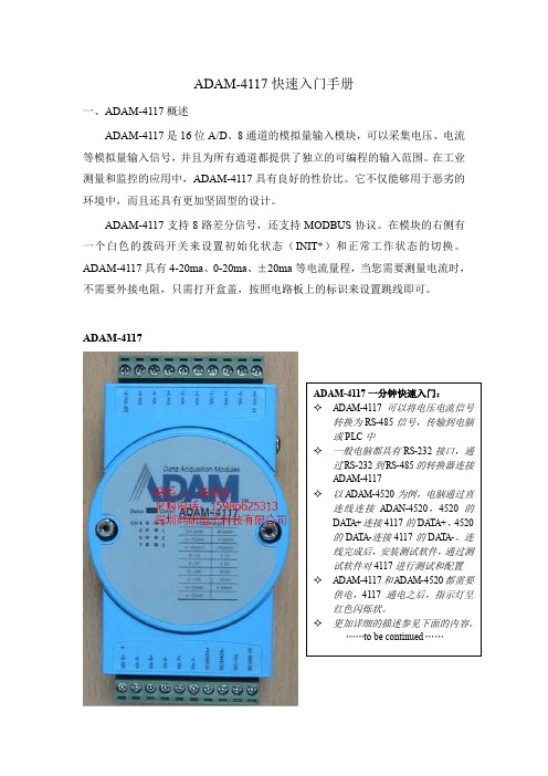
ADAM-4117快速入门手册一、ADAM-4117概述ADAM-4117是16位A/D 、8通道的模拟量输入模块,可以采集电压、电流等模拟量输入信号,并且为所有通道都提供了独立的可编程的输入范围。
在工业测量和监控的应用中,ADAM-4117具有良好的性价比。
它不仅能够用于恶劣的环境中,而且还具有更加坚固型的设计。
ADAM-4117支持8路差分信号,还支持MODBUS 协议。
在模块的右侧有一个白色的拨码开关来设置初始化状态(INIT*)和正常工作状态的切换。
ADAM-4117具有4-20ma 、0-20ma 、±20ma 等电流量程,当您需要测量电流时,不需要外接电阻,只需打开盒盖,按照电路板上的标识来设置跳线即可。
ADAM-4117规格说明AI 模拟量输入●有效分辨率:16位●通道:8路差分,可独立设置量程●高共模电压:200Vdc●通讯协议:ASCII命令,Modbus协议●输入类型:mV,V(支持单双极性),mA●输入量程:0~150mV, 0~500mV, 0~1V, 0~5V, 0~10V, 0~15V,±150 mV, ±500 mV,±1V, ±5 V, ±10 V, ±15V, 0~20mA,±20 mA, 4~20mA●隔离电压:3000VDC●过压保护:±60V●采样速率:10/100 采样点每秒(通过测试软件设置)●输入内阻:电压20MΩ,电流120Ω●精确度:电压模式:±0.1% or better 电流模式:±0.2% or better●零点漂移:±6μV/℃●跨度漂移:±25 ppm/° C●共模抑制(CMR)@50/60Hz dB min●内置看门狗●内置TVS/ESD保护●功耗1.2W@24VDC跳线设置:当ADAM-4117测量电流时,需要跳线。
ADAM-4117模块使用手册

ADAM-4117快速入门手册、ADAM-4117概述ADAM-411是16位A/D 、8通道的模拟量输入模块,可以采集电压、电流等 模拟量输入信号,并且为所有通道都提供了独立的可编程的输入范围。
在工业测量和监控的应用中,ADAM-411;具有良好的性价比。
它不仅能够用于恶劣的环境 中,而且还具有更加坚固型的设计。
ADAM-4117支持8路差分信号,还支持 MODBU 协议。
在模块的右侧有一个 白色的拨码开关来设置初始化状态 (INIT*)和正常工作状态的切换。
ADAM-4117 具有4-20ma 0-20ma 土 20ma 等电流量程,当您需要测量电流时,不需要外接 电阻,只需打开盒盖,按照电路板上的标识来设置跳线即可。
ADAM-41170~150mV,0~500mV,0~1V, 0~5V, 0~10V, 0~15V, ± 150 mV, ± 500mV, ± 1V, ± 5 V, ± 10 V, ± 15V, 0~20mA, ± 20 mA, 4~20mA隔离电压:3000VDC规格说明AI 模拟量输入有效分辨率:16位通道:8路差分,可独立设置量程 高共模电压:200Vdc通讯协议:ASCII 命令,Modbus 协议输入类型:mV V (支持单双极性),mA 输入量程过压保护:土60V采样速率:10/100采样点每秒(通过测试软件设置)输入内阻:电压20MQ,电流120Q精确度:电压模式:土% or better 电流模式:土% or better零点漂移:土6yVC跨度漂移:土25 ppm/ ° C共模抑制(CMR @50/60Hz dB min内置看门狗内置TVS/ESD保护功耗@24VDC 跳线设置:当ADAM-4117测量电流时,需要跳线。
将盒盖拆开,可以看到电路板上有八个跳线,按照下图或者按照电路板上的标识进行跳线,测量电流需要将跳线跳到“I”端,测量电压则需要保持跳线在“ V'端的出厂设置不变。
- 1、下载文档前请自行甄别文档内容的完整性,平台不提供额外的编辑、内容补充、找答案等附加服务。
- 2、"仅部分预览"的文档,不可在线预览部分如存在完整性等问题,可反馈申请退款(可完整预览的文档不适用该条件!)。
- 3、如文档侵犯您的权益,请联系客服反馈,我们会尽快为您处理(人工客服工作时间:9:00-18:30)。
ADAM-4117快速入门手册一、ADAM-4117概述ADAM-4117是16位A/D 、8通道的模拟量输入模块,可以采集电压、电流等模拟量输入信号,并且为所有通道都提供了独立的可编程的输入范围。
在工业测量和监控的应用中,ADAM-4117具有良好的性价比。
它不仅能够用于恶劣的环境中,而且还具有更加坚固型的设计。
ADAM-4117支持8路差分信号,还支持MODBUS 协议。
在模块的右侧有一个白色的拨码开关来设置初始化状态(INIT*)和正常工作状态的切换。
ADAM-4117具有4-20ma 、0-20ma 、±20ma 等电流量程,当您需要测量电流时,不需要外接电阻,只需打开盒盖,按照电路板上的标识来设置跳线即可。
ADAM-4117规格说明AI 模拟量输入●有效分辨率:16位●通道:8路差分,可独立设置量程●高共模电压:200Vdc●通讯协议:ASCII命令,Modbus协议●输入类型:mV,V(支持单双极性),mA●输入量程:0~150mV, 0~500mV, 0~1V, 0~5V, 0~10V, 0~15V,±150 mV, ±500 mV, ±1V, ±5 V, ±10 V, ±15V, 0~20mA,±20 mA, 4~20mA●隔离电压:3000VDC●过压保护:±60V●采样速率:10/100 采样点每秒(通过测试软件设置)●输入内阻:电压20MΩ,电流120Ω●精确度:电压模式:±0.1% or better 电流模式:±0.2% or better●零点漂移:±6μV/℃●跨度漂移:±25 ppm/° C●共模抑制(CMR)@50/60Hz dB min●内置看门狗●内置 TVS/ESD保护●功耗1.2W@24VDC跳线设置:当ADAM-4117测量电流时,需要跳线。
将盒盖拆开,可以看到电路板上有八个跳线,按照下图或者按照电路板上的标识进行跳线,测量电流需要将跳线跳到“I”端,测量电压则需要保持跳线在“V”端的出厂设置不变。
跳线完成后,可以使用万用表测量V+与V-之间,正常应该有120Ω的电阻。
二、ADAM-4117硬件连线如果需要连接二线制变送器,可以参考下图的接线方法。
如果变送器是电流变送器,请注意模块内部的电流跳线。
三、测试软件(Utility)的使用ADAM-4117适用ADAM-4000-5000 Utility(old)或ADAM .Net Utility(new). 下面以ADAM .Net Utility为例,演示ADAM-4117的安装、配置和测试过程。
1. Utility的安装将ADAM-4117盒子里附带的小光盘放入计算机的光驱中,取消自动播放,使用右键打开,先按照如下路径安装Microsoft DotNet framework,即下图中的dotnetfx.exe。
安装完Microsoft .net fx之后,再安装测试软件Advantech Utility:注意:如果PC是Win 2000/XP操作系统,需要运行的是Win 32下的安装文件安装完成之后,可以通过如下路径打开Adam .net Utility:如果希望使用年代比较久一些的ADAM-4000-5000 Utility,也可以通过光盘上的如下路径安装这个测试软件:2. Adam .net Utility的快速使用Step 1选择连接到ADAM-4117的com口,点击上面的放大镜图标search:注意:如果使用串口扩展卡,扩展出来的com口序号较大(例如com5),可能需要您点击Utility上面Setup菜单中的refresh按钮来显示所有的com口一般情况下,鼠标点击到com1时,右侧setting中的参数无需改变,除非您确认您已经修改了ADAM-4520以及ADAM-4117的串口通讯参数(例如波特率、数据位等)Step 2一般情况下,无需更改弹出窗口的Starting address,直接点击Start 即可。
这项参数的含义是从哪个RS-485地址开始搜索,一直搜索到Address 255为止。
Step 3搜索到模块后,可以点击Cancel按钮取消搜索,点击左侧菜单中的模块名称进入模块配置页面。
在上面的Utility画面中,可以配置RS-485 地址(Address)、波特率(Baudrate)、通讯协议(Procotol)等。
修改完毕后,点击右上角的“Apply change”保存设置到模块的芯片里。
注意:上面截图中的ADAM-4117为初始化状态,所以可以修改波特率和通讯协议等参数。
切换初始化状态的开关在模块右侧,拨到INIT为初始化状态(配置状态),拨到Normal为用户正常使用状态。
切换开关的操作必须在模块断电状态下进行才有效。
3. ADAM-4117的MODBUS协议ADAM-4117支持MODBUS RTU协议,在模块初始化状态的情况下,可以在Utility下通过“Protocol”项的下拉菜单将协议更改为“Modbus”。
更改协议之后,将拨码开关拨到Normal,可以通过MODBUS寄存器地址40001~40008来读取CH0~CH8的数值。
更加详细的MODBUS地址对照表参见ADAM-4100系列的英文手册。
Modbus协议读到的数值为16进制或10进制的整数,数值从0-65535,分别对应量程的上下限。
例如,当量程为±10V时,如果输入的电压值为0V,则读取到的Modbus数值为32767。
4. ADAM-4117 的ASCII协议将ADAM-4117的拨码开关拨到Normal状态后上电,用鼠标点一下ADAM-4117所在的com口,再点一下上面的黄色闪电图标,打开Terminal工具。
如果希望读取ADAM-4117全部8个通道的数值,可以使用的ASCII命令是“#”+“地址”+“回车(cr)”;例如当4117地址为1时,可以发送命令“#01(cr)”.更加详细的ASCII指令表参见ADAM-4100系列英文手册。
注意:在ADAM Utility中,已经默认在ASCII命令后面增加回车,所以看不出来需要使用回车。
如果使用网络上的“串口调试助手”或自己编写程序,那么一定要在命令后面添加回车(对应的ASCII为0D)才会收到4117的回复。
5. 校准(警告:非必要无需自行校准!)ADAM-4117出厂时已经经过校准,所以一般情况下,用户无需自行校准。
当模块使用几年后,可能会产生一些零点漂移,在这种情况下,如果您有标准信号源,您可以自行校准,也可以寄到研华维修部门来校准。
校准过程如下:Step1:将模块右侧的拨码开关拨到INIT状态Step2:点击Zero calibration按钮,会弹出一个对话框提示“请提供0.0mV 的电压到模块的CH0通道”。
此时,在CH0通过标准信号源接入0.0mV的信号后,点击“Apply”。
如果您没有接入标准信号源,不小心误点了Zero calibration按钮,请点击弹出窗口右上角的红叉,退出校准过程。
务必不要在没有外接0.0mV信号的情况下点击“Apply”按钮!!!!!注意:如果您使用的不是+/-10V的量程,需要您在CH0输入的信号可能不是0mV,请您按照弹出对话框的提示来输入实际信号!Step3:点击Span calibration按钮,会弹出一个对话框提示“请提供10.0V 的电压到模块的CH0通道”。
此时,在CH0通过标准信号源接入10.0V的信号后,点击“Apply”。
如果您没有接入标准信号源,不小心误点了Zero calibration按钮,请点击弹出窗口右上角的红叉,退出校准过程。
务必不要在没有外接10.0mV信号的情况下点击“Apply”按钮!!!!!注意:如果您使用的不是+/-10V的量程,需要您在CH0输入的信号可能不是0mV,请您按照弹出对话框的提示来输入实际信号!四、ADAM-4100的软件编程ADAM-4117的编程,主要的流程就是通过串口发出命令,然后收取模块的回复。
当使用Modbus协议时,通过串口发出的命令就是Modbus命令,具体可以参考Modbus RTU的标准协议内容,由于是公开的通用协议,在此不再赘述。
如果使用 2003/2005对Modbus进行编程,可以参考下面Step3的例程。
下面主要讲解如何通过ASCII协议来对ADAM-4117模块进行编程。
注意:更加详细的ASCII指令表参见ADAM-4100系列英文手册。
Step1 使用Utility上的Terminal功能测试(参见上面3.4小节中的内容),确认ADAM-4117配置正确,可以接收ASCII命令。
如果使用Visual Studio6.0编程,请参考Step2的内容;如果使用Visual Studio200/2005,请参考Step3.Step2 (使用VS6.0编程)参考ADAM-4100系列英文手册18页-23页的内容,有VB 6.0编程的讲解。
如果使用VC、Labview等编程,可以参考如下的程序流程图进行编程Step3 (使用VS2003/2005编程)安装光盘里的ADAM .Net class library,安装之后可以在C盘的如下路径找到VB和VC#的例程:C:\Program Files\Advantech\ Class Library\VS2003\Samples\Win32对于ADAM-4117模块,使用ASCII协议时,可以参考Adam4017P_18P或Comporttest例程;使用Modbus协议时,可以参考ModbusRTU例程。
五、ADAM-4117的特殊功能1. 高速(100Hz)采样:通过Utility里的“Integration Time”更改,将50/60Hz 更改为“High Speed”,即为4117的高速采样模式2. 地址模式:在带电状态下,将4117右侧的拨码开关拨到INIT状态,4117的8个绿色小指示灯会以二进制的形式显示当前4117的地址3. Adam .net Utility的画图功能:点击Utility画面上的“Trend Log”按钮,可以选择通道进行画图,在画图开始之前点击“Save”按钮,可以将绘制图形的数据以Excel表格的形式保存下来。
……………………………………… The end ………………………………………。