1W大功率LED规格书
LED显示屏技术规格书
显示面积
6.75m×3.8m=25.65㎡
3
像素密度
27777点/㎡
4
像素点间距
6mm
5
显示灰度
红色、绿色、蓝色256级灰度
6
显示颜色
16777216
7
驱动方式
1/8扫描
8
刷新频率
150帧/秒
9
数据传输
超五类网线
10
传输距离
≤100米
11
最大功耗
1000W/㎡
12
寿命
大于10万小时
13
电源
三相五线,220V供电
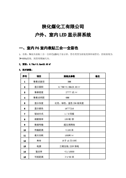
陕化煤化工有限公司
户外、室内LED显示屏系统
一、室内P6室内表贴三合一全彩色
1,名称:P6室内表贴三合一全彩色LED电子显示屏,管芯类型为原装美国科瑞管芯,控制系统为TW-NOVA系统,到货周期30天内。
2,面积:6.75m×3.8m=25.65㎡
3,技术参数:
序号
项目
规格及参数
备注
1
像素点直径
3mm
14
盲点率
≤1/10000
15
可视距离
≥1-50米
16
工作环境温度
-20℃-----70℃
17
工作环境湿度
10﹪-----95﹪
18
框架材料
钢结构
19
安装方式
壁挂式
20
连续工作时间
≥72小时
4,系统组成:
名称
品牌/规格
说 明
LED显示屏
原装美国科瑞管芯
P6室内表贴三合一全彩色,面积6.75M*3.8m。
1m
柱子柱子
2.0m
LED灯具规格书

①. 9W LED 瓦楞灯●详细技术参数:光源功率:9W 灯具功率:8~9W 光源品牌:美国流明 光源颗数:3pcs 单颗3W 输入电压: DC24V材 质:压铸铝 防护等级: IP65 光 通 量:>950lm色 温: 6000-6500KLED 发光效率:>110lm/W 灯具效率: >80 %显色指数: Ra >75 灯体温度: ≤50℃工作环境温度:-25℃ ~ +75℃ 灯体尺寸:Φ100mm 光源使用寿命:≥50000H 安装方式:螺丝固定●产品特点:1、采用进口芯片,自主封装。
2、独特钢化光学玻璃,透光率达95%以上,光线更为柔和。
3、良好的光还原性及显色性、色彩显示优良,表现力强。
4、高规格压铸铝材,抗腐蚀,抗氧化效果好,能抵御恶劣环境。
产品图片 (仅供参考)②. 6W LED 瓦楞灯●详细技术参数:光源功率:6W 灯具功率:6~7W 光源品牌:美国流明 光源颗数:3pcs 单颗2W 输入电压: DC24V 材 质:压铸铝 防护等级: IP65光 通 量:>650lm 色 温: 6000-6500K LED 发光效率:>110lm/W灯具效率: >80 % 显色指数: Ra >75 灯体温度: ≤50℃工作环境温度:-25℃ ~ +75℃ 灯体尺寸:Φ75mm 光源使用寿命:≥50000H 安装方式:螺丝固定●产品特点:1、采用进口芯片,自主封装。
2、独特钢化光学玻璃,透光率达95%以上,光线更为柔和。
3、良好的光还原性及显色性、色彩显示优良,表现力强。
4、高规格压铸铝材,抗腐蚀,抗氧化效果好,能抵御恶劣环境。
产品图片 (仅供参考)③. 3W LED 射灯●详细技术参数:光源功率:3W 灯具功率:3~4W 光源品牌:美国流明 光源颗数:3pcs 单颗1W 输入电压: DC24V材 质:压铸铝 防护等级: IP65光 通 量:>330lm 色 温: 6000-6500K LED 发光效率:>110lm/W灯具效率: >80 % 显色指数: Ra >75 灯体温度: ≤50℃工作环境温度:-25℃ ~ +75℃ 灯体尺寸:Φ60mm 光源使用寿命:≥50000H 安装方式:螺丝固定●产品特点:1、采用进口芯片,自主封装。
led驱动电源规格书

LED驱动电源规格书
3*1w
产品特性
●恒流型,符合LED特性驱动
●隔离型:安全可靠
●全密闭模块封装结构
●直接封装于GU10灯头内部,适用于各种带GU10接头的LED灯具
●可靠性高,使用寿命长
产品说明:
H1WGU10恒流驱动电源是制作一体化LED灯具的专用器件,适用于各种带
E27接头的LED灯具,驱动单只1W大功率发光二极管工作,220V交流市电供电,输出脉动恒定电流。
本驱动器使用高频脉宽调制式开关变换电路,体积小,电压适应范围宽,工作稳定,输入/输出隔离,安全性好。
本驱动器为全密闭模块封装结构,适合在高湿度,高粉尘,强震动等环境下使用。
技术参数:
输入电压:AC 85--260V
输出电压:DC9-11V
输出电流:280-330mA
效率:>70%
驱动管数:3只1W
使用温度:-20-60℃
模块体积:如图所示
输出线长:50MM,剥线长3MM
使用方法:
本模块有4根引出线,2根白色线是输入线,接交流电,红/白线是输出线,红线接发光管正极,白线接发光管负极,驱动3只1瓦大功率发光二极管工作。
使用注意事项:
使用本模块时必须接好发光管再接通电源,不能长时间空载通电。
产品展示图。
LED规格书
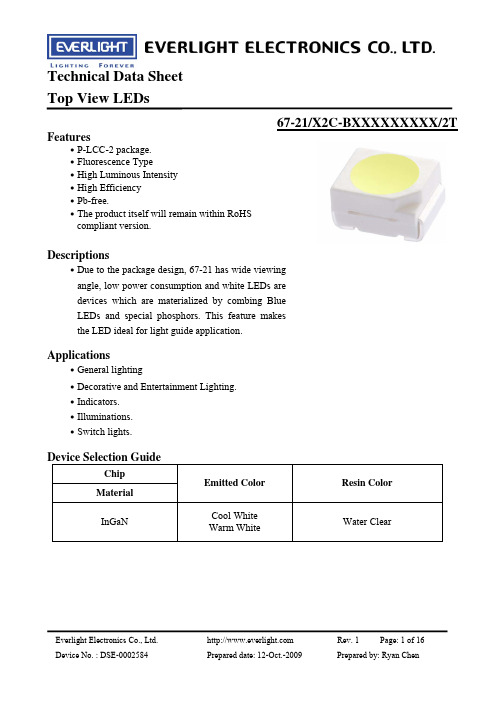
Technical Data Sheet Top View LEDs67-21/X2C-BXXXXXXXXX/2TCarrier Tape Dimensions: Loaded Quantity 2000 pcs Per Reel.Note: Tolerance unless mentioned is ±0.1mm; Unit = mmMoisture Resistant PackagingLabelAluminum moisture-proof bagDesiccantLabelEverlight Electronics Co., Ltd. Device No. : DSE-0002584 Prepared date: 12-Oct.-2009Rev. 1Page: 11 of 16Prepared by: Ryan ChenTechnical Data Sheet Top View LEDs67-21/X2C-BXXXXXXXXX/2TReliability Test Items and ConditionsThe reliability of products shall be satisfied with items listed below. Confidence level:90% LTPD:10% Test Hours/Cycles 6 Min. Sample Size 22 PCS.No. 1Items Reflow SolderingTest Condition Temp. : 260℃±5℃ Min. 5sec. H : +100℃ 15min ∫ 5 min L : -40℃ 15min H : +100℃ 5min ∫ 10 sec L : -10℃ 5min Temp. : 100℃ Temp. : -40℃ IF = 20 mA 85℃/ 85%RHAc/Re 0/12Temperature Cycle300 Cycles22 PCS.0/13Thermal Shock High Temperature Storage Low Temperature Storage DC Operating Life High Temperature / High Humidity300 Cycles 1000 Hrs. 1000 Hrs. 1000 Hrs. 1000 Hrs.22 PCS.0/14 5 6 722 PCS. 22 PCS. 22 PCS. 22 PCS.0/1 0/1 0/1 0/1Everlight Electronics Co., Ltd. Device No. : DSE-0002584 Prepared date: 12-Oct.-2009Rev. 1Page: 12 of 16Prepared by: Ryan ChenTechnical Data Sheet Top View LEDs67-21/X2C-BXXXXXXXXX/2TPrecautions for Use1. Over-current-proof Customer must apply resistors for protection; otherwise slight voltage shift will cause big current change (Burn out will happen). 2. Storage 2.1 Do not open moisture proof bag before the products are ready to use. 2.2 Before opening the package: The LEDs should be kept at 30℃ or less and 90%RH or less. 2.3 After opening the package: The LED's floor life are 168 hours under 30℃ or less and 60% RH or less. If unused LEDs remain, it should be stored in moisture proof packages. 2.4 If the moisture absorbent material (silica gel) has faded away or the LEDs have exceeded the storage time, baking treatment should be performed using the following conditions. Baking treatment: 60±5℃ for 24 hours. 3. Soldering Condition 3.1 Pb-free solder temperature profile1~5 °C / Sec. 260°C. Max. 10 Sec. Max. 1~5 °C / Sec. Pre-heating 180~200°C 60 Sec. Max. Above 220°C120 Sec. Max.3.2 Reflow soldering should not be done more than two times. 3.3 When soldering, do not put stress on the LEDs during heating. 3.4 After soldering, do not warp the circuit board.Everlight Electronics Co., Ltd. Device No. : DSE-0002584 Prepared date: 12-Oct.-2009Rev. 1Page: 13 of 16Prepared by: Ryan ChenTechnical Data Sheet Top View LEDs67-21/X2C-BXXXXXXXXX/2T4. Soldering Iron Each terminal is to go to the tip of soldering iron temperature less than 350℃ for 3 seconds within once in less than the soldering iron capacity 25W. Leave two seconds and more intervals, and do soldering of each terminal. Be careful because the damage of the product is often started at the time of the hand solder. 5. Repairing Repair should not be done after the LEDs have been soldered. When repairing is unavoidable, a double-head soldering iron should be used (as below figure). It should be confirmed beforehand whether the characteristics of the LEDs will or will not be damaged by repairing.EVERLIGHT ELECTRONICS CO., LTD. Office: No 25, Lane 76, Sec 3, Chung Yang Rd, Tucheng, Taipei 236, Taiwan, R.O.CTel: 886-2-2267-2000, 2267-9936 Fax: 886-2267-6244, 2267-6189, 2267-6306 Everlight Electronics Co., Ltd. Device No. : DSE-0002584 Prepared date: 12-Oct.-2009Rev. 1Page: 14 of 16Prepared by: Ryan Chen。
LED灯饰图片及规格书

LED射灯规格书

深 圳 市 施 瑞 森 照 明 科 技 有 限 公 司 Shenzhen Schritzen Lighting Co.,Ltd系列名称:LED 射灯产品型号:SRZ-SE1401L-01外观尺寸:适用领域:适用于家居、办公等室内照明;商场、专卖店等橱窗;饰品、手机等柜台照明;酒吧、咖啡厅、娱乐场所等气氛照明色温范围:电气参数:光源寿命可选接头LED类型可选颜色CREE XPE 暖白 正白 冷白72g 30°净重发光角度光通量(LM):正白暖白冷白50,000H E27、E1475±5LM 65±5LM77±5LM 6500~7000K 3000~3500K7000~8000K 正白暖白冷白输入电压输出功率驱动方式AC85~265V 1W恒流驱动车铝Φ50*75银本色环境参数:外形参数:外壳材质外形尺寸外壳颜色产品特点:1、该款LED射灯采用1W大功率超高亮度LED作为发光源,使用恒流技术,提供稳定的输出电流,减小光衰,保证LED的使用寿命2、发光颜色丰富,有多种颜色可供客户选择3、采用宽电压供电AC85-265V ,全球通用4、采用高纯度铝合金外壳,高散热设计,表面阳极处理牢固耐用,色泽鲜艳,极富金属质感5、显色指数高,显示直观,清晰6、无频闪、无辐射,对人眼、身体无害,养眼环保。
7、通常情况下,寿命为30000 ~50000小时; 环境温度应用范围达-30°C ~45°C ,在规定的环境温度范围内,灯的亮度、颜色等方面都能达到最佳的效果工作温度储存温度IP等级 -30℃ ~ +45℃ -40℃ ~ +70℃IP50 室内使用深 圳 市 施 瑞 森 照 明 科 技 有 限 公 司 Shenzhen Schritzen Lighting Co.,Ltd2、发光颜色丰富,有多种颜色可供客户选择3、采用宽电压供电AC85-265V ,全球通用4、采用高纯度铝合金外壳,高散热设计,表面阳极处理牢固耐用,色泽鲜艳,极富金属质感5、显色指数高,显示直观,清晰6、无频闪、无辐射,对人眼、身体无害,养眼环保。
1W大功率LED规格书

V
H
3.4
3.6
I
3.6
3.8
J
3.8
4.0
60
60
70
70
70
80
光通量
Φv
IF=350[mA]
80
80
90
lm
90
90
100
100
100
ห้องสมุดไป่ตู้
120
正向电压测量允许误差 ±3%
光通量测量允许误差±10%
颜色档次
(正向电:350mA, 环境温度=25℃)
B7
B8
B9
C7
C8
C9
x 0.3057 0.3175 0.3193 0.3093 0.3175 0.3300 0.3300 0.3193 0.3300 0.3455 0.3436 0.3300 0.3032 0.3160 0.3175 0.3057 0.3120 0.3300 0.3300 0.3175 0.3300 0.3461 0.3455 0.3300
向电压,在严重的情况下个别 LEDs 可能超过它能承受最大参数。
3.清洗
推荐使用酒精作为LED的清洗溶剂.。当用其他溶剂清洗前需要确定是否会损坏包装和硅胶。根据国际惯 例氟利昂不能用来作为清洗LEDs的溶剂,不要用超声波清洗LEDs,当确实需要用超声波清洗LEDs时,超声 波清洗LEDs的作用取决于例如超声波强度和相关条件等因素。在清洗之前, 需要提前试验以确定是否会给 LEDs带来任何损害.
Tc
6200K-7000k
5500-6200
色区坐标误差: ±0.01 色温误差 :±10%
5000-5500
6200-7000
LUXEON 高功率光源1WLED说明
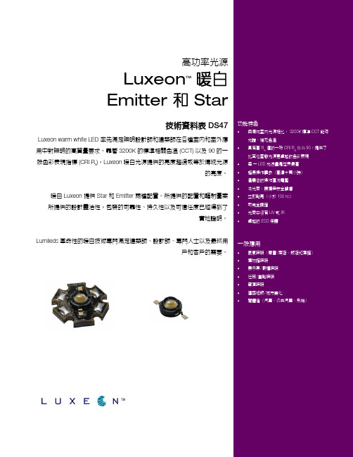
高功率光源
Luxeon ™
暖白 Emitter 和 Star
技術資料表 DS47
Luxeon warm white LED 率先滿足照明設計師和建築師在各種室內和室外應用中對照明的高質量要求。
靠著 3200K 的標準相關色溫 (CCT) 以及 90 的一般色彩表現指標 (CRI R a ),Luxeon 暖白光源提供的亮度超過或等於傳統光源
的亮度。
暖白 Luxeon 提供 Star 和 Emitter 兩種配置。
所提供的配置和輻射圖案 所提供的設計靈活性,包裝的可靠性、持久性以及可信任度已經得到了
實地證明。
Lumileds 革命性的暖白技術專門滿足建築師、設計師、專門人士以及最終用
戶和客戶的需要。
9
90
• 穹頂照明
• 建築細節/城市美化
•
閱讀燈(汽車、公共汽車、飛機)
6.1。
1W RGB四脚规格书

●
High-Power
LED: GP-1WRGB SPECS NO:GM-20101102-01
Features
● Highest flux per LED family in the world ● Very long operating life (up to 100k hours) ● Available in White:2800K-25000K ● Lambertian radiation pattern ● More energy efficient than incandescent and most halogen lamps ● Low voltage DC operated ● Cool beam, safe to the touch ● Fully dimmable ● No UV ● Superior ESD protection ● lower Rth ● RoHS compliant—lead-free ● Instant light (less than 100ns )
3
Under Development Mass Production
●
High-Power
LE01102-01
■ Typical Optical/Electrical Characteristics Curves
(Ta=25℃ Unless Otherwise Noted )
1
Under Development Mass Production
●
High-Power
LED: GP-1WRGB SPECS NO:GM-20101102-01
■ Package Dimensions
仿流明单颗大功率led 1W紫光规格书

CHECKED (审核)PREPARED (制定)Please confirm that the company and signed it. After the signing, you agree to this admit specification content, all products according to therequirements to production.请签字确认并回传本公司。
签字后,您同意本承认规格书内容,所有产品将按此要求生产.CUSTOMER ADMITTED FOR APPROVAL(客户承认签核)Engineering department to sign the nuclear(工程部签核)深圳市光华士科技有限公司ShenZhen Lightwells Opto-Electronic CO .,LtdAdmit specification(承认规格书)PART NO(产品型号):GHS-PB2V3A51B1DESCRIPTION(产品描述):1W 紫光(395-400nm)CUSTOMER(客户名称):DATE(日期):2012年8月28日地址:中国 深圳 光明新区 公明镇合水口新村西区一排四栋座机号码:0755-******** 传真号码:0755-******** E-mail:lyhua@APPROVED(核准)■ Package Dimensions (外观尺寸)■ Current direction (电流方向)● Feature (特 性)◆ Applications(应 用)■ Product pictures (实物图片)■Notes (注释): 1. All dimensions are in millimeters. (所有尺寸以毫米为单位)2. Tolerance is ±0.25 unless otherwise noted (未标注公差为:±0.25)PART NUMBERREV PAGE DATE GHS-PB2V3A51B1L0019/22012/8/28● Package : SMT Package (贴片式外形)◆ Advertisement (广告灯)●Half Angle (2Θ1/2):140° (视角:140°)◆Architectural Lighting (建筑照明)●Lens Color:Water Clear (透镜颜色:无色透明)◆ Street Lamps (路 灯)● High Power LED (大功率LED)◆ General Linghting (普通照明)Symbol(符号)Conditions (测试条件)Min.(最小值)Avg.(平均值)Max.(最大值)Units (单位)Φ~~~lm CRI ~~~RA CCT ~~~K Δλ360~420nm VF 3.00~ 3.60V RΘJ-B − −12~°C/W ∆VF/∆T ~− 2~mV/°C 2Θ1/260~180Deg IRVR=5V ~~10μA ■Photoelectric parameters(光 电 参 数);(At TA=25°C)Notes:[1]. Tolerance Θ:10% (Θ公差为10%)[2].1/10 Duty Cycle 0.1ms Pulse Width. (脉冲宽度0.1ms ,占空比1/10)Notes :1. Luminous flux is measured with an accuracy of ±10%(光通量测量精度±10%)T is measured with an accuracy of ± 100K (色温测量精度±100K )3. wavelength is measured with an accuracy of ±1nm(波长测量精度±1nm)4.The forward voltage is measured with an accuracy of ±0.1V|(正向电压测量的准确性可达±0.1 v )■ Absolute Maximum Rating(极 限 参 数);(At TA=25°C)IF=350mA PART NUMBERREV PAGE DATE GHS-PB2V3A51B1L00110/32012/8/28Manual Solding Temperature(手工焊接温度)TSOL 350°C± 20°C For 3 Seconds ESD Sensitivity(抗静电能力)ESD 3000V HBM Operating Temperature Range(工作温度)TOPR -35°C To +60°C Storage Temperature Range(储存温度)TSTG -40°C To +100°C LED Junction Temperature(结点温度)TJ 120°C Reverse Voltage(反向电压)VR 5V Continuous Forward Current(正向输入电流)IF 350mA Peak Forward Current [2](顺向脉冲电流)IF(Peak)1000mA Symbol (符号)Ratings (数值)Units (单位)Power Dissipation(功率)PD 1.15W Forward Voltage(正向压降)Thermal Resistance Junction To Board (热 阻)Temperature coefficient (温度系数)Viewing Angle [1](发光角度)Reverse Current(反向漏电流)Parameter(参数)Parameter(参数)Luminous Intensity(光通量)Color rendering index (显色指数)Color Temperature(色温)Spectral Line Half-Width(波长)■Forward current - luminous intensity curve(正向电流-发光强度图)PART NUMBERREV PAGE DATE GHS-PB2V3A51B1L0019/42012/8/28■Spectrum Distribution(光谱分析图)intensity curveL u m i n o u s F l u xIF-Forward Current(mA)R e l a t i v e V a l u e a t I F =350m A 1.00.80.60.4040030020010001.2(正向电流-发光强度图)Forward current - luminousBlue green yellow red 1.00.75750700RELATIVE INTENSITY vs WAVELENGTHWavelength(nm)R e l a t i v e R a d i a n t I n t e n s i t y 00.50.25650600550500450400350Spectrum Distribution(光谱分析图)ultraviolet深圳市光华士科技有限公司ShenZhen Lightwells Opto-Electronic CO .,Ltd■Forward current - voltage curve(正向电流-电压曲线图)■ Luminous Intensity - Ambient Temperature curve(温度-光通量曲线图) E-mail:lyhua@PART NUMBERREV PAGE DATE GHS-PB2V3A51B1L0019/52012/8/282.6350250150502.83.0 3.2 3.4 3.6 3.80100200300400F o r w a r d C u r r e n t (m A )Forward Voltage(V)Forward current - voltage curve(正向电流-电压曲线图)100806040200-20-40-60110100110R e l a t i v e L u m i n o u s I n t e n s i t y (%)Ambient Temperature Ta (°c )Relative Luminous Intensity VS(温度-发光强度曲线图)Ambient Temperature深圳市光华士科技有限公司ShenZhen Lightwells Opto-Electronic CO .,Ltd■Space radiation curve(空间辐射曲线图)■Angle figure(发光角度图) E-mail:lyhua@PART NUMBERREV PAGE DATE GHS-PB2V3A51B1L0019/62012/8/28Space radiation curve(空间辐射曲线图)Angular Displacement (Degrees)Angle figure(角度图)00.10.20.30.40.50.60.70.80.9 1.01.00.90.80.70.60.50.40.30.20.10102030405060708090102030405060708090ShenZhen Lightwells Opto-Electronic CO .,Ltd■Chromaticity Coordinate (色度坐标图) E-mail:lyhua@PART NUMBERREV PAGE DATE GHS-PB2V3A51B1L0019/72012/8/28深圳市光华士科技有限公司■packing exterior(外部包装)■packing interior(内部包装) E-mail:lyhua@PART NUMBERREV PAGE DATE GHS-PB2V3A51B1L0019/82012/8/28地址:中国 深圳 宝安区松岗镇大田洋田园路世峰科技工业园栋::深圳市伟翔光电有限公司地址:中国 深圳 宝安区松岗镇大田洋田园路世峰科技工业园栋:: 深圳市伟翔光电有限公司注意事项:发光二极体是蓝光结合特殊荧光粉实现出光的装置,LED 的工作电流的改变可干扰出光颜色,所以在使用时应适当考虑。
1W的LED灯详解
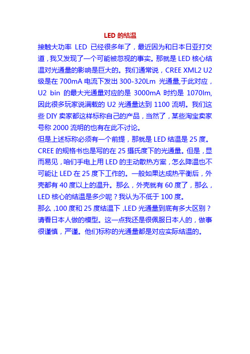
LED的结温接触大功率LED已经很多年了,最近因为和日本日亚打交道,我又发现了一个可能被忽视的事实。
那就是LED核心结温对光通量的影响是巨大的。
我们通常说,CREE XML2 U2级是在700mA电流下发出300-320Lm 光通量,于此对应,U2 bin 的最大光通量对应的是3000mA时约是1070lm,因此很多玩家说满载的U2光通量达到1100流明。
我们这些DIY卖家都这样标称自己的产品,当然了,某些淘宝卖家号称2000流明的也有在此不讨论。
但是上述标称必须有一个前提,那就是LED结温是25度。
CREE的规格书也是写的在25摄氏度下的光通量。
但是,显而易见,咱们手电上用LED的主动散热方案,怎么降温也不可能让LED在25度下工作的。
一般如果达成热平衡后,外壳都有40度以上的温升。
那么,外壳就有60度了,那么,LED核心的结温是多少呢?我认为不低于100度。
那么,100度和25度结温下,LED光通量到底有多大区别?请看日本人做的模型。
这一点我还是很佩服日本人的,做事很谨慎,严谨。
他们标称的光通量都是对应实际结温的。
请看上表是2种规格的LED,在25度结温时候,2000毫安电流下的光通量分别达到535和406流明。
再看下表,120度结温情况下的:在120摄氏度的结温的情况下,2000mA下最大光通量已经下降为431和328流明。
经过对比,我们可得知,在120度时候,2000mA电流下的光通量已经下降到25摄氏度的431/535*100%=81.3%, 328/406*100%=80.7%.因此,实际上,在手电上使用的时候,我们得到的光通量可能只有标称值得80%! 这一事实可能长期为大家忽视,标称1000流明的LED,最终使用时候可能只有800流明.以此类推.对比不同结温下的数值,也可以得到LED光通量和结温温度的线性关系,那就是其他条件相同时,核心结温越高,光通量越低.这让我们除了应该知道手电应该尽可能做好散热以延长LED寿命以外,我们还应知道,降低LED工作温度也可以提高光通量.这就是效率问题了.这个事是我在开发高显色手电时候发现的,为尽可能降低核心温度,我们在LED基板上努力挖掘了一下子,上了热电分离的基板.目前刚刚做了几千个,因为厂家下料时候搞错了,我定的20mm基板被他们给做成了铝的,而16mm就是铜的。
大功率LED灯珠1W 规格书英文版本
Customer:Description:Customer Service Hotline:400-676-8616TEL:0769-8200 5999 F AX:0769-8200 2227E-MIAL∶chenmo@ FeaturesApplicationsFeature of the device: Small packagewith high efficiencyTypical color temperature: 8500 K . Typical viewing angle: 140°Typical light flux outpu t : 110 LM @ 350m A . ESD protection.Soldering methods: SMTGrouping parameter: Luminous Flux,Forward Voltage and Chromaticity.Moisture Sensitivity Level: 3 Color rendering Index: 80(typ.) Thermal resistance(Junction to Heat sink): 15 °C /WThe product itself will remain within RoHScompliant.Design and effect illumination Interior automotive lighting(e.g. dashboard backlighting)Room lighting (e.g. luminaries, spotlights) Reading light (aircraft, car, bus) Signal and symbol luminariesMarker lights (e.g. steps, exit ways, etc.) Architectural illuminationMaterialsItemsDescriptionHousing black body Heat resistant polymer Encapsulating Resin Silicone resinElectrodes Ag plating copper alloy Die attach Silver paste ChipInGaNHigh Power LED – 1WTaiwan Togia Optoelectronics Technology Co., Ltd.Harsh environment optical efficiency: 72 lm / WHigh Power LED – 1W DimensionsNotes.1. Dimensions are in millimeters.2. Tolerances for fixed dimensions are ± 0.25mm.High Power LED – 1WMaximum Ratings (T Soldering =25ºC)Parameter Symbol Rating Unit DC Operating Current IF400 mAPulsed Forward Current(1)IPF500 mA ESD Sensitivity ESD 2000 VJunction Temperature Tj125 °COperating Temperature Top.-40 ~ +85 °CStorage Temperature Tstge.-40 ~ +100 °CJunction To Heat-Sink Thermal Resistance Rth 15 °C/WElectro-Optical Characteristics(T Soldering =25ºC)Parameter Symbol Min Typ. Max Unit ConditionLuminous Flux (2) Фv100 ..... 110 lmForward Voltage(3)V F---- 3.55 ---- VColor Temperature CCT 8000 ..... 9000 KI F=350mANote.1. tp 100µs, Duty cycle = 0.25≦2. Luminous Flux measurement tolerance: ±10%.3. Forward Voltage measurement tolerance: ±0.1V.Taiwan Togia Optoelectronics Technology Co., Ltd.High Power LED – 1WLuminous Flux Bin Table Group Bin Min Typ. Max1 1.5 ---- 3 23 ----4 3 4 ----5 4 5 ----6 E5 6 ---- 8 1 8 ---- 10 210 ---- 13 3 13 ---- 17 4 17 ---- 20 F5 20 ---- 23 1 23 ---- 27 227 ---- 33 3 33 ---- 39 4 39 ---- 45 J5 45 ---- 52 1 52 ---- 60 2 60 ----70 31 70 ---- 75 32 75 ---- 80 3380 ---- 85 41 85 ---- 90 42 90 ---- 95 43 95 ---- 100 51 100 ---- 110 52 110 ---- 120 K53120----130Group Bin Min Typ. Max11 130 ---- 140 12 140 ---- 150 13 150 ---- 160 21 160 ---- 180 22 180 ---- 200 31 200 ---- 225 32 225 ---- 250 41 250 ---- 275 42 275 ---- 300 51 300 ---- 350 N52 350 ---- 400 1 400 ---- 500 2 500 ---- 600 3 600 ---- 750 4 750 ---- 1000 R 51000----1300High Power LED – 1W Forward Voltage Bin TableGroup Bin Min Typ. Max1 1.75 ---- 1.852 1.85 ---- 1.95 U13 1.95 ---- 2.051 2.05 ---- 2.152 2.15 ---- 2.25 U23 2.25 ---- 2.351 2.35 ---- 2.452 2.45 ---- 2.55 U33 2.55 ---- 2.651 2.65 ---- 2.752 2.75 ---- 2.85 U43 2.85 ---- 2.95 Group Bin Min Typ. Max1 2.95 ---- 3.052 3.05 ---- 3.15 V13 3.15 ---- 3.251 3.25 ---- 3.352 3.35 ---- 3.45 V23 3.45 ---- 3.551 3.55 ---- 3.652 3.65 ---- 3.75 V33 3.75 ---- 3.851 3.85 ---- 3.952 3.95 ---- 4.05 V43 4.05 ----4.151 4.15 ---- 4.252 4.25 ---- 4.35V53 4.35 ---- 4.45 Group Bin Min Typ. Max1 4.45 ---- 5.02 5.0 ---- 5.53 5.5 ---- 6.04 6.0 ---- 6.55 6.5 ---- 7.06 7.0 ---- 7.5O7 7.5 ---- 8.01 8.0 ---- 9.02 9.0 ---- 10.03 10.0 ---- 11.0R4 11.0 ---- 12.0High Power LED – 1WWhite Binning StructureCool White0.240.280.320.360.400.44C I E -YC I E -XNote.This datasheet is a product series datasheet with a list of all possible rankings for the entire Everlight high power portfolio. It does not specify exact bins available for any particular package. Please contact a member of your regional Everlight branch to receive specific binning, exact order codes and individual datasheets for a particular high power LED.Taiwan Togia Optoelectronics Technology Co., Ltd.High Power LED – 1WCool-White Bin Coord inates4550BinCIE X CIE Y BinCIE X CIE Y 0.364 0.383 0.364 0.383 0.367 0.40.362 0.3720.348 0.385 0.346 0.359 U40.347 0.372U50.347 0.372Reference Range: 4500~5000K Reference Range: 4500~5000KBin CIE X CIE Y0.362 0.372 0.36 0.3570.344 0.344 U60.346 0.359Reference Range: 4500~5000K5056BinCIE X CIE Y BinCIE X CIE Y 0.329 0.357 0.329 0.345 0.329 0.3690.329 0.3570.348 0.385 0.347 0.372 V40.347 0.372V50.346 0.359Reference Range: 5000~5650KReference Range: 5000~5650KBin CIE X CIE YBin CIE X CIE Y0.329 0.331 0.329 0.331 0.329 0.3450.344 0.3440.346 0.359 0.343 0.331 V60.344 0.344V70.329 0.32Reference Range: 5000~5650K Reference Range: 5000~5650K 5663BinCIE X CIE Y BinCIE X CIE Y 0.329 0.369 0.329 0.345 0.329 0.3570.316 0.3330.315 0.344 0.315 0.344 W40.314 0.355W50.329 0.357Reference Range: 5650~6300KReference Range: 5650~6300KBin CIE X CIE YBin CIE X CIE Y0.329 0.345 0.329 0.331 0.329 0.3310.329 0.320.317 0.32 0.318 0.31 W60.316 0.333W70.317 0.32Reference Range: 5650~6300KReference Range: 5650~6300KHigh Power LED – 1WBinCIE X CIE Y 0.329 0.321 0.329 0.310.319 0.3 W80.318 0.31Reference Range: 5650~6300K6370BinCIE X CIE YBinCIE X CIE Y 0.301 0.342 0.305 0.322 0.314 0.3550.303 0.3330.315 0.344 0.315 0.344 X40.303 0.333X50.316 0.333Reference Range: 6300~7000KReference Range: 6300~7000KBin CIE X CIE YBin CIE X CIE Y0.308 0.311 0.308 0.311 0.305 0.3220.317 0.320.316 0.333 0.319 0.3 X60.317 0.32X70.311 0.293Reference Range: 6300~7000K Reference Range: 6300~7000K 7080BinCIE X CIE Y BinCIE X CIE Y 0.308 0.311 0.311 0.293 0.297 0.3000.302 0.2830.290 0.318 0.297 0.300 Y6-30.303 0.333Y9-30.308 0.311Reference Range: 7000~8000KReference Range: 7000~8000K 8090Bin CIE X CIE Y Bin CIE X CIE Y 0.289 0.291 0.295 0.276 0.281 0.3090.289 0.2910.290 0.318 0.297 0.300 Y6-20.297 0.300Y9-20.302 0.283Reference Range:8000~9000KReference Range: 8000~9000K 90100Bin CIE X CIE Y Bin CIE X CIE Y 0.283 0.284 0.290 0.270 0.274 0.3010.283 0.2840.281 0.309 0.289 0.291 Y6-10.289 0.291Y9-10.295 0.276Reference Range: 9000~10000KReference Range: 9000~10000KNote.1. X, Y color coordinates measurement tolerance: ±0.01.High Power LED – 1WRelative Spectral Distribution,I F =350mA, T Soldering =25ºC Forward Voltage vs Forward Current, T Soldering =25ºC Relative Luminous Intensity vs Forward Current, T Soldering =25ºCForward Current Derating Curve, Derating based on T j MAX =125°CTypical Electro-Optical Characteristics Curves4005006007008000.00.20.40.60.81.0R e l a t i v e L u m i n o u s I n t e n s t i yWavelength(nm)01002003004005002.62.83.03.23.43.63.8F o r w a r d V o l t a g e (V )Forward Current (mA)01002003004005000.00.20.40.60.81.01.21.4R e l a t i v e L u m i n o u s I n t e n s i t yForward Current (mA)20406080100100150200250300350400Soldering Temperature (oC )F o r w a r d C u r r e n t (m A )Taiwan Togia Optoelectronics Technology Co., Ltd.High Power LED – 1W-80-60-40-200204060800.00.10.20.30.40.50.60.70.80.91.0R e l a t i v e L u m i n o u s I n t e n s i t yDegree (2θ)Typical Representative Spatial Radiation PatternNote.1. 2θ1/2 is the off axis angle from lamp centerline where the luminous intensity is 1/2 of the peak value.2. Viewing angle tolerance is ± 10∘.Taiwan Togia Optoelectronics Technology Co., Ltd.High Power LED – 1WReliability DataStress Test Stress Condition Stress Duration Reflow Tsol=260℃, 10sec, 6min 3 timesThermal ShockH:+100℃20min.'∫ 10sec.'L:-10℃20min.300 CyclesTemperature Cycle H:+85℃30min.'∫ 5min.'L:-40℃30min.300 CyclesHigh Temperature/HumidityOperationTa=85℃ , RH=60%, IF=225mA 1000hoursRoom Temperature OperationLifeTa=25℃, IF=350mA 1000hoursHigh Temperature OperationLife #1Ta=55℃, IF=350mA 1000hoursHigh Temperature OperationLife #2Ta=85℃, IF=225mA 1000hoursLow Temperature OperationLifeTa=-40℃, IF=350mA 1000hours Failure Criteria:1. LEDs are open or shorted2. lm: luminous flux attenuate difference(1000hrs)>50%3. VF: forward voltage difference(1000hrs)>20%Taiwan Togia Optoelectronics Technology Co., Ltd.High Power LED – 1WPrecautions For UseOver-current-proofAlthough the EHP-AX08 series has a conductive ESD protection mechanism, customermust not use the device in reverse and should apply resistors for extra protection. Otherwise, slight voltage shifts may cause significant current change resulting in burn out failure.1. Storagei. Do not open the moisture proof bag before the devices are ready to use.ii. Before the package is opened, LEDs should be stored at temperatures less than 30℃and humidity less than 50%.iii. LEDs may be stored for 6 months. When the storage time has reached more than 6 months, LEDs should be stored in a sealed container filled with the Nitrogen gas.iv. After the package is opened, LEDs should be stored at temperatures less than 30℃and humidity less than 30%.v. LEDs should be used within 168 hours (7 days) after the package is opened.vi. Before using LEDs, baking treatment should be implemented based on the following conditions: pre-curing at 60±5℃for 24 hours.2. Thermal Managementi. For maintaining the high flux output and achieving maximum reliability, EHP-AX08series LEDs should be mounted on a metal core printed circuit board (MCPCB) or otherkinds of heat sink with proper thermal connection to dissipate approximately 1W ofthermal energy at 350mA operation.ii. Heat dissipation or thermal conduction design is strongly recommended on PCB or MCPCB for reflow soldering purposes. Please refer to soldering patterns on Page 2.iii. Sufficient thermal management must be implemented. Please refer to the graph “Forward Current Derating Curve “ on Page 9. The soldering temperature must be keptunder 60℃ at the driving current 350mA.Otherwise, the junction temperature of diemay exceed over the limit at high current driving conditions and the LEDs’ lifetime maybe decrease dramatically.iv. Special thermal designs are also recommended to take in outer heat sink design, such as FR4 PCB on Aluminum with thermal vias or FPC on Aluminum with thermalconductive adhesive, etc.v. Sufficient thermal management must be conducted, or the die junction temperature will be over the limit under large electronic driving and LED lifetime will decrease critically..High Power LED – 1W3. Proper HandlingTo avoid contamination of materials, damage of internal components, and shortening of LED lifetime, do not subject LEDs to conditions as those listed below.Bare HandTweezersWhen handling the product, do not apply direct pressure on the resin. Do not touch the resin to avoid scratching or other damage.Pick and Place Nozzle for Surface Mount Assembly.During Module AssemblyAvoid directly contacting the lens with nozzle. Do not stack the modules together, it could damage the resin or scratch the lens.High Power LED – 1W4. Soldering Ironi. For Reflow Processa. EHP-AX08 series are suitable for SMT process.b. Curing of glue in oven according to standard operation flow processes.c. Reflow soldering should not be done more than twice.d. In soldering process, stress on the LEDs during heating should be avoided.e. After soldering, do not warp the circuit board.ii. For Manual Soldering Processa. For prototype builds or small series production runs it is possible to place and solder theLED by hand.b. Dispense thermal conductive glue or grease on the substrates and follow its curingspecifications. Gently press LED housing to closely connect LED and substrate.c. It is recommended to hand solder the leads with a solder tip temperature of 280°C forless than 3 second, at a time with a soldering iron of less than 25W. Solder at intervals of two seconds or more.d. Take caution and be aware that damaged products are often a result of improper handsoldering technique.。
1W大功率发光二极管

1W大功率发光二极管(LED)的驱动电源鉴于大功率发光二极管工作电压仅为3V。
通过全桥整流将220V交流电变成直流电,在全桥上的电压降约为1.8V,只驱动一只发光二极管工作的电能利用效率仅为60%。
必须把3只以上发光二极管串联起来工作,才能使总的电能利用效率超过80%。
根据3基色合成白光原理,将红、绿、蓝3只1W大功率发光二极管串联起来工作,就可以获得相当于3W发白光的LED所达到的亮度。
同时还可以组合出6种彩色光线,满足人们对变换彩光的喜好。
为了避免电能浪费,使用市电做 LED驱动电源应采用电容器做降压限流元件。
其中:C3电容的主要作用是在刚接通220V市电时防止可能产出的瞬间大电流通过LED使其受到损坏,VS1可控硅则是防止负载开路时在C3两端产生高压使其严重发热爆炸。
VDS1触发二极管的转折电压为30V~40V,正常状况下C3两端电压不超过10V,VDS1一直截止。
VS1也截止。
只有在负载电路断掉或LED 内部开路情况下,C3两端电压刚升到30V~40V时VS1才即刻导通并维持导通状态。
排除故障重新接通电源,VS1即自动恢复截止状态。
如果只要求3只大功率LED-起发光,电源驱动电路中的VT1~VT9和R3~R9可全部不用。
该部分电路专门为控制红、绿、蓝3只LDE的发光状态而设计,A、B、C三端悬空或接到直流负端相对中点上,VT1、vT4、VT7~VT9截止,VT2、VT3、VT5、VT6导通,LED2和LED3分别被VT2和VT3短路,只有LED1工作发光。
单独将B端接到直流正端,将使VT8导通,VT5和、VT2随之截止,LED2工作发光。
单独将C端接到直流正端,将使VT9导通,VT6和VT3随之截止,LED3工作发光。
与此同时,B 端或C端接到直流正端,都可使VT4导通、VT1随之导通,LEDl被VT1短路不工作。
但将A端接到直流正端,将使VT7导通,强制让BG4截止,VT1随之截止。
LED1工作发光。
描述1W功率LED灯源说明书

Description1W Power LED Light Source is a high performance energy efficient device which can handle high thermal and high driving current. The exposed pad design has excellent heat transfer from the package to the motherboard. The Cool White Power LED is available in various color temperature ranging from 4000K to 10000K and Warm White Power LED ranging from 2600K to 4000K. The product has high Color Rendering Index (CRI) which provides excellent color perception and visual clarity.The low profile package design is suitable for a wide variety of applications especially where height is a con-straint.Applications• Portable (flash light, bicycle head light)• Reading light • Architectural lighting • Garden lighting • Decorative lightingASMT-MxA01W Power LED Light Source on MCPCBData SheetFeatures• Available in green, blue, cool white and warm white color.• Energy efficient • High current operation.• Long operation life.• Wide viewing angle.• Silicone encapsulationSpecifications• InGaN Technology • 3.6V, 350 mA (typical)• 120 viewing angleDevice Selection Guide at Junction Temperature T j = 25°CColorPart Number Luminous Flux, Φv [1, 2, 3] (lm)Test Current (mA)Dice Technology Min Typ Max Green ASMT-MGA025.540.073.0350InGaN Blue ASMT-MBA0 5.510.019.5350InGaN Cool White ASMT-MWA043.060.073.0350InGaN Warm WhiteASMT-MYA043.050.073.0350InGaNNotes:1. ΦV is the total luminous flux output as measured with an integrating sphere at 25ms mono pulse condition.2. Flux tolerance is ±10 %3. ΦVdata are only applicable for ASMT-Mx00 component level device only.Package DimensionsNOTES:1. ALL DIMENSIONS IN MILLIMETERS.2. TOLERANCE IS ±0.1MM UNLESS OTHERWISE SPECIFIED. Part Numbering SystemColor Bin SelectionMax Flux Bin SelectionMin Flux Bin SelectionColorB -BlueG -GreenW -Cool WhiteY -Warm WhiteAbsolute Maximum Ratings [3] at T A = 25°CParameter ASMT-MxA0UnitsDC Forward Current [1]350mAPeak Pulsing Current [2]500mAPower Dissipation1400mWLED Junction Temperature110°C Operating Ambient Temperature Range -40 to +85°C Storage Temperature Range-40 to +100°CNote:1. DC forward current – derate linearly based on Figure 5.2. Pulse condition duty factor = 10%, Frequency = 1kHz.3. Absolute Maximum Rating data are only applicable for ASMT-Mx00 component level device only. Optical Characteristics [3] (T A = 25 °C)Part Number Color Peak WavelengthλPEAK (nm)Dominant WavelengthλD[1] (nm)Viewing Angle2q½[2] (Degrees)Luminous Efficiency(lm/W) Typ.Typ.Typ.Typ.ASMT-MGA0Green51952512032 ASMT-MBA0Blue4604671208Part Number Color Correlated Color Temperature,CCT (Kelvin)Viewing Angle2q½ [2] (Degrees)Luminous Efficiency(lm/W) Min.Max.Typ TypASMT-MWA0Cool White40001000011048 ASMT-MYA0Warm White2600400011040Notes:1. The dominant wavelength, λD, is derived from the CIE Chromaticity Diagram and represents the color of the device.2. q½ is the off-axis angle where the luminous intensity is ½ the peak intensity.3. Optical Characteristics data are only applicable for ASMT-Mx00 component level device only.Electrical Characteristic [2] (T A = 25°C)Dice TypeForward VoltageV F (Volts) @ I F = 350mAReverse VoltageV R (Volts)Thermal ResistanceR q j-b (°C/W) [1] Typ Max.Max.Typ.InGaN 3.6 4.0518 Note:1. R q j-b is Thermal Resistance from LED junction to MCPCB.2. Electrical Characteristic data are only applicable for ASMT-Mx00 component level device only.Figure 4. Radiation PatternFigure 3. Relative Luminous Flux vs. Mono Pulse Current Figure 5. Maximum forward current vs. ambient temperatureDerated based on T J MAX = 110°C, R q JA = 30°C/W / 40°C/W and 50°C/WNote: All parametric charts are only applicable for ASMT-Mx00 component level device only.Figure 1. Relative Intensity vs. Wavelength Figure 2. Forward Current vs Forward VoltageFigure 6. Dominant wavelength vs. forward current – InGaN devices0.00.20.40.60.81.01.21.4050100150200250300350400450500MONO PULSE CURRENT - mAφV - R E L A T I V E L U M I N O U S F L U X - l m 0501001502002503003504000102030405060708090T A - AMBIENT TEMPERATURE - °CI F - M A X F O R W A R D C U R R E N T - mA100150200250300350400450500FORWARD VOLTAGE - VF O R W A R D C U R R E N T - m A450460470480490500510520530540100150200250300350400FORWARD CURRENT - mAD O M I N A N T W A VE L E N G T H - n mGREENBLUEWAVELENGTH - nm R E L A T I V E I N T E N S I T Y-90-70-50-30-101030507090OFF-AXIS ANGLE (°)R E L A T I V E I N T E N S I T YFigure 7. Chromaticity Shift vs. Current*Note: (x,y) values @ 350mA reference to (0.0)Figure 8. Temperature vs. relative forward voltage shiftFigure 9. Relative LOP vs. junction temperatureFlux Bin Limit [1] (For reference only) [x 1 x 2]Bin Flux (lm) at 350mAMin Max A 5.57.0B 7.09.0C 9.011.5D 11.515.0E 15.019.5F 19.525.5G 25.533.0H 33.043.0J 43.056.0K56.073.0Tolerance for each bin limits is ±10 %Note:1. Flux Bin Limit is only applicable for ASMT-Mx00 component level device onlyColor Bin LimitsBlue Min. (nm)Max. (nm)A 460.0465.0B 465.0470.0C 470.0475.0D475.0480.0Green Min. (nm)Max. (nm)A 515.0520.0B 520.0525.0C 525.0530.0D530.0535.0Tolerance = ±1nm00.01000.0010.0020.0030.0040.0050.0060.0070.008X COORDINATESY C O O R D I N A T E S-300-250-200-150-100-50050100150200250300-40-1510356085TEMPERATURE - °CR E L A T I V E F O R W A R D V O L T A G E S H I F T (m V )253035404550556065707580859095100105110JUNCTION TEMPERATURE (°C)R E L A T I V E L O P (%)Color Bin Selections [x3]Individual reel will contain parts from one full bin only.Cool White0Full DistributionA A onlyB B onlyC C onlyD D onlyE E onlyF F onlyG G onlyH H onlyZ A and B onlyY B and C onlyW C and D onlyV D and E onlyU E and F onlyT F and G onlyS G and H onlyQ A, B and C onlyP B, C and D onlyN C, D and E onlyM D, E and F onlyL E, F and G onlyK F, G and H onlyJ Special Color Bin1A, B, C and D only2E, F, G and H only3B, C, D and E only4C, D, E and F only5A, B, C, D and E only6B, C, D, E, and F only Warm White0Full DistributionA A onlyB B onlyC C onlyD D onlyE E onlyF F onlyZ A and B onlyY B and C onlyW C and D onlyV D and E onlyU E and F onlyQ A, B and C onlyP B, C and D onlyN C, D and E onlyM D, E and F onlyJ Special Color Bin1A, B, C and D only2E, F, G and H only3B, C, D and E only4C, D, E and F only5A, B, C, D and E only6B, C, D, E, and F onlyCool White Color Limits [1]Chromaticity CoordinatesBin A X Y 0.3670.4000.3620.3720.3290.3450.3290.369Bin B X Y 0.3620.3720.3560.3300.3290.3020.3290.345Bin C X Y 0.3290.3690.3290.3450.3050.3220.3010.342Bin D X Y 0.3290.3450.3290.3020.3110.2850.3050.322Bin E X Y 0.3030.3330.3070.3110.2830.2840.2740.301Bin F X Y 0.3070.3110.3110.2850.2900.2650.2830.284Bin G X Y 0.3880.4170.3790.3830.3620.3720.3670.400Bin HX Y0.3790.3830.3690.3430.3560.3300.3620.372Tolerances ± 0.01Note:1. Color Limit and Color binning chart are only applicable for ASMT-Mx00 component level device onlyWarm White Color Limits [1](Chromaticity Coordinates)Bin A X Y 0.4520.4340.4880.4470.4700.4140.4380.403Bin B X Y 0.4380.4030.4700.4140.4520.3840.4240.376Bin C X Y 0.4070.3930.4180.4220.4520.4340.4380.403Bin D X Y 0.3950.3620.4070.3930.4380.4030.4240.376Bin E X Y 0.3810.3770.3870.4040.4180.4220.4070.393Bin FX Y0.3730.3490.3810.3770.4070.3930.3950.362Tolerances ± 0.01X - COORDINATEY - C O O R D I N A T E0.340.360.380.400.420.440.460.480.500.52X - COORDINATEY - C O O R D I N A T ESub-Color Binning(Only Applicable for Color Bin A to Bin D and Bin G to Bin H)Cool White Color Limits (Chromaticity Coordinates)Bin A1X Y 0.3640.3830.3670.4000.3480.3850.3470.372Bin A2X Y 0.3640.3830.3620.3720.3460.3590.3470.372Bin A3X Y 0.3290.3570.3290.3690.3480.3850.3470.372Bin A4X Y 0.3290.3450.3290.3570.3470.3720.3460.359Bin B1X Y 0.3620.3720.3600.3570.3440.3440.3460.359Bin B2X Y 0.3600.3570.3580.3430.3430.3310.3440.344Bin B3X Y 0.3580.3430.3560.3300.3410.3140.3430.331Bin B4X Y 0.3290.3310.3290.3450.3460.3590.3440.344Bin B5X Y 0.3290.3310.3440.3440.3430.3310.3290.320Bin B6X Y 0.3430.3310.3410.3140.3290.3020.3290.320Bin C1X Y 0.3290.3690.3290.3570.3150.3440.3140.355Bin C2X Y 0.3290.3570.3290.3450.3160.3330.3150.344Bin C3X Y 0.3140.3550.3150.3440.3030.3330.3010.342Bin C4X Y0.3150.3440.3160.3330.3050.3220.3030.333Cool White Color Limits (Chromaticity Coordinates)Bin D1X Y 0.3290.3450.3290.3310.3170.3200.3160.333Bin D2X Y 0.3290.3310.3290.3200.3180.3100.3170.320Bin D3X Y 0.3290.3200.3290.3020.3200.2930.3180.310Bin D4X Y 0.3160.3330.3170.3200.3070.3110.3050.322Bin D5X Y 0.3170.3200.3180.3100.3090.3000.3070.311Bin D6X Y 0.3180.3100.3200.2930.3110.2850.3090.300Bin G1X Y 0.3920.4210.3860.4000.3640.3830.3670.400Bin G2X Y 0.3860.4000.3820.3850.3620.3720.3640.383Bin H1X Y 0.3820.3850.3780.3700.3600.3570.3620.372Bin H2X Y 0.3780.3700.3750.3580.3580.3430.3600.357Bin H3X Y0.3750.3580.3710.3440.3560.3300.3580.343Tolerances ±0.010.240.260.280.300.320.340.360.380.400.420.440.240.260.280.300.320.340.360.380.400.420.44X - COORDINATEY - C O O R D I N A T EDISCLAIMER: AVAGO’S PRODUCTS AND SOFTWARE ARE NOT SPECIFICALLY DESIGNED, MANUFACTURED OR AUTHORIZED FOR SALE AS PARTS, COMPONENTS OR ASSEMBLIES FOR THE PLANNING, CONSTRUCTION, MAINTENANCE OR DIRECT OPERATION OF A NUCLEAR FACILITY OR FOR USE IN MEDICAL DEVICES OR APPLI-CATIONS. CUSTOMER IS SOLELY RESPONSIBLE, AND WAIVES ALL RIGHTS TO MAKE CLAIMS AGAINST AVAGO OR ITS SUPPLIERS, FOR ALL LOSS, DAMAGE, EXPENSE OR LIABILITY IN CONNECTION WITH SUCH USE.Package Tray DimensionsHandling PrecautionThe encapsulation material of the product is made of silicone for better reliability of the product. As silicone is a soft material, please do not press on the silicone or poke a sharp object onto the silicone. These might damage the productand cause premature failure. During assembly or handling, the unit should be held on the body (white plastic).For product information and a complete list of distributors, please go to our web site: Avago, Avago Technologies, and the A logo are trademarks of Avago Technologies, Limited in the United States and other countries.Data subject to change. Copyright © 2007 Avago Technologies Limited. All rights reserved. AV02-0341EN - September 17, 2007。
1W的LED灯详解

LED的结温接触大功率LED已经很多年了,最近因为和日本日亚打交道,我又发现了一个可能被忽视的事实。
那就是LED核心结温对光通量的影响是巨大的。
我们通常说,CREE XML2 U2级是在700mA电流下发出300-320Lm 光通量,于此对应,U2 bin 的最大光通量对应的是3000mA时约是1070lm,因此很多玩家说满载的U2光通量达到1100流明。
我们这些DIY卖家都这样标称自己的产品,当然了,某些淘宝卖家号称2000流明的也有在此不讨论。
但是上述标称必须有一个前提,那就是LED结温是25度。
CREE的规格书也是写的在25摄氏度下的光通量。
但是,显而易见,咱们手电上用LED的主动散热方案,怎么降温也不可能让LED在25度下工作的。
一般如果达成热平衡后,外壳都有40度以上的温升。
那么,外壳就有60度了,那么,LED核心的结温是多少呢?我认为不低于100度。
那么,100度和25度结温下,LED光通量到底有多大区别?请看日本人做的模型。
这一点我还是很佩服日本人的,做事很谨慎,严谨。
他们标称的光通量都是对应实际结温的。
请看上表是2种规格的LED,在25度结温时候,2000毫安电流下的光通量分别达到535和406流明。
再看下表,120度结温情况下的:在120摄氏度的结温的情况下,2000mA下最大光通量已经下降为431和328流明。
经过对比,我们可得知,在120度时候,2000mA电流下的光通量已经下降到25摄氏度的431/535*100%=81.3%, 328/406*100%=80.7%.因此,实际上,在手电上使用的时候,我们得到的光通量可能只有标称值得80%! 这一事实可能长期为大家忽视,标称1000流明的LED,最终使用时候可能只有800流明.以此类推.对比不同结温下的数值,也可以得到LED光通量和结温温度的线性关系,那就是其他条件相同时,核心结温越高,光通量越低.这让我们除了应该知道手电应该尽可能做好散热以延长LED寿命以外,我们还应知道,降低LED工作温度也可以提高光通量.这就是效率问题了.这个事是我在开发高显色手电时候发现的,为尽可能降低核心温度,我们在LED基板上努力挖掘了一下子,上了热电分离的基板.目前刚刚做了几千个,因为厂家下料时候搞错了,我定的20mm基板被他们给做成了铝的,而16mm就是铜的。
统佳1W大功率LED规格书(通用)
Ver.1.0 Page: 2 of 6
光电特性曲线图
台湾统佳光电科技股份有限公司
TAIWAN TONGJIA OPTOELECTRONICS TECHNOLOGY CO.LTD
东莞市统佳光电科技有限公司
DONGGUAN TONGJIA OPTOELECTRONICS TECHNOLOGY CO., LTD
DONGGUAN TONGJIA OPTOELECTRONICS TECHNOLOGY CO., LTD
标准的最大参数
项目 正向电流 最大正向电流 峰值电流(1/10 工作周期,0.1ms 脉冲宽度) 反向压降(5V)
最大结温温度
应用温度 存储温度 抗人体静电(ESD)
符号
IF IFmax Ipulse
维持高于温度的时间:温度(TL) 维持高于温度的时间:时间(tL)
峰值/分类温度(TP) 在实际峰值温度(tp)5 度内的时间
降温速度 25 度升至峰值温度所需时间
铅基焊料
最高 3 度/秒 100 度 150 度
60-120 秒 183 度
60-120 秒 215 度 10-30 秒
最高 6 度/秒 最多 6 分钟
TAIWAN TONGJIA OPTOELECTRONICS TECHNOLOGY CO.LTD
东莞市统佳光电科技有限公司
DONGGUAN TONGJIA OPTOELECTRONICS TECHNOLOGY CO., LTD
特性
1、发光效率高 2、发光响应时间短、寿命长 3、环保、节能、低压驱动 4、耐热、耐湿、 5、光色纯、显色性高
3.6
3.8
V6
3.8
4.0
L3
80
天下明电源 1W 大功率 LED 驱动模块规格书
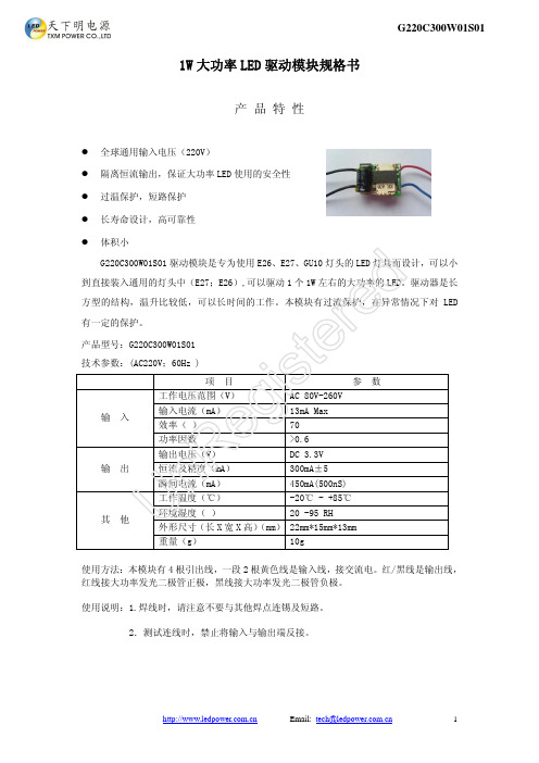
1W 大功率LED 驱动模块规格书────────────────────── Email: *****************.cn 1G220C300W01S01产 品 特 性l 全球通用输入电压(220V)l 隔离恒流输出,保证大功率LED 使用的安全性 l 过温保护,短路保护 l 长寿命设计,高可靠性 l 体积小G220C300W01S01驱动模块是专为使用E26、E27、GU10灯头的LED 灯具而设计,可以小到直接装入通用的灯头中(E27;E26),可以驱动1个1W 左右的大功率的LED。
驱动器是长方型的结构,温升比较低,可以长时间的工作。
本模块有过流保护,在异常情况下对LED 有一定的保护。
产品型号:G220C300W01S01 技术参数:(AC220V;60Hz )项 目参 数工作电压范围(V)AC 80V-260V 输入电流(mA) 13mA Max 效率(%) 70% 输 入功率因数>0.6 输出电压(V) DC 3.3V 恒流及精度(mA) 300mA±5% 输 出瞬间电流(mA) 450mA(500nS) 工作温度(℃) -20℃ - +85℃ 环境湿度(%)20%-95%RH 外形尺寸(长X 宽X 高)(mm) 22mm*15mm*13mm其 他重量(g)10g使用方法:本模块有4根引出线,一段2根黄色线是输入线,接交流电。
红/黑线是输出线,红线接大功率发光二极管正极,黑线接大功率发光二极管负极。
使用说明:1.焊线时,请注意不要与其他焊点连锡及短路。
2.测试连线时,禁止将输入与输出端反接。
Un Re gi st er ed。
高功率1W LED说明书
1W HI-POWER LED SPECIFICATIONHPM8-43KGAxHUEY JANN ELECTRONICS INDUSTRY CO.,LTD.No.27Line 466Sec.2,Canng-nan Rd.Wu-chi Town Taichung Shien,Taiwan,R.O.C.TEL:+886-4-26393976FAX:+886-4-26393125RoHSConformityHUEY JANN High Power1W LED is made of hi-eff AS/TS AlInGaP and GaInN chips with precise package technique which makes excellent heat dissipation to reach the advantages of high luminous efficiency,low decay,and long endurance.Now we have these colors available:red,green,blue,white, yellow and infrared.2FEATERUSØInstant lightØLong operating lifeØSuperior ESD defenseØLow voltage DC operatedØMore energy efficient than incandescent and most halogen lamps2TYPICAL APPLICATIONSØArchitectural detail lightingØPortable flashlightØReading lightsØMedical applicationsØLCD backlightsØBeacon lightsØDecoration lightsHUEY JANN ELECTRONICS INDUSTRY CO.,LTD.No.27Line466Sec.2,Canng-nan Rd.Wu-chi Town Taichung Shien,Taiwan,R.O.C.TEL:+886-4-26393976FAX:+886-4-263931252PACKAGE DIMENSIONS:1.All dimensions are in millimeter.2.Lead spacing in measured where the lead emerge from the package.3.prodruded resin under flange is 1.5mm max.4.specifications are subject to change without notice.5.Tolerance is +/-0.3mm unless otherwise noted.6.Driving LED without heat sinking device is forbidden.7.It is strongly recommended that the temperature of lead be not higher than 55oC.8.Proper current derating must be observed to maintain junction temperature below the maximum.9.LEDs are not designed to be driven in reserve bias.HUEY JANN ELECTRONICS INDUSTRY CO.,LTD.No.27Line 466Sec.2,Canng-nan Rd.Wu-chi Town Taichung Shien,Taiwan,R.O.C.TEL:+886-4-26393976FAX:+886-4-263931252ABSOLUTE MAXIMUM RATINGS*1.Duty Ratio=0.1%,Pulse Width=10us.*2.Iron soldering high temperature will not cause damage to the dice.But be aware of the high temperature will not only make the epoxy soften but also cause the lead moving and the gold wire broken and even open. So before returning to the normal temperatures PLEASE AVOID any serious pressure on the top of epoxy and lead.HUEY JANN ELECTRONICS INDUSTRY CO.,LTD.No.27Line466Sec.2,Canng-nan Rd.Wu-chi Town Taichung Shien,Taiwan,R.O.C.TEL:+886-4-26393976FAX:+886-4-263931252ELECTRIC-OPTICAL CHARACTERISTICSo*The dominate wavelength ,λd,is derived from the CIE Chromaticity Diagram and represents the color of the device.HUEY JANN ELECTRONICS INDUSTRY CO.,LTD.No.27Line 466Sec.2,Canng-nan Rd.Wu-chi Town Taichung Shien,Taiwan,R.O.C.TEL:+886-4-26393976FAX:+886-4-263931252RELIABILITY TEST*Failure Criteria:1.VF arise ≧10%2.IV decline ≧30%3.A failure is an LED that is open or shortedHUEY JANN ELECTRONICS INDUSTRY CO.,LTD.No.27Line 466Sec.2,Canng-nan Rd.Wu-chi Town Taichung Shien,Taiwan,R.O.C.TEL:+886-4-26393976FAX:+886-4-263931252RELIABILITY TEST*Failure Criteria:1.VF arise ≧10%2.IV decline ≧30%3.A failure is an LED that is open or shortedHUEY JANN ELECTRONICS INDUSTRY CO.,LTD.No.27Line 466Sec.2,Canng-nan Rd.Wu-chi Town Taichung Shien,Taiwan,R.O.C.TEL:+886-4-26393976FAX:+886-4-263931252.63.0 3.4 3.84.20140FORWARD VOLTAGE (V)F O R W A R D C U R R E N T (m A )F O R W A R D C U R R E N T (m A )AMBIENT TEMPERATURE( C)O4.670210280350-20 0 20 40 60 80 100 1200.20.41.0Ambient temperature( C)O R e l a t i v el u m i n o u s i t y1.201002003004005000.20.40.60.81.0R e l a t i v e l u m i n o u s i t yForward current (mA)1.20.60.81.42TYPICAL ELECTRICAL OPTICAL CHARACTERISTICS CURVESHUEY JANN ELECTRONICS INDUSTRY CO.,LTD.No.27Line 466Sec.2,Canng-nan Rd.Wu-chi Town Taichung Shien,Taiwan,R.O.C.TEL:+886-4-26393976FAX:+886-4-263931252TYPICAL ELECTRICAL OPTICAL CHARACTERISTICS CURVESHUEY JANN ELECTRONICS INDUSTRY CO.,LTD.No.27Line 466Sec.2,Canng-nan Rd.Wu-chi Town Taichung Shien,Taiwan,R.O.C.TEL:+886-4-26393976FAX:+886-4-26393125Forward Current Ta=25 CO-0.03-0.02-0.0100.01Cx0.030 200 400 600 800 1000WAVELENGTH (nm)R E L A T I V E R A D I A N T I N T E N S I T YTa=25 CO0.20.40.60.81.01.2470 520 570Ambient Temperature(C)o -0.012-0.010-0.004-0.0020.0020.0040.008-40 -20 0 20 40 60 80 100Cy0.02C h r o m a t i c i t y C o o r d i n a t eC h r o m a t i c i t y C o o r d i n a t e-0.008-0.00600.006Ta=25 COVIEW ANGLE 01020304050607080900.20.51/2 POWER0.81.02Brightness Bin SelectionNOTE:1.Test Condition at IF=350mA.HUEY JANN ELECTRONICS INDUSTRY CO.,LTD.No.27Line466Sec.2,Canng-nan Rd.Wu-chi Town Taichung Shien,Taiwan,R.O.C.TEL:+886-4-26393976FAX:+886-4-263931252Color Bin SelectionHUEY JANN ELECTRONICS INDUSTRY CO.,LTD.No.27Line466Sec.2,Canng-nan Rd.Wu-chi Town Taichung Shien,Taiwan,R.O.C.TEL:+886-4-26393976FAX:+886-4-263931252Package Dimension For Emitter TypeNOTE:1.Dimensions are specified as follows:mm.2.Tolerance is +/-0.3mm unless otherwise noted.3.50pcs emitters per tube.4.80tubes per inside box.5.4inside box per outsidebox.HUEY JANN ELECTRONICS INDUSTRY CO.,LTD.No.27Line 466Sec.2,Canng-nan Rd.Wu-chi Town Taichung Shien,Taiwan,R.O.C.TEL:+886-4-26393976FAX:+886-4-263931252Package Dimension For Star TypeNOTE:1.Dimensions are specified as follows:mm.2.Tolerance is +/-0.3mm unless otherwise noted.3.100pcs star per tray.4.10trays perbox.HUEY JANN ELECTRONICS INDUSTRY CO.,LTD.No.27Line 466Sec.2,Canng-nan Rd.Wu-chi Town Taichung Shien,Taiwan,R.O.C.TEL:+886-4-26393976FAX:+886-4-26393125Slug Independent2Requirements to user For Emitter typeThe LED products by HUEY-JANN is designed,manufactured,and sold aiming at high standard quality and reliability,however,reliability of electronic apparatus is seen as a product of reliability superior to HUEY-JANN and using status at users.From this point,HUEY-JANN requests user’s for following things.2Recommended Solder Pad Design For Emitter typeNote:1.All dimensions are in2.Electrical isolation is required between Slug and Solder Pad.HUEY JANN ELECTRONICS INDUSTRY CO.,LTD.No.27Line 466Sec.2,Canng-nan Rd.Wu-chi Town Taichung Shien,Taiwan,R.O.C.TEL:+886-4-26393976FAX:+886-4-263931252Heat Plate Soldering Condition For Emitter type a.Soldering Process for Solder PasteUse Solder Mask to print Solder Paste on PCB.Place Emitter on PCB.Put PCB on Heat Plate until Solder Paste melt.1.The Solder Paste sould be melted within 10seconds.2.Take out PCB out from Heat Plate within 15seconds.b.Soldering Process for Solder WirePut PCB on Heat Plate.Place Solder Wire to the solder pad of PCB.Put Emitter on PCB.Take the PCB out from Heat Plate within 10seconds.NOTE:1.Heat plate temperature:230oC max for Lead Solder and 260oC max for Lead-Free Solder.2.When soldering,do not put stress on the LEDs during heating.3.Aftersoldering,do not warp the circuit board.HUEY JANN ELECTRONICS INDUSTRY CO.,LTD.No.27Line 466Sec.2,Canng-nan Rd.Wu-chi Town Taichung Shien,Taiwan,R.O.C.TEL:+886-4-26393976FAX:+886-4-263931252Soldering Process For Hot Bar For Emitter TypeThermal Conductive Glue DispensingPut Emitter on the PCB.Hot Bar soldering of High Power EmitterNOTE:1.Hot Bar temperature:230oC max for Lead Solder and 260oC max for Lead-Free Solder.2.When soldering,do not put stress on the LEDs during heating.3.After soldering,do not warp the circuit board.2Manual Hand Soldering For Emitter TypePlace Thermal Conductive Glue on the PCB.Place Emitter on the e Soldering Iron to solder the leads of Emitter within 5seconds.1.Solder tip temperature:230°C max for Lead Solder and 260°C max for Lead-Free Solder.2.Avoiding damage to the emitter or to the PCB dielectric layer.Damage to the epoxy layer can cause3.Do not let the solder contact from solder pad to back-side of PCB.This one will causea short circuit and damage emitter.HUEY JANN ELECTRONICS INDUSTRY CO.,LTD.No.27Line 466Sec.2,Canng-nan Rd.Wu-chi Town Taichung Shien,Taiwan,R.O.C.TEL:+886-4-26393976FAX:+886-4-263931252ConclusionHuey Jann provide simple comparison table for High Power LED,you could find your request heat dissipation area from the following table.*TAB in this table is according to highest operating temperature 65C.*Different materials of second heat dissipation device,the surface area of heat sink will be different.Thus,this document is for reference only.HUEY JANN ELECTRONICS INDUSTRY CO.,LTD.No.27Line 466Sec.2,Canng-nan Rd.Wu-chi Town Taichung Shien,Taiwan,R.O.C.TEL:+886-4-26393976FAX:+886-4-263931252TAB Temperature -Life Characteristics Curves*Board Ambient Temperature Tolerance +/-5C.*TAB in this table is according to highest operating temperature 65oC.*The TAB is the stable testing value for the product lighted 100%after one hour.*Different materials of second heat dissipation device,the surface area of heat sink will be different.Thus,this document is for reference only.HUEY JANN ELECTRONICS INDUSTRY CO.,LTD.No.27Line 466Sec.2,Canng-nan Rd.Wu-chi Town Taichung Shien,Taiwan,R.O.C.TEL:+886-4-26393976FAX:+886-4-263931252Remarks:1.Brightness values are measured during a current pulse of typical25ms,thebrightness tolerance is+/-15%.2.Chromaticity coordinates are measured during a current pulse of typical200ms,thechromaticity tolerance is+/-0.015.3.Forward voltage are measured during a current pulse of typical5ms,the VF toleranceis+/-0.15V.4.Dimensions are specified as follows:mm.5.Related technical parameters of LED are average value resulted from statistic.Theactual parameters of LED could be slightly different from average and characteristic curve.6.The average value of LED will be changed by technical improvement and elevation,and subject to change without prior notice.7.Hi-Power LED can not be operated without second heat dissipating structure.8.Poor or damaged second heat dissipating structure could lead to defective electricalcharacteristic of High Power LED,CCT(Wavelength)escalation,brightness drop, lifetime shortening or burn out.Following instructions of Huey Jann Hi-Power LED series document can avoid LED burn out and electrical defectiveness due to improper usage,and maintain normal performance of the products.HUEY JANN ELECTRONICS INDUSTRY CO.,LTD.No.27Line466Sec.2,Canng-nan Rd.Wu-chi Town Taichung Shien,Taiwan,R.O.C.TEL:+886-4-26393976FAX:+886-4-26393125。
- 1、下载文档前请自行甄别文档内容的完整性,平台不提供额外的编辑、内容补充、找答案等附加服务。
- 2、"仅部分预览"的文档,不可在线预览部分如存在完整性等问题,可反馈申请退款(可完整预览的文档不适用该条件!)。
- 3、如文档侵犯您的权益,请联系客服反馈,我们会尽快为您处理(人工客服工作时间:9:00-18:30)。
y 0.3240 0.3364 0.3170 0.3160 0.3364 0.3395 0.3185 0.3170 0.3495 0.3755 0.3439 0.3285 0.3361 0.3524 0.3364 0.3240 0.3524 0.3705 0.3495 0.3364 0.3075 0.3820 0.3725 0.3495
动态温度循环
测试条件 焊接温度=300℃, 3 秒
0℃ ~~~ 100℃ 15 秒. 15 秒 -40℃ ~ 升温 ~ 120℃ ~ 降温 30 分钟 5 分钟 30 分钟 5 分钟 -40℃ ~ 升温 ~ 85℃ ~ 降温 18 分钟 42 分钟 18 分钟 42 分钟 IF=350mA,升降温的速率约为 3℃/min
0/50
0/22 0/22 0/22 0/22
0/22 0/22
无
失效标准
最小值
最大值
-
1.1 倍初始值
0.7
-
注意事项
1. 存贮
存贮条件: 打开包装之前,LEDs 应该存放在温度 25℃, 湿度 50%或更低条件下。LEDs 打开包装后应该在
12 小时内焊接完成,剩余未焊接 LEDs 应存放在防潮包装袋内,比如密封的带吸湿的容器内。建议把剩余 LEDs
向电压,在严重的情况下个别 LEDs 可能超过它能承受最大参数。
3.清洗
推荐使用酒精作为LED的清洗溶剂.。当用其他溶剂清洗前需要确定是否会损坏包装和硅胶。根据国际惯 例氟利昂不能用来作为清洗LEDs的溶剂,不要用超声波清洗LEDs,当确实需要用超声波清洗LEDs时,超声 波清洗LEDs的作用取决于例如超声波强度和相关条件等因素。在清洗之前, 需要提前试验以确定是否会给 LEDs带来任何损害.
高温存储
Ta= 110℃±0.5℃,RH=45%~65%
高湿存储
Ta=60℃±0.5℃,RH=85%±5%
低温存储
Ta=-40℃±2℃
常温常湿工作寿命 高温高湿稳态试验
低温工作寿命
Ta=25℃,RH=45%~65%, IF=350mA 基于标准电路板
Ta=85℃±2℃,RH=85%±5% IF=350mA 基于标准电路板
Ta=-40℃±2℃,IF=350mA
抗静电能力 ESD
1000V~4500V
*LED 热阻: Rja=8℃/W ~14℃/W
备注:
1.所有测试项目数据必须等到 LED 冷却后 1 小时测试; 2.失效标准: *电特性和光特性失效标准:
项目
符号
测试条件
正向电压
VF
IF=350mA
光通量
ΦV
IF=350mA
焊接时间 : ≤5 秒.
电光参数特性
(环境温度:25℃)
项目
符号
条件
最小 典型 最大 单位
正向电压
VF
IF=350[mA] 3.2
3.6
V
允许反向电流
IR
VR=5[V]
0
30
uA
光通量
Φv
IF=350[mA] 80
90
lm
波长
λD
IF=350[mA]
---
nm
色温
TC
IF=350[mA] 6000
6200
K
色区坐标
x
-
IF=350[mA]
y
-
IF=350[mA]
0.33 0.33
可视角
2θ1/2 IF=350[mA]
120
请参照色度图 CIE 1931
可视角允许误差 ±5%
档次
(环境温度:25℃)
项目
符号
条件
代码
最小 最大
单位
E
2.8
3.0
F
3.0
3.2
正向电压
G
3.2
3.4
VF
IF=350[mA]
V
H
3.4
3.6
I
3.6
3.8
J
3.8
4.0
60
60
70
70
70
80
光通量
Φv
IF=350[mA]
80
80
90
lm
90
90
100
100
100
120
正向电压测量允许误差 ±3%
光通量测量允许误差±10%
颜色档次
(正向电:350mA, 环境温度=25℃)
B7
B8
B9
C7
C8
C9
x 0.3057 0.3175 0.3193 0.3093 0.3175 0.3300 0.3300 0.3193 0.3300 0.3455 0.3436 0.3300 0.3032 0.3160 0.3175 0.3057 0.3120 0.3300 0.3300 0.3175 0.3300 0.3461 0.3455 0.3300
放回到原来的包装内。
LEDs 电极,支架,热沉全部是铜材质并且表面电镀银的,银在有腐蚀性的物质
环境下可能会受到污染而受到影响。因此请避免存放在会引起 LEDs 腐蚀,失去光泽,支架变色的环境下。LEDs
腐蚀或变色可能降低可焊接性或影响光学特性。LEDs 暴露在高温的有腐蚀性的环境中更可能会加快 LEDs 的
5. 散热
终端产品的散热设计格外重要。请考虑到 LEDs 的散热当设计系统时,LEDs 随电功率的输入温度系数的 增加是由电路板的热阻和 LEDs 在电路板上的密度和其原器件而决定的。因此必须避免大量集中散热并且严格 按照规格书上给定的参数来操作使用。请决定在使用通过每个 LEDs 的电流前考虑到当前环境温度并参考规格 书上的环境温度 vs.允许正向电流特性,同时要采取措施通过散去 LEDs 热沉周围的热量来提高 LED 的可操作 特性。
6. 其他
LEDs 发出足够强度的光可能损伤人眼,在没有戴眼罩的情况下不可直接观看 LEDs,眩光使人感到不舒服 因此在使用过程中可采取防范措施,同时也要采取必要的防护措施在使用由单个 LEDs 组装成的模块。更多信 息请联系销售人员。
4.静电
静电或浪涌电压会使 LEDs 失效。我们建议在使用 LED 时手带防静电手腕或防静电手套,所有的器件,设 备和机器必须接地,建议采取防范措施来防止设备产生的浪涌电压作用到 LED 上。当检验由单个 LEDs 组装成 成品时,建议检验每个 LEDs 是否引被静电破坏,检验可通过一指示灯测试或在一低电流下正向导通电压测试 (电流 20mA 最合适),已遭到破坏的 LEsD 表现为与正常 LEDs 不同的特性,比如说正向电压变的更低或在小电 流下不发光。
名 称:
外观图
单位 毫米 比例
公差 ±
外包装
备注: 1. 所有尺寸单位:MM. 2. 每个防静电盒内有 50 粒 emitters. 3. 三种卡通尺寸包装: 0.5k,1k,2k
内包装
型 号:
名 称:
包装图
单位: 毫米 比例: 1:1
可靠性项目和失效标准
可靠性测试项目:
测试项目 抗焊接温度
热震动 非工作冷热循环
腐蚀,同时请避免 LEDs 从不同的环境温度中快速的转移,尤其要注意不能在高湿环境下这可能引起收缩。
2.电路
在设计电路时通过每个 LEDs 的电流绝对不能超过最大参数.建议使用(B)电路来控制流过每个 LEDs 的
电流。同时在 A 电路中当用恒流源来驱动 LEDs 时,通过每个 LEDs 的电流可能要变化,这取决于每个 LEDs 的正
* 测试必须等到电路板冷却到环境温度。
备注 2次 20 次
100 次
1000 小时
1000 小时 1000 小时 1000 小时 1000 小时
1000 小时 1000 小时
失效标准 无 无
备注 2
备注 2
备注 2 备注 2 备注 2 备注 2
备注 2 备注 2
无
损坏数量 0/22 0/50
0/50
深圳伟兴光电科技有限公司
: 1W大功率LED
1. 绝对最大参数
(环境温度:25℃)
项目
符号
绝对最大参数
单位
正向电流
IF
350
mA
ห้องสมุดไป่ตู้脉冲电流
IFP
700
mA
允许反向电流
IR
10
uA
功率
PD
1
W
可操作温度
Topr
-40 ~ +85
℃
焊接温度
Tsod
手工焊接 ℃ 2 秒
脉冲电流条件 : 脉冲宽度≤10 毫秒. 占空比 ≤1/10
Tc
6200K-7000k
5500-6200
色区坐标误差: ±0.01 色温误差 :±10%
5000-5500
6200-7000
5500-6200
5000-5500
型 号:
名 称:
特性图
内部电路
条目 包装 封装材质 支架材质
物料 防静电包装盒 有机硅胶 铜基座表面镀银
型 号: 1W大功率LED
