1206双色贴片LED-1206贴片灯珠规格书
1206封装芯片LED(1.0毫米高度)说明书

Prepared date: 12-Aug.-2009
Rev 1
Page: 3 of 10
Prepared by: Changhong Pan
Bin Range Of Dom. Wavelength
Group
Bin
Min.
Max.
W
515
520
X
X
1000 Hrs. 22 PCS. 0/1
5
Low Temperature Storage
Temp. : -40℃
1000 Hrs. 22 PCS. 0/1
6 DC Operating Life
IF = 20 mA
1000 Hrs. 22 PCS. 0/1
7
High Temperature / High Humidity
telephone and fax. ․Flat backlight for LCD, switch and symbol. ․General use.
Device Selection Guide
PART No. 15-21/GHC-XS1T1/2T
Chip Material
InGaN
Emitted Color Brilliant Green
λd
515
-----
Spectrum Radiation Bandwidth
△λ
-----
35
Forward Voltage
VF
2.7
3.3
Reverse Current
IR
-----
-----
Max. 360 --------530 -----
3.7 50
Unit Condition
1206贴片灯珠参数

1206贴片灯珠参数摘要:1.1206 贴片灯珠概述2.1206 贴片灯珠参数列表3.参数详解3.1 长度与宽度3.2 厚度3.3 电流3.4 电压3.5 功率3.6 颜色3.7 发光效率3.8 视角3.9 工作温度与储存温度3.10 寿命正文:【1206 贴片灯珠概述】1206 贴片灯珠,又称1206LED 贴片灯珠,是一种采用贴片式封装的LED 灯珠。
它的尺寸为1.2mm×0.6mm,故名为1206。
这种灯珠具有体积小、重量轻、亮度高、能耗低等特点,广泛应用于各种照明产品和电子产品中。
【1206 贴片灯珠参数列表】以下是1206 贴片灯珠的主要参数:1.长度与宽度:1.2mm×0.6mm2.厚度:0.35mm3.电流:I=20mA~100mA4.电压:V=2.8V~3.4V5.功率:P=0.032W~0.12W6.颜色:红、橙、黄、绿、蓝、紫、白等7.发光效率:η=70~100lm/W8.视角:θ=15°~120°9.工作温度与储存温度:Ta=-40°C~+85°C,Ts=-40°C~+100°C10.寿命:L=50000h【参数详解】1.长度与宽度:1206 贴片灯珠的长度为1.2mm,宽度为0.6mm,这种小巧的尺寸使得它们非常适用于紧凑型设备和产品。
2.厚度:1206 贴片灯珠的厚度为0.35mm,同样体现了其轻薄的特点。
3.电流:电流范围为20mA 至100mA,根据实际应用需求,可以选择合适的电流值。
4.电压:电压范围为2.8V 至3.4V,这也是LED 灯珠的典型电压范围。
5.功率:功率范围为0.032W 至0.12W,这意味着1206 贴片灯珠具有较低的能耗。
6.颜色:1206 贴片灯珠有多种颜色可供选择,包括红、橙、黄、绿、蓝、紫、白等,适用于各种照明和显示需求。
7.发光效率:发光效率范围为70 至100lm/W,这使得1206 贴片灯珠具有较高的光效。
1206贴片led灯珠参数

1206贴片led灯珠参数1206贴片LED灯珠参数一、外观描述1206贴片LED灯珠是一种常见的表面贴装技术(Surface Mount Technology,SMT)组件,封装尺寸为12mm × 6mm。
它采用了贴片式封装,外观呈长方形,非常适合于在电子产品中进行紧凑型设计和布局。
二、光电参数1. 发光颜色:1206贴片LED灯珠可提供多种发光颜色,包括红、绿、蓝、黄、橙、紫等,以满足不同应用需求。
2. 发光强度:1206贴片LED灯珠具有较高的发光强度,能够提供明亮的光照效果,使其适用于各种照明和指示应用。
3. 视角:1206贴片LED灯珠具有特定的视角范围,常见的视角有120度、140度等,这决定了其在不同方向上的光照范围。
4. 亮度等级:1206贴片LED灯珠可以根据亮度等级进行分类,例如高亮度(High Brightness)LED、超高亮度(Ultra-High Brightness)LED等,以满足不同的照明和显示需求。
三、电气参数1. 工作电压:1206贴片LED灯珠的工作电压通常为2.0V至3.4V 之间,具体取决于所选用的LED芯片和发光颜色。
2. 工作电流:1206贴片LED灯珠的工作电流也是根据所选用的LED芯片和发光颜色而定,一般为5mA至20mA之间。
3. 反向电压:1206贴片LED灯珠具有一定的反向电压抗性,可以承受一定程度的反向电压,以保证其正常工作。
4. 静态电流:1206贴片LED灯珠在工作时会有一定的静态电流流过,这是由于材料内部的载流子流动引起的。
四、环境参数1. 工作温度:1206贴片LED灯珠的工作温度范围通常在-40℃至+85℃之间,适用于各种环境条件下的应用。
2. 存储温度:1206贴片LED灯珠的存储温度范围也是-40℃至+85℃之间,以确保其长期保存的稳定性和可靠性。
3. 抗静电能力:1206贴片LED灯珠具有一定的抗静电能力,可以在一定程度上防止静电对其产生不良影响。
1206高亮紫色LED芯片数据参数说明书

Technical Data SheetProduct Name:1206 High Bright Purple Chip LEDPart Number:HT15-2102UPCCustomer:Customer PN:Version No.: A.2Date:2009.01.01Customer ApprovalInstituted By:Checked By: Approved By:HARVATEK OPTO-ELECTRONICS (SHENZHEN) CO., LTD.TEL:*************FAX:*************Web:3. Soldering Profile Suggested3.1、For Lead Solder3.2、For Lead Free Solder4. Absolute Maximum Ratings At Ta=25℃Parameter Symbol Rating Unit Power Dissipation Pd 90 mWPeak Forward Current(1/10 Duty Cycle, 0.1ms Pulse Width)I FP100 mA DC Forward Current I F30 mA Reverse V oltage V R 5 V Operating Temperature Range Topr -30°C ~ + 85°C Storage Temperature Range Tstg -40°C ~ + 90°CSoldering Condition Tsol Reflow soldering : 260°C For 5 Seconds Hand soldering: 300°C For 3 Seconds5. Electrical Optical Characteristics At Ta=25℃Parameter Symbol Min. Typ. Max. Unit Test Condition Luminous Intensity IV --- 4 --- mcd IF = 20mA Viewing Angle 2θ1/2 --- 120 --- deg IF = 20mA Dominant Wavelength λd --- 408 --- nm IF=20mA Peak Wavelength λp --- 420 --- nm IF=20mA Spectral Line Half-Width Δλ--- 30 --- nm IF=20mA Forward V oltage VF 2.8 --- 3.6 V IF=20mA Reverse Current IR --- --- 10 uA VR=5VNotes: 1. Luminous intensity is measured with a light sensor and filter combination that approximates the CIE eye-response curve.2. θ1/2 is the off-axis angle at which the luminous intensity is half the axial luminous intensity.3. The dominant wavelength, λd is derived from the CIE chromaticity diagram and represents thesingle wavelength which defines the color of the device.11. Reliability TestClassification Test Item Test Condition Reference Standard Reference StandardOperation Life Ta= Under Room Temperature As PerData Sheet Maximum Rating1000HRS(-24HRS,+72HRS)*@20mAMIL-STD-750D:1026MIL-STD-883D:1005JIS C 7021:B-1High Temperature, High Humidity Storage IR-Reflow In-Board, 2 TimesTa= 65±5,RH= 90℃〜95%240HRS±2HRS MIL-STD-202F:103BJIS C 7021:B-11High Temperature Storage Ta= 105±5℃1000HRS(-24HRS,+72HRS)MIL-STD-883D:1008JIS C 7021:B-10EnduranceTestLow Temperature Storage Ta= -55±5℃1000HRS(-24HRS,+72H RS)JIS C 7021:B-12Temperature Cycling 105℃〜25℃〜-55℃〜25℃30mins 5mins 30mins 5mins10 CyclesMIL-STD-202F:107DMIL-STD-750D:1051MIL-STD-883D:1010JIS C 7021:A-4Thermal Shock IR-Reflow In-Board, 2 Times85 ± 5℃〜-40± 5℃℃10mins 10mins10 CyclesMIL-STD-202F:107DMIL-STD-750D:1051MIL-STD-883D:1011Solder Resistance T.sol= 260 ± 5℃10 ± 1secsMIL-STD-202F:210AMIL-STD-750D:2031JIS C 7021:A-1IR-Reflow Normal Process Ramp-up rate(183 to Peak) +3/ second max℃℃Temp. maintain at 125(±25) 120 seconds max℃Temp. maintain above 183 60℃-150 secondsPeak temperature range 235+5/℃-0℃Time within 5°C of actual Peak Temperature (tp)10-30 secondsRamp-down rate +6/second max℃--------MIL-STD-750D:2031.2J-STD-020CIR-Reflow Pb Free Process Ramp-up rate(217 to Peak) +3/ second max℃℃Temp. maintain at 175(±25) 180 seconds max℃Temp. maintain above 217 60℃-150 secondsPeak temperature range 260+0/℃-5℃Time within 5°C of actual Peak Temperature (tp)20-40 secondsRamp-down rate +6/second max℃--------MIL-STD-750D:2031.2J-STD-020CEnvironmentalTestSolderability T.sol= 235 ± 5℃Immersion rate 25±2.5 mm/secCoverage 95% of the dipped surface≧Immersion time 2±0.5secMIL-STD-202F:208DMIL-STD-750D:2026MIL-STD-883D:2003IEC 68 Part 2-20JIS C 7021:A-212. CautionsApplication1. A LED is a current-operated device. The slight shift of voltage will cause big change of current, whichwill damage LEDs. Customer should use resistors in series for the Over-Current-Proof.2.In order to ensure intensity uniformity on multiple LEDs connected in parallel in an application, it isrecommended to use individual resistor separately, as shown in Circuit A below. The brightness of each LED shown in Circuit B might appear difference due to the differences in the I-V characteristics of those LEDs.Circuit model A Circuit model B3.High temperature may reduce LEDs’ intensity and other performances, so keeping it away from heatsource to get good performance is necessary.Storage1.Before opening original package, it is recommended to store them in the following environment:Temperature: 5℃~30Humidity: 85%RH max.℃2. After opening original package, the storage ambient for the LEDs should be in 5~30°C temperature and60% or less relative humidity.3. In order to avoid moisture absorption, it is recommended that the LEDs that out of the original packageshould be stored in a sealed container with appropriate desiccant, or in desiccators with nitrogen ambient.4. The LEDs should be used within 168hrs (7 days) after opening the package. Once been mounted, solderingshould be quick.5. If the moisture absorbent material (silica gel) has faded away or the LEDs stored out of originalpackage for more than 168hrs (7 days), baking treatment should be performed using the conditions:60℃ at least 24 hours.ESD (Electrostatic Discharge )-ProtectionA LED (especially the Blue、White and Green product) is an ESD sensitive component, and staticelectricity or power surge will damage the LED. ESD-damaged LEDs will exhibit abnormal characteristics such as high reverse leakage current, low forward voltage, or “no light-up” at low currents, etc.Some advice as below should be noticed:1. A conductive wrist strap or anti-electrostatic glove should be worn when handling these LEDs.2. All devices, equipment, machinery, work tables and storage racks, etc. must be properly grounded.Harvatek Technical Data SheetPart No. : HT15-2102UPCVersionA.2 Issued date 2009.01.01 Page 10of 10 HARVA TEK OPTO-ELECTRONICS (SHENZHEN) CO., LTD. 3. Use anti-static package or boxes to carry and storage LEDs. And ordinary plastic package or boxes is forbidden to use.4. Use ionizer to neutralize the static charge during handling or operating.5. All surfaces and objects within 1 ft close to LEDs measure less than 100V .CleaningUse alcohol-based cleaning solvents such as IPA (isopropyl alcohol) to clean LEDs if necessary.Soldering1. Soldering condition refer to the draft “Soldering Profile Suggested ” on page 1.2. Reflow soldering should not be done more than 2 times.3. Manual soldering is only suggested on repair and rework. The maximum soldering temperature should not exceed 300°C within 3 sec. And the maximum capacity of soldering iron is 30W in power.4. During the soldering process, do not touch the lens at high temperature.5. After soldering, any mechanical force on the lens or any excessive vibration shall not be accepted to apply, also the circuit board shall not be bent as well.Others1. The LEDs described here are intended to be used for ordinary electronic equipment (such as office equipment, communication equipment and household applications).Consult Harvatek ’s Sales in advance for the applications in which exceptional reliability is required, particularly when the failure or malfunction of the LEDs may directly jeopardize life or health. (such as in aviation, transportation, traffic control equipment, medical and life support systems and safety devices).2. The light output from the high luminous intensity LEDs may cause injury to human eyes when viewed directly.3. The appearance and specifications of the product may be modified for improvement without prior notice.。
1206侧面发蓝光LED贴片发光二极管规格书
Page 2 of 5
MIL-STD-202G
JEITA ED-4701 200 203
JEITA ED-4701 200 201
JEITA ED-4701 200 202
JEITA ED-4701 100 103
JEITA ED-4701 300 302
JEITA ED-4701 300 303
JEITA ED-4701 300 304
LED LAMP
深圳市拓展光电有限公司
SHENZHEN TUOZHAN OPTOELECTRONICS CO.,LTD
SMDLED产品规格书
产品型号 : 文件编号 : 版本编号 :
06B2HC-c TZS-15-113B V.03
产品描述:
■ 1206SMD侧面发光高亮度LED ■ 胶体颜色: 透明 ■ 发光颜色:蓝光 ■ 半功率视角:---° ■ 无卡位 ■ 晶片材质: CaAsP
http://www.tzled.net
外形图:
R B
备注: 1. 所有尺寸单位为mm ,如无特殊说明误差范围为±0.02mm、支架长度误差范围0.02mm 。 2. 胶体沿支架延伸不可超过0.01mm。 3. 多胶不超过0.01mm。
Page 1of 5
产品应用:
1
指示
2 亮化
3
照明
最大限度性能参数(Ta = 25℃)
. 回流焊接
1206贴片发光管参数

1206贴片发光管参数
1206贴片发光管是一种常用的贴片LED产品,其参数通常包
括以下几个方面:
1. 尺寸:1206代表了该发光管的尺寸,尺寸为长12mm、宽
6mm。
2. 峰值波长:发光管的峰值波长决定了其发出的光的颜色,常见的有红色(620-635nm)、黄色(585-595nm)、绿色
(515-530nm)、蓝色(465-475nm)等。
3. 亮度:亮度是发光管发出的光的强度,通常用cd/m²(nit)
或者mcd等单位来表示。
4. 角度:角度表示了光线的发散程度,通常用度(°)来表示,常见的有120°,140°等。
5. 工作电流:发光管的工作电流通常用mA(毫安)来表示,
不同颜色的发光管有不同的工作电流要求。
6. 工作电压:发光管的工作电压通常用V(伏)来表示,不同颜色的发光管有不同的工作电压要求。
7. 灯光衰减:发光管的灯光衰减率表示了其寿命和稳定性,通常用小时(h)来表示。
需要注意的是,以上参数仅为一般情况下的参考值,实际产品的参数可能会根据生产厂家和产品型号的不同而有所变化。
贴片LED1206规格书

SEC.A-A
A
1.75 [0.07"]
0.20 [0.01"]
5.25 [0.21"]
8.00 [0.31"]
1.05 [0.04"] 4.00 [0.16"]
A
�
Arrangement of Tape
500 hrs
0/22
Low Temperature Life Test
1000 hrs
0/22
TAIWAN TONGJIA OPTOELECTRONICS TECHNOLOGY CO., LTD DONGGUAN TONGJIA OPTOELECTRONICS TECHNOLOGY CO., LTD
Test circuit and handling precautions
� Test circuit
+ -
R V
LED
� Handling precautions 1. Over-current-proof Customer must apply resistors for protection; otherwise slight voltage shift will cause big current change (Burn out will happen). 2. Storage 2.1 It is recommended to store the products in the following conditions: Humidity: 60% R.H. Max. Temperature : 5℃~30℃(41℉~86℉) 2.2 Shelf life in sealed bag: 12 month at <5℃~30℃ and <30% R.H. after the package is Opened, the products should be used within a week or they should be keeping to stored at≦20 R.H. with zip-lock sealed. 3. Baking It is recommended to baking before soldering when the pack is unsealed after 72hrs. The Conditions are as followings: 3.1 60±3℃ x(12~24hrs) and <5%RH, taped reel type 3.2 100±3℃ x(45min~1hr), bulk type 3.3 130±3℃ x(15~30min), bulk type
深圳市成兴光电子科技有限公司 1206带透镜30度黄色贴片式发光二极管产品说明书

产品承认书产品名称:1206带透镜30度黄色贴片式发光二极管产品型号:XL-TD3216UYC客户名称:客户料号:承认日期:深圳市成兴光电子科技有限公司制定审核核准客户承认栏确认审核核准一、产品描述:●外观尺寸(L/W/H ): 3.2x 1.6x 1.96mm●颜色:高亮度黄色●胶体:透明胶体●EIA 规范标准包装●环保产品,符合ROHS 要求●适用于自动贴片机●适用于回流焊制程二、外形尺寸及建议焊盘尺寸:备注:1.2.单位公差:毫米(mm):如无特别标注则为±0.10mC athode 推荐焊盘尺寸A node三、建议焊接温度曲线:有铅制程无铅制程四、最大绝对额定值(Ta=25℃):参数符号最大额定值单位消耗功率Pd55mW最大脉冲电流(1/10占空比,0.1ms脉宽)I FP100mA正向直流工作电流I F25mA 反向电压V R5V 工作环境温度Topr-30°C~+85°C存储环境温度Tstg-40°C~+90°C焊接条件Tsol 回流焊:260°C,10s 手动焊:300°C,3s五、光电参数(Ta=25℃):参数符号最小值代表值最大值单位测试条件光强IV160---240mcd IF=5mA 半光强视角2θ1/2---30---deg IF=5mA 主波长λD588---590nm IF=5mA 正向电压VF 1.9--- 2.1V IF=5mA 反向电流IR------1uA VR=5V 亮度分档:代码最小值最大值单位测试条件N2160240mcd IF=5mA电压分档:代码最小值最大值单位测试条件F3 1.9 2.1V IF=5mA波长分档:代码最小值最大值单位测试条件TY02588590nm IF=5mA六、光电参数代表值特征曲线:φ6七、标签标识:CAT:光强(mcd)HUE:波长(nm)REF:电压(V)误差范围a.Luminous Intensity:±15%b.HUE:±1nmc.Forward Voltage:±0.1V八、包装载带与圆盘尺寸:φ13.0AU ser Feed D irectionA A-A剖面图备注:1.单位:毫米(mm)2.公差:如无特别标注则为±0.15mm九、圆盘及载带卷出方向及空穴规格:尾端至少160mm盖带和空壳载带的组合开始端装有零件部分至少160mm盖带和至少160mm独立盖带或空壳载带的组合盖带与空壳载带的组合十、内包装及外包装:内标签圆盘干燥剂防潮防静电袋5cartons/box外标签抽真空、热封10bags/carton十一、信赖性实验:测试项目测试条件测试次数参考标准失效判定标准失效LED数量(PCS)防潮等级1.回流焊最高温度=260℃,10秒,2次回流焊;2.回流焊之前存储条件:30℃,相对湿度=70%,168H;-JEITAED-4701300301﹟10/22焊接信赖性(无铅回流焊)回流焊最高温度=245±5℃,5秒(无铅回流焊)-JEITAED-4701303303A﹟20/22冷热循环-40℃30分钟~25℃5分钟~100℃30分钟~25℃5分钟300个循环JESD22-A104﹟10/22冷热冲击-35℃15分钟转换时间3分钟85℃15分钟300个循环JESD22-A106﹟10/22高温存储Ta=100℃1000小时JESD22-A103﹟10/22低温存储Ta=-40℃1000小时JESD22-A119﹟10/22常温老化Ta=25℃IF=20mA1000小时JESD22-A108﹟10/22(2)失效标准标准﹟项目测试条件失效标准﹟1正向电压(V F)I F=20mA>U.S.L*1.1光强(IV)I F=20mA<L.S.L*0.7反向电流(I R)V R=5V>U.S.L*2.0﹟2焊接可靠性/锡膏覆盖焊盘比例小于95%★U.S.L:规格上限L.S.L:规格下限十二、使用注意事项:◆使用:1.过高的温度会影响LED的亮度以及其他性能,所以为使LED有较好的性能表现,应将LED远离热源。
贴片压敏电阻1206封装参数型号规格书大全
T2
20 uS 1000 uS
Characteristic
Test method and description
The specimen shall be subjected to 125℃ for 1000 hours in a thermostatic bath without High Temperature Storage load and then stored at room temperature and humidity for 1 to 2 hours. The change of
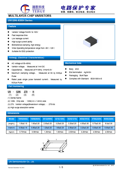
MULTILAYER CHIP VARISTORS
UN1206-XXXH Series
Feature
Varistor Voltage from5V to 100V Fast response time Low leakage current High surge current ability Bidirectional clamping, high energy Wide Operating temperature range from -55℃-125℃ Suitable for ESD protection
Dimensions
Model 1005(0402) 1608(0603) 2012(0805) 3216(1206) 3225(1210) 4532(1812) 5750(2220) 8050(3220)
Length(L) Width(W) High(H)
1.00±0.15 0.50±0.15 0.70max
Notes@(Electrical Characteristics)
AC voltage at 50~60Hz Varistor voltage: Measured at 1mA DC Capacitance: Measured at f=1MHz, Vrms=0.5V Maximum clamping voltage : Measured at 5A by 8/20µs
1206贴片led灯珠使用说明书

1206贴片led灯珠使用说明书1206贴片LED灯珠使用说明书在定购1206贴片LED灯珠时,经常出现使用过程中因为操作不当会出现死灯等问题,拓展LED为了客户更好的使用产品,整理了以下使用说明供大家参考:1. 物料确认投料的LED BIN 等级是否吻合。
例如:电压CIE BIN 亮度等参数是否属于同一等级,同一等级的应该在一起用。
正负极性是否符合需求,不同脚位发光是否符合要求。
若不是同一等级的LED应用在同一物件上,应先评估其适用性。
(若不同的电压BIN 在一起使用亮度可能有差异,不同的CIE BIN 在一起使用发光颜色可能会用差异)。
2. 1206贴片led灯珠包装储存:开包装前避免湿气进入LED 内部,建议SMD 系列的LED 存放在内置干燥剂的干燥柜中。
储存环境温度范围5-30 度,湿度不超过50%。
3.1206贴片led灯珠开包装后的预防措施开包装后尽可能采取整卷除湿措施除湿条件:70 度烘烤4-12 小时。
除湿后的材料应该尽快使用完(24 小时内)。
余料请密封或放置在10-40 度,湿度不超过30%的环境中。
4.1206贴片led灯珠作业注意事项本产品最多只可回焊两次,且在首次回焊后须冷却至室温之后方可进行第二次回焊.建议回流焊温度范围在200-240 度。
在作业过程中,不能用手直接取材料,手上有汗,汗水对硅胶表面存在光学污染,影响出光。
另外硅胶相对柔软,手用力挤压会导致断线造成死灯。
不建议将LED 贴装在弯曲的线路板上。
焊接时避免快速冷却,在LED 焊接冷却过程中避免任何形式的机械力或过度震动,焊接后,不要弯曲线路板。
在返修或单颗材料作业时,不能用镊子挤压胶体表面,由于硅胶相对较软,用镊子挤压胶体会导致断线,压伤晶片,从而死灯。
在批量作业时,吸嘴小于产品内径会导致吸嘴冲压硅胶,造成金线断裂,晶片受压而死灯。
完成焊接的LED 不宜进行返修作业,如不可避免,采用双头烙铁,但事先要确认返修后是否对LED特性产生破坏。
1206侧面发红光LED贴片灯珠规格书

试验条件
-40℃~25℃~100℃~25℃ 30分钟 5分钟 30分钟 5分钟
-40℃~100℃ 15分钟 15分钟
30℃~65℃ RH=90% 24小时/1回合
持续时间 取样数
循环100回 合
100
循环300回 合
100
循环50回合 100
接收 水准 0/100
1000小时
100
Ta=-30℃
IF=20mA(R,G,Y)/15mA(W,B)
1000小时
100
Tsol=260℃±5℃,10秒 离胶体3mm距离
焊接一次
20
Tsol=235℃±5℃,5秒 使用助焊剂
焊接一次
20
人体放电模式1000V
正反向各3 次
10
20G 20-2000HZ 4分钟 每个方向循
预热时间 = 100s 最大
预热时间 = 100s 最大.
温度下降斜率为 6ºC/s 最大
温度下降斜率为 6ºC/s 最大
峰值温度 = 230ºC 最大
峰值温度 = 250ºC 最大
在峰值温度±5℃时间不能超过10s 在峰值温度±5℃时间不能超过10s
超过183℃的温度的时间不能超过80s.超过 217℃的温度的时间不能超过80s.220-230℃之间不超过30s,230-240℃不超过20s.
6) 色座标X、Y的测量公差为±0.015。 7) 可靠性试验标准,请参阅“可靠性测试”。 8) 对于如何安全使用“ 拓展光电”的产品,请参阅“使用说明”。 9) 包装:1000PCS/包,普通包装 10)我们一直在不断努力,以改善LED产品的性能,规格如有变更,恕不另行通知。
GBD-C150KSKT-DZ 1206贴片式发光二极管说明书
本产品主要作为信号指示及照明的电子元件广泛应用于各类使用表面贴装结构的电子产品中,如家用电器的开关指示灯、手机键盘灯、汽车仪表盘照明等。
本产品也广泛用作液晶显示屏(LCD )的背光源。
This product is generally used as indicator and illumination for electronic equipment such as household appliance,communication equipment,and dashboard.And it can also be used as flat backlight for Liquid Crystal Display (LCD).特性:Features:管芯材料:AlGaInP Material:AlGaInP发光颜色:黄色Emitting Color:Yellow光强高,功耗低High Luminous Intensity and Low Power Dissipation 可靠性高,寿命长Good Reliability and Long Life 符合欧盟公布的RoHS 指令要求Complied With RoHS Directive目录Catalogue电性参数Electrical Characteristics 典型特性曲线Typical Characteristic Curves 可靠性实验Reliability Test Items And Conditions 外形尺寸Outline Dimensions 包装Packaging 焊接指导Guideline for Soldering 使用注意事项Precautions GBD-C150KSKT-DZ1206贴片式发光二极管1206Chip Light Emitting Diode技术数据表Technical Data Sheet...............................................................................................................................2.......................................................................................................................3...........................................................................................................4.........................................................................................................................................5.........................................................................................................................................................6..................................................................................................................................8. (10)✧极限参数(温度=25℃):Absolute Maximum Ratings (Temperature=25°C):*注:脉冲宽度≤0.1ms ,占空比≤1/10*Note:Pulse width ≤0.1ms,Duty ≤1/10✧光电参数(温度=25℃):Electro-Optical Characteristics (Temperature=25°C):电性参数Electrical Characteristics典型特性曲线Typical Characteristics Curves*1失效判断标准Criteria For Judging Damage可靠性试验Reliability Test Items And Conditions推荐焊盘图:Suggest Soldering Pad Dimensions :外形尺寸Outline Dimension✧载带CarrierTape单位:mm ,未注公差:±0.1mmAll dimensions in mm,tolerances unless mentioned is ±0.1mm.✧编带细节Details Of Carrier Tape前进方向 ProgressiveDirectionA :盖带,300mm ;B :引导,空带,200mm ;C :编载产品3000只;D :尾部,空带,200mm A:Top Cover Tape,300mm;B:Leader,Empty,200mm;C:3000Lamps Loaded;D:Trailer,Empty,200mm.✧带盘Reel Dimension前进方向 ProgressiveDirection包装(1)Packaging (1)✧ 防潮抗静电包装Moisture Proof and Anti-Electrostatic Foil Bag✧ 外包装箱Cardboard Box✧ 标签说明Label ExplanationType :产品型号LOT NO :批号Lot NumberQTY :数量QuantityREF :正向电压范围Forward Voltage RangeHUE :波长范围Wavelength Range CAT :光强范围Luminous Intensity Range包装(2)Packaging (2)1.使用烙铁人手焊接Hand Soldering推荐使用功率低于20W 的烙铁,焊接时烙铁的温度必须保持在300℃以下,且每个电极只能进行一次焊接,每次焊接的持续时间不得超过3秒。
1206双色LED-1206贴片LED灯珠规格参数

Customer confirm Approved by Checked by
Issued by
Part No. Emitted Color Chip Material
Amber AlGaInP
XGS-PB3216AMUB-04
Blue
Len's Color Water Clear
InGan
--
--
20
0/1
Connect with a power IF=20mA
5
Operating Life Test
Ta=Under room temperature
20
0/1
Test time=1000HRS(-24HRS,+72HRS)
6
Thermal Shock
-40±5℃→100±5℃ (15min,15min) 100 Cycles
e 460 465 475
Amber -- 120 --
2θ1/2
Deg. IF =5mA
Blue -- 120 --
Notes: 1.Tolerance of Luminous Intensity ±10%
2.Tolerance of Dominant Wavelength ±2nm 3. Tolerance of Forward Voltage ±0.05V 4. Luminous Intensity is measured by WENRUN’s equipment on bare chips
20
0/1
3
High Temperature And Ta:85±5℃,RH:85±5%,IF=20 High Humidity Working Test time=500HRS(-24HRS,+72HRS)
贴片led灯珠型号对照表,led贴片灯珠型号一览表都在这里!
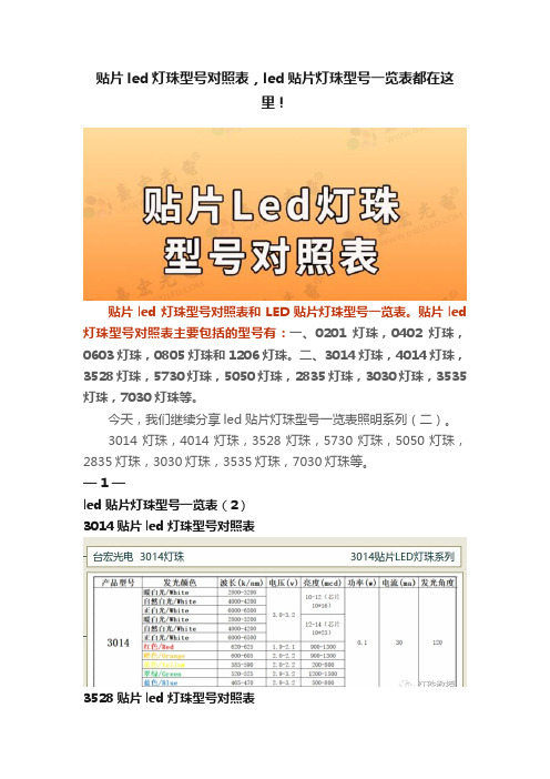
贴片led灯珠型号对照表,led贴片灯珠型号一览表都在这里!贴片led灯珠型号对照表和LED贴片灯珠型号一览表。
贴片led 灯珠型号对照表主要包括的型号有:一、0201灯珠,0402灯珠,0603灯珠,0805灯珠和1206灯珠。
二、3014灯珠,4014灯珠,3528灯珠,5730灯珠,5050灯珠,2835灯珠,3030灯珠,3535灯珠,7030灯珠等。
今天,我们继续分享led贴片灯珠型号一览表照明系列(二)。
3014灯珠,4014灯珠,3528灯珠,5730灯珠,5050灯珠,2835灯珠,3030灯珠,3535灯珠,7030灯珠等。
— 1 —led贴片灯珠型号一览表(2)3014贴片led灯珠型号对照表3528贴片led灯珠型号对照表3020&2016贴片led灯珠型号对照表3535贴片led灯珠型号对照表5730贴片led灯珠型号对照表335侧发灯珠3010侧发灯珠以上这些,都是我们比较常用的3014系列贴片LED灯珠型号规格参数。
3528贴片led灯珠参数一览表:(单色,双色,三色全彩)5730灯珠型号参数一览表(白光,彩光系列)其它:像4014,3030,5630,7030灯珠这些型号,因为参数和接近尺寸的功率,电流电流参数都差不多,所以,就没有特别列举。
更多的型号参数一览表,每个常用的型号都有。
如果你有具体的型号,可以直接咨询索取。
比如:像020侧发光灯珠,因为功率较小,现在慢慢地被3014侧发光系列取代,是因为3014侧发灯珠功率可以做0.1W,0.2W。
所以,一般对侧发功率较高的用户,也会优先选择3014侧发灯珠,亮度高,尺寸也相对较小。
总的来说贴片led灯珠型号对照表,给大家主要也是做一个参考的作用,其实这些款的型号规格参数相差不是很大,主要是功率,亮度和尺寸的差别。
很多工程师和采购用户,也会根据部分型号,咨询LED灯珠厂家。
这样,大家在新品选型或者找替代以前LED灯珠型号时,会有更好的选择。
PT1206BS 光敏三极管产品说明书

产品说明书1206贴片NPN光敏三极管PT1206BS ⏹描述PT1206BS是一款高速高灵敏度小型贴片NPN型光敏三极管1206封装,采用黑色环氧材料封装,产品适用于红外线的感光。
⏹特点●快速响应●高感光灵敏度●无铅环保●符合RoHS和REACH标准⏹应用●微型开关●计数器和分拣机●位置传感器●编码器●红外传感应用系统发射集集电极集电极标识建议回流焊焊盘尺寸注: 1. 所有尺寸单位位毫米(括号内单位为英寸) 2. 未标明误差的精度为± 0.2毫米(.008英寸) 3. 建议的焊盘尺寸仅供参考 请根据实际需要进行修改⏹封装尺寸⏹极限参数(Ta=25℃)参数名称符号参考值单位集电极-发射极电压V CEO 30V 发射极-集电极电压V ECO 5V 集电极电流Ic 20mA 焊接温度*1Tsol 260℃工作温度Topr -20~+85℃存储温度Tstg-40~+85℃说明:*1:焊接时间≦5seconds.Ambient Temperature Ta(°C)C o l l e c t o r P o w e rD i s s i p a t i o n (m W )40100020406080100-20-406080201008060200600Wavelength(nm)R e l a t i v e S p e c t r a l S e n s i t i v i t y (%)Ta=25°40700800900100011001200⏹光电参数(Ta=25℃)参数名称符号最小典型最大单位测试条件频谱范围λ0.5730--1100nm 感光峰值波长λP --940--nm 集电极–发射极击穿电压BV CEO30----V Ic=100μA,Ib=0发射极-集电极击穿电压BV ECO5----V Ic=100μA,Ib=0集电极暗电流I CEO ----100nA V CE =20V,H=0mw/cm2集电极-发射极饱和电压V CE (S )---0.4V Ic=2mA,I B =100μA 集电极电流I C (on)0.10.6--mAEe=1mW/cm2,V CE =5V 直流电流放大倍数H FE 1000--1800V CE =5V,IC=2mA 上升/下降时间t r /t f--15/15μS V CE =5V,I C =1mA R L =1000Ω⏹特性曲线图图.1集电极耗散功率与环境温度图.2相对频谱灵敏度300Ambient Temperature Ta(°C)R e l a t i v e C o l l e c t o r C u r r e n t (%)40608060100160Vce=5V204080120140Ee=1mW/cm 21020507025Ambient Temperature (°C)C o l l e c t o rD a r k C u r r e n t IC E O(n A )50751000.1110100Vce=20V 0.1Irradiance Ee(mW/cm )C o l l e c t o r C u r r e n t I c (m A )1100.01101010101010-1-2-3Vce=5VT =25 Ca °20Collector-Emitter Voltage V CE (V)C o l l e c t o r C u r r e n t I c (m A )12340.51.01.52.02.53.03.5Ee=0.5mW/cm2Ee=0.75mW/cm2Ee=1.0mW/cm2Ee=1.25mW/cm2Ee=1.5mW/cm2图.3相对集电极电流与环境温度图.4集电极电流与辐照度图.5集电极暗电流与环境温度图.6集电极电流与集射电压注: 1. 所有尺寸单位为毫米(英寸)发射极集电极注: 1. 所有尺寸单位为毫米(英寸)2. 未注明误差的尺寸为 ± 0.1mm(.004")⏹包装尺寸图⏹载带尺寸图(数量:3000个/盘)注意事项:1.我公司保留更改产品材料和以上说明书的权利,更改以上产品说明书恕不另行通知。
1206 电阻通用规格书
o d u c t s p e c i f i c a t i o n – F e b r u a r y 6, 2013 V .5S u p e r s e d e s D a t e o f M a r . 06, 2003Y A G E O B R A N D o r d e r i n g c o d eGLOBAL PART NUMBER (PREFERRED )RC1206 X R - XX XXXX L(1) (2) (3) (4) (5) (6)(1) TOLERANCED = ±0.5% F = ±1%J = ±5% (for Jumper ordering, use code of J)(2) PACKAGING TYPER = Paper taping reel(3) TEMPERATURE COEFFICIENT OF RESISTANCE– = Base on spec(4) TAPING REEL07 = 7 inch dia. Reel 10 = 10 inch dia. Reel 13 = 13 inch dia. Reel(5) RESISTANCE VALUEThere are 2~4 digits indicated the resistor value. Letter R/K/M is decimal point, no need to mention the last zero after R/K/M, e.g.1K2, not 1K20.Detailed resistance rules show in table of “Resistance rule of global part number”.(6) DEFAULT CODELetter L is system default code for order only (Note)ORDERING INFORMATION - GLOBAL PART NUMBER & 12NC Both part numbers are identified by the series, size, tolerance, packing type, temperature coefficient, taping reel and resistance value.SCOPEThis specification describes RC1206 series chip resistors with lead-free terminations made by thick film process.APPLICATIONS● All general purpose applicationFEATURES● Halogen Free Epoxy●RoHS compliant- Products with lead freeterminations meet RoHS requirements- Pb-glass contained in electrodes,resistor element and glass are exempted by RoHS●Reducing environmentally hazardous wastes●High component and equipment reliability● Saving of PCB space●None forbidden-materials used in products/productionO RDERING EXAMPLEThe ordering code of a RC1206 chip resistor, value 56 X with ±1% tolerance, supplied in 7-inch tape reel is: RC1206FR-0756RL.NOTE1. All our RSMD products meet RoHS compliant and Halogen Free. "LFP" of the internal 2D reel label mentions "Lead Free Process"2. On customized label, "LFP" or specific symbol can be printedResistance rule of global part numberResistance code rule Example0R0R = Jumper XRXX(1 to 9.76 Ω) 1R = 1 Ω1R5 = 1.5 Ω9R76 = 9.76 ΩXXRX(10 to 97.6 Ω) 10R = 10 Ω97R6 = 97.6 ΩXXXR(100 to 976 Ω) 100R = 100 ΩXKXX(1 to 9.76 K Ω) 1K = 1,000 Ω9K76 = 9760 ΩXMXX(1 to 9.76 M Ω) 1M = 1,000,000 Ω9M76= 9,760,000 Ω12NC CODE2322 / 2350 XXX XXXXX L(1) (2) (3) (4)TYPE/ 1206 START IN (1) TOL. (%) RESISTANCERANGE PAPER / PE TAPE ON REEL (units) (2) 5,000 10,000/not preferred 20,000RC01 2322 ±5% 1 to 10 M Ω711 61xxx711 51xxx711 81xxx RC02 2322 ±1% 1 to 10 M Ω 724 6xxxx 724 7xxxx 724 8xxxxHRC01 2350±5% 11 to 22 M Ω 520 10xxx-- Jumper 2322 - 0 Ω 711 91032 711 91005711 92004P H Y C O M P B R A N D o r d e r i n g c o d e sBoth GLOBAL PART NUMBER (preferred) and 12NC (traditional) codes are acceptable to order Phycomp brand products. GLOBAL PART NUMBER (PREFERRED ) For detailed information of GLOBAL PART NUMBER and ordering example, please refer to page 2.Resistance decade (3) Last digit 0.01 to 0.0976 X 00.1 to 0.976 X 71 to 9.76 X 810 to 97.6 X 9100 to 976 X 11 to 9.76 K X 210 to 97.6 K X 3100 to 976 K X 41 to 9.76 M X 510 to 97.6 M X6Example: 0.02X = 0200 or 200 0.3 X = 3007 or 3071 X=1008 or 10833 K X = 3303 or 333 10 M X = 1006 or 106Last digit of 12NC(1) The resistors have a 12-digit ordering code starting with 2322 / 2350.(2) The subsequent 4 or 5 digits indicate the resistor tolerance andpackaging. (3) The remaining 4 or 3 digits represent the resistance value with thelast digit indicating the multiplier as shown in the table of “Last digit of 12NC”. (4) Letter L is system default code for order only (Note) O RDERING EXAMPLEThe ordering code of a RC02 resistor, value 56 X with ±1% tolerance, supplied in tape of 10,000 units per reel is: 232272465609L or RC1206FR-0756RL.NOTE1. All our RSMD products meet RoHS compliant and Halogen Free. "LFP" of the internal 2D reel label mentions "Lead Free Process"2. On customized label, "LFP" or specific symbol can be printedCONSTRUCTIONThe resistor is constructed on top of a high-grade ceramic body.Internal metal electrodes are added on each end to make the contacts to the thick film resistive element. The composition of the resistive element is a noble metal imbedded into a glass and covered by a second glass to prevent environment influences. The resistor is laser trimmed to the rated resistance value. The resistor is covered with a protective epoxy coat, finally the two external terminations (matte tin on Ni-barrier) are added. See fig.3DIMENSIONSTYPE RC1206L (mm)3.10 ± 0.10W (mm) 1.60 ± 0.10H (mm) 0.55 ± 0.10I 1 (mm) 0.45 ± 0.20I 2 (mm)0.40 ± 0.20T able 1O U T L I N E SMARKINGRC1206No markingFor further marking information, please refer to data sheet “Chip resistors marking”ELECTRICAL CHARACTERISTICS CHARACTERISTICS RC1206 1/4 WOperating Temperature Range –55 °C to +155 °CMaximum Working Voltage 200 V Maximum Overload Voltage 400 V Dielectric Withstanding Voltage500 VResistance Range5% (E24) 1 Ω to 22 M Ω1% (E24/E96) 1 Ω to 10 M Ω0.5% (E24/E96) 10 to 1 M ΩΩZero Ohm Jumper < 0.05 ΩTemperature Coefficient1 Ω ≤ R ≤ 10 Ω±200 ppm/°C ±200 ppm/°C 10 M Ω < R ≤ 22 M Ω10 Ω < R ≤ 10 M Ω±100 ppm/°CJumper CriteriaRated Current 2 A Maximum Current10 AFOOTPRINT AND SOLDERING PROFILESFor recommended footprint andsoldering profiles, please refer to data sheet “Chip resistors mounting”.T able 2PACKING STYLE AND PACKAGING QUANTITY PRODUCT TYPE PACKING STYLEREEL DIMENSIONQUANTITY PER REELRC1206 Paper Taping Reel (R) 7" (178 mm) 5,000 units10" (254 mm) 10,000 units13" (330 mm)20,000 unitsNOTE1. For paper tape and reel specification/dimensions, please see the special data sheet “Chip resistors packing”T able 3Packing style and packaging quantityFUNCTIONAL DESCRIPTIONP O W E R R A T I N GRC1206 rated power at 70°C is 1/4 W R ATED VOLTAGEThe DC or AC (rms) continuous working voltage corresponding to the rated power is determined by the following formula:V=R)(P Xor max. working voltage whichever is less WhereV=Continuous rated DC or AC (rms) working voltage (V) P=Rated power (W) R=Resistance value (X )TESTS AND REQUIREMENTSTEST TESTMETHOD PROCEDURE REQUIREMENTSTemperature Coefficient of Resistance (T.C.R.) IEC 60115-1 4.8 At +25/–55 °C and +25/+125 °C Refer to table 2Formula:T.C.R= ------------------------- ×106 (ppm/°C)Wheret1=+25 °C or specified room temperaturet2=–55 °C or +125 °C test temperatureR1=resistance at reference temperature in ohmsR2=resistance at test temperature in ohmsLife/Endurance IEC 60115-1 4.25.1 At 70±5 °C for 1,000 hours, RCWV applied for1.5 hours on, 0.5 hour off, still air required ±(1.0%+0.05 ) for 1%,Ω0.5% tol.±(3.0%+0.05 Ω) for 5% tol. <100 mΩ for JumperHigh Temperature Exposure/ Endurance at Upper Category Temperature IEC 60068-2-2 1,000 hours at 155±5 °C, unpowered ±(1.0%+0.05 ) for 1%,Ω0.5% tol.±(2.0%+0.05 Ω) for 5% tol.<50 mΩ for JumperMoisture Resistance MIL-STD-202G Method-106G Each temperature / humidity cycle is defined at 8hours, 3 cycles / 24 hours for 10d. with 25 °C /65 °C 95% R.H, without steps 7a & 7b,unpoweredParts mounted on test-boards, withoutcondensation on partsMeasurement at 24±2 hours after test conclusion±(0.5%+0.05 ) for 1%,Ω0.5% tol.±(2.0%+0.05 Ω) for 5% tol.<100 mΩ for JumperThermal Shock MIL-STD-202G Method-107G -55/+125 °CNumber of cycles required is 300. DevicesunmountedMaximum transfer time is 20 seconds. Dwell timeis 15 minutes. Air – Air ±(0.5%+0.05 ) for 1%,Ω0.5% tol.±(1%+0.05 Ω) for 5% tol.<50 mΩ for JumperShort Time Overload IEC60115-1 4.13 2.5 times of rated voltage or maximum overloadvoltage whichever is less for 5 sec at roomtemperature±(1.0%+0.05 ) for 1%,Ω0.5% tol.±(2.0%+0.05 Ω) for 5% tol.<50 mΩ for JumperNo visible damageT able 4 Test condition, procedure and requirementsR2–R1R1(t2–t1)TEST TESTMETHOD PROCEDURE REQUIREMENTSBoard Flex/ Bending IEC 60068-2-21 Chips mounted on a 90mm glass epoxy resinPCB (FR4)2 mm bendingBending time: 60±5 seconds±(1.0%+0.05 Ω)<50 mΩ for JumperNo visible damageLow Temperature Operation IEC 60068-2-1 The resistor shall be subjected to a DC ratedvoltage for 1.5 h-on, 0.5 h-off, at -55±3 °CThis constitutes shall be repeated for 96 hoursHowever the applied voltage shall not exceedthe maximum operating voltage±(0.5%+0.05 )Ωfor 1%,0.5% tol.±(1.0%+0.05 Ω) for 5% tol.No visible damageInsulation Resistance IEC 60115-1 4.6 Rated continuous overload voltage (RCOV)for 1 minuteType RC1206Voltage (DC) 100 V≥10 GΩDielectric Withstand Voltage IEC 60115-1 4.7 Maximum voltage (V rms) applied for 1 minuteType RC1206Voltage (AC) 500 V rmsNo breakdown or flashoverResistance to Solvent IPC/JEDEC J-STD-020D lsopropylalcohol (C3H7OH) followed bybrushingNo smearedNoise IEC 60115-1 4.12 Maximum voltage (Vrms) applied Resistors range ValueR < 100 Ω10 dB100 Ω≤ R < 1 KΩ20 dB1 KΩ≤ R < 10 KΩ30 dB10 KΩ≤ R < 100 KΩ40 dB100 KΩ≤ R < 1 MΩ46 dB1 MΩ≤ R ≤ 22 MΩ48 dBHumidity IEC 60115-1 4.37 Steady state for 1000 hours at 40 °C / 95% R.H.RCWV applied for 1.5 hours on and0.5 hour off ±(1.0%+0.05 ) for 1%,Ω0.5% tol.±(2.0%+0.05 Ω) for 5% tol. <100 mΩ for JumperTEST TESTMETHODPROCEDURE REQUIREMENTSIntermittent Overload IEC 60115-1 4.39 2.5 times of rated voltage or maximumoverload voltage whichever is less for 1 secondon and 25 seconds off; total 10,000 cycles±(1.0%+0.05 ) for 1%,Ω0.5% tol.±(2.0%+0.05 Ω) for 5% tol.<100 mΩ for JumperSolderability- Wetting IPC/JEDEC J-STD-002B test B Electrical Test not requiredMagnification 50XSMD conditions:1st step: method B, aging 4 hours at 155 °Cdry heat2nd step: leadfree solder bath at 245±3 °CDipping time: 3±0.5 seconds Well tinned (≥95% covered) No visible damage- Leaching IPC/JEDEC J-STD-002B test D Leadfree solder, 260 °C, 30 secondsimmersion timeNo visible damage- Resistance to Soldering Heat IEC 60068-2-58 Condition B, no pre-heat of samplesLeadfree solder, 260 °C, 10 secondsimmersion timeProcedure 2 for SMD: devices fluxed andcleaned with isopropanol±(0.5%+0.05 ) for 1%,Ω0.5% tol.±(1.0%+0.05 Ω) for 5% tol.<50 mΩ for JumperNo visible damageREVISION HISTORYREVISION DATE CHANGE NOTIFICATION DESCRIPTIONVersion 5 Feb 06, 2013 - -Marking updated-Add 0.5% toleranceVersion 4 Jul 02, 2009 - - Test Items and methods updated- Test requirements upgradedVersion 3 Jul 15, 2008 - - Change to dual brand datasheet that describe RC1206 with RoHS compliant- Description of "Halogen Free Epoxy" added- Define global part numberVersion 2 Sep 03, 2004 - - New datasheet for 1206 thick film 1% and 5% with lead-free terminations- Replace the 1206 part of pdf files: RC01_11_21_31_5, RC02_12_22_32_10,and HRC01_5_4- Test method and procedure updated- PE tape added (paper tape will be replaced by PE tape)- High ohmic products combined into standard products.“ Yageo reserves all the rights for revising the content of this datasheet without further notification, as long as the products itself are unchanged. Any product change will be announced by PCN.”國巨股份有限公司 新北市新店區寶橋路233之1號3樓 3F., 233-1, Baoqiao Rd., Xindian, Taipei 231, Taiwan t. +886.2.2917.7555 f. +886.2.2917.5078To remove AC0603/0805/1206 and RC0603/0805/1206 markingJanuary 16th , 2013Dear Customers,Yageo would like to announce that we will remove the Resistance Marking on Yageo’s R Chip case sizes 0603/0805/1206 products from March 1st 2013 for the purposes of reducing unnecessary chemical usages for environmental protections. To identify the product resistance value, the label on the reels has been serving and will continue serving the purposes. As for the product performance, features, specifications, manufacturing process and locations remain the same. That is to say the elimination of the resiatance marking on the product appearance has no impact on the product functionality and you can feel free to use it for your current applications.Yageo has provided no resistance marking on R Chip 0402/0201/01005 and on the entire MLCC family ever since. Given Yageo has been devoted to being eco-friendly, we decide to eliminate the marking on the R Chip of the sizes of 0603 and the above as soon as possible. There will be a short period of time that both types of the products, with marking and without marking, co exist while we are changing the production lines one by one. We highly appreciate your understanding that we may ship the products in parallel for some time. Yageo commits that we will make full efforts to shorten the overlapping period as much as we can.We truly appreciate being your business partner and serving your passivecomponent needs. If there are any questions, please feel free to contact Yageo’s sales offices.Sincerely Yours,Product Business Unit, R chip product marketing Yageo CorporationNotice Notice通知信取消AC及RC 0603/0805/1206系列字码印制2013年1月15日亲爱的客户,您好为了维护环境并减少非必要的化学原料使用,国巨在此通知您:自2013年3月1日起,将生产0603/0805/1206无字码印制的电阻。
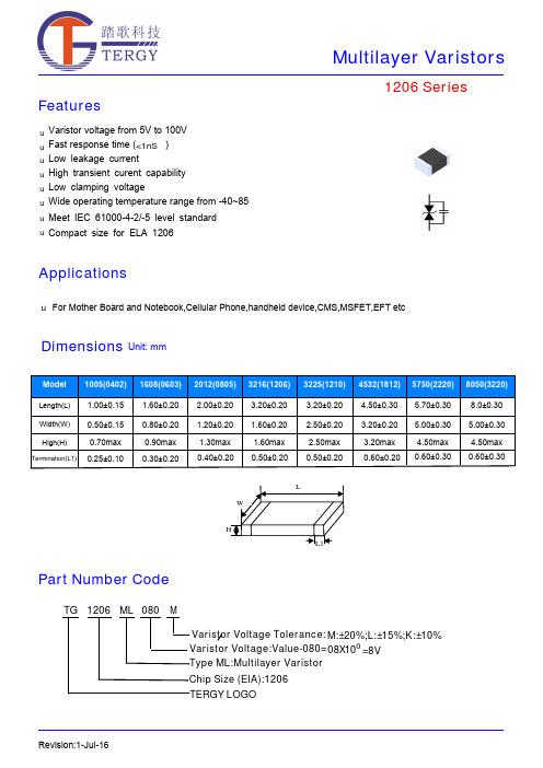
贴片压敏电阻TG1206型号参数规格书
FeaturesApplicationsRevision:18-Jul-161206 SeriesVaristor voltage from 5V to 100V Fast response time ( )Low leakage current High transient curent capability Low clamping voltageWide operating temperature range from -40~85Meet IEC 61000-4-2/-5 level standarduuu uu u u uFor Mother Board and Notebook,Cellular Phone,handheld device,CMO S ,MO S FET,EFT etcDimensionsUnit: mm<1nS℃Compact size for ELA 1206uPart Number CodeTG 1206TERGY LOGO___________ML 080MChip Size (EIA):1206Type ML:Multilayer VaristorVaristor Voltage:Value-080=08X100=8V Varistor Voltage Tolerance:M:±20%;L:±15%;K:±10%Electriacl CharacteristicsRevision:18-Jul-16Surge Current Standard Waveform 1206 SeriesIEC61000-4-5 StandardsT1T2SEVERITY LEVELT1 T2 1 8 uS 20 uS 210 uS1000 uS8/20µs waveform currentOperating Temperature -40 ~ +85ºC Storage Temperature -40 ~ +125ºC Response Time <1 nsSolderability245±5ºC, 3±1sec Solder leach resistance 260±5ºC, 10±1sec Storage Temperature 5 ~ 40ºC Relative Humidity To 65% Taping Package Storage ConditionStorage Time12 Months maxGeneral Technical Data1206 SeriesRevision:18-Jul-16Environmental Reliability TestingCharacteristicTest method and descriptionHigh Temperature Storage The specimen shall be subjected to 125℃ for 1000 hours in a thermostatic bath withoutload and then stored at room temperature and humidity for 1 to 2 hours. The change ofvaristor voltage shall be within 10%.Step Temperature Period 1 -40±3℃30min ±3 2 Room Temperature 1~2hours3 125±2℃30min ±3Temperature CycleThe temperature cycle of specified temperature shall be repeated five times and then stored atroom temperature and humidity for one two hours. The change of varistor voltage shall be within 10%and mechanical damage shall be examined.4Room Temperature 1~2hoursHigh Temperature LoadAfter being continuously applied the maximum allowable voltage at 85℃ for 1000hours, the specimen shall be stored at room temperature and humidity for one or hours, the change of varistor voltage shall be within 10%.Damp Heat Load/Humidity LoadThe specimen should be subjected to 40℃,90 to 95%RH environment, and the maximum allowable voltage applied for 1000 hours, then stored at room temperature and humidity for one or two hours. The change of varistor voltage shall be within 10%.Low Temperature Storage The specimen should be subjected to -40℃, without load for 1000 hours and thenstored at room temperature for one two hours. The change of varistor voltage shall bewithin 10%.Recommended Soldering ConditionsNote that this product will be easily damaged by rapid heating, rapid cooling or local heating.Do not give heat shock over 100°C in the process of soldering. We recommend to take preheating and gradual coolingSoldering gun procedureNote the follows, in case of using solder gun for replacement. 1) The tip temperature must be less than 280 for the period within 3 seconds by using soldering gun under 30W2) The soldering gun tip shall not touch this product directly.Soldering volumeNote that excess of soldering volume will easily get crack the body of this product.Revision:18-Jul-161206 Series◆Carrier tape transparent cover tape should be heat-sealed to carry the products,and the reel should be used to reel the carrier tape.◆The adhesion of the heat-sealed cover tape shall be 40﹢20/﹣15grams.◆Both the head and the end portion of taping shall be empty for reel package and SMT auto-pickup machine.And a normal paper tape shall be connected in the head of taping for the operator handle.type A 0±0.10B 0±0.10K 0±0.10T ±0.05T 2±0.05D 0+0.10D 1±0.05P 1±0.10P 2±0.05P 0±0.05W ±0.20 E ±0.10 F ±0.050402 1.08 1.88 1.04 0.22 0.87 1.50 1.00 4.00 2.00 4.00 8.00 1.75 3.50 0603 1.08 1.88 1.04 0.22 1.17 1.50 1.00 4.00 2.00 4.00 8.00 1.75 3.50 0805 1.42 2.30 1.04 0.22 1.26 1.50 1.00 4.00 2.00 4.00 8.00 1.75 3.50 1206 1.88 3.50 1.27 0.20 1.49 1.50 1.00 4.00 2.00 4.00 8.00 1.75 3.50 1210 2.18 3.46 1.45 0.22 1.77 1.50 1.00 4.00 2.00 4.00 8.00 1.75 3.50 1812 3.66 4.95 1.74 0.25 1.99 1.50 1.50 8.00 2.00 4.00 12.00 1.75 5.50 2220 5.10 5.97 2.80 0.25 3.05 1.50 1.50 8.00 2.00 4.00 12.00 1.75 5.50 32205.50 8.50 2.80 0.30 3.50 1.50 1.50 8.00 2.00 4.00 16.00 1.757.50Packaging Dementions Unit:MillimetersReel DimensionsUnit:MillimetersType A B C D E W W 10402~1210178±160±0.513±0.221±0.22±0.59±0.5 1.5±0.151812~3220178±160±0.513.5±0.221±0.22±0.513.6±0.51.5±0.15Type 04020603080512061210181222203220Quantity100004000400030003000100010001000Packing Quantity。
1206贴片发光管参数
1206贴片发光管参数(原创实用版)目录1.贴片发光二极管的概述2.贴片发光二极管的参数3.贴片发光二极管的应用领域正文一、贴片发光二极管的概述贴片发光二极管,又称 LED 贴片灯珠,是一种采用半导体材料制作而成的发光器件。
它具有低功耗、高亮度、长寿命、环保等特点,广泛应用于各类照明、显示、装饰等领域。
二、贴片发光二极管的参数1.尺寸:贴片发光二极管的尺寸包括长、宽、高三个方向,通常以毫米为单位表示。
常见的尺寸有 3mm×3mm、5mm×5mm 等。
2.颜色:贴片发光二极管的颜色由其发出的光谱决定,常见的颜色有红、橙、黄、绿、蓝等。
3.亮度:贴片发光二极管的亮度是指其发出的光线的强度,单位为烛光(cd)。
亮度越高,光线越亮。
4.视角:贴片发光二极管的视角是指观察者能看到的发光二极管发出的光束的角度范围。
视角越大,光线覆盖的范围越广。
5.工作电压:贴片发光二极管的工作电压是指其正常工作所需的电压,单位为伏特(V)。
一般来说,工作电压越低,越节能。
6.工作电流:贴片发光二极管的工作电流是指其正常工作时通过的电流,单位为安培(A)。
一般来说,工作电流越小,越节能。
7.寿命:贴片发光二极管的寿命是指其正常工作的时间,通常以小时为单位表示。
寿命越长,使用寿命越久。
三、贴片发光二极管的应用领域贴片发光二极管广泛应用于各类照明、显示、装饰等领域,例如:1.照明:包括室内照明、室外照明、交通信号灯等。
2.显示:包括显示屏、广告牌、指示灯等。
3.装饰:包括圣诞树装饰、节日彩灯、室内装饰等。
以上就是关于贴片发光二极管参数的相关信息。
1206红光贴片灯珠规格书

1206红光贴片灯珠规格书1206 red SMD Specifications描述Description1206灯珠最大的优点在于性能稳定,性价比高.市面上用1206灯珠主要用于指示, LCD背光1206 lamp beads the biggest advantage is the stable performance, high cost performance. The market uses 1206 lamp beads mainly used for instructions, LCD backlight.特点Features产品具有亮度高,寿命长的优点,6000小时0光衰The product has the advantages of high brightness, long life, 6000 hours 0 light fa客户名称:CUSTOMER NAME: 经办者: 职称:DIRECTOR: TITLE: 客户料号:CUSTOMER PART NO.: 品名: 版本:PART NUMBER: YT1206ROS1-6200 REVISION: 2.0 发件日期: 回文日期: ISSUE DATE: 2014-11-4 RETURN DATE: / /一、谨致执事者:兹提供敝公司产品之有关详细规格及图面数据,敬请给予办理测试认定手续。
同时敬请送返一份附有贵公司签认之测试认定后之样品认定书。
We are please in sending you herewith our specification and drawings for your approval. Please return to us one copy “For Approval” with your approved signatures. 二、附件:ACCESSORY :□样品 □出货检验记录表 □封装尺寸图 □电气特性曲线□内部线路图 □焊性建议 □PAD 建议 □包装方式 三、客户意见栏 C USTOMER’S PROPOSAL□ AGREE 同意 (请于认可栏中签名) □ DISAGREE 不同意REASON 原因: 客户认可签章:CUSTOMER SIGNATURE:Features_3.2mmX1.6mm SMT LED, 0.90mm THICKNESS. _LOW POWER CONSUMPTION.DescriptionThe Hyper Red source color devices are made_WIDE VIEWING ANGLE._IDEAL FOR BACKLIGHT AND INDICATOR._VARIOUS COLORS AND LENS TYPES AVAILABLE. _PACKAGE: 3000PCS / REEL._RoHS COMPLIANT.Package DimensionsNotes:1. All dimensions are in millimeters (inches).2. Tolerance is ±0.1(0.004") unless otherwise noted.3.Specifications are subject to change without notice. Selection GuidePart No. Dice Lens TypeIv (mcd)@ 20mAViewingAngle Min. Typ. 2 θ 1/2YT1206ROS1-6200RED WATER CLEAR 70 150 120Note:1. θ1/2 is the angle from optical centerline where the luminous intensity is 1/2 the optical centerline value.Electrical / Optical Characteristics at T A=25°CSymbol Parameter Device Typ. Max. Units Test Conditionsλpeak Peak Wavelength RED617 625 nm IF=20mAλD Dominant Wavelength RED nm IF=20mA∆λ1/2 Spectral Line Half-width RED25 nm IF=20mAC Capacitance RED105 pF VF=0V;f=1MHzVF Forward Voltage RED 1.9 2.2 V IF=20mAIR Reverse Curren RED 2 uA VR = 7VRemarks:If special sorting is required (e.g. binning based on forward voltage, luminous intensity, or wavelength), the typicalaccuracy of the sorting process is as follows:1. Wavelength: +/-1nm2. Luminous Intensity: +/-15%3. Forward Voltage: +/-0.1VNote: Accuracy may depend on the sorting parametersAbsolute Maximum Ratings at T A=25°CParameter RED UnitsPower dissipation 75 mWDC Forward Current 30 mAPeak Forward Current [1] 80 mAReverse Voltage 5 VOperating/Storage Temperature -40°C To +85°CNote:1. 1/10 Duty Cycle, 0.1ms Pulse Width.E6C1206URAC1UDA可靠性RELIABILITY测试项目及结果Test Items and Results序号试验项目参考标准试验条件持续时间取样数接收水准(不合格数量/抽样总数)1 温度循环JEITAED-4701-40℃~25℃~100℃~循环100 回合50 0/5025℃30 分钟5 分钟30 分钟 5 分钟2 冷热冲击MIL-STD-202G-40℃~100℃循环500 回合50 0/50 15 分钟15 分钟3 高温储存JEITA ED-4701200 201 T a=100℃1000 小时50 0/504 低温储存JEITA ED-4701200 201T a=-40℃1000 小时50 0/505 常温寿命T a=25±5℃1000 小时500/50 试验I F=20mA6 高温高湿T a=60℃RH=85%1000 小时500/50 寿命试验I F=20mA7可焊性JEITA ED-4701 T sol=235℃±5℃,5 秒焊接一次,5 秒10 0/10 (回流焊)300 303 使用助焊剂8耐焊性JEITA ED-4701 T sol=260℃,10 秒焊接二次,每次10 秒10 0/10 (回流焊)300 301预处理:35℃95%RH96小时备准以上试验项目如与客户试验要求存在差异的或者特殊客户特殊要求的可根据实际情况按照客户的要求进行试作,客户未要求的按我司试验标准试作.不同产品使用不同电流进行测试5.注意事项Cautions(1) 焊接条件Soldering Conditions本产品最多只可回焊两次,且在首次回焊后须冷却至室温之后方可进行第二次回焊.Number of reflow process shall be less than 2 times and cooling process to normal temperature is required between first and Second soldering process.推荐焊接条件(Recommended soldering conditions)有铅回焊(Lead Solder)无铅回焊(Lead-Free Solder)Recommended Soldering Pattern(Units : mm)(2)静电Static Electricity触摸LED 时,推荐使用防静电手腕带或防静电手套.It is recommended that a wrist band or an anti-electrostatic glove be used when handling the LEDs.所有装置、设备、机器均应接地.All devices, equipment and machinery must be properly grounded.静电损坏的LED 会显示出异常特征:正向电压变低或在低电流时死灯.标准: IF=0.5mA 时, VF > 2.0V Damaged LEDs will show some unusual characteristics such as the forward voltage becomes lower, or the LEDs do not light at the low current. Criteria : (VF > 2.0V at IF=0.5mA)(3)防潮包装Moisture Proof Package使用防潮包装It is recommended that moisture proof package be used .(4)使用注意事项Cautions:4.1.在开包装之前,请先检查包装袋有无漏气,如果有漏气现象,请退回我司重新烘烤除湿包装后再使用。
- 1、下载文档前请自行甄别文档内容的完整性,平台不提供额外的编辑、内容补充、找答案等附加服务。
- 2、"仅部分预览"的文档,不可在线预览部分如存在完整性等问题,可反馈申请退款(可完整预览的文档不适用该条件!)。
- 3、如文档侵犯您的权益,请联系客服反馈,我们会尽快为您处理(人工客服工作时间:9:00-18:30)。
20
0/1
20
0/1
① 80 ℃② 100 ℃③ 120 ℃④ 160 ℃⑤
7 IR-Reflow Pb-Free Process 170℃⑥235℃⑦270℃⑧255℃,
20
0/1
60cm/min,2 times
(2)Criteria of judging the damage
-40±5℃→25±5℃→100±5℃→25±5℃
1
Temperature Cycle
20
0/1
(30min,5min,30min,5min) 100 Cycles
2
High Temperature Storage
Ta:100±5℃ Test time=1000HRS(-24HRS,+72HRS)
3
Symbol
Test Min Typ. Max. Unit
Condition
Luminous Intensity
Red
70
150
IV
Green 320 600
-mcd IF =20mA
--
Forward Voltage
Red 1.8
--
2.4
VF
V IF =20mA
Green 2.8
--
3.4
Reverse Current
李忠
Customer Confirmation 客户确认
采购部Pur Dept By 品质部QA Dept By 工程部Eng Dept By
深圳市鑫光硕科技有限公司
SHEN ZHEN XIN GUANG SHUO TECHNOLOGY CO.,LTD
公司地址:广东省深圳市宝安区沙井万丰村前路31号8楼
承认书
SPECIFICATION FOR APPROVAL
客户 Customer:
客户品号 Customer P/N:
鑫光硕品号 Xgs Model:
规格 Specification :
XGS-PB3216UEUG-04 SMD 1206红翠绿双色 20MA
制作 Prepared By:
审核 Checked By:
◆ Soldering Pad Dimensions:
◆ Soldering Conditions (Maximum allowable soldering conditions)
Reflow soldering profile
<Pb-free solder>
Temperature
3℃/sec.
210℃ Pre-heating 120~160℃
Water Clear --
Electrodes: Au Plating Encapsulating Resin: Epoxy Resin Package: BT Resin
Page 1 of 8
Unit:mm Tolerance:±0.1
Absolute Maximum Rating (Ta=25℃)
Topr
-40℃~85℃
℃
Storage Temperature Range
Tstg
-40℃~100℃
℃
IFP condition: pulse width ≤1ms ,duty cycle ≤1/10
Electrical Optical Characteristics(Ta=25℃)
Parameter
◆ Applications:
Automotive and Telecommunication Flat backlight for LCD ,switch and symbol in telephone and fax General use for indicators
◆ Package Dimensions:
Parameter
Value
Symbol
Unit
R
G
Power Dissipation
PM
60
80
Mw
Pulse Forward Current
IFP
125
mA
DC Forward Current
IF
20
mA
Reverse Voltage
VR
5
V
Operating Temperature Range
Customer confirm Approved by Checked by
Issued by
Part No.
XGS-PB3216UEUG-04
Emitted Color
Red
Blue
Len'sColor
Chip Material AlGaInP/GaAs InGaN/GaN
--
◆ Features:
Before opening the package: The LEDs should be kept at 5~30°C and 60%RH or less. The LEDs should be used within a year. After opening the package: The LED must be used within 24 hours, else should be kept at 5~30℃ and 30% RH or less. The LEDs should be used within 7days after opening the package. If unused LEDs remain, they should be stored in moisture proof packages, recommended to return the LEDs to the original moisture proof bag and to reseal the moisture proof bag again.
一厂地址:广东省深圳市龙岗区嶂背创业二路18-1号
二厂地址:广东省东莞市石排镇庙边王村沙迳工业区
Tel: 13798585378
QQ:2373888283
Website :
E-mail:xz@
· Customer:
Technical Data Sheet
Page 3 of 8
◆ Package Tape Specifications: (4000 pcs/Reel)
Feeding, Direction
Dimensions of Reel ( Unit: mm)
Dimensions of Tape (Unit:mm)
Arrangement of Tape(Unit:mm)
Page 4 of 8
◆ Typical Electro-Optical Characteristics Curves:
Page 5 of 8
Reliability
(1) Test Items and Conditions
NO
Test Item
Test Conditions
Ac/ Sample
Re
Compatible with automatic placement equipment Compatible with reflow solder process Low power consumption and wide viewing angle This product doesn’t contain restriction Substance, comply ROHS standard.
3℃/sec.
260℃ Max. 10sec.Max.
60~120sec.
-4℃/sec.
120se.c.Max.
Time
• Reflow soldering should not be done more than two times. • Do not stress its resin while soldering. • After soldering,do not warp the circuit board.
Red
--
--
10
IR
uA VR=5V
Green --
--
10
Red 615 625 Dominant Wavelength λd
Green 515 530
-nm IF=20mA
--
Viewing Angle
Red
--
140
--
2θ1/2
Deg. IF =20mA
Green --
140
--
Notes: 1.Tolerance of Luminous Intensity ±10%
If the LEDs have exceeded the storage time, baking treatment should be performed more than 24hours at 60±5°C. 3、Soldering Iron Each terminal is to the tip of soldering iron temperature less than 300℃ for 3 seconds within once in less than the soldering iron capacity 25 W.Leave two seconds and more internals, and do soldering of each terminal. Be careful because the damage of the product is often started at the time of the hand solder. 4、Repairing
