CLW电容料位开关说明书
Capanivo 料位开关 电容式 CN 8000 技术信息 操作手册说明书

CN 8000 agi1509171page 内容目录页码安全须知/技术支持 2----------------------------------------------------------------------------------------------------- 简介 应用 / 功能 / 特点 3-----------------------------------------------------------------------------------------------------技术参数电气参数 9 机械参数 10 操作条件 11-----------------------------------------------------------------------------------------------------安装 16-----------------------------------------------------------------------------------------------------电气安装 20---------------------------------------------------------------------------------------------------------------------------------------------------------------------------------------------------------------------------------------------------------------------------------------------------------------危险区域应用须知 32-----------------------------------------------------------------------------------------------------Profibus 总线通讯系统实施尺寸认证操作 - 电子模块:标准操作 - 电子模块:数显探头改造截短电缆(缆式)参数若有变化,恕不另行通知。
Pointek CLS200 点式物位计 - 电容开关 标准型 说明书
Pointek CLS200(标准型)是一个反相频移式电容物位开关,它可选杆式/缆式和可选配置输出。
它适用于检测液体,固体,泥浆,泡沫和界面。
• 一体式结构保护信号电路不受冲击,振动,湿度和/或冷凝水的影响。
• 耐化学腐蚀。
• 物位检测不受罐壁或管道地面参考的影响。
• 基于高频振荡,对物料堆积不敏感。
• 三个LED指示灯用于指示传感器状态,输出状态和电源。
• SIL/IEC61508可用于安全级别高的场合,防止溢出(SIL-2) Pointek CLS200标准型有三个带有基本继电器和固态开关报警的LED指示灯。
电源是电隔离的,适用的电压范围很广(12至250 V AC/DC)。
当与热隔离器一起使用时,由于探头部分的材料是不锈钢和PPS (PVDF可选)的,则在工作过程中探头接液部分的额定温度最高可达到125 °C。
通过检测振荡频率的变化,开关可响应任何介电常数大于等于1.5的介质,同时它可设置为接触探头前检测或接触探头时检测。
CLS200的工作独立于罐壁或管道,在不导电容器(如:混凝土或塑料)中进行物位探测时,它不需要外部参比电极。
• 关键的应用:液体,泥浆,粉末,颗粒剂,带压应用,危险区域。
Pointek CLS 200安装1521531) 当工作区域被划分为危险区域时,应根据相关证书遵守各项限制。
也可以参考压力/温度曲线5/23页。
2) 如果过程连接温度超过+85 °C ,则需使用热隔离。
3) 过程密封的额定压力取决于温度。
参考压力/温度曲线5/23。
1541) PFA 涂层 (7ML5634和7ML5644)有120微米厚。
2)如果过程连接温度超过+85 °C,则使用热隔离器。
155156157158159160Pointek CLS200数字型有一个独立的液晶显示屏,和PROFIBUSPA通讯(版本3.0,Class B)用于连接到网络中。
电源是电隔离的,适用的电压范围很广(12至250 V AC/DC)。
静电容料位开关

二、感度调整:
用户依控制物料所需灵敏度调整感度调整钮“SENSITIVITY”指示箭头的位置,调整至物料接触到感测棒时LED灯亮,而当物料尚未接触到感测棒时LED灯灭为止。(注:灵敏度调节有问题时请通知本公司,本公司将有专人解答。)
配线方法
1.标准型及DC24V型/粉尘防爆及隔爆型(SA-27系列)
①打开接线盒,将电缆线从入线口穿进并锁紧入线口电缆固定螺丝,根据铭牌及电路板端子台上的标示将电源线、接点线接入对应的端子上。(电缆线建议使用16AWG或18AWG耐温可达80℃之电缆线)
②配线完成后将接线盒内部的杂物清除,再将接线盒盖锁紧。
2.本安防爆型(SA-37系列)
①打开接线盒,将电缆线从入线口穿进并锁紧入线口电缆固定螺丝,按电路板标示(0V、24V、O/P)将线接在电路板端子上。再将线穿墙按顺序接入SA-75U端子上,其对应顺序为0V—-、24V—+24Vdc、O/P—IN。(电缆线建议使用16AWG或18AWG耐温可达80℃之电缆线)
调整Delay可变电阻至
适当延长时间
②继电器损坏
更换继电器
若非以上问题,可来电本公司由技术人员解答;未经同意,请勿自行拆解维修。
日常维护
1.定期清除感测头上的附着物,周期可根据产品使用介质不同来确定,若开关用于液体或粘性较强的固体,则周期应短些;若开关用于粘性弱的固体,则周期可长些。
2.若产品为耐酸碱型,须定期检查本产品零部件是否被腐蚀。
铝电解电容器的使用说明书分析
铝电解电容器的使用说明书铝电解电容器如在非规定条件下使用的话,会导致爆炸失火等重大故障,请先确认下述注意事项后使用。
工作温度与纹波电流1.检查电容器的工作和安装环境,确保在产品目录或规格书的规定条件下。
2.工作温度、纹波电流应在规定的范围内,电容器如通过太大电流则引起异常发热、短路、失火等致命不良。
3.电容器本身为发热元件,会使机器内温度上升,这点请注意,确认机器正常状态下,电容器周围的温度。
4.允许通过的纹波电流应随环境温度(电容器周围的温度)上升而降低,允许通过纹波电流应考虑最高环境温度。
5.电气参数随着频率的变化而变化。
选好电容器必须考虑频率的变化。
特别需要注意无论在低频和高频使用时,电容器的自身发热会使等效串联电阻和自感变化,缩短了使用寿命。
施加电压和其它工作条件1.电容器有极性,施加反向电压或交流电压后,会导致压力阀释放或短路失火等致命不良。
交流电压情况下使用特殊的交流电容器。
2.在极性转换电路中请使用双极性电容,但这种情况不使用于交流电路。
3.不要施加过电压,即直流电压上叠加交流成分时,峰值不要超过额定电压,否则会引起短路失火等致命重大不良。
4.浪涌电压有严格的条件限制,在此条件下不能保证长时间工作。
工作电压即使短时间内也不要超过额定电压,请慎重选择电容器。
5.多只电容器并联时,应考虑导线电阻,使每个电容器上的导线电阻值相等。
6.多只电容器串联时使用同一规格的电容,请并联均压电阻,设计时要考虑这时加在电容上的电压完全一样,确保施加在电容器上的电压不超过额定电压。
7.使用电容器时需要考虑设备的使用寿命。
超过使用寿命时,继续使用则电容器存在压力阀释放或短路隐患,定期点检时按需替换。
8.不能用于重复急剧充放电电路。
熔接机器等充放电时,电容器请特别设计。
一些旋转设备的控制电路,如伺服驱动和充放电电路中选用合适的电容器,请与海立联系。
9.即使非快速充放电,但电压变化大则会导致寿命特性恶化,要实际上机认真确认或与海立联系。
音叉式料位开关说明书
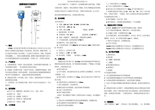
射频导纳开关说明书(L2000)一、概述L-2000系列射频导纳物位控制器是我公司科研人员在总结国内外大量物位仪表的基础上开发成功的,其技术性、测量可靠性,已在大量应用中得到了充分体现。
广泛适用于各类料仓、容器、管道的料空料满测量,上、下限自动报警或检测。
报警时可输出继电器开关信号,经中间继电器或直接与启动设备连锁,可实现上料、下料的自动控制。
二、产品特点1. 安装调试简易:全密封一体化安装结构,全部采用数字集成电路,无任何机械可动部件。
一经安装校零无需多次调试。
2. 低温漂:采用数字电器,与现有产品比较,大幅降低环境温度、湿度对仪表进行的影响,换季无需调零。
先进的电路设计能避免物料粘附在探头所产生的虚假信号,又能抗各种波动所造成的影响。
3. 现场适应性强:可在高温、高压、大粉尘、高粘度的场合中对固体及液体物料进行检测。
4.一次性校零:由于采用数字电路,使用户可以在空仓的状态下一次完成校零。
三、适用领域a)电力工业:输煤系统、除灰系统(灰斗、仓泵、灰库)b)建筑工业:水泥厂c)食品工业:面粉罐、包装料斗d)制药工业:原料贮仓、配料混合罐e)造纸工业:木屑仓、液罐四、工作原理由电子线路产生一个高频信号,送至测量电极与保护电极,当物料位置改变时,就把这一变化反馈给电子线路,而电子线路通过容抗和阻抗的综合变化信号与基准信号作比较,当两信号相差达到一定大小时,就改变继电器的输出状态,从而指示物位变化。
五、技术参数a)控制部分1. 电源:220V AC±10%,50/60HZ;24V DC±10%;2. 触点容量: 250V AC 5A;3. 功耗:最大2.5W;灵敏度:≤0.3PF;4. 输出继电器:单刀双掷;5. 环境温度:-40~65℃;温度影响:0.3PF/30℃;6. 校准:按键校零灵敏度设置:设置范围为1-9档;7. 开关延时设置:延时值范围为0-59秒;8.报警形式:可选上限或下限;9:外壳防护标准:符合NEMAI-5.4X和12&13(IP65)的防护标准。
CMCL使用手册

软起动器使用安全注意事项警告!主回路电源得电后即存在危险电压。
警告!电机停止后,主回路上依然存在危险电压,须在软起动器断电后,再打开前面板。
警告!CMC—L软起动器停止后,继电器端子上(6、7、8、9)依然存在危险电压。
警告!不允许软起动器输出端(2L1、4L2、6L3)接补偿电容器或压敏电阻。
警告!电机综合保护器应接于软起动器输入端(1L1、3L2、5L3),不允许接于输出端。
警告!软起动器与变频器混用时,二者输出端要彼此隔离。
警告!不要试图修理损坏的器件,请与供货商联系。
警告!散热器的温度可能较高(在线运行方式下)。
警告!严禁在软起动输出端反送电。
目录1.产品简介 (1)2.产品型号及收货检查 (2)3.安装 (3)4.接线 (4)& 主回路接线 (4)& 控制回路接线 (4)& 控制端子说明 (5)5.显示 (7)& 功能特点 (7)& 键盘说明 (8)& 显示状态说明 (8)6.设定及操作 (9)& 编程操作 (9)& 参数设定及说明 (9)7.维护 (10)8.故障分析 (11)9.技术参数 (13)& 一般参数 (13)& 基本接线图 (14)10.不同应用的基本设置 (15)1.产品简介及特点CMC-L系列电机软起动器是一种将电力电子技术,微处理器和自动控制相结合的新型电机起动装置。
它能无阶跃地平稳起动/停止电机,避免因采用直接起动、星/三角起动、自耦减压起动等传统的起动方式起动电机而引起的机械与电气冲击等问题,并能有效地降低起动电流及配电容量,避免增容投资。
CMC-L系列软起动器特点如下:①多起动方式:限流起动、斜坡起动、斜坡限流起动,最大程度满足现场需求,实现最佳起动效果。
②高可靠性:有高性能微处理器对控制系统中的信号进行数字化处理,避免了以往模拟线路的过多调整,从而获得极佳的准确性和执行速度。
③强大的抗干扰性:控制单元中的信号均采用光电隔离方式,并设置了不同的抗噪级别,避免了主电网上干扰引起的软起动器误动作。
电容料位开关

电容料位开关
电容料位开关一般是指采用技术超声波测量变送器在介质中的容积,从而实现介质位
置的监测控制。
它可以在管道、槽、容器内精确检测介质高度,并可以采用无接触原理测
量介质,动态方式计算介质高度,并根据结果自动控制各种介质位置。
电容料位开关又称
容位开关,是目前用于介质高度检测的被广泛应用的一种传感器,它采用容定位原理,利
用改变介质的内聚力,通过低频发出的声波进行探测介质的高度,并把检测的结果反馈给
控制系统,实现介质高度的精确控制。
电容料位开关具有良好的稳定性,测量准确率高,非接触式检测,无耗材,易于安装,使用及维护,适用于恶劣的工况,特别是腐蚀性介质和有悬浮颗粒的工况等,电容料位开
关的优点使其成为用于检测介质位置的理想选择。
电容料位开关的结构组成比较简单,主要由安装结构、发射器、接收器和控制器等组成,安装结构或容器内增设发射器和接收器,在发射器收送约500kHz-1MHz的信号,介质
里有物质时会发出回波,被接收器收集,再传到控制器,根据设置信号强度大小和反馈信
号大小比较,位置上的差距得到,从而控制输出开关控制信号。
电容料位开关的工作原理中,各个元件的性能和响应速度都有一定的影响,因此在选
择电容料位开关时,一定要确定介质特性,如液体密度,液体温度,介质表面张力,介质
对声波的反射率,介质中有其他粒子、矿物等,有些物质会影响电容料位开关的传播和检测,因此,在选择电容料位开关时,必须考虑介质特性,以确保其准确性和可靠性。
Pointek CLS300 电容触摸开关(标准版)应用示例说明书
Pointek CLS300 Capacitance Switch (Standard Version)Application examples Introduction1 Overview2 Planning/configuring3Siemens AG Digital Industries Document order number: AG080910_CLS300Ⓟ 10/2020 Subject to changeCopyright © Siemens AG 2020.All rights reservedLegal informationWarning notice systemThis manual contains notices you have to observe in order to ensure your personal safety, as well as to preventdamage to property. The notices referring to your personal safety are highlighted in the manual by a safety alertsymbol, notices referring only to property damage have no safety alert symbol. These notices shown below aregraded according to the degree of danger.DANGERindicates that death or severe personal injury will result if proper precautions are not taken.WARNINGindicates that death or severe personal injury may result if proper precautions are not taken.CAUTIONindicates that minor personal injury can result if proper precautions are not taken.NOTICEindicates that property damage can result if proper precautions are not taken.If more than one degree of danger is present, the warning notice representing the highest degree of danger willbe used. A notice warning of injury to persons with a safety alert symbol may also include a warning relating toproperty damage.Qualified PersonnelThe product/system described in this documentation may be operated only by personnel qualified for the specifictask in accordance with the relevant documentation, in particular its warning notices and safety instructions.Qualified personnel are those who, based on their training and experience, are capable of identifying risks andavoiding potential hazards when working with these products/systems.Proper use of Siemens productsNote the following:WARNINGSiemens products may only be used for the applications described in the catalog and in the relevant technicaldocumentation. If products and components from other manufacturers are used, these must be recommendedor approved by Siemens. Proper transport, storage, installation, assembly, commissioning, operation andmaintenance are required to ensure that the products operate safely and without any problems. The permissibleambient conditions must be complied with. The information in the relevant documentation must be observed. TrademarksAll names identified by ® are registered trademarks of Siemens AG. The remaining trademarks in this publicationmay be trademarks whose use by third parties for their own purposes could violate the rights of the owner. Disclaimer of LiabilityWe have reviewed the contents of this publication to ensure consistency with the hardware and softwaredescribed. Since variance cannot be precluded entirely, we cannot guarantee full consistency. However, theinformation in this publication is reviewed regularly and any necessary corrections are included in subsequenteditions.Table of contents1 Introduction (4)1.1 Objective (4)1.2 Equipment (4)1.3 Disclaimer (4)2 Overview (5)3 Planning/configuring (6)3.1 Adjusting the Setpoint (6)3.2 Pointek CLS300 Applications (6)3.3 Calibration for general applications (Failsafe low, no delay) (7)3.4 Calibration for demanding applications (Failsafe low, no delay) (7)3.5 Calibration for interface detection (Failsafe low, no delay) (7)3.6 Alarm Delay Function (8)3.7 Testing the Alarm Delay (8)3.8 Operation (8)1.1ObjectiveThe objective of this application guide is to help the user become familiar with the stepsrequired to set up and calibrate the Pointek CLS300 (Standard Version). This application guideapplies to any models manufactured after January 26, 2011.1.2Equipment1.3DisclaimerNoteWhile every effort is made to verify the following information, no warranty of accuracy orusability is expressed or implied.This application guide is an addition to the operating instructions. Please review CLS300 (Standard Version) operating instructions to ensure that the device is properly mounted. This application guide provides a basic procedure for setting the switch point for correct operation of the CLS300 (Standard Version) in either covered or uncovered states. Please note that the guide applies only to hardware manufactured after January 26, 2011 as indicated by a serial number of PBD/B127xxxx or higher. (For example, PBD/C9xxxxxx or PBD/B128xxxx.)Included in the guide are the appropriate start up procedures to quickly and effectively set up the Pointek CLS300 (Standard Version) capacitance switch for general applications, demanding applications and interface detection. It also contains instructions for adjusting the setpoint and alarm delay.For more detailed information, please consult the operating manual (A5E47827796).3.1Adjusting the SetpointBefore adjusting the setpoint or alarm delay the cover must be removed.Prior to removing the cover, please ensure that power is removed, and that the applicationand installation allow for removal of the cover. (This may not be permitted in someHazardous Areas.)Once the cover has been removed, apply power to the unit. The green power LED (L3) willglow indicating that the unit is powered and operational. If L3 is not on, please consult theSpecifications and Troubleshooting sections of the operating instructions.3.2Pointek CLS300 ApplicationsPointek CLS300 can be set up for three different applications which are described in the tablebelow. Use the calibration procedure for the application that most closely describes youroperation.Application Material Setup ConditionsGeneral •dry solids•low viscosity liquids sensor uncovered;min. 100 mm (4") free space all aroundDemanding •hygroscopic / wet solids•high viscosity and high conductivityliquids sensor immersed then uncovered; but retaining max. possible material buildupInterface detection •liquid A / liquid B•foam / liquid immerse sensor in whichever material has lowest dielectric constant3.3 Calibration for general applications (Failsafe low, no delay)3.3Calibration for general applications (Failsafe low, no delay)1.Ensure that the green power LED (L3) is on.2.Set DIP switches S1 to S5 to OFF (rocker down as shown in the diagram above).3.Turn the delay potentiometer (P1) fully counter-clockwise.4.Adjust the material level of the process so that the probe is uncovered with a minimum of100 mm (4”) free space all around.5.If the yellow sensor status LED (L1) is on, proceed to step6. If L1 is off, turn the trip pointpotentiometer (P2) counter-clockwise until it just turns on. If the yellow LED does not turnon set DIP switch S5 to ON and repeat step 5.6.Slowly turn the trip point potentiometer (P2) clockwise until the yellow sensor status LED(L1) just turns off.3.4Calibration for demanding applications (Failsafe low, no delay)1.Ensure that the green power LED (L3) is on.2.Set DIP switches S1 to S5 to OFF (rocker down as shown in the diagram above).3.Turn the delay potentiometer (P1) fully counter-clockwise.4.Adjust the material level of the process so that the sensor is immersed.5.Adjust the material level of the process so that the sensor is uncovered, but retains as muchbuildup of material as possible.6.If the yellow sensor status LED (L1) is on, proceed to step7. If L1 is off, turn the trip pointpotentiometer (P2) counter-clockwise until it just turns on. If the yellow LED does not turnon set DIP switch S5 to ON and repeat step 6.7.Slowly turn the trip point potentiometer (P2) clockwise until the yellow sensor status LED(L1) just turns off.3.5Calibration for interface detection (Failsafe low, no delay)1.Ensure that the green power LED (L3) is on.2.Set DIP switches S1 to S5 to OFF (rocker down as shown in the diagram above).3.Turn the delay potentiometer (P1) fully counter-clockwise.4.Adjust the material level of the process so that the sensor is covered by the material with thelowest relative dielectric constant.5.If the yellow sensor status LED (L1) is on, proceed to step6. If L1 is off, turn the trip pointpotentiometer (P2) counter-clockwise until it just turns on. If the yellow LED does not turnon set DIP switch S5 to ON and repeat step 5.6.Slowly turn the trip point potentiometer (P2) clockwise until the yellow sensor status LED(L1) just turns off.3.6 Alarm Delay Function3.6Alarm Delay FunctionIf you want to slow the Pointek CLS300 response, to compensate for turbulence or falsereadings, set a delay interval using the delay potentiometer (P1) and set DIP switches S1and/or S2 to the OFF position to enable the delay for either alarm activation (S1 OFF), alarmde-activation (S2 OFF), or both (S1 and S2 OFF). (Note: This information can usually be foundinside the device cover.)If an immediate alarm output is critical, disable the delay by setting the appropriate switch(either S1 or S2) to ON. The functioning of switches S1 and S2 depends on the alarm setting:3.7Testing the Alarm DelayThis test procedure assumes that you have completed one of the calibration processesdescribed previously.1.Grasp the probe with your hand. The yellow sensor status LED (L1) should turn onimmediately. The red output status LED (L2) should turn on after a delay.2.Turn the delay potentiometer (P1) clockwise about 1/8 of a turn.3.Turn DIP switch S4 to the ON position; this will simulate a change in state of the probe(covered/uncovered).4.L1 (the yellow LED) should turn on immediately, and L2 (the red LED) should turn on after alonger delay than in Step 1.5.Turn DIP switch S4 to the OFF position.6.Continue to adjust the delay potentiometer (P1) until you have the desired delay.3.8OperationAfter completing the setup, replace the lid and secure the lid clip. Pointek CLS300 Standardmodel is now ready to operate.。
德力西 JKL5CV JKL2CV 智能无功功率自动补偿控制器 说明书

JKL5CV/JKL2CV智能无功功率自动补偿控制器使用说明书符合标准:JB/T 9663安装、使用产品前,请仔细阅读使用说明书并妥善保管、备用1概述1.1使用说明本说明书详细地介绍安装、调试、工作参数、菜单操作等内容,用户在使用之前必须仔细阅读此说明书,必须由专业的电工进行安装;安装前要确保产品、使用设备各部分无电,才可以进行操作,杜绝带电操作,以防人体触电。
1.2使用范围适用于低压配电系统电容器补偿装置的自动调节,使功率因数达到用户预定状态,提高电力变压器的利用功率,减少线损,改善供电的电压质量。
2功能特点1.以基波无功功率计算投切电容容量,可避免任何形式的投切震荡,并在有谐波的场合下,能正确显示功率因数。
2. 功率因数测量精度高,显示范围宽。
3. 实时显示基波功率因数。
4. 实时显示电压畸变率及电流畸变率。
5. 具有多种编码输出方式供用户选择。
6.最多可选配12个控制回路的输出。
7.人机界面友好操作方便。
8.各种控制参数全数字可调,使用方便。
9.具有自动运行与手动运行两种工作模式。
10.具有过电压和欠电压保护功能。
11.具有电压谐波超标保护功能。
12.具有断电保护功能数据不丢失。
13.电流信号输入阻抗低≤ 0.01Ω。
14.通讯功能可选。
特殊说明:与光伏发电混用场合,需要将光伏接入点置于该互感器前端,互感器下端只包括负载电流+电容电流,不能包括光伏。
3使用条件1.海拔高度≤2000米(特殊要求协商确定)。
2.周围空气温度 -25℃~+40℃。
3.相对湿度,在40℃时不超过50%;20℃时不超过90%。
4.周围环境无腐蚀性气体,无导电尘埃,无易燃易爆的介质存在。
5.安装地点无剧烈震动4技术数据额定工作电压:AC 380V(JKL5CV)或AC 220V(JKL2CV)额定工作电流:AC 0~5A额定工作频率:45Hz~65Hz显示功率因数:滞后0.001~超前0.001测量无功功率:0~9999kvar测量有功功率:0~9999kW测量视在功率:0~9999kVA欠压保护值:AC 300V或AC 170V输出触点容量:AC220V 5A 阻性,AC380V 3A 阻性灵敏度:50mA整机消耗功率:10VA显示:4位红色数码管外型尺寸:122mm×122mm开孔尺寸:112mm×112mm安装方式:嵌入式安装倒齿附件固定连接方式:接线端子螺丝固定防护等级:外壳IP30,操作面板IP405面板功能介绍5.1指示灯说明1.1~12路电容投入指示灯;2.A/M 手动/自动运行指示灯:常亮时表示自动运行,熄灭时表示手动运行。
液晶显示器CL WA 维修手册

现像:切换到灰阶画面可看到某些阶有彩条并以中心点对称(如图)。 分析:灰阶不良主要为时序IC不良或LVDS接口不良或Source Drive不良引起。 检测:测TP101~TP123对地阻值,均正常,测左右半屏的对地阻值,也均正常,此时 产生疑难问,为什么测试值均正常会产生灰阶不良,再认真观察,补焊CN101,有一引 脚被烙铁焊下,发现此PIN是原先已断的。 维修:更换CN101,画面正常。 原因:CN101不良。
power supply input voltage(5.0V)
CLAA220WA01维修手册 - 6
PCB Board功能分布图
To Gate Driver测试点
VCOM微调电位器,
Source Driver(x8)
VCOM测 试点
正面图
左半屏测 试点位
3.3V稳压管
DC-DC CONTROL
时序控制
ground minus signal of odd clock channel(LVDS) plus signal of odd clock channel(LVDS)
minus signal of odd channel 3(LVDS) plus signal of odd channel 3(LVDS) minus signal of even channel 0(LVDS) plus signal of even channel 0(LVDS)
CLAA220WA01维修手册 - 3
Connector(30Pin)
Gate Driver(x4)
CLAA220WA01 PANEL PCB MODULE
LVDS receiver 2ch Timing controller
微型 料位开关

微型料位开关全文共四篇示例,供读者参考第一篇示例:微型料位开关是一种用于检测和监控物料水平的设备,其小巧轻便的设计使其非常适合安装在狭小空间或者对装载有限的设备上。
这种开关通常由功能性部件和外壳组成,通过不同的工作原理来实现物料水平的检测。
它们被广泛应用于各种工业领域,如食品加工、化工、医药等,起到了非常重要的作用。
微型料位开关的种类繁多,主要可以分为浮球式、振动式、电容式等几类。
浮球式料位开关通过浮球的上升和下降来开关触点,当物料水位达到一定高度时,浮球会浮在物料表面,从而使开关触点闭合;而当物料下降到一定程度时,浮球则会沉下来,开关触点则会断开。
这种操作原理简单易懂,且结构稳定,因此在许多行业得到广泛运用。
振动式料位开关则是通过探头上的振动部件来实现物料水位的检测,当物料达到一定高度时,会阻碍振动部件的振动,触发开关动作;反之,在低水位时则不会有阻碍振动的物料存在,保持开关处于关闭状态。
这种类型的料位开关由于设计简洁、敏感度高、不易受外界干扰,因此被广泛应用于粉体、颗粒物料的检测领域。
电容式料位开关通过物料和电容传感器之间的介电常数差异来实现开关触点的动作。
当物料接触到电容传感器时,会改变电容传感器感应的电容值,从而触发开关的动作。
这种类型的料位开关具有精确的检测能力,可以应用于各种不同介电常数的物料,具有较强的通用性和灵活性。
微型料位开关在工业领域有着广泛的应用,可以用于物料的控制、监测和报警。
在食品加工行业,微型料位开关可以用于监测食品的水平,确保生产过程的顺利进行,同时也可以用于检测食品的残留物料,保障产品质量。
在化工行业,微型料位开关可以用于监测化工原料的储存和消耗情况,及时控制生产过程,确保生产安全。
在医药行业,微型料位开关可以用于监测药品的存储情况,精准控制药品的配料比例,保障产品质量。
虽然微型料位开关在工业领域有着广泛应用,但是在选择和安装时仍需注意一些问题。
需要根据物料的特性来选择适合的料位开关类型,确保其可以正确地检测物料水平。
阻旋料位开关说明书

阻旋料位开关说明书基本参数:电源:220V AC/50HZ 消耗功率:4W接点容量:SPDT 5A/250V AC 叶片转速:1RPM耐电压:AC 1500V×1minute 测量扭矩:1.0 N·m适用比重:0.5g/cm3以上工作温度:-20~80℃/高温型-20~400℃工作原理:阻旋式料位开关之叶片是利用传动轴与离合器相接,在未接触物料时,马达保持正常运转;当叶片接触物料时,马达电源断开并停止运动,机构同时输出一接点信号表示料位已到设定高度。
安装注意事项1.水平安装时,建议将开关以水平向下呈15℃~20℃的夹角安装,以减少物料的冲击。
2.接线盒入口必须朝下,电缆固定螺母必须锁紧。
3.送电时应确认使用电压正确。
4.被控制线路负载必须与开关接点容量相匹配。
5.安装产品附近应避免有架桥破坏器或震动马达。
6.开关安装避免靠近入料口,以减少下料损坏叶片及误动作;若开关必须安装在靠近入料口处,请在开关上方200mm处加装一2mm宽的保护挡板。
7.各产品安装时根据其型号不同,选择水平安装和垂直安装。
8.轴长可调型开关在现场解体安装时,万向接头与传动轴连接时,锁紧螺母必须涂上缺氧胶,然后再用扳手锁紧。
9.现场安装、维护必须遵守“断电源后开盖”的警告语。
10.安装现场不存在对铝合金有腐蚀作用的有毒气体。
11.被测介质的最高温度不应超过产品标签中标明的温度。
12. 产品安装时请勿直接敲击叶片及传动轴。
扭力调整:1.用户可根据被测物的比重大小进行扭力调整。
当被测物比重大时,可将弹簧扭力调至最强的位置,此时叶片的灵敏度较差;被测物比重越小时,可将弹簧调至愈弱,则叶片的灵敏度较好。
2.具体方法:打开接线盒,将扭力弹簧靠近多孔一端拿出,根据需要插入对应的孔中(靠近端子台的孔扭力最弱)。
●注意在使用过程中扭力弹簧的扭力,请勿随意更换,以免造成误动作。
常见故障及排除:NO 故障排除原因分析排除方法1 物料传达时,叶片仍传动叶片尺寸与物料比重不符重新确定叶片尺寸2 叶片变形或传动轴变形弯曲物料冲击力太大作适当防护措施3 叶片不转动1.电源未接好检查线路将线接好2.马达烧坏与本公司联系更换马达日常维护:1.检查传动轴、叶片是否弯曲变形或损坏。
24v阻旋料位开关说明书800字左右
24v阻旋料位开关说明书800字左右24V阻旋料位开关说明书一、产品概述:24V阻旋料位开关是一种用于测量物料液位的装置。
它采用24V电源供电,通过阻旋原理实现对液位的检测和控制。
二、产品特点:1. 采用24V直流电源供电,安全可靠。
2. 阻旋原理,精确测量物料液位。
3. 结构简单,安装方便。
4. 高灵敏度,快速反应。
三、产品结构:1. 主体部分:由外壳、电路板和连接线组成。
2. 阻旋装置:由旋钮和测量装置组成。
四、使用方法:1. 将24V阻旋料位开关连接至电源。
2. 将测量装置浸入待测物料中,确保与液体充分接触。
3. 旋转旋钮,调整测量装置的位置,使其与液位保持一定距离。
4. 当液位达到测量装置位置时,开关自动触发,信号输出。
五、注意事项:1. 在安装和使用过程中,请确保电源线与其他设备保持安全距离,以防电路短路或其他故障。
2. 使用时请遵循操作规程,避免过度旋转或强行改变测量装置的位置。
3. 请勿将开关浸入液体中,以免损坏电路或引发其他安全问题。
4. 使用前请检查设备是否完好,如有损坏,请及时维修或更换。
六、维护与保养:1. 定期检查设备的电源线和连接线是否完好,如有损坏,请及时更换。
2. 定期清洁测量装置和旋钮,以确保灵敏度和准确度。
3. 如发现设备异常或工作不正常,请立即停止使用,并联系专业维修人员进行检修。
七、常见问题及解决方法:1. 问题:开关无法触发。
解决方法:请检查电源线是否连接正常,如有损坏,请更换。
2. 问题:开关触发不准确。
解决方法:请检查测量装置的位置是否正确,适当调整旋钮位置,确保与液位保持一定距离。
以上是24V阻旋料位开关的使用说明书,希望能够对您的使用和维护提供帮助。
如有任何问题,请随时联系我们的客服人员。
感谢您选择使用我们的产品!。
电容物位计使用说明安全操作及保养规程

电容物位计使用说明安全操作及保养规程前言电容物位计,是一种经过精细计算的高精度液位测量仪器。
它可以广泛应用于各种行业,包括化学、石油、食品、制药、医疗等领域,并且在水处理、污水处理、石油加工、烃类液体采样和石油管道和储罐的液位测量方面有重要的应用。
本文将介绍电容物位计的使用说明、安全操作及保养规程。
电容物位计的使用说明1. 确认电容物位计的型号在使用电容物位计之前,需要确认所持有的电容物位计的型号。
因为不同型号的电容物位计有不同的测量精度及精确度范围,因此必须对型号进行确认才能确保测量的准确性。
2. 安装电容物位计在安装电容物位计之前,需要先了解流量计量管道的形状、直径、长度、材料等信息。
将流量计放置在电容物位计的电极中间,电容物位计的电极必须保持彼此对称。
3. 进行测量在进行测量之前,需要先对电容物位计进行配置。
配置好电容物位计之后,将其连接到计算机或数据记录仪上。
在进行测量之前,请务必确保电容物位计已经进行校准。
4. 处理测量结果当电容物位计完成测量之后,会自动将测量结果显示在计算机的屏幕上。
在处理测量结果之前,请务必先对结果进行校对。
安全操作规程1. 安全防护在使用电容物位计时,务必要佩戴好工业手套及安全眼镜,以避免在测量过程中意外受伤。
如果测量的介质具有腐蚀性,请佩戴好口罩。
2. 避免电缆破裂在使用电容物位计时,各种传感器以及电缆等一定要保持干净,并且要避免发生磨损和撕裂。
3. 防止电容物位计掉落在使用电容物位计时,一定要先检查设备的固定状态以及放置位置,避免在使用过程中造成设备的掉落和摔落。
4. 预先查看数据记录在使用电容物位计之前,请一定要预先查看数据记录,以确保所测量的数据是准确的,从而避免因数据误差而导致事故的发生。
电容物位计保养规程1. 定期检查设备在使用电容物位计之前,需要定期检查设备的各种参数、仪器、器材。
如果发现设备出现故障或异常,应及时维修或更换。
2. 保持设备干净在使用电容物位计之前,应保持设备的干净。
欧洲品牌MLCC电容器说明书
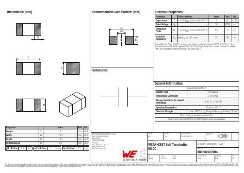
Dimensions: [mm]pl1 - Reflow2.8mmpl2 - Reflow1mmfw - Reflow1.3mmX7R0805102K050DFCT1S000885382207004X7R0805102K050DFCT1S000 885382207004T e m p e r a t u r eT pT LX7R0805102K050DFCT1S000885382207004Cautions and Warnings:The following conditions apply to all goods within the product series of MLCCs of Würth Elektronik eiSos GmbH & Co. KG:General:•This electronic component is designed and manufactured for use in general electronic equipment.•Würth Elektronik must be asked for a written approval (following the certain PPAP level procedure) before incorporating the components into any equipment in the field such as military, aerospace, aviation, nuclear control, submarine, transportation (automotive control, train control, ship control), transportation signal, disaster prevention, medical, public information network etc. where higher safety and reliability are especially required and/or if there is the possibility of direct damage or human injury.•Electronic components that will be used in safety-critical or high-reliability applications, should be pre-evaluated by the customer.•Direct mechanical impact to the product shall be prevented as material of the body, pins or termination could flake or in the worst case it could break.•Avoid any water or heavy dust on capacitors surface, which may cause electrical leakage, damage, overheating or corrosion.•Würth Elektronik products are qualified according to international standards, which are listed in each product reliability report. Würth Elektronik does not warrant any customer qualified product characteristic, beyond Würth Elektronik specifications, for its validity and sustainability over time.•The responsibility for the applicability of the customer specific products and use in a particular customer design is always within the authority of the customer. All technical specifications for standard products also apply to customer specific products.•The component is designed and manufactured to be used within the datasheet specified values. If the usage and operation conditions specified in the datasheet are not met, the body, pins or termination may be damaged or dissolved.•Do not apply any kind of flexural or compressive force onto soldered or unsoldered component.•The capacitance tolerance as specified within the datasheet is only valid on the date of delivery and according specified measurement criteria.Product specific:Storage conditions:• A storage of Würth Elektronik products for longer than 12 months is not recommended. Within other effects, the terminals may suffer degradation, resulting in bad solderability. Therefore, all products shall be used within the period of 12 months based on the day of shipment.•Do not expose the components into direct sunlight.•The storage condition in the original packaging is defined according to DIN EN 61760-2.•The environment in which the capacitors are operated and stored has to have atmospheric characteristics and must be free of dew condensation and toxic gases (e.g. chlorine, ammonia, sulfur, hydrogen sulphide and hydrogen sulfate).Operating climatic conditions:•Do not exceed the lower nor the upper specified temperature under no circumstances.•Be aware that the specified capacitance tolerance is only valid at the date of delivery.•Do not use the capacitors under high humidity, high temperature nor under high or low atmospheric pressure which may affect capacitors reliability.•Surface temperature including self-heating must be kept below the maximum operating temperature.•The temperature rise of the capacitor´s temperature compared to ambient temperature shall be below 20°C.Operating load conditions:•Operating voltage across the terminals including AC and DC peaks and AC or pulse overshooting, Vp-p, as well as irregular voltage because of resonance or switching must be below the rated voltage.•Due to self-heating the reliability of the capacitor may be reduced, if high frequency AC or pulse is applied.•Consider carefully possible specific changes of electrical characteristics like capacitance over temperature, voltage and time as well as the specific performance over frequency for the actual use conditions.Design of the PCB:•The chip capacitor shall be located to minimize any possible mechanical stress from deflection or board wrap.•It is recommended to position the chip capacitor in parallel to slits and perforations and as far away from slits, perforations, separation points, screw holes, frames and edges of the PCB to avoid mechanical stress.•The PCB design (e.g. land pattern design and grounding planes) must be evaluated for each individual circuit to achieve the optimal soldering results.Mounting:•Adjust the bottom dead center of the mounting head not to press on the PCB surface.•Provide support from the bottom side of the PCB by a support pin for minimizing the impact energy from the mounting head. Adhesive:•The adhesive should have sufficient coating and viscosity and should harden rapidly.•The adhesive should be strong enough to hold parts on the board during the mounting and solder process and should have sufficient strength at high temperatures.•The adhesive should have corrosion resistance, excellent insulation characteristics and no emission of toxic gasses nor any effect on the human body.•Do not use too much adhesive to avoid pollution of the soldering pads.Würth Elektronik eiSos GmbH & Co. KGEMC & Inductive SolutionsMax-Eyth-Str. 174638 WaldenburgGermanyTel. +49 (0) 79 42 945 - 0*******************CREATED CHECKED GENERAL TOLERANCE PROJECTIONMETHODKaS PSL DIN ISO 2768-1mDESCRIPTION TECHNICAL REFERENCEWCAP-CSST Soft TerminationMLCCX7R0805102K050DFCT1S000ORDER CODE885382207004SIZE REVISION STATUS DATE (YYYY-MM-DD)BUSINESS UNIT PAGESoldering:•The solder profile must comply with the Würth Elektronik technical soldering specification. All other profiles will void the warranty.•All other soldering methods are at the customer’s own risk.•Strong forces which may affect the coplanarity of the component’s electrical connection with the PCB (i.e. pins), can damage the part, resulting in avoid of the warranty.•Customer needs to ensure that the applied solder paste, the paste thickness and solder conditions are applicable to guarantee a sufficient solder result according to the relevant criteria of IPC-A-610.•Excessive amount of solder may lead to higher tensile force and chip cracking. Insufficient amount of solder may detach the capacitor due to defective contacts.•Do not use excessive nor insufficient flux.•Provide enough washing when water-soluble flux is used.•For reflow soldering, two times limitation is recommended.•Wave soldering is recommended only for the following case sizes: 0603 and 0805, thicknessCleaning and Washing:•Washing agents used during the production to clean the customer’s application, might damage or change the characteristics of the wire insulation body, the marking or the plating. Washing agent could have a negative effect on the long term functionality of the product.•Avoid Halogen in the flux or any contaminated flux as well as excessively high ultrasonic cleaning.Coating, molding and potting of the PCB:•If the product is potted in the costumer’s application, the potting material might shrink or expand during and after hardening. Shrinking could lead to an incomplete seal, allowing contaminants into the body and termination. Expansion could damage the body ortermination. We recommend a manual inspection after potting to avoid these effects.•When coating and molding the PCB, verify the quality influence on the capacitor.•Verify the curing temperature and assure that there is no harmful decomposing or reaction gas emission during curing.•Do not exceed the maximal temperature rise of 20°C.Handling:•After soldering, please pay attention not to bend, twist or distort the PCB in handling and storage.•Avoid excessive pressure during the functional check of the PCB.•Avoid bending stress while breaking the PCB.•After mounting, avoid piling up PCBs to avoid hitting the chip capacitor of another board.These cautions and warnings comply with the state of the scientific and technical knowledge and are believed to be accurate and reliable. However, no responsibility is assumed for inaccuracies or incompleteness.Würth Elektronik eiSos GmbH & Co. KGEMC & Inductive SolutionsMax-Eyth-Str. 174638 WaldenburgGermanyTel. +49 (0) 79 42 945 - 0*******************CREATED CHECKED GENERAL TOLERANCE PROJECTIONMETHODKaS PSL DIN ISO 2768-1mDESCRIPTION TECHNICAL REFERENCEWCAP-CSST Soft TerminationMLCCX7R0805102K050DFCT1S000ORDER CODE885382207004SIZE REVISION STATUS DATE (YYYY-MM-DD)BUSINESS UNIT PAGEImportant NotesThe following conditions apply to all goods within the product range of Würth Elektronik eiSos GmbH & Co. KG:1. General Customer ResponsibilitySome goods within the product range of Würth Elektronik eiSos GmbH & Co. KG contain statements regarding general suitability for certain application areas. These statements about suitability are based on our knowledge and experience of typical requirements concerning the areas, serve as general guidance and cannot be estimated as binding statements about the suitability for a customer application. The responsibility for the applicability and use in a particular customer design is always solely within the authority of the customer. Due to this fact it is up to the customer to evaluate, where appropriate to investigate and decide whether the device with the specific product characteristics described in the product specification is valid and suitable for the respective customer application or not.2. Customer Responsibility related to Specific, in particular Safety-Relevant ApplicationsIt has to be clearly pointed out that the possibility of a malfunction of electronic components or failure before the end of the usual lifetime cannot be completely eliminated in the current state of the art, even if the products are operated within the range of the specifications.In certain customer applications requiring a very high level of safety and especially in customer applications in which the malfunction or failure of an electronic component could endanger human life or health it must be ensured by most advanced technological aid of suitable design of the customer application that no injury or damage is caused to third parties in the event of malfunction or failure of an electronic component. Therefore, customer is cautioned to verify that data sheets are current before placing orders. The current data sheets can be downloaded at .3. Best Care and AttentionAny product-specific notes, cautions and warnings must be strictly observed. Any disregard will result in the loss of warranty.4. Customer Support for Product SpecificationsSome products within the product range may contain substances which are subject to restrictions in certain jurisdictions in order to serve specific technical requirements. Necessary information is available on request. In this case the field sales engineer or the internal sales person in charge should be contacted who will be happy to support in this matter.5. Product R&DDue to constant product improvement product specifications may change from time to time. As a standard reporting procedure of the Product Change Notification (PCN) according to the JEDEC-Standard inform about minor and major changes. In case of further queries regarding the PCN, the field sales engineer or the internal sales person in charge should be contacted. The basic responsibility of the customer as per Section 1 and 2 remains unaffected.6. Product Life CycleDue to technical progress and economical evaluation we also reserve the right to discontinue production and delivery of products. As a standard reporting procedure of the Product Termination Notification (PTN) according to the JEDEC-Standard we will inform at an early stage about inevitable product discontinuance. According to this we cannot guarantee that all products within our product range will always be available. Therefore it needs to be verified with the field sales engineer or the internal sales person in charge about the current product availability expectancy before or when the product for application design-in disposal is considered. The approach named above does not apply in the case of individual agreements deviating from the foregoing for customer-specific products.7. Property RightsAll the rights for contractual products produced by Würth Elektronik eiSos GmbH & Co. KG on the basis of ideas, development contracts as well as models or templates that are subject to copyright, patent or commercial protection supplied to the customer will remain with Würth Elektronik eiSos GmbH & Co. KG. Würth Elektronik eiSos GmbH & Co. KG does not warrant or represent that any license, either expressed or implied, is granted under any patent right, copyright, mask work right, or other intellectual property right relating to any combination, application, or process in which Würth Elektronik eiSos GmbH & Co. KG components or services are used.8. General Terms and ConditionsUnless otherwise agreed in individual contracts, all orders are subject to the current version of the “General Terms and Conditions of Würth Elektronik eiSos Group”, last version available at .Würth Elektronik eiSos GmbH & Co. KG EMC & Inductive SolutionsMax-Eyth-Str. 174638 WaldenburgGermanyTel. +49 (0) 79 42 945 - 0*******************CREATED CHECKED GENERAL TOLERANCE PROJECTIONMETHODKaS PSL DIN ISO 2768-1mDESCRIPTION TECHNICAL REFERENCEWCAP-CSST Soft TerminationMLCCX7R0805102K050DFCT1S000ORDER CODE885382207004SIZE REVISION STATUS DATE (YYYY-MM-DD)BUSINESS UNIT PAGE。
电容料位开关的技术指标是怎样的

电容料位开关的技术指标是怎样的
电容式物位开关是基于电容技术:将无线电频率施加在探头上,对周围的环境进行连续分析;
由于所有介质的介电常数和导电性均不同于空气,当探头接触到介质时所引起的微小电容量的变化被电路检测并转换成开关信号输出。
其独特的抗粘附电路只对物位改变引起的电容量的变化产生反应,从而消除了由于物料堆积产生的虚假信号。
电容料位开关主要技术指标
1、工作电源:可选AC220V±10%50~60HZ或DC24V
2、功耗:<3W
3、工作灵敏度:2~10p(即当探极从未被物料掩埋到部份被掩埋所引起的环境电容增加量≥2~10p时,继电器吸合。
)
4、回差:1~3p(即料(液)面上升引至继电器吸合后,当料(液)面下降时,继电器并不立刻释放,要降至从吸合处起,环境电容减少约1~3p距离时,继电器才释放,有效地避免了继电器在临界处频繁吸、放)
5、动作延时约3秒
6、工作环境温度:-25~45℃
7、探极工作(介质)温度:
普通型:-40~60℃
中温型:-40~200℃
8、介质压力:压力型:≤3MPa(其余型号为常压)
9、防护等级:IP65
10、输出方式:继电器触点,一组常开常闭触头。
(触点容量AC250V,0.3A;DC28V,0.;电阻负载)
标签:
电容料位开关。
万用表电容档位使用方法
万用表电容档位使用方法
宝子!今天咱来唠唠万用表电容档位咋用哈。
万用表呢,可是个很厉害的小工具。
找到电容档位,这个档位一般会有个小标识,像“C”之类的,可别找错咯。
咱先说说测电容之前的准备。
你得把万用表的表笔拿出来,就像给它伸伸胳膊一样。
然后呢,要确保你的万用表是有电的哦,要是它没电了,就像人没吃饭,啥都干不了啦。
开始测电容的时候呢,把电容从电路里取出来。
要是在电路里直接测,可能会有其他元件捣乱,测出来的结果就不准啦。
就像你想单独看一个人的本事,不能让一群人围着他,对吧?
把万用表的表笔接到电容的两个引脚。
这时候就像给电容做个小体检,表笔就是医生的听诊器。
如果你的万用表是自动量程的,那就方便多啦,它自己就会调整到合适的测量范围。
要是手动量程的呢,你就得根据电容大概的容量值来选择合适的量程。
要是选错了量程,就像给小蚂蚁用大象的秤来称重,结果肯定不对。
等一小会儿,万用表的屏幕上就会显示出电容的容量啦。
不过要注意哦,测量出来的值可能会和电容上标的标称值有点差别。
这就像人一样,没有十全十美的嘛。
如果差别不大,那电容可能就是好的。
要是差别特别大,那这个电容可能就有点小毛病啦。
还有哦,如果你的电容是电解电容,要注意它的极性。
接反了就像鞋子穿反了,肯定不合适,而且可能还会对电容或者万用表有损害呢。
宝子,万用表电容档位的使用就是这么简单又有趣。
多试几次,你就会越来越熟练啦。
就像骑自行车,刚开始可能会歪歪扭扭,骑多了就溜得很呢。
电容料位开关的技术指标是怎样的

电容料位开关的技术指标是怎样的电容料位开关作为一种重要的工业自动化设备,被广泛应用于输送带、储料仓等场合中。
它的作用是检测物料的液位、粉料的料位等信息,从而实现自动控制。
那么电容料位开关的技术指标具体是怎样的呢?本文将从以下几个方面进行讲解。
测量范围电容料位开关的测量范围是指其能够检测的物料高度范围。
不同型号的电容料位开关有不同的测量范围,一般从几毫米到几米不等。
需要根据实际应用场合的需要选择合适的测量范围,否则会影响自动控制系统的精度和稳定性。
测量精度电容料位开关的测量精度是指它能够准确检测物料高度的程度。
一般来说,电容料位开关的测量精度可以达到毫米级别。
但是,由于物料的性质、环境温度等因素的影响,测量精度有时会有所降低。
为了保证测量精度,需要对电容料位开关进行校准和调整。
灵敏度电容料位开关的灵敏度是指它能够检测到的物料高度的最小变化值。
灵敏度越高,就越能够准确地反映物料的变化,实现更加精准的自动控制。
一般来说,电容料位开关的灵敏度能够达到毫米级别,但是需要注意的是,灵敏度过高也容易受到噪声的干扰。
接触材料电容料位开关的接触材料是指它所接触到的物料所采用的材料。
不同的物料具有不同的化学性质和物理性质,因此需要根据实际情况选择合适的接触材料。
一般来说,接触材料分为金属和非金属两种。
金属材料可以耐受高温、高压、强腐蚀性等恶劣环境,但是会产生电磁干扰;非金属材料轻便、不易被腐蚀,但是对温度和压力的要求较高。
工作电压电容料位开关的工作电压是指它所能够承受的电压范围。
不同型号的电容料位开关有不同的工作电压范围,一般从几十伏到几百伏不等。
需要根据实际应用场合的需要选择合适的工作电压,否则可能会出现电路损坏或者误操作。
输出方式电容料位开关的输出方式是指它所采用的信号输出方式。
一般来说,电容料位开关的信号输出分为两种:开关量输出和模拟量输出。
开关量输出适合于对液位或料位进行二元信号控制的场合;模拟量输出适合于对物料高度进行连续调节的场合。
CLWDR2料位计说明书56版本共15页文档
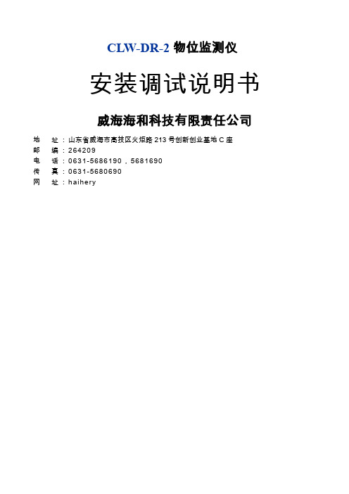
CLW-DR-2物位监测仪安装调试说明书威海海和科技有限责任公司地址:山东省威海市高技区火炬路213号创新创业基地C座邮编:264209电话:0631-5686190,5681690传真:0631-5680690网址:haihery目录一.CLW-DR-2简介1.1应用场合1.2产品特点1.3技术指标二.工作原理及特点2.1 CLW-DR系列连续物位监测仪工作原理2.2 CLW-DR系列物位监测仪特点三.安装示意图3.1安装位置图3.2安装侧面图3.3变送器接线图四.安装准备4.1安装位置的选择4.2法兰安装与定标管件的安装4.3电缆铺设五.现场安装5.1搬运5.2传感器的安装5.3变送器的安装5.4变送器的安装与接线六.调试6.1通电检查6.2 DCS设置6.3调试方法6.4调试备忘录七.故障分析八.随机配件一. CLW-DR-2简介1.1 应用场合:电力、冶金、水泥、化工等行业的煤粉仓1.2 产品特点:●自动校准,免调试,免维护●智能化判断,抗干扰能力强,信号稳定,实时连续高精度测量物位●自成阻容测量体系,工作与料仓形状无关●测量精度不受物料湿度、温度、密度及飞灰的影响●刚性传感器结构,长寿命运行●传感器耐高温、不挂粉,塌粉现象对测量无影响1.3 技术指标:●电源:AC220V±10% 功率:15W●变送器环境温度:-20~ +75︒C 防护等级IP65●绝对误差:0.1m●变送器输出:4~20mA DC●标准量程: 0~8m,特殊需要可特制●传感器耐温:长期260︒C ,瞬时600︒C二.工作原理及特点2.1 CLW-DR系列连续物位监测仪工作原理基本原理:分段连续测量原理、射频锁相分层扫描测量技术CLW-DR系列物位监测仪采用独创的分段阻容传感器,结合射频锁相测量技术、等电位技术及专用监测软件,对介质进行分段逐层扫描,实现对煤粉仓、原煤仓、灰库等粉灰及颗粒状料仓物位的实时连续监测。
- 1、下载文档前请自行甄别文档内容的完整性,平台不提供额外的编辑、内容补充、找答案等附加服务。
- 2、"仅部分预览"的文档,不可在线预览部分如存在完整性等问题,可反馈申请退款(可完整预览的文档不适用该条件!)。
- 3、如文档侵犯您的权益,请联系客服反馈,我们会尽快为您处理(人工客服工作时间:9:00-18:30)。
CLW电容料位开关
■概述
本产品采用国际上先进的射频电容技术,将容器内的物位变化量转换成电容变化量,探极作为电容的一个极板,容器壁(或辅助探极)作为另一个极板,通过电子插件把电容量的变化转换成脉冲频率的变化,将来自物位介电常数引起的信号变化给电子线路,由于电容量变化,驱动输出电路发出报警信号,从而实现料位、液位定点检测、报警或控制的目的。
■技术参数
电源电压:AC220V 50/60Hz;DC24V
相对湿度:≤85%
输出信号:一组常开、常闭触点
触点容量:AC220V,5A;DC24V,3A
环境温度:-40~+60℃
防护等级:IP65 防爆等级:ExdⅡBT4
探头材质:316不锈钢、四氟乙烯、高温塑料
功耗:≤1.5W
过程温度:普通-20~80℃;高温-25~180℃
过程压力:-0.1~4.0MPa 介电常数:ε≥1.6%
延迟时间:5秒
电气接口:M20×1.5连接方式:螺纹或法兰(见选型标记)
安装方式:顶装、侧装
■调试注意事项
CLW系列电容式物位开关灵敏度分粗调和细调
1.粗调系编码开关,他能适合对各种介质调整如矿石,孰料,水泥,煤炭,粮食,木材,麦秆,纸张。
6位编码开关由高到低调整,原则为当料位到达探极时不报警可将6位编码开关从3,2,1,顺序调整。
每拨一位开关等待5秒观察指示灯若指示灯亮说明已粗调好,(对密度高且潮湿的物料可降低其灵敏度,密度低干燥的物料可提高其灵敏度。
)
2.灵敏度细调系电位器,可调当物料粘在探极时的误动作!或者物料到达探极时精确调整,顺时针为高。
CLW系列电容式物位开关灵敏度在出厂时已调到能满足大多物位的测量。
若有特殊要求请说明!
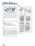
■接线方式
CLW系列电容式料位控制器(料位开关)
·1、2位为交流220V或直流24V,3、4为常闭触点。
·4、5为常开触点。