HART模块数据手册
K-AIH01 8通道带HART模拟量输入模块使用说明书

HOLLiAS MACS -K系列模块2014年5月B 版HOLLiAS MAC-K系列手册- K-AIH01 8通道带HART模拟量输入模块重要信息危险图标:表示存在风险,可能会导致人身伤害或设备损坏件。
警告图标:表示存在风险,可能会导致安全隐患。
提示图标:表示操作建议,例如,如何设定你的工程或者如何使用特定的功能。
目录1.概述 (1)2.接口说明 (3)2.1模块单元示意图 (3)2.2IO-BUS (4)2.3模块的防混淆设计 (6)2.4模块地址跳线 (7)2.5现场接口电路原理 (8)3.指示灯说明 (12)4.其他特殊功能说明 (14)4.1抗220V AC功能 (14)4.2二线制外供电功能 (15)4.3诊断功能 (16)4.4冗余功能 (18)5.工程应用 (19)5.1底座选型说明 (19)5.2应注意事项 (20)6.尺寸图 (21)7.技术指标 (21)K-AIH018通道带HART模拟量输入模块1.概述K-AIH01为K系列8通道模拟量通道隔离输入模块,支持Profibus-DP协议、HART协议。
测量范围0~22.7mA模拟信号(默认出厂量程4~20mA),同时与现场HART智能执行器进行通信,以实现现场仪表设备的参数设置、诊断和维护等功能。
可以按1:1冗余配置使用。
无需跳线就可以设置为配电或不配电工作方式,可以接二线制仪表或四线制仪表。
K-AIH01模块具备强大的过流过压保护功能,误接±30VDC和过电流都不会损坏。
同时,配合增强型底座还可以做到现场误接220V AC不损坏。
K-AIH01模块支持带点热插拔、支持冗余配置,具备完善断线、短路、超量程诊断功能,面板设计有丰富的LED指示灯,除指示模块电源、故障、通讯信息外,每个通道也有指示灯,可以方便指示各通道的断线、短路、超量程等信息。
K-AIH01模块每个通道可设置不同的滤波参数以适应不同的干扰现场。
可以根据工艺需要,配合主控制器的不同运算周期,组成可快可慢的控制回路。
HART数据格式解析2014-10-1
HART数据格式解析2014-10-141)前导码FF :5~20个字节2)定界符:只有1字节。
此字段的最高位决定该帧是长型帧还是短型帧;低三位表示了不同的帧的类型,其余位保留。
3)地址:①长帧格式地址:共5个字节(40位)。
长帧格式地址建立在设备唯一标识符的基础上,设备唯一标识符标志了每个从设备或现场仪表。
它分为三个部分:(1). 第一字节的最高位是主设备地址位,该位为1时表示基本主设备,为0时表示副主设备。
(2). 第一字节的第六位是成组模式设备,该位为1时,表示从设备处于成组模式,为0时表示从设备没有处于成组模式。
(3). 长地址的其他部分是设备的惟一标识符,共38位。
均为0表示广播地址。
②短帧格式地址:只有1字节。
为保证向后兼容性,HART协议规定只有0号通用命令支持短帧格式。
它使协议可动态地将链路上每个设备与一个短帧地址相关联。
短帧地址可在链路初始化时使用,以便快速检测链路地址空间。
短帧地址分四部分:最高位是主设备地址: 该位为1时表示主设备,为0时表示副主设备;第六位为成组模式设备位:为1时表示从设备处于成组模式,为0时,表示从设备没处于成组模式;第四、五位必须置为0;最低四位表示巡检地址。
4)命令字节:为1字节它表明该帧所封装的HART命令,命令字节值在从设备响应中原封不动地返回。
5)字节计数:为1字节它表明此字节与最后的帧校验字节之间的数据字节个数。
用于识别帧的结束。
字节长度范围应该是在0-27。
6)数据域:由整数字节的用户数据构成,长度为0-25字节7)校验字节:1个字节,一般为除开前导码和校验字节之外所有字节的异或之和8)响应码:2字节,只在从-主帧中出现。
响应码第一字节指明通信状态。
第二字节表示现场设备工作状态。
该帧数据只有在响应码第一字节的位7(b7)为0时才有效。
①响应码的第一个字节的第7位如果置位,则剩余的位包含了有关通信错误的信息;第一个字节的第7位如果复位,则剩余的位用来表示命令响应信息。
FLEX 5000 比较隔离型电流 电压 HART标准和安全I O模块使用手册说明书

FLEX 5000 類比隔離型電流/電壓/ HART 標準和安全 I/O 模組型號5094-IF8IH、5094-IF8IHXT、5094-OF8IH、5094-OF8IHXT、5094-IF4IHS、5094-OF4IHS、5094-IF4IHSXT、5094-OF4IHSXT2Rockwell Automation 出版物5094-UM007C-ZC-P - 2021年11 月FLEX 5000 類比隔離型電流/電壓/HART 標準和安全 I/O 模組使用手冊使用者重要資訊進⾏本產品的安裝、設定、操作或維護前,請閱讀本文件及其他資源一節內有關本設備安裝、設定和操作的文件。
使用者除了必須瞭解所有相關法規、法律條文與標準外,還需熟知安裝與配線說明。
舉凡安裝、調整、運作、使用、組裝、拆卸及維護等作業,均需由受訓合格的⼈員依照相關法規進⾏。
若以製造商未提及之方式使用本設備,將可能損害到製造商為本設備所提供的保護措施。
不論任何情況,Rockwell Automation Inc. 對於使用或應用此裝置而產生的間接或連帶損壞,均不負擔任何法律或賠償責任。
本⼿冊中的範例和圖表皆僅供說明之用。
由於個別安裝會有許多不同的變數及條件,Rockwell Automation, Inc. 無法對依照範例及圖⽰指⽰進⾏的實際使用狀況負責或提供賠償。
關於本⼿冊中所述之資訊、電路、設備或軟體部分,Rockwell Automation Inc. 概不承擔任何專利責任。
在取得 Rockwell Automation Inc. 書面同意之前,禁止重製本⼿冊部分或全部內容。
在整本⼿冊中,我們會在必要時使用註記,讓您瞭解安全注意事項。
標籤可能位於設備上方或內側,以提供特定預防措施資訊。
Rockwell Automation 瞭解本出版物及業界目前所使用的部分詞彙並不符合技術中與時並進的語言。
我們正積極與業界同仁合作來找出這類詞彙的替代方案,並變更我們的產品和內容。
HART475中文说明书
HART通信器是一种便携式的终端,它与采用HART通信协议的仪表一起使用,对其进行设定,更改和显示,它可监控输入/输出值和自诊断结果。
设定恒定电流的输出和调零。
当系统开动或维持操作时,只要把HART通信器接在4~20mA通信信号线上,就可以使用。
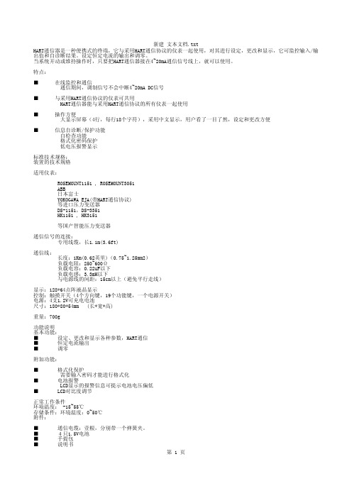
特点:■ 在线监控和通信通信期间,调制信号不会中断4~20mA DC信号■ 与采用HART通信协议的仪表可共用HART通信器能与采用HART通信协议的所有仪表一起使用■ 操作方便大显示屏幕(4行,每行18个字符),采用中文显示,用户看了一目了然,设定和更改方便■ 信息自诊断/保护功能自检查功能格式化密码保护低电压报警显示标准技术规格:装置的技术规格适用仪表:ROSEMOUNT1151 , ROSEMOUNT3051ABB日本富士YOKOGAWA EJA(带HART通信协议)等进口压力变送器DS-1151,DS-3351HK1151 , HK3151等国产智能压力变送器通信信号的连接:专用线缆,长1.1m(3.6ft)通信线:长度:1Km(0.62英里)(0.75~1.25mm2)负载电阻:250~600Ω负载电容:0.22uF以下负载电感:3.3mH以下与电源线的间距:15cm以上(避免平行走线)显示:128*64点阵液晶显示控制:触摸开关(4个方向键,19个功能键,一个电源开关)电源:4支1.2V可充电电池尺寸:180*80*54mm (长*宽*高)重量:700g功能说明基本功能:■ 设定、更改和显示各种参数,HART通信■ 恒定电流输出■ 调零附加功能:■ 格式化保护需要输入密码才能进行格式化■ 电池报警LCD显示的报警信息可提示电池电压偏低■ LCD对比度调节正常工作条件环境温度: -15~55℃存储条件:环境温度:0~50℃附件:■ 通信电缆:壹根,分别带一个弹簧夹。
■ 4只1.5V电池■ 手提包■ 说明书■ 250偶坶电阻EMC认可标准:EMI(辐射)—EN55011:1991hart475手操器 Rosemount罗斯蒙特HART475手操器 产品介绍 hart475手操器通讯器,艾默生过程管理的新型的475现场通讯器,是罗斯蒙特hart375手操器的改良升级型号,它即支持HART 通讯协议,也支持基金会现场总线通讯协议,并具有通用、可靠、便携、本安、易于升级等特点。
HART协议智能变送器操作手册
目录§1.HART协议智能变送器技术简介§2.兴业达HART协议智能变送器简介§3.基于PC的HART协议智能变送器管理系统§4.电路连接§5.用个人电脑管理HART协议智能变送器§6.用HART协议手操器管理HART协议智能变送器§7.现场调零与报警输出附录一、兴业达智能变送器HART协议命令一览表附录二:兴业达HART协议智能变送器性能参数本公司产品适用于下列产品的智能化设计:金属浮子流量计(配M7/M9指示器)1151电容式压力变送器温度变送器(Pt100,Cu50,各型号热电偶)称重式浮筒液位变送器91系列投入式压力变送器/深度液位计2390电动浮筒液位变送器电动内浮球液位变送器§1.HART协议智能变送器技术简介§1.1 工业自动化行业的大趋势---现场总线现场总线就是数字通讯一直延伸到现场仪表,使变送器、调节阀、记录仪、显示器、PLC及其它自动化设备等可通过一条总线进行双向多信息数字通讯,从而取代目前使用的4~20mA单变量单向模拟传输方式。
现场总线技术是在市场对现场仪表智能化以及全数字控制系统的需求驱动下产生的。
从技术的角度看,则是计算机技术、网络技术和控制技术发展的必然产物。
现场总线的关键标志是它能支持双向、多变量、总线式的全数字通信。
现场总线技术的出现,必将冲击现有过程控制系统的技术知识、设计方法、安装调试方法、人员培训以及产品市场的格局。
为了在这次变革中不至于被抛在后面,不同国家、不同厂商纷纷组成集团,发表各自的现场总线标准,以图率先占领市场。
比较主要的现场总线标准有Profitbus、CAN、Lonworks、SP50、ISPFIP和HART等,但由于受各自利益驱动和市场竞争,现场总线国际标准的制定进展缓慢。
§1.2 HART协议的发展虽然现场总线发展迅速,但由于4~20mA信号制的模拟设备还在大量使用中,因此从4~20mADC信号转变为现场总线全数字通讯并非一蹴而就,预计这一转变需要几十年时间。
8通道HART模拟量输入模块如何发送HART命令
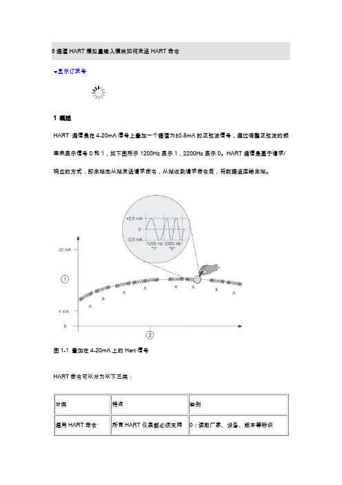
显示订货号1 概述HART 通信是在4-20mA信号上叠加一个幅值为±0.5mA的正弦波信号,通过调整正弦波的频率来表示信号0和1,如下图所示1200Hz表示1,2200Hz表示0。
HART通信是基于请求/响应的方式,即主站向从站发送请求命令,从站收到请求命令后,将数据返回给主站。
图1-1 叠加在4-20mA上的Hart信号HART命令可以分为以下三类:分类特点举例通用HART命令所有HART仪表都必须支持0:读取厂家、设备、版本等标识6ES7 153-0BA02-0XB06ES7 331-7TF01-0AB0 (E-Stand: 3)电磁流量计MAG 6000HART 通信模块FDK: 085U0226 V2.01图2-1 相关硬件命令3为HART通用命令,所有厂家的HART设备都支持该命令,通过该命令可以读取设备的输出电流,以及四个动态变量PV、SV、TV和QV,不同仪表对四个变量有不同的定义。
对图2-2 硬件组态图2-3 插入Hart模块如果该电脑上安装了SIMATIC PDM软件,可以在相应通道插入HART Field Device,这样双击该通道即可进入该仪表的参数化界面。
插入HART 6ES7331-7TF01-0AB0时,一定要插入V3.X版本的,如下图所示。
因为只有V3.X 版本模块发送HART命令时,支持表2-1所示的紧凑信息格式:图2-4 选择V3.x版本的Hart模块表2-1 紧凑信息格式注意:同样是HART模块6ES7331-7TF01-0AB0,如果E-Stand版本小于3,那么在硬件组态时需要选择下图所示的模块。
在发送HART命令时,必须使用透明信息格式(除命令0外,其它命令必须使用HART长地址,即必须包含厂家ID、设备ID等地址信息),具体操作请参考目录1。
下文以紧凑型数据格式为例进行说明。
图2-5 低版本的Hart模块设置模块属性,如下图所示:图2-6 Hart模块的参数设置设置完成之后,编译保存并下载到CPU中。
iTEMP TMT82 温度变送器,带双输入通道 HART通信协议 操作手册说明书

Products Solutions Services操作手册iTEMP TMT82温度变送器,带双输入通道HART ®通信协议BA01028T/28/ZH/25.22-00715964312022-04-04自下列版本起生效01.02(版本号)iTEMP TMT82目录Endress+Hauser 3目录1文档信息 (4)1.1文档功能 (4)1.2《安全指南》(XA) (4)1.3信息图标 (4)1.4工具图标 (5)1.5文档资料 (6)1.6注册商标 (6)2基本安全指南 (7)2.1人员要求 (7)2.2指定用途 (7)2.3工作场所安全 (7)2.4操作安全 (7)2.5产品安全 (8)2.6IT 安全 (8)3到货验收和产品标识 (9)3.1到货验收 (9)3.2产品标识 (9)3.3制造商名称和地址 (10)3.4供货清单 (11)3.5证书和认证 (11)3.6储存和运输 (11)4安装 (12)4.1安装要求 (12)4.2安装仪表 (12)4.3安装后检查 (18)5电气连接 (19)5.1接线要求 (19)5.2快速接线指南 (20)5.3连接传感器电缆 (22)5.4连接变送器 (23)5.5特殊接线指南 (23)5.6保证防护等级 (24)5.7连接后检查 (24)6操作方式 (26)6.1操作方式概览 (26)6.2操作菜单的结构和功能 (27)6.3测量值显示与操作单元 (28)6.4通过调试软件访问操作菜单 (30)7变送器的HART ®集成 (33)7.1HART 设备参数和测量值 (33)7.2HART 设备参数和测量值 (33)7.3支持的HART ®命令 (34)8仪表调试..........................368.1安装后检查..........................368.2打开变送器..........................368.3激活设置............................369维护..............................3610维修..............................3710.1概述...............................3710.2备件...............................3710.3处置...............................3711附件..............................3711.1设备专用附件........................3711.2通信专用附件........................3811.3服务专用附件........................3811.4系统产品............................3912诊断和故障排除...................4012.1故障排除............................4012.2诊断事件............................4112.3返厂...............................4512.4软件历史和兼容性概述.................4513技术参数..........................4613.1输入...............................4613.2输出...............................4713.3电源...............................4813.4性能参数............................4913.5环境条件............................5613.6机械结构............................5713.7证书和认证..........................6113.8文档资料............................6214操作菜单和菜单参数说明...........6314.1“Setup”菜单.........................7014.2“Diagnostics”菜单.....................8814.3“Expert ”菜单........................97索引. (115)文档信息iTEMP TMT824Endress+Hauser1 文档信息1.1 文档功能《操作手册》包含设备生命周期内各个阶段所需的所有信息:从产品标识、到货验收和储存,至安装、电气连接、操作和调试,以及故障排除、维护和废弃。
HART模块数据手册
LTHR2110-10V-2RN HART 通信模块 1
北京力天宏威科技 有限公司 Beijing LTHonway Technology Co.,Ltd
●满足本质安全要求,符合 RoHS 标准。 ●储存温度:-40℃~70℃。 ●相对湿度: 90%(无凝结)。
1.2 模块方框图
LTHR2110 用户手册 LTHR2110 User Manual
2. 系统级功能...................................................................................................................................... 3 2.1 工作原理................................................................................................................................... 3 2.2 通讯接口................................................................................................................................... 3 2.3 软件工具................................................................................................................................... 3
修订历史
版本 V1.0.0
罗克韦尔自动化 FLEX I O HART 模块 数据表说明书
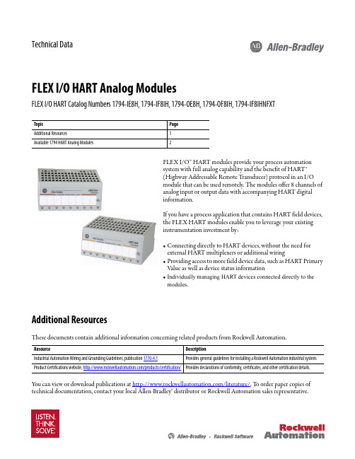
Technical DataFLEX I/O HART Analog ModulesFLEX I/O HART Catalog Numbers 1794-IE8H, 1794-IF8IH, 1794-OE8H, 1794-OF8IH, 1794-IF8IHNFXTFLEX I/O™ HART modules provide your process automation system with full analog capability and the benefit of HART® (Highway Addressable Remote T ransducer) protocol in an I/O module that can be used remotely. The modules offer 8 channels of analog input or output data with accompanying HART digital information.If you have a process application that contains HART field devices, the FLEX HART modules enable you to leverage your existing instrumentation investment by:•Connecting directly to HART devices, without the need for external HART multiplexers or additional wiring•Providing access to more field device data, such as HART Primary Value as well as device status information•Individually managing HART devices connected directly to the modules .Additional ResourcesThese documents contain additional information concerning related products from Rockwell Automation.Y ou can view or download publications at /literature/. T o order paper copies of technical documentation, contact your local Allen-Bradley® distributor or Rockwell Automation sales representative.TopicPage Additional Resources1Available 1794 HART Analog Modules2ResourceDescriptionIndustrial Automation Wiring and Grounding Guidelines, publication 1770-4.1Provides general guidelines for installing a Rockwell Automation industrial system.Product Certifications website,/products/certification/Provides declarations of conformity, certificates, and other certification details.FLEX I/O HART Analog ModulesAvailable 1794 HART Analog ModulesHART is a field proven, global industry standard with unmatched range of products and worldwide support. Using Cyclic EDT, a mechanism is used to transfer the large amount of HART data between the module and the adapter and via an additional connection to the controller for use by the end application.FLEX I/O Module TypesType Description1794-IE8H 1794-OE8H •Conformal coated modules•Provide connection to HART smart field devices such that valuable information is obtainable to help plants:–Avoid process disruptions–Improve process operations–Better manage plant assets•Customers want to bring HART data into their controllers, HMI and asset management software. These modules address this need.•These modules provide analog and HART in one module. No need for separate analog module nor separate wiring as with traditional solutions.•HART commands can be sent/received embedded in unscheduled CIP messages by a controller, HMI or third party software on ControlNet or EtherNet/IP.•Compatible with FDT-based HART device management software through use of DTMs.1794-IF8IH 1794-OF8IH 1794-IF8IHNFXT •Can be User configured to support a variety of applications including digital HART sensors and/or traditional analog sensors requiring high channel to channel isolation.•Support 8 channels of current input in multiple ranges and multiple formats. The module provides “120 VAC continuous” isolation between channels. The module will draw most of its power from a user provided external 24 VDC power supply.•RoHS compliance and extended temperature operation, a change in input filter characteristics and a number of functional changes from the the existing 1794-IF8IH module to create the 1794-IF8IHNFXT module.FLEX I/O ModulesModule Type Catalog Number PageHART Analog1794-IE8H1794-OE8H31794-IF8IH1794-OF8IH1794-IF8IHNFXT52Rockwell Automation Publication 1794-TD018A-EN-E - November 2013FLEX I/O HART Analog Modules 1794-IE8H, 1794-OE8HFLEX I/O HART Enabled Analog 8 Input Module, HART Enabled Analog 8 Output Module.Technical SpecificationsAttribute1794-IE8H1794-OE8HNumber of inputs/outputs8 single ended, non-isolated, non dedicated HART modemper channel 8 dual ended output channels referenced over sense resistors to a single commonConformally coated YesIndicators8 red fault indicators8 yellow HART communication indicators1 green power indicatorFlexbus current, 5V DC80 mAPower supplyVoltage: Current:24V DC nominal, 19.2…31.2V DC (includes 5% AC ripple) 190 mA @ 24V DCFunctional data range>17V @ 22 mA>23V @ 0 mA >15V @ 22 mA >22V @ 0 mAResolution16 bits13 bits,12.5 bits 4…20mAData format2’s complement, mA or integer values, % of full scaleConversion type Successive approximation Sigma deltaConversion rate10 ms (50 Hz) / 8.33 ms (60 Hz)10 ms all channelsStep response to 99% of full scale80 ms18 msAll channels updated to FLEX Bus≤ 10 ms≤ 13 msModule to appear approximate best/worst update time200 μs / 1600 μsTemperature drift50 ppm/C (K)80 ppm/C (K)Absolute accuracy(1)0.1% Full Scale @ 20 °C (68 °F)Acuracy drift with temperature(1)0.05% full scale for 0...55 °C (32...131 °F)0.010% full scale for 0...55 °C (32...131 °F)Calibration Factory calibratedIsolation voltage50V (continuous), Basic insulation type between field side and systemTested @ 850V AC for 1 s with no isolation between individual channelsPower dissipation, max ************************Thermal dissipation 13.5BTU/**********20.8BTU/**********Recommended terminal base1794-TB3G or 1794-TB3GSTerminal base screw torque0.8 Nm (7 lb-in.)Wire type ShieldedWire size Determined by installed terminal baseCompatibility HART 5Device supported 2 wiresNorth American temperature code T4AIEC temperature code T4Rockwell Automation Publication 1794-TD018A-EN-E - November 20133FLEX I/O HART Analog ModulesEnclosure type rating None (Open style)Dimensions, approx. (HxWxD)46 x 94 x 53 mm (1.8 x 3.7 x 2.1 in.)Publication, Installation Instructions1794-IN1081794-IN109 (1)Includes offset, gain, nonlinearity, and repeatability error terms.Environmental SpecificationsAttribute1794-IE8H1794-OE8H Temperature, operating IEC 60068-2-1 (Test Ad, Operating Cold),IEC 60068-2-2 (Test Bd, Operating Dry Heat),IEC 60068-2-14 (Test Nb, Operating Thermal Shock):-20…55 °C (-4…131 °F)Temperature, nonoperating IEC 60068-2-1 (Test Ab, Unpackaged Nonoperating Cold),IEC 60068-2-2 (Test Bb, Unpackaged Nonoperating Dry Heat),IEC 60068-2-14 (Test Na, Unpackaged Nonoperating Thermal Shock):-40…85 °C (-40…185 °F)Relative humidity IEC 60068-2-30 (Test Db, Unpackaged Nonoperating Damp Heat):5…95% noncondensingVibration IEC 60068-2-6 (Test Fc, Operating):2 g @ 10…500 HzShock, operating IEC 60068-2-27 (Test Ea, Unpackaged Shock):15 gShock, nonoperating IEC 60068-2-27 (Test Ea, Unpackaged Shock):15 gEmissions CISPR 11: Group 1, Class A (with appropriate enclosure)ESD immunity IEC 61000-4-2:6kV contact discharges8 kV air dischargesRadiated RF immunity IEC 61000-4-3:10V/m with 1 kHz sine-wave 80% AM from 80...2500 MHz1V/m with 1 kHz sine-wave 80% AM from 2500...2700 MHzEFT/B immunity IEC 61000-4-4:±2 kV @ 5 kHz on power ports±2 kV @ 5 kHz on signal portsSurge transient immunity IEC 61000-4-5:±1 kV line-line(DM) and ±2 kV line-earth(CM) on power ports±2 kV line-earth(CM) on shielded portsConducted RF immunity IEC 61000-4-6:10V rms with 1 kHz sine-wave 80% AM from 10 kHz…80 MHz IEC 61000-4-6:10V rms with 1 kHz sine-wave 80% AM from 150 kHz…80 MHzTechnical SpecificationsAttribute1794-IE8H1794-OE8H4Rockwell Automation Publication 1794-TD018A-EN-E - November 2013Rockwell Automation Publication 1794-TD018A-EN-E - November 20135FLEX I/O HART Analog Modules1794-IF8IH, 1794-OF8IH, 1794-IF8IHNFXTFLEX I/O HART Enabeld Isolated Analog 4 Input Module, FLEX I/O HART Enabled Isolated Analog 4 Input Extreme Temperature ModuleCertificationsCertification (1)(When marked on product)(1)See the Product Certification link at /products/certification/ for Declaration of Conformity, Certificates, and other certification details.1794-IE8H1794-OE8Hc-UL-us UL Listed Industrial Control Equipment, certified for US and Canada. See UL File E65584.UL Listed for Class I, Division 2 Group A,B,C,D Hazardous Locations, certified for U.S. and Canada. See UL File E194810.CEEuropean Union 2004/108/IEC EMC Directive, compliant with:EN 61326-1; Meas./Control/Lab., Industrial Requirements EN 61000-6-2; Industrial Immunity EN 61000-6-4; Industrial EmissionsEN 61131-2; Programmable Controllers (Clause 8, Zone A & B)C-Tick Australian Radiocommunications Act, compliant with:AS/NZS CISPR 11; Industrial EmissionsExEuropean Union 94/9/EC ATEX Directive, compliant with:EN 60079-15; Potentially Explosive Atmospheres, Protection "n"EN 60079-0; General Requirements II 3 G Ex nA IIC T4 XKCKorean Registration of Broadcasting and Communications Equipment, compliant with:Article 58-2 of Radio Waves Act, Clause 3Technical SpecificationsAttribute1794-IF8IH 1794-OF8IH1794-IF8IHNFXTNumber of inputs/outputs 8 single-ended isolated Indicators 1 red/green power/status indicator Flexbus current, 5V DC 80 mAPower supply Voltage Current 24V DC nominal, 19.2…31.2V DC (includes 5% AC ripple)190 mA @ 24V DC24V DC nominal, 19.2…31.2V DC (includes 5% AC ripple)450 mA @ 24V DC24V DC nominal, 19.2…31.2V DC (includes 5% AC ripple)190 mA @ 24V DCCurrent terminal4…20 mA (user configurable)0…20 mA (user configurable)0 mA output until product is configured Resolution16 bits - unipolar15 bits plus sign - bipolar 0.320 μA/cnt unipolar 0.640 μA/cnt bipolar 16 bits - unipolar 0.305 μA/cnt unipolar16 bits - unipolar 0.3052 μA/cnt unipolar 0.6104 μA/cnt bipolarData formatEngineering Units (2)Percent of Full Scale RAW/Proportional Count Conversion type Sigma Delta16 bits digital to analog converter Sigma DeltaConversion rate Refer to update rate table in publication, 1794-IN11510 msRefer to update rate table in publication,1794-IN134Resistance249 Ω ± 1%0 … 750 Ω standard249 Ω ± 1%6Rockwell Automation Publication 1794-TD018A-EN-E - November 2013FLEX I/O HART Analog ModulesNormal mode rejection ratio - voltage or current terminal>70 dB @ 50/60 Hz (4.17 Hz ADC conversion rate)>65 dB @ 50/60 Hz (10.0 Hz ADC conversion rate)>75 dB @ 50 Hz (16.7 Hz ADC conversion rate)>85 dB @ 60 Hz (19.6 Hz ADC conversion rate)>70 dB @ 50/60 Hz (4.17 Hz ADC conversion rate)>65 dB @ 50/60 Hz (10.0 Hz ADC conversion rate)>75 dB @ 50 Hz (16.7 Hz ADC conversion rate)>70 dB @ 60 Hz (19.6 Hz ADC conversion rate)Common mode rejection ratio >60 dB @ 50 Hz >60 dB @ 60 HzStep response to 99% full scale to current terminal4.17 Hz conversion rate = 480 ms 10.0 Hz conversion rate = 200 ms 16.7 Hz conversion rate = 120 ms 19.6 Hz conversion rate = 101 ms 62 Hz conversion rate = 32 ms 470 Hz conversion rate = 4 ms -4.17 Hz conversion rate = 480 ms 10.0 Hz conversion rate = 200 ms 16.7 Hz conversion rate = 120 ms 19.6 Hz conversion rate = 101 ms 62 Hz conversion rate = 32 ms 123 Hz conversion rate = 17 ms 242 Hz conversion rate = 14 ms Absolute accuracy (1)0.1% full scale @ 25 °C ± 0.1% full scale @ 25 °C ± 0.35% full scale @ 0…55 °C 0.1% full scale @ 25 °C Accuracy drift with temperature (1)0.4% full scale for 0…55 °C 0.008 % /°C0.0038 % full scale/°C0.55% full scale for -25…70 °CCalibration Factory calibrated.Maximum overload 32 mA continuousIsolation voltage120V (continuous), Basic Insulation TypeType tested @ 1000V AC for 60 s, between User power to system, channel to system, and channel to channel 120V (continuous), Basic Insulation TypeType tested @ 1500V AC for 60 s, between channel to power, channel to system, and power to system, and channel to channel. Power dissipation, max **********10.8 W @ 24V DC ************Thermal dissipation 20.5BTU/**********36.8 BTU/hr @ 24V DC 16.4BTU/**********Recommended terminal base 1794-TB3, 1794-TB3S Terminal screw torque 0.8 Nm (7 lb-in.)Wire type ShieldedWire size Determined by installed terminal base Compatibility HART 5HART 5, 6, 7Device supported 2, 3, 4 wires North American temperature code T4T5IEC temperature code T4Enclosure type rating None (open-style)Dimensions, approx. (HxWxD)with module installed in base 94 x 94 x 66 mm (3.7 x 3.7 x 2.6 in.)Publication,Installation Instructions1794-IN1151794-IN1201794-IN134(1)Includes offset, gain, non-linearity and repeatability error terms.(2)Engineering Units apply to HART data only.Technical SpecificationsAttribute1794-IF8IH1794-OF8IH1794-IF8IHNFXTFLEX I/O HART Analog ModulesEnvironmental SpecificationsAttribute1794-IF8IH1794-OF8IH1794-IF8IHNFXTTemperature, operating IEC 60068-2-1 (Test Ad, Operating Cold),IEC 60068-2-2 (Test Bd, Operating Dry Heat),IEC 60068-2-14 (Test Nb, Operating Thermal Shock):0…55 °C (32…131 °F) -25…70 °C (-13…158 °F)Temperature, nonoperating IEC 60068-2-1 (Test Ab, Unpackaged Nonoperating Cold),IEC 60068-2-2 (Test Bb, Unpackaged Nonoperating Dry Heat),IEC 60068-2-14 (Test Na, Unpackaged Nonoperating Thermal Shock):-40…85 °C (-40…185 °F)Relative humidity IEC 60068-2-30 (Test Db, Unpackaged Nonoperating Damp Heat):5…95 % noncondensingVibration IEC 60068-2-6 (Test Fc, Operating):5 g @ 10…500 HzShock, operating IEC 60068-2-27 (Test Ea, Unpackaged Shock) :20 g30 gShock, nonoperating IEC 60068-2-27 (Test Ea, Unpackaged Shock):25 g50 gEmissions CISPR 11: Group 1, Class AESD immunity IEC 61000-4-2:6 kV contact discharges8 kV air dischargesRadiated RF immunity IEC 61000-4-3:10V/m with 1kHz sine-wave 80% AM from 80… 2000 MHz10V/m with 200Hz 50% Pulse 100% AM @ 900 MHz10V/m with 200Hz 50% Pulse 100% AM @ 1890 MHz3V/m with 1kHz sine-wave 80% AM from 2000…2700 MHz IEC 61000-4-3:10V/m with 1kHz sine-wave 80% AM from 80… 2000 MHz 10V/m with 200Hz 50% Pulse 100% AM @ 900 MHz10V/m with 200Hz 50% Pulse 100% AM @ 1890 MHz10V/m with 1kHz sine-wave 80% AM from 2000…2700 MHzEFT/B immunity IEC 61000-4-4:±3 kV @ 5 kHz on signal ports IEC 61000-4-4:±3 kV @ 5 kHz on signal ports ±3 kV @ 5 kHz on power portsSurge transient immunity IEC 61000-4-5:±2 kV line-earth(CM) on shielded ports IEC 61000-4-5:±1 kV line-line(DM) and ±2 kV line-earth(CM) on power ports ±2 kV line-earth(CM) on shielded portsConducted RF immunity IEC 61000-4-6:10V rms with 1 kHz sine-wave 80% AM from 150 kHz…80 MHzCertificationsCertification(1)(When marked on product)1794-IF8IH1794-OF8IH1794-IF8IHNFXTc-UL-us UL Listed Industrial Control Equipment, certified for US and Canada. See UL File E65584.UL Listed for Class I, Division 2 Group A,B,C,D Hazardous Locations, certified for U.S. and Canada. See UL File E194810.CE European Union 2004/108/IEC EMC Directive, compliant with:EN 61326-1; Meas./Control/Lab., Industrial RequirementsEN 61000-6-2; Industrial ImmunityEN 61000-6-4; Industrial EmissionsEN 61131-2; Programmable Controllers (Clause 8, Zone A & B)C-Tick Australian Radiocommunications Act, compliant with:AS/NZS CISPR 11; Industrial EmissionsRockwell Automation Publication 1794-TD018A-EN-E - November 201378Rockwell Automation Publication 1794-TD018A-EN-E - November 2013FLEX I/O HART Analog ModulesExEuropean Union 94/9/EC ATEX Directive, compliant with:EN 60079-15; Potentially Explosive Atmospheres, Protection "n"EN 60079-0; General Requirements II 3 G Ex nA IIC T4 Gc TÜV -TÜV Certified for Functional Safety (2): Capable of SIL 2 KCKorean Registration of Broadcasting and Communications Equipment, compliant with:Article 58-2 of Radio Waves Act, Clause 3-(1)See the Product Certification link at /products/certification/ for Declaration of Conformity, Certificates, and other certification details.(2)When used with specified firmware revisions.CertificationsCertification (1)(When marked on product)1794-IF8IH1794-OF8IH1794-IF8IHNFXTFLEX I/O HART Analog Modules Notes:Rockwell Automation Publication 1794-TD018A-EN-E - November 20139Allen-Bradley, FLEX I/O, RSLogix 5000, Rockwell Software, Rockwell Automation, and LISTEN. THINK. SOLVE are trademarks of Rockwell Automation, Inc.T rademarks not belonging to Rockwell Automation are property of their respective companies.Publication 1794-TD018A-EN-E - November 2013Copyright © 2013 Rockwell Automation, Inc. All rights reserved.Important User InformationSolid-state equipment has operational characteristics differing from those of electromechanical equipment. SafetyGuidelines for the Application, Installation and Maintenance of Solid State Controls (publication SGI-1.1 available from your local Rockwell Automation sales office or online at /literature/) describes some important differences between solid-state equipment and hard-wired electromechanical devices. Because of this difference, and also because of the wide variety of uses for solid-state equipment, all persons responsible for applying this equipment must satisfy themselves that each intended application of this equipment is acceptable.In no event will Rockwell Automation, Inc. be responsible or liable for indirect or consequential damages resulting from the use or application of this equipment.The examples and diagrams in this publication are included solely for illustrative purposes. Because of the many variables and requirements associated with any particular installation, Rockwell Automation, Inc. cannot assume responsibility or liability for actual use based on the examples and diagrams.No patent liability is assumed by Rockwell Automation, Inc. with respect to use of information, circuits, equipment, or software described in this manual.Reproduction of the contents of this manual, in whole or in part, without written permission of Rockwell Automation, Inc., is prohibited.Documentation FeedbackY our comments will help us serve your documentation needs better. If you have any suggestions on how to improve this document, complete this form, publication RA-DU002, available at /literature/.Rockwell Otomasyon Ticaret A.Ş., Kar Plaza İş Merkezi E Blok Kat:6 34752 İçerenköy, İstanbul, T el: +90 (216) 5698400。
Festo CPX-HART模块配置与TIA Portal及PROFINET教程说明书
Application NoteCPX-HART module configuration withPortal TIA and PROFINETHow to configure CPX-4AE-4AA-H module using Siemens TIACPX-4AE-4AA-H Portal® with PROFINET.100183Title ............................................................................................... C PX-HART module configuration with Portal TIA Version ............................................................................................................................................................. 1.10 Document no. . (100183)Original .................................................................................................................................................................en Author ............................................................................................................................................................. F estoLast saved ............................................................................................................................................ 24.09.2018Copyright NoticeThis documentation is the intellectual property of Festo AG & Co. KG, which also has the exclusive copyright. Any modification of the content, duplication or reprinting of this documentation as well as distribution to third parties can only be made with the express consent of Festo AG & Co. KG.Festo AG & Co KG reserves the right to make modifications to this document in whole or in part. All brand and product names are trademarks or registered trademarks of their respective owners.Legal NoticeHardware, software, operating systems and drivers may only be used for the applications described and only in conjunction with components recommended by Festo AG & Co. KG.Festo AG & Co. KG does not accept any liability for damages arising from the use of any incorrect or incomplete information contained in this documentation or any information missing therefrom.Defects resulting from the improper handling of devices and modules are excluded from the warranty.The data and information specified in this document should not be used for the implementation of safety functions relating to the protection of personnel and machinery.No liability is accepted for claims for damages arising from a failure or functional defect. In other respects, the regulations with regard to liability from the terms and conditions of delivery, payment and use of software of Festo AG & Co. KG, which can be found at /sp and can be supplied on request, shall apply.All data contained in this document do not represent guaranteed specifications, particularly with regard to func-tionality, condition or quality, in the legal sense.The information in this document serves only as basic information for the implementation of a specific, hypothet-ical application and is in no way intended as a substitute for the operating instructions of the respective manufac-turers and the design and testing of the respective application by the user.The operating instructions for Festo products can be found at /sp.Users of this document (application note) must verify that all functions described here also work correctly in the application. By reading this document and adhering to the specifications contained therein, users are also solely responsible for their own application.(Festo AG & CO. KG, D-73726 Esslingen, 2018)Internet: E-Mail: *******************************Table of contents1Components/Software used (5)1.1Software (5)1.2Hardware (5)1.3Documentation (5)2Application Description (6)3Product-specific terms and abbreviations (7)4Installation (8)4.1Hardware Setup (8)4.1.1CPX-FB34 (8)4.1.2CPX-4AE-4AA-H (9)4.1.3Siemens S7-1200 and TMT-182 (9)4.2Electrical Connection (9)4.2.1CPX-4AE-4AA-H and TMT-182 Temperature Transmitter (9)4.2.2CPX-FB34 and Siemens S7-1200 (10)5Commissioning (11)5.1Hardware configuration into TIA Portal (11)5.1.1Download for GSDML file (11)5.1.2Installation for GSDML file into the TIA Portal (11)5.1.3Inserting the CPX in the TIA Portal Project (13)5.1.4PROFINET network assignment (15)5.1.5Hardware configuration for CPX into TIA Portal (16)5.2Accessible Parameters from TMT-182 (17)5.3Module Parametrization in “HW configuration” (18)6Operation (19)6.1Checking address allocation to CPX-4AE-4AA-H (19)6.2Process Image and addressing for TMT-182 with 2AI2AO-H 4HV (19)6.3Add variables using TIA Portal “Watch Table” (20)6.4Online Values and comparison with DTM drive (21)7Technical appendix (22)7.1Module Parametrization using “DPV1 Direct Message” (22)7.1.1Needed resources from Siemens (22)7.1.2RDREC and WDREC parameters (23)7.1.3Creating a Database (DB) for exchange variables (24)7.1.4Accessible module parameters (25)Components/Software used 1Components/Software used1.1SoftwareTable 1.1: Software used1.2HardwareTable 1.2: Components used1.3DocumentationThis documentation intends to deliver supplementary information regarding the following documentations: •CPX-4AE-4AA-H (8083252):/net/en-gb_gb/SupportPortal/Files/491948/CPX-4AE-4AA-H_2017-12_8083252g1.pdf•P.BE-CPX-PNIO-EN (548760):/net/en-gb_gb/SupportPortal/Files/407977/CPX-FB33_35_41_2014-10d_548760g1.pdfApplication Description2Application DescriptionThis Application Note explains about configuration for module CPX-4AE-4AA-H (8059847) with Siemens TIA Por-tal® using CPX-FB34 as PROFINET remote I/O.For exemplary purposes, a Temperature Transmitter from Pepperl+Fuchs Model TMT182® as well as your DTM Driver and PACTware® FDT Application has been used for better understanding about specific behaviors for data format, data exchange and commissioning of a HART network using the module CPX-4AE-4AA-H (8059847).In this document we will describe good practices and possible different configurations for applications that re-quires uses from CPX-P HART module and TIA Portal.Product-specific terms and abbreviations 3Product-specific terms and abbreviationsTable 3.1: Product-specific terms and abbreviationsInstallation4Installation4.1Hardware SetupWarningThis application note is entirely based in the following HW configuration as describedAny possible modification into the hardware can be consider as a possible troubleshoot step. For this Application Note, we have to setup the Hardware as described below:4.1.1CPX-FB34The required configuration for the CPX-FB34 is:-Remote I/O operating mode : (DIL 1.1 OFF ; DIL 1.2 OFF) ;-Status bit switched off : (DIL 2.1 OFF; DIL 2.2 OFF)NoteThis configuration is valid for CPX-FB33 and CPX-FB35 as well.Installation4.1.2CPX-4AE-4AA-HThe required configuration for the CPX-FB34 is:- 2 HART enable Input and 2 HART enable Outputs (2AEAA-H + 4HV);Table 4.1: DIL switches variants for HART Module4.1.3Siemens S7-1200 and TMT-182This devices do not require any hardware setup for this Application Note.4.2Electrical ConnectionFor this application it was used the following connections between devices:4.2.1CPX-4AE-4AA-H and TMT-182 Temperature TransmitterNoteThe TMT-182 is an passive power transmitterFor further information about TMT-182 and possible functions , please, contact the manufacturer.InformationFurther information about how to connect your transmitter into CPX-4AE-4AA-H is explained at:CPX-4AE-4AA-H Manual Cap.7.5 ( Connection scenarios ).Installation4.2.2CPX-FB34 and Siemens S7-1200There are two RJ45 push-pull sockets (AIDA-compliant) on the CPX-M-FB34 for the network connection:Table 4.2: Pin allocation of the network interfaces of the bus node CPX-M-FB34 (RJ45)Device IP Address PROFINET NameCPX-FB34 Remote I/O 192.168.0.14 CPXS7-1200 CPU 192.168.0.1 S71200Table 4.3: Device ConfigurationInformationFurther information about how to assign name and IP address for CPX is explained at:CPX-FB34 Manual Cap.2.6 ( Basic hardware configuration ).Commissioning 5Commissioning5.1Hardware configuration into TIA Portal5.1.1Download for GSDML file•Open the browser;•Open the link below ;https:///net/en-gb_gb/SupportPortal/default.aspx?q=GSDML&tab=4&s=t#result •Download the “PROFINET GSDML file for CPX“clicking in “Device Description Files”;•Once that you downloaded, extract the file in a known place into your computer.5.1.2Installation for GSDML file into the TIA Portal•Create a project in TIA Portal and select your PLC;•Open the Project Tree and Select “Device Configuration”;•Go to : Options -> Manage general station description files (GSD);Commissioning•In source path, select where the extracted files are located;•Select all Files and clink at “Install”;•You will get a message when is done.NoteFor older GSDML versions is the same procedure.Commissioning5.1.3Inserting the CPX in the TIA Portal Project•Double Click in “Device configuration”;•Select “network view” Tab;•Open the guide “Hardware Catalog”;•Search inside of PROFINET IO device catalog for :•Valves -> Festo AG & CO. KG -> Festo CPX Terminal -> CPX REV.30WarningThe module CPX-4AE-4AA-H is compatible with CPX GSD REV.30 or later.Any other older version has no compatibility with the HART Module.Commissioning•Drag and drop the terminal “CPX Rev. 30 “ at “network view”:•The terminal should show as below:•Commissioning5.1.4PROFINET network assignment•Click on “Not assignment” at CPX system:•Select the Master port (in example: PLC_1.PROFINET interface_1)•Your CP system will be directly addressed for the available PROFINET network.NoteThis the PLC1_PROFINET interface_1 is automatically generated by default.You can choose other subnet using following steps:•Click at the PROFINET Master ;•Go to the tab : Network settings → PROFINET Interface ;•Add s subnet clicking at section Ethernet Addressing → Add Subnet .Commissioning5.1.5Hardware configuration for CPX into TIA Portal•Double-click in to your CPX System at “Network View”;•Select your modules dragging from the “Hardware Catalogue” according with your actual configuration for the slave the modules have different configurations based on your DIL switches (See more at → 4.1.2) This application note contains the following configuration:-CPX-FB34 PNIO (CPX PROFINET Slave without Status configuration);-2AI2AO-H 4HV (2 Inputs , 2 Outputs + 4 Slots for IEEE Routing);•Click in CPX Module•Go to General → Module Parameters;•Change the “Visualization of analogue variables” to “MOTOROLA (MSB-LSB)”;NoteThis is an additional step due to addressing behavior between devices.The CPX uses INTEL addressing and Siemens has MOTOROLA byte order.For different PROFINET master, this can vary.Commissioning5.2Accessible Parameters from TMT-182Accessing the DTM from TMT-182 using PACTware you have the following variables to access through IEEE Routing:The available values for TMT-182 are:Table 5.1: Available variables from TMT-182The Analog Variables has a fast update rate and must be configured direct in parameters from the TMT-182. Normally in transmitters they are fully scalable or exchangeable for other variables , depending of the complexity of the measured value and the application.The IEEE Routing variables have a slow update rates due to protocols overhead and can be used for monitoring and diagnosis purposes from the transmitter.The CPX-4AE-4AA-H allows you to read up to 4 IEEE routing variables (4 bytes each variable : 16 Bytes total).InformationFurther information about the parameters and data allocation is explained at:CPX-4AE-4AA-H Manual Cap.8 (Commissioning).Commissioning5.3Module Parametrization in “HW configuration”This configuration allows the PROFINET Master to overwrite configuration via DPV1 during the start-up from the Slave and this activates the HART module for data exchange.•Click at “2AI2AO-H 4HV”;•Go to “Gen eral -> Module Parameters”At “Module Parameters” you can configure this application note we are using the following configuration:Table 5.2: Parameter list for configurationNoteAll the variables not mentioned in this part of the document you can assume that they are in defaultvalueOperation 6Operation6.1Checking address allocation to CPX-4AE-4AA-HYou can c heck the address allocation into your CPX using “Device View”.6.2Process Image and addressing for TMT-182 with 2AI2AO-H 4HVThe Process image for the CPX-4AE-4AA-H depends of which DIL configuration has been made for the application. This application uses the Processing Image for 2AI2AO-H 4HV as follow:SW CH ”y” =Output Word for Channel “y” (Exchange via Analog Channel)HV ”z” = HART Variable “z” (via IEEE Routing)n/a = not appliable for this Application Note, but still mapped“-“ = not mapped , used in other types of configuration.Table 6.1: 2AI2AO-H 4HV variant processing image for CPX-4AE-4AA-H.Operation6.3Add variables using TIA Portal “Watch Table”•Open “Project Tree”;•Click at “Watch and force tables”;•Double click at “add new watch table” icon;•The Table will appears empty;•Fulfill the table as mentioned at Cap. 6.2;•Perform download in your system and make sure to be at RUN MODE;NoteThis step may vary for different CPU´s from SiemensMake sure that your system is with the correct downloaded program and at RUN MODE.Operation6.4Online Values and comparison with DTM drive•When in “Online Mode”, open “Watch Table”;•Click into “Monitor All” Icon ;•The Values will appears at “Monitor Value” Column:Values outside of the measurement range will be with the value 0xFFFF. Make sure that your variables are being read properly:•Open your DTM drive and compare the values between TIA Portal.NoteThe values for the Process Value are scaled to 4-20 mA (linear scaled)You can change the scale simply going into CPX-4AE-4AA-H at “Device View” and modifying thescale as your application request.InfoFurther information about scaling is explained at:CPX-4AE-4AA-H Manual Cap.8.5 (Data format and range of the Actual Values)Technical appendix7Technical appendix7.1Module Parametrization using “DPV1 Direct Message”Siemens system allows you to write parameters for your CPX using DPV1 parameter channel through SFC blocks and programming. In this section we will explain other possible way to parametrize your application with S7-1200 using DPV1 Direct Message.You can use different parameters for CPX-4AE-4AA-H and here is some possible application for this parameters: •Change the type of scaling on-fly from the module;•Change the type of signal (4-20mA, 4-20ma HART; “Disable for maintenance”);•Change HART variables that you would like to get from your Transmitter (Change SV to TV or QV);•SCS and Fail-Safe Behavior;7.1.1Needed resources from SiemensFor this application you will need the following resources from TIA Portal:•RDREC – block to Read parameters•WDREC – block to Read parameters•DB – Database Creation for Change / Read your ParametersYou will find both at the catalogue function at “Extended Instructions”:Technical appendix7.1.2RDREC and WDREC parametersThe SFC blocks WRRED and RDREC have common parameters to exchange data as described below:Parameter Declaration Value DescriptionID Input – HW_IO See HW-ID Based on HW configuration. You can find this number at:Devices & Networks → Device Overview →Click at the “CPX-System” →Click into your “CPX-Module” → Properties →HWIdentification:INDEX Input – DINT 21 21 represents “Module Specific Parameters“. See TableMLEN/LEN Input – UINT 66 Size of read/write parameters you want to get (64 bytes) + 2Header bytes for identification (=66 bytes). The parameters will beoffset as described at table due to the header identification. RECORD InOut - VARIANT DB Block Variable that will be transfer with the parameters. See →cap.7.1.3 Table 7.1: Parameters for RDREC AND WDREC.WarningThis for different Siemens CPU’s you have different type of configurations for the parameter (ID).Make sure that you are using the right one:•For S7-1200/S7-1500 - ID PARAMETERHardware identifier of the hardware module (DP/PROFINET IO)The number is assigned automatically and is stored in the properties of the module or of the in-terface in the hardware configuration.•For S7-300/S7-400Logical address of the DP slave/PROFINET IO component (module or sub-module).For an output module, bit 15 has to be set (for example, for address 5: ID:=DW#16#8005).For ( a mixed module, the lower of the two ( addresses must be specified).InfoFor additional information you can use TIA portal help with keywords → WRRED ; RDREC ; DPV1.Technical appendix7.1.3Creating a Database (DB) for exchange variables•Right Click at “Program Blocks” in “Project Tree”;•Select a “Data Block” and Type” Global Block”;•Create an Variable type “Array [0…xx] of Byte” whereas “xx” need to be at least the quantity of exchangeable parameters + 2 Header Bytes;InfoFurther information about “Device Specific Parameters” for CPX-4AE-4AA-H explained at:CPX-4AE-4AA-H Manual Cap.8.4 (Parameterization)Technical appendix 7.1.4Accessible module parametersTable 7.2: Accessible INDEX data.1) First 2 Bytes are HeadersTable 7.3: Database Parameters and Specific Module Parameters for CPX-4AE-4AA-H.。
5437 二线制 HART 7 温度变送器 产品手册说明书

C O M M U N I C A T I O N P R O T O C O LNo. 5437V102-CNProduct version: 01.00.00-01.99.99安全栅 | 通讯接口 | 多功能 | 隔离器 | 数显表产品手册 5437二线制 HART 7 温度变送器基于微处理器技术研发的 6 mm 隔离器,小巧精致、响应迅速、品质一流,以极低的总拥有成本为专用应用提供卓越性能和抗电磁干扰。
可水平或垂直安装,装置间无需间隙。
我们采用最严格的安全标准来检验产品,以期提供最安全的信号。
秉承创新精神,我们已经在 SIL 2 全面评估本质安全型接口方面取得了开创性成就,其既高效又经济,效果卓著,成效斐然。
模拟量和数字量本质安全栅种类齐全,同时提供多种输入输出。
这使得 PR 标准成为一项易于实施的现场检验标准。
在大型项目安装过程中,新背板方案大大简化安装和布线,且能与标准 DCS 系统无缝集成。
数显表系列以其灵活性和稳定性著称。
该设备系列几乎满足过程信号读数显示的所有需求,并具有通用的输入和供电能力。
无论哪种行业,无论环境条件何其苛刻,该设备均能实时测量过程值并提供用户友好型界面和值得信赖的继电器信号。
我们提供经济实惠、使用方便、面向未来的通讯接口,以便您能够访问所安装的 PR 产品。
所有接口均可拆卸,并带有屏幕和按钮,可以显示过程值/诊断值和对参数进行配置。
产品特定功能包括通过 Modbus 和蓝牙进行通讯,以及使用我们的便携式设备主管 (PPS) 应用程序进行远程访问,可用于 iOS 和 Android 。
单品为多功能系列产品,可涵盖大量现场应用,可轻而易举按照您的现场标准进行配置。
此种单品可适用多种应用方式,既节省安装和培训时间,又大大简化库存备件管理。
该设备专为长期信号精度高、功耗低、抗电噪声优异、编程简单而设计。
温度变送器和温度传感器系列产品,提供从温度测量点到系统控制一站式信号解决方案,从而在最大程度上保证信号的完整性。
手操器HART 菜单树中文

H ART 375 HART® 协议手持通信器HART375手持器注意事项!注意 1:在使用HART手持器之前请阅读本手册。
为了您个人和系统的安全,在使用和维修产品之前请确信您已经理解了本手册之全部内容。
注意2:在阳光下爆晒本设备,会缩短液晶显示器的寿命。
注意3:在长时间不使用本设备时,建议取出设备内的电池,以免因电池漏液损坏本设备。
目录一、使用指南 (5)1.1 简介 (5)1.2 手持器连接 (5)1.3 打开手持器 (6)1.4 常用功能指导 (6)1.4.1监视变量(读取检测值) (6)1.4.2设定主变量单位 (6)1.4.3设定量程上限 (7)1.4.4设定量程下限 (7)1.4.5设定阻尼 (7)1.4.6输出电流校准 (7)1.4.7主变量调零 (7)二、技术指标 (8)2.1 外形尺寸 (8)2.2 HART接口部分 (8)2.3 PC接口部分 (8)2.4 功耗指标 (8)2.5 电池的使用 (8)2.6 环境温度要求 (9)2.7 液晶显示屏 (9)三、按键说明 (9)3.1 开/关键 (9)3.2向上箭头键 (10)3.3向下箭头键 (10)3.4向左箭头键和返回上一级菜单键 (10)3.5向右箭头键和选择键 (10)3.6确认键 (10)3.7文字数字和转换键 (10)3.8使用转换键来输入数据 (11)四、功能介绍 (11)4.1主菜单 (11)4.2 在线菜单 (11)4.3 读取过程变量 (12)4.4 诊断/服务 (12)4.5 基本设置 (12)4.6 详细设置 (13)4.7 其他功能介绍 (16)4.7.1上电自动轮询仪表 (16)4.7.2 下装 (16)4.7.3 显示电池电量 (16)4.7.4 轮询 (17)五、常见故障排除 (17)5.1 手持器不能找到仪表 (17)5.2 按手持器电源开关无显示 (17)5.3 不支持设备的特殊功能 (17)附录1 ROSEMOUNT 1151树形菜单 (19)附录2 ROSEMOUNT 3051树形菜单 (21)一、使用指南1.1 简介H ART375 HART手持器是支持HART协议设备的手持通信器,它可以对所有符合HART协议的设备进行配置、管理和维护。
FM148RH 8通道电流冗余输入(HART)模块使用说明书
In+
2-7 通道的接线 与1 通道相同
In-
AI 信号,同一处设备来的信号尽量集中在一个模块上。
现场
电缆层
FM131A/F M 148H
安全栅的使用
图 3-3 FM148RH 四线制电流信号的连接
FM148RH 模块在化工或其他防爆场合使用时要求本安接地,则必须使用安全栅。请使用符合
本质安全型防爆规格且获得可在危险区使用认证的安全栅。对于 HART 仪表,齐纳安全栅全部适用;
����
� � � � �� � � � �
����������
�� �� �� �� �� �� �� �� �� �� �� �� �� �� �� �� � � � �
� � � �� ㈱ � � � �
����������
����
� �� � �� � �� � �� � �� � �� � �� � �� � � � �
270Ω
外供电输出限流
29mA
通道故障诊断
0~22mA 量程支持短路、超高限、超低限、断线四种故障诊断 功能
热启动数据处理
保持原数据
带电插拔
支持
指示灯
RUN
绿色
状态指示灯 COM
黄色
HRT
黄色
隔离电压
HollySys
7
8通道电流冗余输入(HART)模块
FM148RH
通讯部分与系统
500V AC@1min,漏电流≤5mA
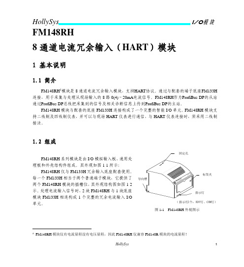
FM148RH 仅与 FM133H 冗余输入底座配套使用。 每一个 FM133H 相当于两个普通端子模块,它提供了 导向槽 两个 FM148RH 模块的插槽位,其外观结构图如图 1-2 示。处理电流输入信号时,2 块 FM148RH 与 1 块底座 模块 FM133H 相连构成 1 个完整的冗余电流输入 I/O 单元。
美睿达手持设备Hart模块接口连接线说明书

CHECKED ENG APPR.
TIM LINT STEVE WALKER
1-26-07 1-26-07
10920 MADISON AVENUE CLEVELAND, OHIO 44102
9. MACHINED SURFACE FLAT WITHIN .001 IN/IN [0.25mm/mm]; OTHER SURFACE FLAT WITHIN .005 IN/IN [0.127 mm/mm]
DO NOT USE DONGLE CONNECTOR
C
2
REV. ECO # IR EO - 6398 A EO - 6443
1
REVISIONS HISTORY DESCRIPTION
INITIAL RELEASE CORRECT ATEX STRING AND "IS" MARK
DATE BY 12-20-07 TL 2-13-08 TL
.001 / [0.025] MIN. 12. TOLERANCES DECIMALS ARE: INCH
X.X .030
X.XX .010
mm X.X 0.8 X.XX 0.25
ANGULAR 0 30'
COMMENTS: DOCUMENTED ON 3D CAD with SolidWorks.
● Do Not replace batteries in explosive or hazardous atmosphere.
● Do Not use any battery other than these listed.
(6) AA
Alkaline, Duracell PC1500 Alkaline, Duracell MN1500 Alkaline, Varta 4906
SIMATIC ET 200SP 6ES7134-6TD00-0CA1 6-线HART输入模块说明书

8 byte; + 1 byte for QI information 28 byte; + 1 byte for QI information
Analog inputs Number of analog inputs ● For current measurement permissible input current for current input (destruction limit), max. Input ranges (rated values), currents ● 0 to 20 mA ● -20 mA to +20 mA ● 4 mA to 20 mA ● Input resistance (4 mA to 20 mA) Cable length ● shielded, max.
No
● for current measurement as 2-wire transducer
Yes
Errors/accuracies Linearity error (relative to input range), (+/-) Temperature error (relative to input range), (+/-) Crosstalk between the inputs, min. Repeat accuracy in steady state at 25 °C (relative to input range), (+/-)
General information Firmware version ● FW update possible usable BaseUnits Color code for module-specific color identification plate Product function ● I&M data ● Measuring range scalable Engineering with ● STEP 7 TIA Portal configurable/integrated as of version ● STEP 7 configurable/integrated as of version ● PCS 7 configurable/integrated as of version ● PROFIBUS as of GSD version/GSD revision ● PROFINET as of GSD version/GSD revision Operating mode ● Oversampling ● MSI
MODBUS-HART转换模块
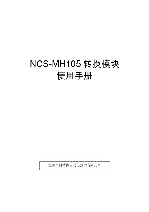
NCS-MH105转换模块使用手册沈阳中科博微自动化技术有限公司1 系统概述NCS-MH105转换模块是沈阳中科博微自动化技术有限公司新研发的一款Modbus-RTU协议与HART协议的转换设备。
NCS-MH105转换模块作为Modbus主机通过RS485接口与具有Modbus-RTU通讯功能的设备进行通讯,能够把设备中的数据转换成HART设备变量输出,并且支持4~20mA电流输出。
NCS-MH105转换模块,如下图1所示:图1NCS-MH105转换模块NCS-MH105转换模块作为HART设备可以与其他HART设备一样通过HART调制解调器与计算机组成HART系统,并通过HART上位机的组态软件配置NCS-MH105转换模块的各种参数。
如下图2所示:图2NCS-MH105转换模块系统连接图2 设备性能指标NCS-MH105转换模块具有强大的处理能力,具体硬件参数如下:NCS-MH105转换模块与Modbus设备之间通过标准Modbus-RTU协议进行通讯,NCS-MH105转换模块作为主站,Modbus设备作为从站,默认的通讯参数如下:NCS-MH105转换模块支持的Modbus功能码如下:3 结构与工作原理NCS-MH105转换模块支持4个动态变量,6个设备变量,MODBUS设备采集的数据通过MODBUS寄存器配置到NCS-MH105转换模块的设备变量上,再进过设备变量到动态变量的映射,作为设备的输出,并且设备支持4~20mA的模拟信号的输出。
NCS-MH105转换模块原理框图如0所示:图3NCS-MH105转换模块原理框图4 系统连接及使用4.1 设备安装及使用NCS-MH105转换模块尺寸为96×56mm,可以配合标准亚当模块外壳也可以通过定位孔安装到设备中,如图4所示。
图4NCS-MH105转换模块接线端子图NCS-MH105转换模块的接线如下表:NCS-MH105转换模块由HART总线供电,485通讯部分需要外部5V供电,通讯电缆推荐使用带屏蔽的双绞线,这样可以提高设备的抗电磁干扰能力。
HART-Adapter 数据手册说明书

HART-AdapterHART FSK / PC modem— USB—Ex(Haz.) and Non-Ex(Haz.) applicationsHART FSK / PC modem II— RS 232C—Non-Ex(Haz.) applications HART LCI / PC adapter — with small connectorHART-Adapter2 10/63-6.71-EN | HART-AdapterNHA121-NX, NHA121-NO HART FSK / PC-USB-ModemAdapterThe modem NHA121-NX / -NO is designed to provide a communication link between a desktop computer or PC notebook and the HART field device. The PC can be taken into the field and connected with the HART network within seconds thanks to the USB plug & play features. Mobile data acquisition as well as parameterisation are preferred operational areas.For the use in hazardous areas we deliver an intrinsic safe, ATEX certified version: NHA121-NX. It is functionally equivalent to the NHA121-NO type.Hardware ProfileThe USB modem supports the HART specification standard. Its connector cable comes with a twisted pair wire 2-pin terminal block to dual test clips. The modem can work as primary as well as secondary Master. The modem is available with opto-isolation to the HART network. The device is USB-bus powered, thus not depending on external power supplies. The communication does not interfere with the normal operation of the field device. The interface is housed in a compact shell that attaches securely to the USB port.SoftwareThe interface supports the Windows operation systems and it can work like a serial modem. It offers a serial COM-port so that already existing applications can be used without any changes.Further more a device type manager (DTM), incl. license key, is included. The DTM provides communication betweendevices on the HART bus and their DTMs. With its help set-up and configuration of the HART network can be done.Device Type Manager for HART Networks (optional)The software package HART FDT consists of the component: — CommunicationDTM CommDTM for NHA121-NX / -NOCommDTMThe CommDTM is compliant with the current FDT specification 1.2.1. It requires the NHA121-NX/-NO as basic hardware. The DTM takes care of its management and configuration. It replaces the vendor specific configuration software with a standard FDT approach.The CommDTM can be compared to a device driver which facilitates the communication between the field devices at the HART bus and their device DTMs. It therefore supports the commissioning of the field devices from one central workstation.The communication interface can be employed as primary as well as secondary master. The configuration window of the CommDTM enables the user to switch between the twooptions. The retry limit and the number of preambles may also be set through the configuration window.FeaturesThe function "Device List" allows the scan for devicesattached to the HART bus. All devices, which can be reached through a polling address, are listed. Additional information is available for every device found, including the tag, the vendor identification, the device type and the device ID.In order to change the poll address of a device, it can be selected from the device list. A new window opens which permits the setting of the new poll address. The CommDTM secures that the device is not currently in use by anyDeviceDTM. The device state is indicated in the device list. The CommDTM also checks whether the new poll address was already taken by another device, preventing an address overlay between different devicesExplosion protection for NHA121-NXApproved for connection to an intrinsically safe transmitter circuit.Technical dataModem-Typ NHA121-NX NHA121-NOM10678M10679PC-Interface USBOperational Area mobile / stationaryModem Chip HT2012Connector 2-pin test clipsTransmission Rate 1200 Bit/s (600 Bit/s optional)DTM HART Version 5 or higherOperating system Windows 7, Windows Vista, Windows XP und Windows 2000 (32-bit versions only)ATEXCE Certification CE,ATEX II (2) G [Ex ia] IIC -Delivery Contents Hardware with fix USB cable and pluggable test clips, Driver and Configuration Software,CommDTM, DTM License key, Documentation on CDHART-Adapter | 10/63-6.71-EN 3HART-Adapter4 10/63-6.71-EN | HART-AdapterNHA102-NOTechnical dataElectrical data Voltage U ss 0,6 V, average-free Current < 3 mA Power max 1,5 mW Frequency 1,2 and 2,2 kHz Electromagnetic compatibility (EMC)to IEC 801 / NAMUR— HART-FSK-Modem II— Digital communication through FSK (standard HART Protocol)— Communication by tapping at the analog 4 ... 20 mA signal transmission— Potential separation between the PC and the device — Average-free signal transmission, hence unaffected 4 ... 20 mA output signalEnvironmental capabilities Operating temperature 0 ... 45 °C Storage temperature -20 ... 55 °C Air humidity< 80 %— Digital signals, “0“ = 2.2 kHz; “1“ = 1.2 kHzApplicationsThe FSK modem acts as a sort of digital communication“translator“ between the computer and the transmitter. Power supply is realized automatically via the serial RS 232Cinterface of the computer, in parallel with data transmission.HousingMaterial Plastic Degree of protection IP 20Connectors9-pin or 25-pin Sub-D socket (PC side), screw terminals and 0.75 m cables with clip-on connectors (device side)Dimensions 55 mm x 55 mm x 17 mm Weightapprox. 0,1 kgCommunication is done by tapping at any point of the analog 4 ... 20 mA signal transmission. No special attention has to be paid to polarity for the 2-pole tap. The devices are HART-compatible, i. e. they have a certain internal resistance, which must be considered. Power for data tapping is supplied in parallel from the PC via the RS 232 C interface.The modem has a 9-pin or 25-pin Sub-D socket on the PC side and is connected to the transmitter via 0.75 m cables with clip-on connectors on the device side. The cables connect to the modem through screw terminals.M10680Fig. 1M10681Fig. 2:Connection diagram, with 250 Ω communication resistor1 Internal resistance for supply unit > 250 Ω(resistance can also be realized as external communication resistor) 2 Internal resistance for signal source >10 kΩFig. 3:Connection diagram, without 250 Ω communication resistor2 Internal resistance for signal source >10 kΩHART-Adapter | 10/63-6.71-EN 5HART-Adapter6 10/63-6.71-EN | HART-AdapterNHA201-NOM10683LCI adapterIn offline mode (e. g. in the shop or lab) the local communication interface (LCI) can be used forparameterization. In this case the transmitter is powered via the PC. In online mode local communication is possible without affecting the analog output.The LCI adapter is used to connect the transmitter to the PC.Universal through:— 9-pin or 25-pin SUB D connectorFig. 4with small connector for:— Positioner, TEU421, TEU471, BCI100 (Contrans I), Power Transducer SU.Ordering informationHART-FSK / PC-adapter Catalog No.1)3KDE636710L0001NHA121-NX (14290-0203) (Note USB / HART FSK Modem,IS input II (2) G [Ex ia] IIC, electrical isolation,for Windows 7, Windows Vista, Windows XP and Windows 2000 (32-bit versions),to connect a tool to HART devices via a PC / Notebookincl. standard driver and Common DTM (FDT 1.2.1), DTM license key,USB cable, connection cable with clips and manual (*.pdf)NHA121-NO (14290-0105) (Note1)3KDE636710L0002USB / HART FSK Modem,Electrical isolation,for Windows 7, Windows Vista, Windows XP and Windows 2000 (32-bit versions),to connect a tool to HART devices via a PC / Notebookincl. standard driver and Common DTM (FDT 1.2.1), DTM license key,USB cable, connection cable with clips and manual (*.pdf)NHA102-NO (Note 1)7957838 RS 232C / HART FSK Modem II,connector version, with connection clipsHART-LCI / PC-adapter BestellnummerNHA201-NO319621 RS 232C / LCI-Adapter with small connector,for positioners, TEU421, TEU471, BCI100 (Contrans I modules),Power Transducer SUNote 1: for configuration of general HART-instruments and TH(x)01, TS(x)02, BCI100 (Contrans I) backplaneHART-Adapter | 10/63-6.71-EN 7Contact us10/63-6.71-E N R e v . K 05.2011NoteWe reserve the right to make technical changes or modify the contents of this document without prior notice. With regard to purchase orders, the agreed particulars shall prevail. ABB does not accept any responsibility whatsoever for potential errors or possible lack of information in this document.We reserve all rights in this document and in the subject matter and illustrations contained therein. Any reproduction, disclosure to third parties or utilization of its contents - in whole or in parts – is forbidden without prior written consent of ABB.Copyright© 2011 ABB All rights reserved3KXN671000R1001ABB Automation Products GmbH Service Instrumentation Kallstadter Straße 168309 Mannheim, GermanyCustomer Service Center: +49 180 5 222 580* E-Mail:*************************.com*14 cents/minute from German landlines, max. 42 cents/minute from mobiles.® Windows and Windows Vista are trademarks ofMicrosoft Corporation.® HART is a trademark of HART CommunicationFoundation.。
西门子 ET 200SP HA HART 应用指南说明书

/CN/view/zh/109762437C o p y r i g h t S i e m e n s A G C o p y r i g h t y e a r A l l r i g h t s r e s e r v e d目录1 HART 功能概述 ............................................................................................ 3 2硬件组态及基本设置...................................................................................... 4 2.1 硬件组态及设置 .............................................................................. 4 2.2 通过通道驱动块读取通道模拟量信号 ................................................ 8 2.3 8 HART 设置下的HART 变量 .......................................................... 9 2.4 1 multiHART 或4 multiHART 设置下的HART 变量.......................... 10 2.4.1 1 multiHART................................................................................. 10 2.4.2 4 multiHART (12)3通过读取数据记录访问HART 变量............................................................... 14 3.1 命令3读取HART 变量.................................................................. 14 3.2 命令121读取HART 变量 .. (18)C o p y r i g h t S i e m e n s A G C o p y r i g h t y e a r A l l r i g h t s r e s e r v e d1 HART 功能概述HART 通信是在4-20mA 信号上叠加一个幅值为±0.5mA 的正弦波信号,通过调整正弦波的频率来表示信号0和1,如图1-1所示,1200Hz 表示1,2200Hz 表示0。
SS4-A HART模块用户指南说明书

Manuale utente SS4-A HARTStorico delle revisioniAutore Revisione Data CommentiT. Lapp A 19 aprile 2013 Edizione inizialeIndice1Introduzione (4)24-20 mA di SS4 (4)3Comandi HART supportati (5)3.1 Comando 0 (5)3.2 Comando 1 (6)3.3 Comando 2 (6)3.4 Comando 3 (7)3.5 Comando 6 (8)3.6 Comando 7 (9)3.7 Comando 8 (9)3.8 Comando 12 (9)3.9 Comando 13 (10)3.10 Comando 14 (10)3.11 Comando 15 (11)3.12 Comando 16 (11)3.13 Comando 20 (12)3.14 Comando 50 (12)4Indicazioni LED (13)5Indirizzo modulo HART (13)6Montaggio modulo HART (13)7Collegamenti modulo HART (14)1 IntroduzioneIl modulo Fire Sentry FSCHCOM-Array SS4 è un dispositivo ausiliario checonsente ai rilevatori di fiamma dellaserie SS4 di comunicare con unmaster di rete HART. Il moduloHART può essere considerato unconvertitore di protocollo. Il rilevatoredi fiamma comunica con i dispositiviesterni mediante il protocolloproprietario FireBus-I. Questomodulo HART ottiene lo stato diallarme e di guasto utilizzandoFireBus-I, quindi alla ricezione di uncomando HART risponde al masterHART restituendo le informazioni necessarie. La comunicazione con il master richiede che la richiesta corrisponda all'indirizzo breve (assegnato dal selettore a ghiera) o all'indirizzo lungo (una combinazione di tipo di dispositivo e numero di serie).Per la comunicazione HART vengono utilizzati il pin n. 2 e il pin n. 3 di J102 delmodulo. Il circuito di corrente di 4-20 mA ha origine dal pin n. 2 quando gliinterruttori su S100 sono attivati; la terra è il punto di ritorno della corrente. Per i dettagli di collegamento vedere più avanti.2 4-20 mA di SS4Questo FSCHCOM-SS4 fornisce un valore analogico di 4-20 mA e protocollo HART simultaneamente. Nella configurazione single drop (I = un master verso un dispositivo) la corrente analogica di 4-20 mA fornisce le informazioni indicate di seguito.0 mA : Guasto PCB, guasto tensione, guasto temperatura, guasto relè.2 mA : Test automatico ottico non riuscito e guasto coperchio assente.4 mA : Normale.20 mA : Allarme.3 Comandi HART supportatiIl modulo SS4-A HART supporta i comandi elencati di seguito.3.1 Comando 0Utilizzare il comando 0 per leggere l'identificatore unico.Risposta al comando 0:ID produttore: 6042 esadecimale stringa FSCHCOMID prodotto: E180 esadecimaleL'indirizzo di interrogazione è assegnato dal selettore a ghiera RSW100 (0, 1, 2, 3, 4, 5, 6, 7, 8, 9, A, B, C, D, E, F).Posizionando RSW100 nella posizione 1, 2, 3 fino a F, si mettono i dispositivi in modalità indirizzo hardware. L'indirizzo hardware esclude l'indirizzo software.Posizionando RSW100 nella posizione 0, si mettono i dispositivi in modalità di indirizzamento software.È possibile utilizzare il comando 6 per scrivere l'indirizzo di interrogazione nel modulo FSCHCOM. Quando l'indirizzo di interrogazione software è scritto nel modulo FSCHCOM, l'indirizzo viene salvato nella memoria flash fino a quando viene sovrascritto dal comando 6 successivo.Byte Formato Descrizione0 8 senzasegnoDeve essere 254 decimale (FE esadecimale)Da 1 a 2 Codice Tipo di dispositivo E1 80 esadecimale3 8 senzasegnoNumero minimo di byte di preambolo dal master = 54 8 senzasegnoRevisione principale HART = 75 8 senzasegnoLivello revisione dispositivo = 06 8 senzasegnoRevisione software = 17 8 senzasegno Bit 7, 6, 5, 4, 3 revisione hardware = 0x10 Bit 2, 1, 0 codice segnale fisico 0x018 8 senzasegnoFlag = 0. N/DDa 9 a 11 24 senzasegnoID unico dispositivo dal produttore12 8 senzasegnoNumero minimo di byte di preambolo al master = 513 8 senzasegnoNumero massimo di variabili dispositivo = 4Da 14 a 15 16 senzasegno Contatore cambio configurazione = 0. Nessuna configurazione utente16 8 senzasegnoStato del dispositivoDa 17 a 18 16 senzasegnoCodice ID produttore = 60 42 esadecimale3.2 Comando 1Utilizzare il comando 1 per leggere la variabile primaria.Risposta al comando 1:Allarme e stato dispositivo sono salvati nella variabile primaria (unità di misura in mA), dove:.Byte Formato Descrizione0 Codice Codice unità in mADa 1 a 4 Virgolamobile 0 mA : Guasto PCB, guasto tensione, guasto temperatura, guasto relè.2 mA : Test automatico ottico non riuscito e guasto coperchio assente.4 mA : Normale.20 mA : Allarme3.3 Comando 2Utilizzare il comando 2 per leggere la corrente di circuito (ignorare l'intervallo percentuale).Risposta al comando 2:La corrente di circuito corrisponde sempre alla corrente che può essere misurata da un milliamperometro in serie con il dispositivo. È compresa la corrente dicircuito in condizioni di allarme. I sensori di fiamma SS4 non dispongono di un valore percentuale, quindi ignorare l'uscita percentuale della risposta.Byte Formato DescrizioneDa 0 a 3 Virgolamobile Corrente di circuito in milliampere0 mA : Guasto PCB, guasto tensione, guasto temperatura, guasto relè.2 mA : Test automatico ottico non riuscito e guasto coperchio assente.4 mA : Normale.20 mA : AllarmeDa 4 a 7 Virgolamobile Lettura %.0 mA = 0%2 mA = 10%4 mA = 20% 20 mA = 100%3.4 Comando 3Utilizzare il comando 3 per leggere la variabile dinamica e la corrente di circuito. Risposta al comando 3:Byte Formato DescrizioneDa 0 a 3 Virgolamobile Corrente di circuito variabile primaria (unità in milliampere)0 mA : Guasto PCB, guasto tensione, guasto temperatura, guasto relè.2 mA : Test automatico ottico non riuscito e guasto coperchio assente.4 mA : Normale.20 mA : Allarme4 Codice Codice unità per mA. Variabile 1Da 5 a 8 Virgolamobile Variabile 1. Guasto tensione4 Ma : Normale20 ma : guasto tensione (troppo bassa o troppo alta)9 Codice Codice unità per mA. Variabile 2Da 10 a 13 Virgolamobile Variabile 2. Guasto temperatura 4 mA : Normale20 mA : Temperatura eccessiva.14 Codice Codice unità per mA. Variabile 3Da 15 a 18 Virgolamobile Variabile 3. Test automatico e coperchio rimosso4 mA : Normale20 mA : Test automatico non riuscito (lente sporca) e/o coperchio rimosso.19 Codice Codice unità per mA. Variabile 4Da 20 a 23 Virgolamobile Variabile 4. Comunicazione tra modulo FSCHCOM e rilevatore di fiamma SS4.4 mA : Normale.20 mA : Temperatura eccessiva.3.5 Comando 6Utilizzare il comando 6 per scrivere l'indirizzo di interrogazione e la modalità di corrente di circuito nel dispositivo di campo.Ogni dispositivo HART deve disporre di un indirizzo di interrogazione.Risposta al comando 6:Byte Formato Descrizione0 8 senzasegnoIndirizzo di interrogazione1 Codice 0 = corrente di circuito disattivata, 1 corrente di circuitoattivata.La corrente di circuito di questo modulo FSCHCOM vieneabilitata/disabilitata dagli interruttori DIP hardware S1.Indipendentemente dalla posizione di S1 questo byte èsempre 0. Verificare di avere impostato S1 diconseguenza.Quando il comando 6 viene ricevuto dal modulo SS4HCOM, l'indirizzo diinterrogazione assegnato (da 0 a 15 decimale, da 0 a 0x0f esadecimale), ilmodulo SS4HCOM salva l'indirizzo breve assegnato nella memoria flash eutilizza l'indirizzo breve assegnato fino allo spegnimento.All'accensione il modulo SS4HCOM legge in primo luogo il selettore a ghiera RSW1. Se RSW1 è in posizione 0, il modulo SS4HCOM rilegge l'indirizzo breve salvato. Se RSW1 è in posizione diversa da 0 (cioè 1, 2, 3, 4, 5…A, B, C, D, E,F), il numero di posizione viene utilizzato come indirizzo breve.Utilizzare il comando 7 per leggere l'indirizzo di interrogazione e la modalità di corrente di circuito.Risposta al comando 7:Byte Formato Descrizione0 8 senzaIndirizzo di interrogazionesegno1 Codice 0 = corrente di circuito disattivata, 1 corrente di circuitoattivata.La corrente di circuito di questo modulo FSCHCOM vieneabilitata/disabilitata dagli interruttori DIP hardware S1.Indipendentemente dalla posizione di S1 questo byte èsempre 0. Verificare di avere impostato S1 diconseguenza.3.7 Comando 8Utilizzare il comando 8 per leggere la classificazione di variabile dinamica.Questo comando non si applica ai sensori di fiamma, tuttavia il moduloFSCHCOM risponde come indicato di seguito:Risposta al comando 8:Byte Formato Descrizione0 Codice 0 per codice indefinito1 Codice 0 per codice indefinito2 Codice 0 per codice indefinito3 Codice 0 per codice indefinito3.8 Comando 12Utilizzare il comando 12 per leggere il messaggio contenuto nel moduloFSCHCOM.Risposta al comando 12:Byte Formato DescrizioneMessaggio alfanumericoDa 0 a 23 ASCII inpacchettiUtilizzare il comando 13 per leggere Etichetta, Descrittore, Data di rilascio.Risposta al comando 13:Byte Formato DescrizioneEtichettaDa 0 a 5 Stringa inpacchettiDescrizioneDa 6 a 15 Stringa inpacchetti18-20 Data Data del rilascio del firmware3.10 Comando 14Utilizzare il comando 14 per informazioni sulla variabile primaria del trasduttore. Risposta al comando 14:Byte Formato DescrizioneDa 0 a 2 24 senzaNumero di serie del trasduttoresegno3 Codice 0 per indefinito 39 (27 esadecimale) per milliampereIl limite superiore è 20 mA (41 A0 00 00) esadecimale Da 4 a 7 VirgolamobileDa 8 a 11 VirgolaIl limite inferiore è 0 mA (00 00 00 00) esadecimale mobileDa 12 a 15 VirgolaIl limite inferiore SPAN è (00 00 00 00) esadecimale mobileQuesto comando non è applicabile ai sensori di fiamma. Tuttavia il modulo FSCHCOM risponde al comando con tutti zeri.Risposta al comando 15:Byte Formato Descrizione0 Codice Codice 0 = Alta priorità1 Codice Codice 0 = Indefinito2 Codice Codice 0 = IndefinitoDa 3 a 6 VirgolaValore intervallo superiore 20 mAmobileValore intervallo inferiore 0 mADa 7 a 10 VirgolamobileFattore di smorzamento 0 = Non applicabileDa 11 a 14 Virgolamobile15 Codice Codice 0 = Indefinito16 Codice Codice 0 = Indefinito17 codice Codice 0 = Indefinito3.12 Comando 16Utilizzare questo comando per leggere il numero di assemblaggio finale.Questo comando non è applicabile ai sensori di fiamma. Tuttavia il modulo FSCHCOM risponde al comando con tutti zeri.Risposta al comando 16:Byte Formato DescrizioneDa 0 a 2 24 senza00 00 00 = Non applicabilesegnoUtilizzare questo comando per leggere l'etichetta lunga.Risposta al comando 20:Byte Formato DescrizioneDa 0 a 31 stringa Etichetta lunga = "FSHCOM MODULE SS4".3.14 Comando 50Questo comando non è applicabile ai sensori di fiamma. Tuttavia il modulo FSCHCOM risponde al comando con tutti zeri.Risposta al comando 50:Byte Formato DescrizioneCodice 0 = Indefinito0 8 senzasegno1 8 senzaCodice 0 = Indefinitosegno2 8 senzaCodice 0 = Indefinitosegno3 8 senzaCodice 0 = Indefinitosegno4 Indicazioni LEDSul modulo HART sono presenti quattro LED per le indicazioni di stato, comeindicato di seguito:Il LED giallo D105 indica guasto o normale. Giallo acceso = guasto, spento = normale.LED verde D102. Verde fisso = Hart interrogato e risponde.Spento = non attivo.LED verde D103. Verde lampeggiante = andamento della comunicazione SS4.Verde fisso o spento = in attesa di risposta da SS4.LED rosso D104. Rosso fisso = allarme Spento = nessun allarme.5 Indirizzo modulo HARTL'indirizzo di interrogazione è assegnato dal selettore a ghiera RSW1(0, 1, 2, 3, 4, 5, 6, 7, 8, 9, A, B, C, D, E, F).Posizionando RSW1 nella posizione 1, 2, 3 fino a F, si mettono i dispositivi inmodalità indirizzo hardware. L'indirizzo hardware esclude l'indirizzo software.Posizionando RSW1 nella posizione 0, si mettono i dispositivi in modalità diindirizzamento software. È possibile utilizzare il comando 6 per scrivere l'indirizzo di interrogazione nel modulo FSCHCOM. Quando l'indirizzo di interrogazionesoftware è scritto nel modulo FSCHCOM, l'indirizzo viene salvato nella memoriaflash fino a quando viene sovrascritto dal comando successivo.6 Montaggio modulo HARTSe è stata ordinata l'opzione modulo Hart insieme al modulo SS4, moltoprobabilmente il modulo HART è già installato sul modulo SS4.Se il modulo HART è stato ordinato separatamente, ricordarsi di fissare il modulo HART sul modulo SS4 mediante due viti.7 Collegamenti modulo HARTPer collegare un singolo modulo HART a un master HART, attenersi allaprocedura di seguito.1. Spegnere l'alimentazione del rilevatore.2. Collegare la linea di segnalazione HART ai pin n. 2 e 3 di J102.3. Se è necessaria segnalazione di sorgente di corrente oltre a HART, attivareentrambi gli interruttori S100 premendoli (verso la scheda elettronica).4. Collegare il terminale positivo del carico di corrente al pin n. 2 di J102 (il pinaccanto al pin di terra).5. Collegare il terminale di ritorno del circuito di corrente al pin n. 1 di J102 (il pindi terra). Verificare che la resistenza di circuito nominale sia di circa 250 ohm.6. Accendere l'alimentazione a 24 Vcc per il rilevatore.Nel caso sia necessario configurare una rete HART multi-drop, contattarel'azienda per ulteriori indicazioni. Recapiti di Honeywell Analytics: Europa, Medio Oriente, Africa, India Life Safety Distribution AG Javastrasse 28604 HegnauSvizzeraTel: +41 (0)44 943 4300Fax: +41 (0)44 943 439Tel. India: +91 124 4752700 **************************AmericheHoneywell Analytics Inc.405 Barclay Blvd.Lincolnshire, IL 60069USATel.: +1 847 955 8200Numero verde: +1 800 538 0363 Fax: +1 847 955 8210***********************Asia PacificoHoneywell Analytics Asia Pacific #701, Kolon Science Valley (I) 43 Digital-Ro 34-Gil Guro-Gu Seul, 152-729CoreaTel.: +82 (0)2 6909 0300Fax: +82 (0)2 2025 0328**************************Assistenza tecnicaEMEAI: ********************** USA: ***************************AP: ***************************Nota: Abbiamo fatto del nostro meglio per garantire l'assoluta precisione della documentazione fornita. Tuttavia, Honeywell Analytics non si assume alcuna responsabilità per eventuali errori od omissioni. Poiché dati e leggi sono soggetti a variazioni raccomandiamo a tutti i nostri clienti di richiedere copie aggiornate di regolamenti, norme e linee guida. Questa pubblicazione non riveste carattere contrattuale. Edizione A_04/2013 H_MAN0961_6352-001_IT 3228。
AI711-H 说明书
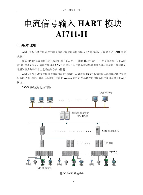
电流信号输入HART模块AI711-H1基本说明AI711-H为ECS-700系统中的8通道点隔离电流信号输入HART模块,可连接8块HART智能仪表。
符合HART协议的信号进入模块后被分为两路:一路是HART信号,一路是电流信号。
HART 信号经模块处理后,通过控制器和SAMS通信服务器传送给SAMS数据服务器。
电流信号经模块处理后转换为数字信号上送给控制器参与控制。
AI711-H与SAMS软件结合构成设备管理系统,可对符合HART协议的现场总线的智能仪表进行数据采集、组态、网络设备管理,允许Rosemount的275型手持操作器作为第二主设备接入HART 网络。
SAMS系统的结构如下图:图 1-1 SAMS系统结构SAMS软件的详细设置和具体使用方法见《SAMS软件使用手册》。
AI711-H每个通道使用4个端子实现电流配电/不配电的选择,无需跳线选择。
同时AI711-H提供可选择的配电功能。
为了获得更高的精度和具备快速采样能力,AI711-H利用了过采样和数字滤波技术,对信号噪声和供电噪声有更好的抑制能力。
在抗工频干扰的配置情况下也可以达到8通道250ms的采样更新速率;而在快速采样的配置情况下更可以达到8通道50ms的采样更新速率。
模块前面板上的指示灯为模块状态、网络状态、供电状态等提供了直接的指示信息。
2使用说明2.1LED指示灯说明2.2AI接口特性对于需要配电的场合,AI711-H模块可以提供通道间隔离的配电电源,用于驱动现场变送器。
AI711-H模块接口电路如下图所示:图 2-1 AI711-H模块接口电路AI711-H的每个通道占据4个接线端子,对不同类型的信号其接线方式也有所不同。
1)配电电流信号若现场侧是需要模块提供配电电源的电流信号输出设备,则接线电路如下图所示(箭头所示为电流方向):图 2-2 配电电流信号接线图2)不配电电流信号若现场侧是不需要模块提供配电电源的电流信号输出设备,则接线电路如下图所示(箭头所示为电流方向):图 2-3 电流信号接线图2.3端子接线说明AI711-H模块一个通道分配4个接线端子,实现两种信号的接入。
- 1、下载文档前请自行甄别文档内容的完整性,平台不提供额外的编辑、内容补充、找答案等附加服务。
- 2、"仅部分预览"的文档,不可在线预览部分如存在完整性等问题,可反馈申请退款(可完整预览的文档不适用该条件!)。
- 3、如文档侵犯您的权益,请联系客服反馈,我们会尽快为您处理(人工客服工作时间:9:00-18:30)。
LTHR2110-10V-2RN HART 通信模块 1
北京力天宏威科技 有限公司 Beijing LTHonway Technology Co.,Ltd
●满足本质安全要求,符合 RoHS 标准。 ●储存温度:-40℃~70℃。 ●相对湿度: 90%(无凝结)。
1.2 模块方框图
LTHR2110 用户手册 LTHR2110 User Manual
图 1.1 模块方框图 简单的电路就可以实现 HART 通信,同时该 HART 模块也可以通过 UART 口读取外部的数据转换成 HART 信号耦合到电流环路上。该接口可以定制为 RS232,RS485 接口。
1.3 HART 评估模块
图 1.2 HART 评估模块
HART 评估板包括以下几部分:
功能部件:
北京力天宏威科技有限公司自行研发生产的 HART 模块 LTHR2110-10V-2RN 集成了新塘 MCU,安森 美的 A5191 和 ADI AD421 芯片,实现了高性能低功 耗并且稳定的现场通讯。
LTHR2110-10V-2RN 的设计缩减了元件数量及功 率消耗,同时缩短了产品设计周期,加速上市时间, 为客户节省下了大量的成 本。并可直接应 用于与现 场设备通信,转换成 HART 通信信号完成与 HART 主 机通信。
深圳分公司
FAE 邮箱:peter.peng@ 彭飞 销售电话:0755-8376 4792/3219/7518/8954/4775/9209 0755-83975390 传真:0755-83763347/83290087 地址:深圳市龙岗区布吉镇坂田吉华路 393 号英达丰科技园 3 楼
修订历史
版本 V1.0.0
日期 2012-3-16
LTHR2110 用户手册 LTHR2110 User Manual
原因 创建文档
LTHR2110-10V-2RN HART 通信模块 ii
北京力天宏威科技 有限公司 Beijing LTHonway Technology Co.,Ltd
北京总公司
3. 电气规范.......................................................................................................................................... 5 4. HART 模块尺寸................................................................................................................................. 6
据参数。
V1.0.0
2012-3-20
北京力天宏威科技 有限公司 Beijing LTHonway Technology Co.,Ltd
LTHR2110-10V-2RN 数据手册
LTHR2110 用户手册 LTHR2110 User Manual
概述
HART 协议是美国 Rosement 公司于 1985 年推 出的一种用于现场智能仪 表和控制室设备 之间双向 通信的协议规程。具有低功耗,低速率,高可靠性, 传输距离远等特点,广泛应用各种工业现场。
北京力天宏威科技有限公司产品数据手册
LTHR2110-10V-2RN HART 通信模块
LTHR2110-10V-2RN 数据手册
类别 关键词
摘要
版本 创建日期
内容 HART 评估模块
本文主要介绍北京力天宏威自行研发的 HART 评估模块,对硬 件使用性能及参数做详细的介绍,方便用户了解该评估模块数
销售与服务网络
FAE 邮箱:allan.jin@ 金彦哲
销售电话:010-82637265/7289/7279/7269/7261 010-82637272/7276/7288/7909/8791/7293
传真:010-82639385/8368 地址:北京市海淀区彩和坊路 10 号 1+1 大厦 503 室
网址:/
LTHR2110 用户手册 LTHR2110 User Manual
上海分公司
FAE 邮箱: lee.zhang@ 张义宾 销售电话:021-51113181/3086/3633/3396/3586/3323 传真:021-51113220 地址:上海市长宁区中山西路 933 号虹桥银城 2004-2006 室
LTHR2110-10V-2RN 的设计缩减了元件数量及功率消耗,同时缩短了产品设计周期,加速上市时间,为 客户节省下了大量的成本。并可直接应用于与现场设备通信,转换成 HART 通信信号完成与 HART 主机通信。
1.1 特性
●通讯接口属纯硬件转换,没有时延,效率高。 ●MCU:新塘 ARM Cortex™-M0 内核的 32 位微控制器。 ●Bell202 标准的 FSK 频移键控信号,载波为 1200Hz 和 2200Hz。 ●HART 与现场设备通信接口可定制。 ●半双工通信(1200,ODD,8,1)。 ●接口类型:SPI( 主从)、UART(2 路)。 ●传输距离:单芯带屏蔽双绞线电缆可达到 3000m,多芯带屏蔽双绞线电缆长度可达到 1500 m。 ●功耗:DC10-35V,<10mA。 ●供电电压:8~40VDC,工作电流<4mA,推荐 24VDC。 ●HART 接口:内阻 240Ω ,电流 4~20mA。 ●工作温度:-40℃~85℃。
产品特性
●通讯接口属纯硬件转换,没有时延,效率高。 ●MCU:新塘 ARM Cortex™-M0 内核的 32 位微控制器。 ●Bell202 标准的 FSK 频移键控信号,载波为 1200Hz 和 2200Hz。 ●HART 与现场设备通信接口可定制。 ●半双工通信(1200,ODD,8,1)。 ●接口类型:SPI( 主从)、UART(2 路)。 ●功耗:DC10-35V,<10mA。 ●供电电压:8~40VDC,工作电流<4mA,推荐 24VDC。 ●HART 接口:内阻 240Ω ,电流 4~20mA。 ●工作温度:-40℃~85℃。 ●满足本质安全要求,符合 RoHS 标准。 ●储存温度:-40℃~70℃。 ●相对湿度: 90%(无凝结)。
远程监控 智能仪表 工业控制 设备制造 冶金工业 电力交通 楼宇自控 邮政通讯 科研机械 电力交通 装备自动化
应用领域
典型应用
LTHR2110-10V-2RN HART 通信模块 i
北京力天宏威科技 有限公司 Beijing LTHonway Technology Co.,Ltd
北 京 力 天 宏 威 科 技 有 限 公 司 自 行 研 发 生 产 的 HART 模 块 LTHR2110-10V-2RN 集成了新塘 MCU,安森美的 A5191 和 ADI AD421 芯片,实现了高性能低功耗并且稳定的现场通讯。
新塘 ARM Cortex™-M0 内核的 32 位微控制器 M054LAN 的高性能保证了 HART 通信的稳定高效。丰富的外 设接口也为该 HART 模块的高扩展性和高定制性奠定了基础。HART 芯片采用 A5191,它是专为实现 HART 协 议而设计的 CMOS 单芯片调制解调器,用于支持 HART 协议的现场仪表和控制器中。芯片只需外加少量无 源元件,即可满足 HART 物理层规范功能要求,包括调制与解调,输入信号滤波,载波检测和发送信号波 形整形等。AD421 是一款完整的环路供电型 4 mA-20mA 数字转换器,专为满足工业控制领域智能发射器制 造商的需求而设计。作为一种完全集成的高精度、低成本解决方案,该器件采用紧凑型 16 引脚封装,是以 极低成本提高 4 mA-20 mA 智能发射器分辨率的理想之选。
描述
供电及电流环接口: 评估板需要外部提供 DC5V 电压给 MCU 和 A5191 芯片供电
UART 通信接口:
电流环路需要 DC12V-36V 电压供电,同时电流环路给 AD421 供电 注意:DC5V 和环路电压不能共地 与外部经行数据交互,输出 TTL 电平
2. 系统级功能...................................................................................................................................... 3 2.1 工作原理................................................................................................................................... 3 2.2 通讯接口................................................................................................................................... 3 2.3 软件工具................................................................................................................................... 3
LTHR2110-10V-2RN HART 通信模块 iii
北京力天宏威科技 有限公司 Beijing LTHonway Technology Co.,Ltd
LTHR2110 用户手册 LTHR2110 User Manual
目录
1. 简介................................................................................................................................................. 1 1.1 特性 .......................................................................................................................................... 1 1.2 模块方框图 ............................................................................................................................... 2 1.3 HART 评估模块.......................................................................................................................... 2 1.4 主要功能介绍............................................................................................................................ 2