(完整word版)3GPP协议中文版-001
3GPP协议—24801-810 (译文)SAE
3GPP TR 24.801-810第三代合作伙伴项目核心网与终端技术规范组3GPP系统体系架构演进CT WG1方面(版本8)1、工作范围本文件讨论并介绍了3GPP系统架构演进(SAE)的CT1方面,为了使系统具有更高的数据速率,更低的时延,成为能支持多接入技术的最优分组系统。
确切的说,CT1方面包括通过用户设备(UE)处于空闲模式时进行非接入层(NAS)的功能。
NAS信令经由E-UTRAN在UE和演进分组核心网络(EPC)中进行处理,并且在UE与EPC之间的三层信令由非3GPP接入网络进行处理。
本文件还考虑在UE和核心网络之间的由像MBMS这样的特殊服务的要求而产生的非接入层的需求以及包括E-UTRAN内或在E-UTRAN和其他3GPP或非3GPP接入网络之间的安全性,QoS和移动性管理等问题。
本文件旨在介绍CT1 系统体系架构演进的相关材料,直到其稳定到足以移到适当的3P 技术规范。
2、参考文献3、定义和缩写3.1 定义聚合最大比特率:最大比特率限制的一组UE的非GBR承载的总比特率。
从3GPP TS23.401衍生定义[2]。
标签(仅E-UTRAN)表示如果E-UTRAN作为当前的无线接入网络,使用标签。
EMM上下文:当用户与MME之间成功建立连接时建立一个EMM上下文。
EMM连接模式:当用户与网络之间的NAS信令连接建立时UE就处于一个连接模式中。
本文档中使用的连接模式和3GPP TS 23.401中所述的一样。
EMM-空闲模式:当用户与网络之间没有NAS信令连接时用户处于空闲模式。
本文档中使用的连接模式和3GPP TS 23.401中所述的一样。
EPC演进分组核心网:是3GPP版本7中分组交换核心网的继承,在3GPP系统体系架构的演进。
演进分组系统:演进分组系统或演进3GPP分组交换域包括演进的分组核心网和演进的通用陆地无线接入网。
这个定义引用3GPP TS 23.401协议中的定义。
3gpp协议

3GPP协议1. 引言3GPP(第三代合作伙伴计划)是一个跨国合作组织,致力于制定和发展无线通信标准和技术。
3GPP协议是由该组织制定的一系列标准和规范,用于支持全球范围内的移动通信网络。
本文档将介绍一些常见的3GPP协议,包括LTE和5G等。
2. LTE协议LTE(Long-Term Evolution)是一种4G移动通信技术,它是3GPP协议中的一部分。
LTE协议定义了整个网络架构和通信协议层,包括物理层、数据链路层、网络层和应用层等。
•物理层:LTE物理层定义了信道、调制解调、传输和编码等。
它使用了OFDM(正交频分多路复用)和MIMO(多输入多输出)等技术,以提供高速数据传输和更好的信号质量。
•数据链路层:LTE数据链路层负责广播和多址接入,以及无线资源的调度和管理。
它使用了一种称为LTE无线接入接口的协议,用于无线资源的分配和调度。
•网络层:LTE网络层包括用户面和控制面,它负责用户数据的路由和传输,以及控制消息的传递。
LTE网络层使用IP协议进行数据传输,并提供QoS(服务质量)管理、移动性管理和安全性等功能。
•应用层:LTE应用层提供基于IP的应用服务,如VoIP(语音通信)、视频流媒体和互联网访问等。
3. 5G协议5G是下一代移动通信技术,也是3GPP协议的一部分。
5G协议在LTE的基础上进行了扩展和改进,以提供更高的数据传输速度、更低的延迟和更好的网络容量。
•物理层:5G物理层采用了新的技术,如更高的频率、更宽的频带和更高的MIMO级别等。
它可以支持更高的数据传输速率和更低的延迟。
•数据链路层:5G数据链路层引入了新的帧结构和调度算法,以提高网络的容量和效率。
它还支持更复杂的调度和编码技术,以适应不同的应用需求。
•网络层:5G网络层引入了网络切片(Network Slicing)的概念,以支持不同种类的应用和服务。
它还支持更灵活的移动性管理和安全性机制。
•应用层:5G应用层将继续提供基于IP的应用服务,并支持更高质量的多媒体传输和更低的延迟。
3GPP技术标准中文版

3GPP TS 25.401 V3.10.0 (2002-06) 翻译小组成员翻译的部分姓名俱乐部ID 电子邮件3GPP TS 25.401 V3.10.0 (2002-06) 5-9 孙扬 phaeton yang_sun_80@3GPP TS 25.401 V3.10.0 (2002-06) 9-11 赵建青 happyqq zjqqcc@3GPP TS 25.401 V3.10.0 (2002-06) 11-14 周翔babytunny babytunny@3GPP TS 25.401 V3.10.0 (2002-06) 15-18 马进xma 2003xm@3GPP TS 25.401 V3.10.0 (2002-06) 15-18 bluesnowing bluesnowing@3GPP TS 25.401 V3.10.0 (2002-06) 21-24 tonyhunter tonyhunter@3GPP TS 25.401 V3.10.0 (2002-06) 26-28,37 maggie maggiemail88@3GPP TS 25.401 V3.10.0 (2002-06) 29-32 caisongjin caisongjin@3GPP TS 25.401 V3.10.0 (2002-06) 33-36 陈华安 ny2k3d4c c_huaan@关于“移动通信俱乐部3G本土化研究组”移动通信俱乐部3G本土化研究组3G Research&Localization Group of Mobile Club,简称3G RLG.MC由移动通信俱乐部()发起成立的。
3G RLG.MC致力于3G的本土化研究工作,工作方式是开放式的,非盈利目的的。
任何个人、组织均可参与3G RLG.MC。
3G RLG.MC最高纲领:成为中国最大的3G 研究社区和中文化团队,推进中国3G通信事业健康发展。
3GPP协议编号-标准协议之3GPP标准协议

标准协议之3GPP标准协议所有3G和GSM规范具有一个由4或5位数字组成的3GPP编号。
(例如:09.02或29.002)。
前两位数字对应下表所列的系列。
接着的两位数字对应01-13系列,或3位数字对应21-55系列。
词"3G"意味着采用UTRAN无线接入网的3GPP系统,词"GSM" 意味着采用GERAN无线接入网的3GPP系统(因而,"GSM"包括GPRS和EDGE性能)。
21-35系列规范只用于3G或既用于GSM也用于3G。
第三位数字为"0"表示用于两个系统,例如29.002用于3G和GSM系统,而25.101和25.201仅用于3G。
其它系列的大多数规范仅用于GSM系统。
然而当规范编号用完后,须查看每个规范的信息页面(见下表)或查看01.01 / 41.101(GSM) 和21.101 (3G) 中的目录。
The 3GPP Specifications are stored on the file server as zipped MS-Word files. The filenames have the following structure:SM[-P[-Q]]-V.zipwhere the character fields have the following significance ...S = series number - 2 characters (see the table above)M = mantissa (the part of the spec number after the series number) - 2 or 3 characters (see above)P = optional part number - 1 or 2 digits if presentQ = optional sub-part number - 1 or 2 digits if presentV = version number, without separating dots - 3 digitsSo for example:21900-320.zip is 3GPP TR 21.900 version 3.2.00408-6g0.zip is 3GPP TS 04.08 version 6.16.032111-4-410 is 3GPP TS 32.111 part 4 version 4.1.029998-04-1-100 is 3GPP TS 29.998 part 4 sub-part 1 version 1.0.03GPP规范采用WORD文件的ZIP压缩格式保存,文件名结构如下:SM[-P[-Q]]-V.zipS=系列号-两位数字(见上表)M=尾数(规范编号中系列号后面的部分)-2或3位数字P=可选的部分编号-1或2位数字,如果有Q=可选的子部分编号-1或2位数字,如果有V=版本号,无分隔点-3位数字例如:21900-320.zip 是3GPP TR 21.900 版本 3.2.00408-6g0.zip 是3GPP TS 04.08 版本 6.16.032111-4-410 是3GPP TS 32.111 部分 4 版本 4.1.0 29998-04-1-100 是3GPP TS 29.998 部分 4 子部分 1 版本----------------------------------------------------------------------------------------------------------------好好研究下这个网站/specification-numbering就明白了每一个小类后面都有说明的----------------------------------------------------------------------------------------------------------------mark。
3gpp协议
3GPP TR 36.942 V9.0.1(2010-04)Technical Report3rd Generation Partnership Project;Technical Specification Group Radio Access Network; Evolved Universal Terrestrial Radio Access (E-UTRA);Radio Frequency (RF) system scenarios(Release 9)The present document has been developed within the 3rd Generation Partnership Project (3GPP TM ) and may be further elaborated for the purposes of 3GPP.The present document has not been subject to any approval process by the 3GPP Organizational Partners and shall not be implemented.This Specification is provided for future development work within 3GPP only. The Organizational Partners accept no liability for any use of this Specification. Specifications and reports for implementation of the 3GPP TM system should be obtained via the 3GPP Organizational Partners' Publications Offices.KeywordsLTE, Radio3GPPPostal address3GPP support office address650 Route des Lucioles - Sophia AntipolisValbonne - FRANCETel.: +33 4 92 94 42 00 Fax: +33 4 93 65 47 16InternetCopyright NotificationNo part may be reproduced except as authorized by written permission.The copyright and the foregoing restriction extend to reproduction in all media.© 2010, 3GPP Organizational Partners (ARIB, ATIS, CCSA, ETSI, TTA, TTC).All rights reserved.UMTS™ is a Trade Mark of ETSI registered for the benefit of its members3GPP™ is a Trade Mark of ETSI registered for the benefit of its Members and of the 3GPP Organizational PartnersLTE™ is a Trade Mark of ETSI currently being registered for the benefit of i ts Members and of the 3GPP Organizational Partners GSM® and the GSM logo are registered and owned by the GSM AssociationContentsForeword (6)1Scope (7)2References (7)3Definitions, symbols and abbreviations (8)3.1Definitions (8)3.2Symbols (8)3.3Abbreviations (8)4General assumptions (9)4.1Interference scenarios (10)4.2Antenna Models (10)4.2.1BS antennas (10)4.2.1.1BS antenna radiation pattern (11)4.2.1.2BS antenna heights and antenna gains for macro cells (11)4.2.2UE antennas (12)4.2.3MIMO antenna Characteristics (12)4.3Cell definitions (12)4.4Cell layouts (12)4.4.1Single operator cell layouts (12)4.4.1.1Macro cellular deployment (12)4.4.2Multi operator / Multi layer cell layouts (12)4.4.2.1Uncoordinated macro cellular deployment (13)4.4.2.2Coordinated macro cellular deployment (13)4.5Propagation conditions and channel models (14)4.5.1Received signal (14)4.5.2Macro cell propagation model – Urban Area (14)4.5.3Macro cell propagation model – Rural Area (15)4.6Base-station model (15)4.7UE model (17)4.8RRM models (18)4.8.1Measurement models (18)4.8.2Modelling of the functions (18)4.9Link level simulation assumptions (18)4.10System simulation assumptions (18)4.10.1System loading (18)5Methodology description (18)5.1Methodology for co-existence simulations (18)5.1.1Simulation assumptions for co-existence simulations (18)5.1.1.1Scheduler (18)5.1.1.2Simulated services (19)5.1.1.3ACIR value and granularity (19)5.1.1.4.1Uplink Asymmetrical Bandwidths ACIR (Aggressor with larger bandwidth) (19)5.1.1.4.2Uplink Asymmetrical Bandwidths ACIR (Aggressor with smaller bandwidth) (22)5.1.1.4Frequency re-use and interference mitigation schemes for E-UTRA (22)5.1.1.5CQI estimation (23)5.1.1.6Power control modelling for E-UTRA and 3.84 Mcps TDD UTRA (23)5.1.1.7SIR target requirements for simulated services (23)5.1.1.8Number of required snapshots (23)5.1.1.9Simulation output (23)5.1.2Simulation description (24)5.1.2.1Downlink E-UTRA interferer UTRA victim (24)5.1.2.2Downlink E-UTRA interferer E-UTRA victim (24)5.1.1.1Uplink E-UTRA interferer UTRA victim (24)5.1.2.4Uplink E-UTRA interferer E-UTRA victim (25)6System scenarios (25)6.1Co-existence scenarios (26)7Results (26)7.1Radio reception and transmission (26)7.1.1FDD coexistence simulation results (26)7.1.1.1ACIR downlink 5MHz E-UTRA interferer – UTRA victim (26)7.1.1.2ACIR downlink 10MHz E-UTRA interferer – 10MHz E-UTRA victim (27)7.1.1.3ACIR uplink 5MHz E-UTRA interferer – UTRA victim (29)7.1.1.4ACIR uplink 10MHz E-UTRA interferer – 10MHz E-UTRA victim (31)7.1.2TDD coexistence simulation results (34)7.1.2.1ACIR downlink 5MHz E-UTRA interferer – UTRA 3.84 Mcps TDD victim (34)7.1.2.2ACIR downlink 10MHz E-UTRA interferer – 10MHz E-UTRA TDD victim (36)7.1.2.3ACIR downlink 1.6 MHz E-UTRA interferer – UTRA 1.28 Mcps TDD victim (38)7.1.2.4ACIR uplink 5MHz E-UTRA interferer – UTRA 3.84 Mcps TDD victim (41)7.1.2.5ACIR uplink 10MHz E-UTRA interferer – 10MHz E-UTRA TDD victim (43)7.1.2.6ACIR uplink 10MHz E-UTRA interferer – 10MHz E-UTRA TDD victim (LCR frame structurebased) (45)7.1.2.7ACIR downlink 10MHz E-UTRA interferer – 10MHz E-UTRA TDD victim (LCR framestructure based) (46)7.1.3Additional coexistence simulation results (48)7.1.3.1ACIR downlink E-UTRA interferer – GSM victim (48)7.1.3.2ACIR uplink E-UTRA interferer – GSM victim (50)7.1.3.3Asymmetric coexistence 20 MHz and 5 MHz E-UTRA (51)7.1.3.4Impact of cell range and simulation frequency on ACIR (53)7.1.3.5Uplink Asymmetric coexistence TDD E-UTRA to TDD E-UTRA (54)7.1.4Base station blocking simulation results (56)7.2RRM (58)8Rationales for co-existence requirements (58)8.1BS and UE ACLR (58)8.1.1Requirements for E-UTRA – UTRA co-existence (58)8.1.2Requirements for E-UTRA – E-UTRA co-existence (59)9Deployment aspects (59)9.1UE power distribution (59)9.1.1Simulation results (60)10Multi-carrier BS requirements (62)10.1Unwanted emission requirements for multi-carrier BS (62)10.1.1General (62)10.1.2Multi-carrier BS of different E-UTRA channel bandwidths (63)10.1.3Multi-carrier BS of E-UTRA and UTRA (63)10.2Receiver requirements for multi-carrier BS (64)10.2.1General (64)10.2.2Test principles for a multi-carrier BS of equal or different E-UTRA channel bandwidths (65)11Rationale for unwanted emission specifications (65)11.1Out of band Emissions (65)11.1.1Operating band unwanted emission requirements for E-UTRA BS (spectrum emission mask) (65)11.1.2ACLR requirements for E-UTRA BS (67)11.2Spurious emissions (69)11.2.1BS Spurious emissions (69)11.2.2General spurious emissions requirements for E-UTRA BS (69)11.2.3Specification of BS Spurious emissions outside the operating band (70)11.2.4Additional spurious emissions requirements (71)Annex A (informative): Link Level Performance Model (71)A.1Description (71)A.2Modelling of Link Adaptation (73)A.3UTRA 3.84 Mcps TDD HSDPA Link Level Performance (75)A.4Link Level Performance for E-UTRA TDD (LCR TDD frame structure based) (76)Annex B (informative): Smart Antenna Model for UTRA 1.28 Mcps TDD (79)B.1Description (79)Annex C (informative): Change history (83)ForewordThis Technical Report has been produced by the 3rd Generation Partnership Project (3GPP).The contents of the present document are subject to continuing work within the TSG and may change following formal TSG approval. Should the TSG modify the contents of the present document, it will be re-released by the TSG with an identifying change of release date and an increase in version number as follows:Version x.y.zwhere:x the first digit:1 presented to TSG for information;2 presented to TSG for approval;3 or greater indicates TSG approved document under change control.y the second digit is incremented for all changes of substance, i.e. technical enhancements, corrections, updates, etc.z the third digit is incremented when editorial only changes have been incorporated in the document.1 ScopeDuring the E-UTRA standards development, the physical layer parameters will be decided using system scenarios, together with implementation issues, reflecting the environments that E-UTRA will be designed to operate in.2 ReferencesThe following documents contain provisions which, through reference in this text, constitute provisions of the present document.•References are either specific (identified by date of publication, edition number, version number, etc.) or non-specific.•For a specific reference, subsequent revisions do not apply.•For a non-specific reference, the latest version applies. In the case of a reference to a 3GPP document (includinga GSM document), a non-specific reference implicitly refers to the latest version of that document in the sameRelease as the present document.[1] 3GPP TR 25.896, “Feasibility Study for Enhanced Uplink for UTRA FDD”[2] 3GPP TR 25.816, “UMTS 900 MHz Work Item Technical Report”[3] 3GPP TR 25.942, “Radio Frequency (RF) system scenarios”[4] 3GPP TR 25.814, “Physical Layer Aspects for Evolved UTRA”[5] 3GPP TR 30.03, “Selection procedures for the choice of radio transmission technologies of theUMTS”[6] R4-051146, “Some operators’ requirements for prioritization of performance requirements work inRAN WG4”, RAN4#37[7] 3GPP TR 25.951, “FDD Base Station (BS) classification”[8] 3GPP TR 25.895, ”Analysis of higher chip rates for UTRA TDD evolution.”[9] R4-070235, “Analysis of co-existence simulation results”, RAN4#42[10] R4-070084, “Coexistence Simulation Results for 5MHz E-UTRA -> UTRA FDD Uplink withRevised Simulation Assumptions”, RAN4#42[11] R4-070034, “Additional simulation results on 5 MHz LTE to WCDMA FDD UL co-existencestudies”, RAN4#42[12] R4-070262, “Simulation results on 5 MHz LTE to WCDMA FDD UL co-existence studies withrevised simulation assumptions”, RAN4#42[13] R4-070263, “Proposal on LTE ACLR requirements for UE”, RAN4#42[14] R4-061288, “Downlink LTE 900 (Rural Macro) with Downlink GSM900 (Rural Macro) Co-existence Simulation Results”, RAN4#41[15] R4-070391, “LTE 900 - GSM 900 Downlink Coexistence”, RAN4#42bis[16] R4-061304, “LTE 900 - GSM 900 Uplink Simulation Results”, RAN4#41[17] R4-070390, “LTE 900 - GSM 900 Uplink Simulation Results”, RAN4#42bis[18] R4-070392 “LTE-LTE Coexistence with asymmetrical bandwidth”, RAN4#42bis[19] 3GPP TS 36.104, ”Base Station (BS) radio transmission and reception”[20] 3GPP TS 25.104, ”Base Station (BS) radio transmission and reception (FDD)”[21] 3GPP TS 36.141, ”Base Station (BS) conformance testing”[22] Recommendation ITU-R SM.329-10, “Unwanted emissions in the spurious domain”[23] “International Telecommunications Union Radio Regulations”, Edition 2004, Volume 1 – Articles,ITU, December 2004.[24] “Adjacent Band Compatibility between UMTS and Other Services in the 2 GHz Band”, ERCReport 65, Menton, May 1999, revised in Helsinki, November 1999.[25] “Title 47 of the Code of Federal Regulations (CFR)”, Federal Communications Commission.[26] R4-070337, "Impact of second adjacent channel ACLR/ACS on ACIR" (Nokia SiemensNetworks).[27] R4-070430, "UE ACS and BS ACLRs" (Fujitsu ).[28] R4-070264, "Proposal on LTE ACLR requirements for Node B" (NTT DoCoMo).[29] Recommendation ITU-R M.1580-1, “Generic unwanted emission characteristics of base stationsusing the terrestrial radio interfaces of IMT-2000”.[30] Report ITU-R M.2039, “Characteristics of terrestrial IMT-2000 systems for frequencysharing/interference analyses”.[31] E TSI EN 301 908-3 V2.2.1 (2003-10), “Electromagnetic compatibility and Radio spectrumMatters (ERM); Base Stations (BS), Repeaters and User Equipment (UE) for IMT-2000 Third-Generation cellular networks; Part 3: Harmonized EN for IMT-2000, CDMA Direct Spread(UTRA FDD) (BS) covering essential requirements of article 3.2 of the R&TTE Directive”.3 Definitions, symbols and abbreviations3.1 Definitions3.2 Symbols3.3 AbbreviationsFor the purposes of the present document, the following abbreviations apply:ACIR Adjacent Channel Interference RatioACLR Adjacent Channel Leakage power RatioACS Adjacent Channel SelectivityAMC Adaptive Modulation and CodingAWGN Additive White Gaussian NoiseBS Base StationCDF Cumulative Distribution FunctionDL DownlinkFDD Frequency Division DuplexMC Monte-CarloMCL Minimum Coupling LossMCS Modulation and Coding SchemePC Power ControlPSD Power Spectral DensityRX ReceiverTDD Time Division DuplexTX TransmitterUE User EquipmentUL Uplink4 General assumptionsThe present document discusses system scenarios for E-UTRA operation primarily with respect to the radio transmission and reception including the RRM aspects. To develop the E-UTRA standard, all the relevant scenarios need to be considered for the various aspects of operation and the most critical cases identified. The process may then be iterated to arrive at final parameters that meet both service and implementation requirements.The E-UTRA system is intended to be operated in the same frequency bands specified for UTRA. In order to limit the number of frequency bands to be simulated in the various simulation scenarios a mapping of frequency bands to two simulation frequencies (900 MHz and 2000 MHz) is applied. When using the macro cell propagation model ofTR25.942 [3], the frequency contributes to the path loss by 21*log10(f). The maximum path loss difference between the lowest/highest frequencies per E-UTRA frequency band and corresponding simulation frequency is shown in tables 4.1 and 4.2.Table 4.1: Simulation frequencies for FDD mode E-UTRA frequency bandsTable 4.2: Simulation frequencies for TDD mode E-UTRA frequency bandsIt can be observed that the difference of path loss between simulation frequency and operating frequency (except bands 7, 11 and 38) is in the worst case less than 0.8 dB for the downlink and less the 1,5 dB for the uplink. Hence the mapping of operating frequency to simulation frequency will provide valid results.The validity of simulations performed at 2 GHz for the 2.6 GHz bands 7 and 38 was already analyzed in TR 25.810. Considering the expected higher antenna gain in the 2.6 GHz band the difference in path loss is in the order of 1 dB what is comparable to the other frequency bands.4.1 Interference scenariosThis chapter should cover how the interference scenarios could occur e.g. BS-BS, UE-BS etc.4.2 Antenna ModelsThis chapter contains the various antenna models for BS and UE4.2.1 BS antennas4.2.1.1 BS antenna radiation patternThe BS antenna radiation pattern to be used for each sector in 3-sector cell sites is plotted in Figure 4.1. The pattern is identical to those defined in [1], [2] and [4]:()23min 12, where 180180m dB A A θθθθ⎡⎤⎛⎫⎢⎥=--≤≤ ⎪⎢⎥⎝⎭⎣⎦,dB 3θ is the 3dB beam width which corresponds to 65 degrees, and dB A m 20= is the maximum attenuationFigure 4.1: Antenna Pattern for 3-Sector Cells4.2.1.2 BS antenna heights and antenna gains for macro cellsAntenna heights and gains for macro cells are given in table 4.3.Table 4.3: Antenna height and gain for Macro Cells4.2.2 UE antennasFor UE antennas, a omni-directional radiation pattern with antenna gain 0dBi is assumed [2], [3], [4].4.2.3 MIMO antenna Characteristicsxxxx4.3 Cell definitionsThis chapter contain the cell properties e.g. cell range, cell type (omni, sector), MIMO cell definitions etc.4.4 Cell layoutsThis chapter contains different cell layouts in form of e.g. single operator, multi-operator and multi layer cell layouts(e.g. macro-micro etc).4.4.1 Single operator cell layouts4.4.1.1 Macro cellular deploymentBase stations with 3 sectors per site are placed on a hexagonal grid with distance of 3*R, where R is the cell radius (see Figure 4.2), with wrap around. The number of sites shall be equal to or higher than 19. [2] [4].Figure 4.2: Single operator cell layout4.4.2 Multi operator / Multi layer cell layouts4.4.2.1 Uncoordinated macro cellular deploymentFor uncoordinated network simulations, identical cell layouts for each network shall be applied, with worst case shift between sites. Second network’s sites are located at the first network’s cell edge, as shown in Figure 4.3 [2].Figure 4.3: Multi operator cell layout - uncoordinated operation4.4.2.2 Coordinated macro cellular deploymentFor coordinated network simulations, co-location of sites is assumed; hence identical cell layouts for each network shall be applied [2].Figure 4.4: Multi operator cell layout - coordinated operation4.5 Propagation conditions and channel modelsThis chapter contains the definition of channel models, propagation conditions for various environments e.g. urban, suburban etc.For each environment a propagation model is used to evaluate the propagation pathloss due to the distance. Propagation models are adopted from [3] and [4] and presented in the following clauses.4.5.1 Received signalAn important parameter to be defined is the minimum coupling loss (MCL). MCL is the parameter describing the minimum loss in signal between BS and UE or UE and UE in the worst case and is defined as the minimum distance loss including antenna gains measured between antenna connectors. MCL values are adopted from [3] and [7] as follows:Table 4.4: Minimum Coupling LossesWith the above definition, the received power in downlink and uplink can be expressed as [3]: RX_PWR = TX_PWR – Max (pathloss – G_TX – G_RX, MCL) where:RX_PWR is the received signal power TX_PWR is the transmitted signal power G_TX is the transmitter antenna gain G_RX is the receiver antenna gain4.5.2 Macro cell propagation model – Urban AreaMacro cell propagation model for urban area is applicable for scenarios in urban and suburban areas outside the high rise core where the buildings are of nearly uniform height [3]:80dB (f)log 21(Dhb)log 18(R)log Dhb)104(140L 1010103+⋅+⋅-⋅⋅⋅-⋅=-where:R is the base station-UE separation in kilometres f is the carrier frequency in MHzDhb is the base station antenna height in metres, measured from the average rooftop levelConsidering a carrier frequency of 900MHz and a base station antenna height of 15 metres above average rooftop level, the propagation model is given by the following formula [4]:(R)37,6log 120,9L 10+=where:R is the base station-UE separation in kilometresConsidering a carrier frequency of 2000MHz and a base station antenna height of 15 metres above average rooftop level, the propagation model is given by the following formula:(R)37,6log 128,1L 10+=where:R is the base station-UE separation in kilometresAfter L is calculated, log-normally distributed shadowing (LogF) with standard deviation of 10dB should be added [2], [3]. A Shadowing correlation factor of 0.5 for the shadowing between sites (regardless aggressing or victim system) and of 1 between sectors of the same site shall be used The pathloss is given by the following formula:LogF L acro Pathloss_m +=NOTE 1: L shall in no circumstances be less than free space loss. This model is valid for NLOS case only anddescribes worse case propagation NOTE 2: The pathloss model is valid for a range of Dhb from 0 to 50 metres.NOTE 3: This model is designed mainly for distance from few hundred meters to kilometres. This model is notvery accurate for short distances. NOTE 4: The mean building height is equal to the sum of mobile antenna height (1,5m) and 10,5m Δh m = [5]. NOTE 5: Some downlink simulations in this TR were performed without shadowing correlation, however it wasreported this has a negligible impact on the simulation results.4.5.3 Macro cell propagation model – Rural AreaFor rural area, the Hata model was used in the work item UMTS900[2], this model can be reused:L (R)= 69.55 +26.16log 10(f)–13.82log 10(Hb)+[44.9-6.55log 10(Hb)]log(R) – 4.78(Log 10 (f))2+18.33 log 10 (f) -40.94 where:R is the base station-UE separation in kilometres f is the carrier frequency in MHzHb is the base station antenna height above ground in metresConsidering a carrier frequency of 900MHz and a base station antenna height of 45 meters above ground the propagation model is given by the following formula:(R)34,1log 5,95L 10+=where:R is the base station-UE separation in kilometresAfter L is calculated, log-normally distributed shadowing (LogF) with standard deviation of 10dB should be added [2], [3]. A Shadowing correlation factor of 0.5 for the shadowing between sites (regardless aggressing or victim system) and of 1 between sectors of the same site shall be used. The pathloss is given by the following formula:LogF L acro Pathloss_m +=NOTE 1: L shall in no circumstances be less than free space loss. This model is valid for NLOS case only anddescribes worse case propagation NOTE 2: This model is designed mainly for distance from few hundred meters to kilometres. This model is notvery accurate for short distances.4.6 Base-station modelThis chapter covers the fundamental BS properties e.g. output power, dynamic range, noise floor etc.Reference UTRA FDD base station parameters are given in Table 4.5.Table 4.5: UTRA FDD reference base station parameters(wcdma)Reference base station parameters for UTRA 1.28Mcps TDD are given in Table 4.5a.Table 4.5a: Reference base station for UTRA 1.28Mcps TDD(td-scdma)Reference UTRA 3.84 Mcps TDD base station parameters are given in Table 4.5b.Table 4.5b: Reference base station for UTRA 3.84Mcps TDD(td-cdma)Reference E-UTRA FDD and E-UTRA TDD base station parameters are given in Table 4.6.Table 4.6: E-UTRA FDD and E-UTRA TDD reference base station parametersReference base station parameters for E-UTRA TDD (LCR TDD frame structure based) are given in Table 4.6a.Table 4.6a: Reference base station for E-UTRA TDD (LCR TDD frame structure based)(td-lte)4.7 UE modelThis chapter covers the fundamental UE properties e.g. output power, dynamic range, noise floor etc. Reference UTRA FDD parameters are given in Table 4.7.Table 4.7: UTRA FDD reference UE parametersfor simulation alignment purpose, a Noise Figure of 9 dB will be used.Reference UTRA 1.28 Mcps TDD parameters are given in Table 4.7aTable 4.7a: Reference UE for UTRA 1.28 Mcps TDDReference UTRA 3.84 Mcps TDD UE parameters are given in Table 4.7b.Table 4.7b: UTRA 3.84 Mcps TDD reference UE parametersfor simulation alignment purpose, a Noise Figure of 9 dB will be used.Reference E-UTRA FDD and E-UTRA TDD UE parameters are given in Table 4.8.Table 4.8: E-UTRA FDD and E-UTRA TDD reference UE parametersHowever, for simulation alignment purpose, a Noise Figure of 9 dB will be used. Reference E-UTRA TDD UE (LCR TDD frame structure based) parameters are given in Table 4.8a.Table 4.8a: Reference UE for EUTRA TDD (LCR TDD frame structure based)4.8 RRM modelsThis chapter contains models that are necessary to study the RRM aspects e.g.4.8.1 Measurement modelsxxxx4.8.2 Modelling of the functionsxxxx4.9 Link level simulation assumptionsThis chapter covers Layer 1 aspects and assumptions (e.g. number of HARQ retransmissions) etc.4.10 System simulation assumptionsThis chapter contains system simulation assumptions e.g. Eb/No values for different services, activity factor for voice, power control steps, performance measures (system throughput, grade of service), confidence interval etc.4.10.1 System loadingxxxx5 Methodology descriptionThis chapter describes the methods used for various study items e.g. deterministic analysis for BS-BS interference, Monte-Carlo simulations and dynamic type of simulations for RRM.5.1 Methodology for co-existence simulationsSimulations to investigate the mutual interference impact of E-UTRA, UTRA and GERAN are based on snapshots were users are randomly placed in a predefined deployment scenario (Monte-Carlo approach). Assumptions or E-UTRA in this chapter are based on the physical layer (OFDMA DL and SC-FDMA UL) as described in the E-UTRA study item report [4]. It must be noted that actual E-UTRA physical layer specification of frequency resource block is different regarding number ofsub-carriers per resource block (12 instead of 25 specified in [4]) and regarding the size of a resource block (180 kHz instead of 375 kHz in [4]). However, this has no impact on the results and conclusions of the present document.5.1.1 Simulation assumptions for co-existence simulations5.1.1.1 SchedulerFor initial E-UTRA coexistence simulations Round Robin scheduler shall be used.5.1.1.2 Simulated servicesWhen using Round Robin scheduler, full buffer traffic shall be simulated. For E-UTRA downlink, one frequency resource block for one user shall be used. The E-UTRA system shall be maximum loaded, i.e. 24 frequency resource blocks in 10 MHz bandwidth and 12 frequency resource blocks in 5 MHz bandwidth respectively. For E-UTRA uplink, the number of allocated frequency resource blocks for one user is 4 for 5 MHz bandwidth and 8 for 10 MHz bandwidth respectively.For the 5 MHz TDD UTRA victim using 3.84 Mcps TDD, Enhanced Uplink providing data service shall be used where 1 UE shall occupy 1 Resource Unit (code x timeslot). Here the number of UE per timeslot is set to 3 UEs/timeslot.Other services, e.g. constant bit rate services are FFS.5.1.1.3 ACIR value and granularityFor downlink a common ACIR for all frequency resource blocks to calculate inter-system shall be used. Frequency resource block specific ACIR is FFS.For uplink it is assumed that the ACIR is dominated by the UE ACLR. The ACLR model is described in table 5.1 and table 5.2Table 5.1: ACLR model for 5MHz E-UTRA interferer and UTRAvictim, 4 RBs per UETable 5.2: ACLR model for E-UTRA interferer and 10MHz E-UTRA victimNote: This ACLR models are agreed for the purpose of co-existence simulations. ACLR/ACS requirements need to be discussedseparately.5.1.1.4.1 Uplink Asymmetrical Bandwidths ACIR (Aggressor withlarger bandwidth)Since the uplink ACLR of the aggressor is measured in the aggressor’s bandwidth, for uplink asymmetrical bandwidth coexistence, a victim UE with a smaller bandwidth than that of the aggressor will receive a fraction of the interference power caused by the aggressor’s ACLR. For two victim UEs falling within the 1st ACLR of the aggressor, the victim UE closer in frequency to the aggressor will experience higher interference than one that is further away in frequency. The difference in interference depends on the power spectral density (PSD) within the aggressor’s 1st ACLR bandwidth. For simplicity, it is assumed that the PSD is flat across the aggressor’s ACLR bandwidth. Hence, the ACLR can be relaxed (or increased) by the factor, F ACLR:F ACLR = 10 × LOG10(B Aggressor/B Victim)Where, B Aggressor and B Victim are the E-UTRA aggressor and victim bandwidths respectively.20 MHz E-UTRA 5 MHz E-UTRAFigure 5.1: 20 MHz E-UTRA UE aggressor to 5 MHz E-UTRA UEvictims20 MHz E-UTRA 10 MHz E-UTRAFigure 5.2: 20 MHz E-UTRA UE aggressor to 10 MHz E-UTRAUE victimsIn Table 5.2, the aggressor UE that is non adjacent to the victim UE, the victim UE will experience an interference due to an ACLR of 43 + X –F ACLR. For the case where the aggressor UE is adjacent to the victim UEs, consider the scenarios in Figure 5.1, 5.2 and 5.3, where a 20 MHz E-UTRA aggressor is adjacent to 3 victim UEs of 5 MHz, 10 MHz and 15 MHz E-UTRA systems respectively.In Figure 5.1, all the UEs in the 5 MHz E-UTRA system will be affected by an ACLR of 30 + X - F ACLR. For the 10 MHz E-UTRA victims in Figure 5.2, two UEs will be affected by an ACLR of 30 + X - F ACLR whilst 1 UE will be affected by a less severe ACLR of 43 + X- F ACLR . In the 15 MHz E-UTRA victim as shown in Figure 5.3, the UE next to the band edge will be affected by an ACLR of 30 + X - F ACLR whilst the UE farthest from the band edge will be affected by an ACLR of 43 + X - F ACLR. The victim UE of the 15 MHz E-UTRA occupying the centre RB (2nd from band edge) is affected by 1/3 ACLR of 30 + X - F ACLR and 2/3 ACLR of 43 + X - F ACLR. This gives an ACLR of 34 + X - F ACLR.Using a similar approach for 15 MHz, 10 MHz and 5 MHz aggressor with a victim of smaller system bandwidth, the ACLR affecting each of the 3 victim UEs can be determined. This is summarised in Table 5.2A. Here the value Y is defined for victim UE, where ACLR = Y + X - F ACLR. UE1 is the UE adjacent to the aggressor, UE2 is located at the centre and UE3 is furthest away from the aggressor.。
3GPP中文协议(扩频和调制)

通信标准参考性技术文件TD-SCDMA系统无线接口物理层技术规范:物理层—扩频和调制TD-SCDMA System Radio Interface Physical Layer Technical Specification: Physical Layer—Spreading and Modulation20XX-XX-XX发布 20XX-XX-XX实施中华人民共和国信息产业部科学技术司印发目录................................................................................................................................ 错误!未定义书签。
1范围........................................................................................................................ 错误!未定义书签。
1.1参考文献 ......................................................................................................................... 错误!未定义书签。
1.2缩写 ................................................................................................................................. 错误!未定义书签。
2概述. (1)3数据调制 (1)3.1符号速率和符号周期 (1)3.2比特到信号星座图的映射关系 (1)3.3脉冲成形滤波器 ............................................................................................................. 错误!未定义书签。
重磅文档!3GPP5G标准中文版《R16TS23.5015G系统的架构》中文版
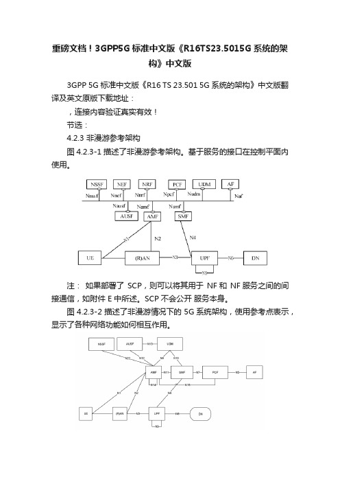
重磅文档!3GPP5G标准中文版《R16TS23.5015G系统的架构》中文版3GPP 5G标准中文版《R16 TS 23.501 5G系统的架构》中文版翻译及英文原版下载地址:,连接内容验证真实有效!节选:4.2.3 非漫游参考架构图 4.2.3-1 描述了非漫游参考架构。
基于服务的接口在控制平面内使用。
注:如果部署了SCP,则可以将其用于NF和 NF服务之间的间接通信,如附件 E中所述。
SCP不会公开服务本身。
图 4.2.3-2 描述了非漫游情况下的 5G系统架构,使用参考点表示,显示了各种网络功能如何相互作用。
注 1: N9,N14未在所有其他图中示出,但是它们也可适用于其他场景。
注 2:为了清楚地说明点对点图,未描述 UDSF,NEF和 NRF。
但是,所有描述的网络功能都可以根据需要与 UDSF,UDR,NEF和NRF进行交互。
注3:UDM使用用户数据和认证数据,PCF使用可能存储在UDR中的策略数据(参见第 4.2.5节)。
注 4:为清楚起见,UDR及其与其他 NF的连接(例如 PCF)未在点对点和基于服务的架构图中描述。
有关数据存储体系结构的更多信息,请参见第 4.2.5节。
注 5:为清楚起见,NWDAF及其与其他 NF的连接,例如 PCF,未在点对点和基于服务的架构图中描述。
有关网络数据分析体系结构的更多信息,请参见第 4.2.9节。
图 4.2.3-3 描述了 UE 使用参考点表示同时访问使用多个 PDU会话的两个(例如本地和中央)数据网络的非漫游架构。
此图显示了多个PDU会话的体系结构,其中为两个不同的PDU会话选择了两个SMF。
但是,每个SMF 还可以具有在PDU 会话内控制本地和中央UPF 的能力。
图 4.2.3-4 描述了在使用参考点表示在单个 PDU会话内提供并发接入到两个(例如本地和中央)数据网络的情况下的非漫游体系结构。
图 4.2.3-5 描述了使用参考点表示的网络开放功能的非漫游架构。
3gpp标准 文档
3GPP标准概述和组织架构首先3GPP标准化组织主要包括项目合作组(PCG)和技术规范组(TSG)两类。
其中PCG工作组主要负责3GPP总体管理、时间计划、工作的分配等,具体的技术工作则由各TSG工作组完成。
目前,3GPP包括3个TSG,分别负责EDGE无线接入网(GERAN)、无线接入网(RAN)、系统和业务方面(SA)、核心网和终端(CT)。
每一个TSG进一步分为不同的工作子组,每个工作子组分配具体的任务。
例如SA WG1负责需求制定,SA WG2负责系统架构,SA WG3负责安全,SA WG5负责网络管理等等。
又如,TSG RAN 划分为5个工作小组,分别是RAN层1规范组、层2和层3规范组、lub/Lur/Lu规范与OAM需求规范组。
无线性能与协议规范组和终端一致性测试规范组。
目前,3GPP已经正式发布R99、R4、R5、R6、R7、R8共6个版本。
R8版本于2009年3月正式发布,R9的标准工作也已正式启用。
其中,R99-R7版本已基本稳定,R8部分特征正在完善过程中。
另外,3GPP相关的标准工作可以分为两个阶段:SI(Study Item,技术可行性研究阶段)和WI(Work Item,具体技术规范撰写阶段)。
SI阶段主要以研究的形式确定系统的基本框架,并进行主要的候选技术选择,以对标准化的可行性进行判断。
WI阶段分为Stage2、Stage3两个子阶段。
其中,Stage2主要通过对SI阶段中初步讨论的系统框架进行确认,同时进一步完善技术细节。
该阶段规范并不能够直接用于设备开发,而是对系统的一个总体描述,仅是一个参考规范,根据Stage2形成的初步设计,进一步验证了系统的性能。
Stage3主要是确定具体的流程、算法及参数等。
3GPP各版本针对核心网的演进1 R99阶段:这是3G标准的第一个阶段,2000年3月发布。
延续了GSM/GPRS系统的核心网系统结构,即分为电路域和分组域分别处理语音和数据业务。
(完整word版)3GPP协议中文版-001

(完整word版)3GPP协议中文版-001前言本通信标准参考性技术文件主要收集了与定义IMT-DS FDD(WCDMA)系统的目标和系统结构的基本文档相关的术语、定义和缩略语。
本文基于 3GPP制订的Release—99(2000年9月份版本)技术规范,具体对应于TS 25.990 V3。
0。
0。
本参考性技术文件由信息产业部电信研究院提出.本参考性技术文件由信息产业部电信研究院归口.本参考性技术文件起草单位:信息产业部电信传输研究所本参考性技术文件主要起草人:徐京皓徐菲卓天真续合元盛蕾吴伟本参考性技术文件2001年1月首次发布。
本参考性技术文件委托无线通信标准研究组负责解释.通信标准参考性技术文件IMT—DS FDD(WCDMA)系统无线接口物理层技术规范:名语术语IMT—DS FDD(WCDMA) System Radio Interface Technical Specification:Vocabulary1 范围本通信标准参考性技术文件介绍了与定义IMT-DS FDD(WCDMA)系统的目标和系统结构的基本文档相关的术语,定义和缩略语。
这篇文档也为以后的技术规范的工作提供了一个工具,以便于理解。
在这篇文档中所给出的术语,定义和缩略语或者是从现在的文档(ETSI,ITU或其它)引入的,或者是在需要精确的词汇时新创造出来的。
2 引用标准下列标准所包含的条文,通过在本标准中引用而成为本文件的条文。
本文件出版时,所示版本均为有效。
所有标准都会被修订,使用本文件的各方应探讨使用下列标准最新版本的可能性。
3 与UTRA相关的术语和定义AAcceptable Cell可接受的小区:是指UE可以驻留并进行紧急呼叫的小区.它必须满足特定的条件。
Access Stratum;接入层;Access Stratum SDU (Service Data Unit)接入层SDU(业务数据单元):在核心网或UE的接入层SAP(业务接入点)上传送的数据单元。
3GPP协议导读
3GPP协议导读项目名称文档编号版本号V0.0.2作者徐莉版权所有大唐移动通信设备有限公司本资料及其包含的所有内容为大唐移动通信设备有限公司(大唐移动)所有,受中国法律及适用之国际公约中有关著作权法律的保护。
未经大唐移动书面授权,任何人不得以任何形式复制、传播、散布、改动或以其它方式使用本资料的部分或全部内容,违者将被依法追究责任。
文档更新记录目录1引言 (5)1.1 编写目的 (5)1.2 目的 (5)1.3 预期读者和阅读建议 (5)1.4 文档约定 (5)1.5 参考资料 (5)1.6 缩写术语 (5)2文档的结构 (6)33GPP协议概述 (6)3.1 3GPP及其协议版本 (6)3.2 3GPP协议的标识 (6)3.3 一个3GPP协议的结构 (9)4与CN相关的3GPP协议介绍 (10)4.1 21S ERIES (10)4.2 22S ERIES (10)4.3 23S ERIES (11)4.4 24S ERIES (13)4.5 25S ERIES (14)4.6 26S ERIES (15)4.7 29S ERIES (16)4.8 32S ERIES (19)4.9 33S ERIES (27)4.10 35S ERIES (28)4.11 41S ERIES (29)4.12 42S ERIES (29)4.13 43S ERIES (30)4.14 44S ERIES (31)4.15 48S ERIES (31)4.16 49S ERIES (33)4.17 52S ERIES (33)4.18 补充业务相关协议 (33)4.18.1 增强的多级优先和占先(eMLPP)业务 (34)4.18.2 线路标识类 (34)4.18.3 呼叫前转类 (35)4.18.4 呼叫完成类 (35)4.18.5 多方类 (36)4.18.6 CUG类 (36)4.18.7 计费通知类 (36)4.18.8 呼叫闭锁类 (36)4.18.9 CD (37)4.18.10 UUS (37)4.18.11 ECT (38)4.18.12 CCBS (38)4.18.13 名字标识类 (38)4.18.14 Multicall (38)4.19 ODB相关协议 (39)4.20 GPRS相关协议 (39)4.21 CAMEL相关协议 (39)4.22 S UPPOR T OF O PTIMAL R OUTEING相关协议 (39)4.23 U NSTRUCTURED S UPPLEMENTAR Y S ER VI CE D ATA (USSD)相关协议 (40)4.24 MMS相关协议 (40)4.25 IMS相关协议 (40)4.25.1 IMS阶段1的协议 (40)4.25.2 IMS阶段2的协议 (40)4.25.3 IMS阶段3的协议 (41)4.25.4 支持IMS的CAMEL协议 (41)4.25.5 IMS对组管理的支持 (42)4.25.6 IMS对消息业务的支持 (42)4.25.7 IMS对Presence业务的支持 (42)4.25.8 IMS对会议业务的支持 (42)4.25.9 IMS与IP网络的互通 (43)4.25.10 IMS与CS域的互通 (43)4.25.11 IMS基于本地策略的服务和QoS管理 (43)4.25.12 IMS的计费 (43)4.26 LCS相关协议 (43)4.27 OSA相关协议 (44)4.28 3GPP系统与WLAN互通相关协议 (44)4.29 MBMS相关协议 (44)4.30 F OLLOW M E SERVI CE相关协议 (45)4.31 TFO相关协议 (45)附录: (46)大唐移动通信设备有限公司 3GPP协议导读1 引言本文档描述了3GPP协议的协议标识方式和版本标识方式,并对3GPP 21系列、22系列、23系列、24系列、25.41x系列、26系列、28系列、29系列、32系列、33系列、35系列、41系列、42系列、43系列、44系列、48系列、49系列、52系列与核心网有关的协议进行了介绍,给出了阅读建议。
3gpp协议中文目录
3gpp协议中文目录篇一:3GPP 24008中文版协议1. 简述该文档描述了第三代移动通信系统和数字小区通信系统内用在无线接口的核心网协议流程。
主要描述了无线接口上的流程(参考接口Um或Uu,参考跑3GPP 24.002或3GPP 23.002)比如呼叫控制CC, 移动性管理MM,和会话管理SM。
文中每当提及further study或FS或FFS的地方表示本文不会对相应的内容作标准阐述。
这些流程都是按照无线接口的控制信道上交换的信令定义的。
控制信道在3GPP 44.003和3GPP 25.301中描述。
该协议的功能性描述和流程,以及其他层和实体间的交互将在3GPP 24.007中描述。
1.3 层3流程的结构可以用“积木”法来描述层3的流程。
基础的积木是三个子层的协议控制实体提供的“基本流程”,这些子层是无线资源管理RRM,移动性管理MM和连接管理CM。
11.5 在A/Gb模式下逻辑信道的使用逻辑信道在3GPP 45.002中定义。
下述的这些控制信道都是承载信令信息或指定类型的用户分组数据:1) 广播控制信道BCCH:下行,用来广播小区独有信息2) 同步信道SCH:下行,用来广播同步信息和BSS标识信息3) 寻呼信道PCH:下行,用来发送寻呼给MS4) 随机接入信道RACH:上行,用来请求一条专用控制信道DCCH5) 接入允许信道AGCH:下行,用来分配一条专用控制信道DCCH6) 独立专用控制信道SDCCH:双向7) 快速辅助控制信道FACCH:双向,和一条业务信道TCH关联8) 慢速辅助控制信道SACCH:双向,和一条SDCCH或者TCH关联9) 小区广播信道CBCH:下行,用作非点对点短消息传输10) 指示信道NCH:下行,用来通知用户VBS呼叫或VGCS呼叫信令层2定义了两个服务接入点,以SAPI划分(详见3GPP 44.006)21) SAPI0:支持包括用户消息的信令信息的传输2) SAPI3:支持用户短消息的传输层3根据每条消息进行SAP的选择,以及逻辑控制信道的选择,L2操作模式(确认模式AM,非确认模式UM或随机接入)的选择。
3GPP协议阅读指南7页word

1协议阅读指南1.1协议的框架如下图所示,在第三代移动通讯体系中,目前主要有两大阵营,即WCDMA 与CDMA2000(其他一些小的阵营我们几乎可以不用关心,此处不再提及。
另,TD-SCDMA可以认为是WCDMA阵营中的一种无线技术)。
WCDMA的协议是由3GPP标准化组织制定的,而CDMA2000是由3GPP2标准化组织制定的,所以有时也用3GPP代指WCDMA,用3GPP2代指CDMA2000。
在第二代移动通讯体制中,也主要有两大阵营,即GSM与窄带CDMA(IS-95)。
由GSM向3G过渡是走的WCDMA技术路线,由IS-95CDMA向3G过渡是走CDMA2000的路线。
我们这个项目将要做的是WCDMA的基站(Node B),所以与我们直接相关的协议是3GPP的协议。
3GPP的协议分为3个版本,即R99与R4、R5,R99是第一阶段的版本,计划于2000年6月定型(FROZEN),以后只作一些微小的修改,但实际上到目前为止还没有完全定型。
2001年3月版的R99可以认为已经大部分定型。
而R4目前正处在标准化的阶段,2001年3月已经有一个初步定型的规范。
我们要实现的就是R99(下图中加粗黑框部分)。
R99目前有5个版本,即2000年3月份版本、6月份版本、9月份版本、12月份版本和2001年3月份版本,我们应该阅读的是9月份的版本(3GPP2000.9),3月份版本与6月份版本可以作为参考。
大家阅读协议时可以看到,3月份与6月份的版本是从21系列开始的,9月份是从01系列开始的,为什么会这样呢?因为3GPP的协议(特别是CN侧协议)是在GSM与GPRS基础上发展的,3GPP的协议引用了很多GSM的协议,在9月份的版本中,3GPP将部分引用到的GSM的协议转化为3GPP的协议,所以在9月份的目录中多了01~12系列的协议(GSM协议是从01~12)。
大家可以认为,“真正的”3GPP的协议还是从21系列开始的(当然,GSM的01~12系列也是3GPP协议的一部分)。
LTE中文协议LTE_3GPP_36.213860(中文版)综述

3GPP TS 36.213 V8.6.0 (2009-03)Technical Specification3rd Generation Partnership Project;Technical Specification Group Radio Access Network;Evolved Universal Terrestrial Radio Access (E-UTRA);Physical layer procedures(Release 8)The present document has been developed within the 3rd Generation Partnership Project (3GPP TM) and may be further elaborated for the purposes of 3GPP. The present document has not been subject to any approval process by the 3GPP Organisational Partners and shall not be implemented.This Specification is provided for future development work within 3GPP only. The Organisational Partners accept no liability for any use of this Specification. Specifications and reports for implementation of the 3GPP TM system should be obtained via the 3GPP Organisational Partners’ Publications Offices.KeywordsUMTS, radio, layer 13GPPPostal address3GPP support office address650 Route des Lucioles – Sophia AntipolisValbonne – FranceTel.: +33 4 92 94 42 00 Fax: +33 4 93 65 47 16InternetCopyright NotificationNo part may be reproduced except as authorized by written permission.The copyright and the foregoing restriction extend to reproduction in all media.© 2009, 3GPP Organizational Partners (ARIB, ATIS, CCSA, ETSI, TTA, TTC).All rights reserved.UMTS™ is a Trade Mark of ETSI registered for the benefit of its members3GPP™ is a Trade Mark of ETSI registered for the benefit of its Members and of the 3GPP Organizational PartnersLTE™ is a Trade Mark of ETSI currently being registered for the benefit of i ts Members and of the 3GPP Organizational Partners GSM® and the GSM logo are registered and owned by the GSM AssociationContentsForeword (5)1Scope (6)2References (6)3Definitions, symbols, and abbreviations (7)3.1Symbols (7)3.2Abbreviations (7)4Synchronisation procedures (8)4.1Cell search (8)4.2Timing synchronisation (8)4.2.1Radio link monitoring (8)4.2.2Inter-cell synchronisation (8)4.2.3Transmission timing adjustments (8)5Power control (9)5.1Uplink power control (9)5.1.1Physical uplink shared channel (9)5.1.1.1UE behaviour (9)5.1.1.2Power headroom (12)5.1.2Physical uplink control channel (12)5.1.2.1UE behaviour (12)5.1.3Sounding Reference Symbol (14)5.1.3.1UE behaviour (14)5.2Downlink power allocation (15)5.2.1 eNodeB Relative Narrowband TX Power restrictions (16)6Random access procedure (16)6.1Physical non-synchronized random access procedure (16)6.1.1Timing (17)6.2Random Access Response Grant (17)7 Physical downlink shared channel related procedures (18)7.1UE procedure for receiving the physical downlink shared channel (19)7.1.1 Single-antenna port scheme (21)7.1.2Transmit diversity scheme (21)7.1.3Large delay CDD scheme (22)7.1.4Closed-loop spatial multiplexing scheme (22)7.1.5Multi-user MIMO scheme (22)7.1.6Resource allocation (22)7.1.6.1Resource allocation type 0 (22)7.1.6.2Resource allocation type 1 (23)7.1.6.3Resource allocation type 2 (24)7.1.7Modulation order and transport block size determination (25)7.1.7.1Modulation order determination (25)7.1.7.2Transport block size determination (26)7.1.7.2.1Transport blocks not mapped to two-layer spatial multiplexing (27)7.1.7.2.2Transport blocks mapped to two-layer spatial multiplexing (32)7.1.7.2.3Transport blocks mapped for DCI Format 1C (33)7.1.7.3Redundancy Version determination for Format 1C (33)7.2UE procedure for reporting channel quality indication (CQI), precoding matrix indicator (PMI) and rankindication (RI) (33)7.2.1Aperiodic CQI/PMI/RI Reporting using PUSCH (36)7.2.2Periodic CQI/PMI/RI Reporting using PUCCH (40)7.2.3Channel quality indicator (CQI) definition (46)7.2.4Precoding Matrix Indicator (PMI) definition (48)7.3UE procedure for reporting ACK/NACK (49)8Physical uplink shared channel related procedures (52)8.1Resource Allocation for PDCCH DCI Format 0 (54)8.2UE sounding procedure (55)8.3UE ACK/NACK procedure (57)8.4UE PUSCH Hopping procedure (58)8.4.1 Type 1 PUSCH Hopping (59)8.4.2 Type 2 PUSCH Hopping (59)8.5UE Reference Symbol procedure (60)8.6Modulation order, redundancy version and transport block size determination (60)8.6.1Modulation order and redundancy version determination (60)8.6.2Transport block size determination (61)8.6.3Control information MCS offset determination (61)8.7UE Transmit Antenna Selection (63)9Physical downlink control channel procedures (64)9.1UE procedure for determining physical downlink control channel assignment (64)9.1.1 PDCCH Assignment Procedure (64)9.1.2 PHICH Assignment Procedure (65)9.2PDCCH validation for semi-persistent scheduling (66)10Physical uplink control channel procedures (67)10.1UE procedure for determining physical uplink control channel assignment (67)10.2Uplink ACK/NACK timing (72)Annex A (informative): Change history (74)ForewordThis Technical Specification (TS) has been produced by the 3rd Generation Partnership Project (3GPP).The contents of the present document are subject to continuing work within the TSG and may change following formal TSG approval. Should the TSG modify the contents of this present document, it will be re-released by the TSG with an identifying change of release date and an increase in version number as follows:Version x.y.zwhere:x the first digit:1 presented to TSG for information;2 presented to TSG for approval;3 or greater indicates TSG approved document under change control.y the second digit is incremented for all changes of substance, i.e. technical enhancements, corrections, updates, etc.z the third digit is incremented when editorial only changes have been incorporated in the document.1 ScopeThe present document specifies and establishes the characteristics of the physicals layer procedures in the FDD and TDD modes of E-UTRA.2 ReferencesThe following documents contain provisions which, through reference in this text, constitute provisions of the present document.∙References are either specific (identified by date of publication, edition number, version number, etc.) or non-specific.∙For a specific reference, subsequent revisions do not apply.∙For a non-specific reference, the latest version applies. In the case of a reference to a 3GPP document (including a GSM document), a non-specific reference implicitly refers to the latest version of that document in the same Release as the present document.[1] 3GPP TR 21.905: “Vocabulary for 3GPP Specifications”[2] 3GPP TS 36.201: “Evolved Universal Terrestrial Radio Access (E-UTRA); Physical Layer –General Description”[3] 3GPP TS 36.211: “Evolved Universal Terrestrial Radio Access (E-UTRA); Physical channels andmodulation”[4] 3GPP TS 36.212: “Evolved Universal Terrestrial Radio Access (E-UTRA); Multiplexing andchannel coding”[5] 3GPP TS 36.214: “Evolved Universal Terrestrial Radio Access (E-UTRA); Physical layer –Measurements”[6] 3GPP TS 36.101: “Evolved Universal Terrestrial Radio Access (E-UTRA); User Equipment (UE)radio transmission and reception”[7] 3GPP TS 36.104: “Evolved Universal Terrestrial Radio Access (E-UTRA); Base Station (BS)radio transmission and reception”[8] 3GPP TS36.321, “Evolved Universal Terrestrial Radio Access (E-UTRA); Medium AccessControl (MAC) protocol specification”[9] 3GPP TS36.423, “Evolved Universal Terrestrial Radio Access (E-UTRA); X2 ApplicationProt ocol (X2AP)”[10] 3GPP TS36.133, “Evolved Universal Terrestrial Radio Access (E-UTRA); Requirements forsupport of radio resource management”[11] 3GPP TS36.331, “Evolved Universal Terrestrial Radio Access (E-UTRA); Radio ResourceControl (RRC) protocol s pecification”3Definitions, symbols, and abbreviations3.1SymbolsFor the purposes of the present document, the following symbols apply:DLRBN Downlink bandwidth configuration, expressed in units of RBsc N as defined in [3]ULRB N Uplink bandwidth configuration, expressed in units of RBsc N as defined in [3]ULsymb N Number of SC-FDMA symbols in an uplink slot as defined in [3]RB scN Resource block size in the frequency domain, expressed as a number of subcarriers as defined in[3]s TBasic time unit as defined in [3]3.2 AbbreviationsFor the purposes of the present document, the following abbreviations apply. ACK Acknowledgement BCH Broadcast ChannelCCE Control Channel Element CQI Channel Quality Indicator CRC Cyclic Redundancy Check DAI Downlink Assignment Index DL DownlinkDTX Discontinuous Transmission EPRE Energy Per Resource Element MCS Modulation and Coding Scheme NACK Negative Acknowledgement PBCH Physical Broadcast ChannelPCFICH Physical Control Format Indicator Channel PDCCH Physical Downlink Control Channel PDSCH Physical Downlink Shared ChannelPHICH Physical Hybrid ARQ Indicator Channel PRACH Physical Random Access Channel PRB Physical Resource BlockPUCCH Physical Uplink Control Channel PUSCH Physical Uplink Shared Channel QoS Quality of Service RBG Resource Block Group RE Resource Element RPF Repetition Factor RS Reference SignalSIR Signal-to-Interference RatioSINRSignal to Interference plus Noise Ratio SPS C-RNTI Semi-Persistent Scheduling C-RNTI SRS Sounding Reference Symbol TA Time alignmentTTI Transmission Time Interval UE User Equipment ULUplinkUL-SCH Uplink Shared Channel VRBVirtual Resource Block4 同步过程4.1 小区搜索小区搜索是指UE在小区中获取时间和频率同步并检测小区物理层Cell ID的过程。
3GPP 协议结构
• 第二层分为如下子层:MAC、RLC、分组 数据集中协议PDCP和广播/组播控制BMC。 • 第三层和RLC分成用户和控制平面。PDCP 和BMC只存在于用户平面中。在控制平面 中,第三层分成若干子层,与第二层相接 口的最低层的子层叫RRC。 • RLC子层提供ARQ功能和无线传输技术。
规范号码 TS25.201
TS25.213
扩频和调制
TS25.214
物理层过程
TS25.215
物理层测量
?传输信道?物理信道和它的结构?同一链路的不同物理信道的相对时间和上行链路与下行链路的相关时间间?从传输信道到物理信道的映射ts25212复用和信道编码介绍在fdd模式下的复用信道编码和交织并详细介绍
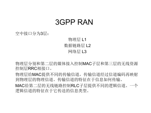
3GPP RAN
空中接口分为3层:
物理层 L1 数据链路层 L2 网络层 L3 物理层分别和第二层的媒体接入控制MAC子层和第三层的无线资源 控制层RRC相接口。 物理层给MAC提供不同的传输信道,传输信道经过信道编码再映射 到物理层的物理信道。传输信道的特征在于信息如何传输。 MAC给第二层的无线链路控制RLC子层提供不同的逻辑信道。一个 逻辑信道的特征在于它传送的信息类型。
名字 物理层-综述
概要 表述第一层的文档的内容
设立第一层的传输信道和物理信道 在FDD模式下的特征,并详细介绍: •传输信道 •物理信道和它的结构 •同一链路的不同物理信道的相对时 间和上行链路与下行链路的相关时 间 •从传输信道到物理信道的映射 介绍在FDD模式下的复用、信道编 码和交织,并详细介绍: •传输信道的编码和复用 •信道编码变化 •第一层的控制信息的编码 •不同交织速率的匹配 •物理信道的分割和映射
TS25.211
物理信道 传输信道到物理信 道的映射
3GPP LTE协议

3GPP LTE无线接口协议及体系结构2 LTE无线接入网体系结构3GPP在考虑LTE技术时,演进型接入网EUTRAN(Evolved Universal Terrestrial Radio Access Network)采用只有演进型Node B(eNB)构成的单层结构,以便简化网络和减少时延,这种结构实际上已经趋近于典型的IP宽带网结构,其无线接入网体系构架如图1所示。
图1 E-UTRAN 体系结构每个eNB都具有一系列功能和相应物理接口,其中包括演进型UTRA用户面(U-plane)(PDCP/RLC/MAC/PHY)和控制面(C-plane)(RRC)协议,多个eNBs通过X2接口相互连接。
就外部连接而言,eNB通过S1接口连接到演进型分组核心EPC(Evolved Pocket Core),具体来说就是通过S1-MME接口连接到移动性管理实体MME(Mobility Management Entity)和通过S1-U接口连接到SAE网关,其中S1接口支持在eNBs和MME/SAE网关之间多对多的链接。
如图2所示,S1接口是EUTRAN和EPC之间的接口,该接口包含两部分:控制面和用户面。
控制面接口S1-MME 是eNB和MME之间的接口,用户面接口S1-U是eNB和SAE网关之间的接口,它在eNB和SAE网关之间提供了非保证的用户面分组数据单元PDU(Packet Data Unit)传送。
图2 3GPP LTE无线接口协议结构S1接口具有以下主要功能:◆SAE业务承载管理功能,包括承载业务的设置和释放等;◆用户设备在激活状态下的移动性管理功能,包括LTE内部的小区切换以及和 3GPP内其它无线接入技术之间的切换;◆寻呼功能,包括发送寻呼请求到所有UE注册的小区;◆非接入层NAS信令传送功能;◆S1接口管理功能,包括差错指示等;◆网络共享功能;◆漫游与地区限制功能;◆NAS节点选择功能;◆初试化用户设备UE的信息内容设置功能,其中包括SAE承载内容、安全性内容、漫游限制、UE容量信息、UE的S1信令连接ID等等。
3gpp协议下载

3gpp协议下载
3GPP是第三代合作伙伴计划(3rd Generation Partnership Project)的缩写。
3GPP是一个国际组织,由全球各地的手机运营商、手机制造商、通讯设备供应商和其他相关行业的组织联合组成。
该组织的主要目标是制定全球通信标准和规范,以确保移动通信在全球范围内的互操作性和互联互通。
3GPP协议是移动通信领域的标准化技术协议之一,目前在全球范围内得到广泛地应用。
它包含了一系列技术规范和标准,涵盖了从2G到5G的通信技术,如GSM、GPRS、EDGE、UMTS、LTE、5G NR等。
为了更好地了解和使用3GPP协议,用户可以通过3GPP 官网下载相关的技术规范和标准文件。
3GPP官网提供了多种文件下载方式,如ZIP文件、PDF文件、Word文档等,用户可以根据自己的需求选择适合的下载方式。
在3GPP官网中,用户可以找到各种3GPP协议的技术规范和标准文件,如LTE技术规范、5G NR技术规范、IMS技术规范、VoLTE技术规范等。
这些文件涵盖了从通信协议、接口规范、网络架构、信令协议、安全机制等方面的内容,可以为用户提供广泛的技术支持和参考。
除了3GPP官网外,用户还可以在一些技术网站、技术论坛中寻找相关的3GPP协议资料。
但是,在下载这些资料时,用户应该注意保持警惕,以防万一下载到了一些病毒或者恶意软件。
总之,3GPP协议是移动通信领域的重要技术标准之一,用户可以通过3GPP官网等途径下载相关的技术规范和标准文件,以便更好地了解和使用这些协议。
- 1、下载文档前请自行甄别文档内容的完整性,平台不提供额外的编辑、内容补充、找答案等附加服务。
- 2、"仅部分预览"的文档,不可在线预览部分如存在完整性等问题,可反馈申请退款(可完整预览的文档不适用该条件!)。
- 3、如文档侵犯您的权益,请联系客服反馈,我们会尽快为您处理(人工客服工作时间:9:00-18:30)。
前言本通信标准参考性技术文件主要收集了与定义IMT-DS FDD(WCDMA)系统的目标和系统结构的基本文档相关的术语、定义和缩略语。
本文基于 3GPP制订的Release-99(2000年9月份版本)技术规范,具体对应于TS 25.990 V3.0.0。
本参考性技术文件由信息产业部电信研究院提出。
本参考性技术文件由信息产业部电信研究院归口。
本参考性技术文件起草单位:信息产业部电信传输研究所本参考性技术文件主要起草人:徐京皓徐菲卓天真续合元盛蕾吴伟本参考性技术文件2001年1月首次发布。
本参考性技术文件委托无线通信标准研究组负责解释。
通信标准参考性技术文件IMT-DS FDD(WCDMA)系统无线接口物理层技术规范:名语术语IMT-DS FDD(WCDMA) System Radio Interface Technical Specification:Vocabulary1 范围本通信标准参考性技术文件介绍了与定义IMT-DS FDD(WCDMA)系统的目标和系统结构的基本文档相关的术语,定义和缩略语。
这篇文档也为以后的技术规范的工作提供了一个工具,以便于理解。
在这篇文档中所给出的术语,定义和缩略语或者是从现在的文档(ETSI,ITU或其它)引入的,或者是在需要精确的词汇时新创造出来的。
2 引用标准下列标准所包含的条文,通过在本标准中引用而成为本文件的条文。
本文件出版时,所示版本均为有效。
所有标准都会被修订,使用本文件的各方应探讨使用下列标准最新版本的可能性。
3 与UTRA相关的术语和定义AAcceptable Cell可接受的小区:是指UE可以驻留并进行紧急呼叫的小区。
它必须满足特定的条件。
Access Stratum;接入层;Access Stratum SDU (Service Data Unit)接入层SDU(业务数据单元):在核心网或UE的接入层SAP(业务接入点)上传送的数据单元。
Active mode激活模式:“激活模式”是指UE处理呼叫时所处的状态。
Active Set激活集:在UE和UTRAN接入点之间的一个特定的通信业务所同时涉及的无线链路的集合。
ALCAPALCAP:用于建立和拆除传输承载的传输信令协议的一般性称谓。
Allowable PLMN准入的PLMN:不在UE所禁止的PLMNs列表内的PLMN。
Available PLMN可用的PLMN:指UE找到满足特定条件的小区所处的PLMN。
Average transmit power平均发射功率:在任意特定时间间隔内,包括不发射的时间在内的,发射机输出功率的平均值。
Average Transmitter Power Per Traffic Channel (dBm)每个业务信道的平均发射功率(dBm):在整个发射时间段内的总发射功率的均值。
CCable, Connector, and Combiner Losses (Transmitter) (dB)电缆,连接器和组合器损耗(发射方)(dB):在发射机输出和天线输入之间的所有发射系统元件的组合损耗(所有的损耗以正的dB值表示)。
Cable, Connector, and Splitter Losses (Receiver) (dB)电缆,连接器和分离器损耗(接收方)(dB):在接收天线输出和接收机输入之间的所有发射系统元件的组合损耗(所有的损耗以正的dB值表示)Call Control;呼叫控制;Camped on a cell驻留在一个小区:UE处于空闲模式,已经完成了小区选择/再选择过程,并已经选择了一个小区。
UE监控系统信息,和(在多数情况下)寻呼信息。
注意此时业务可能被限制,而且在被选择的小区内,PLMN可能不知道UE的存在。
Cell小区:小区是一个地理区域,可以由用户设备通过UTRAN接入点广播的识别符进行识别。
Coded Composite Transport Channel (CCTrCH)码组合传输信道(CCTrCH):通过一个或多个传输信道的编码和复用而产生的一个数据流。
Common Channel公共信道:不是专用于某一特定UE的信道。
Control channel控制信道:“控制信道”是一个用于运送系统控制信息的逻辑信道。
Controlling RNC控制RNC:特指一个与一组特定的UTRAN接入点集合相关的RNC。
对任何一个UTRAN接入点,只存在一个控制RNC。
控制RNC将全面控制UTRAN接入点的逻辑资源。
Coverage area覆盖区域:覆盖区域是指一个区域,提供给该区域的UMTS业务的业务概率在某一特定的门限之上。
DDedicated Channel专用信道:一个专用于某一特定UE的信道。
Downlink下行链路:从UTRAN接入点到UE进行信号传输的单向无线链路。
一般来说其方向是从网络到用户设备。
Drift RNS漂移RNS:特指一个与UE和UTRAN之间的特定连接相关的RNS。
当UTRAN和用户设备间的连接需要使用由RNS控制的小区时,该RNS用无线资源来支持服务RNS,则称此RNS为漂移RNS。
DRX cycleDRX周期:读取发给某一特定UE的初始寻呼信息之间的时间间隔。
EExplicit Diversity Gain (dB)明确的分集增益(dB):通过使用分集技术而得到的有效的增益。
HHandoff Gain/Loss (dB)切换增益/损耗(dB):这是在小区边界为确保通话的可靠性而进行切换时所带来的增益/损耗因子(+或-)。
Handover切换:将一个用户的连接从一个无线信道转到另一个无线信道的过程(可以在同一小区内或不同小区间进行)。
Hard Handover硬切换:硬切换是指这样一类切换过程,即在新的无线链路建立之前,UE内的所有的旧的无线链路都已被放弃。
Home PLMN归属PLMN:一个PLMN的移动国家码(MCC)和移动网络码(MNC)与IMSI的MCC和MNC一致时,则称该PLMN为归属PLMN。
IIdle mode空闲模式:UE被打开但没有建立任何RRC连接的状态。
Information Data Rate信息数据速率:必须通过空中接口发射的用户信息的速率。
例如:声码器的输出速率。
Initial paging information初始寻呼信息:这个信息指出UE是否需要继续读取更多的寻呼信息,并最终接收到一条寻呼消息。
Initial paging occasion初始寻呼时刻:UE用初始寻呼时刻作为它的DRX周期的起始点。
Inter-cell handover小区间切换:不同小区间的切换。
一个小区间切换要求改变网络连接。
Interference Signal Code Power (ISCP)干扰信号码功率(ISCP):当只接收到干扰功率时,给出此值。
这个值是指接收到的信号在解扩和合并后的平均功率。
Intra-cell handover小区内切换:一个扇区内或同一小区内不同扇区间的切换。
小区内切换不要求改变网络连接。
IuIu:在RNC和核心网间的互连节点。
也可认为是一个参考节点。
IubIub:RNC和Node B之间的接口。
IurIur:两个RNC之间的逻辑接口。
在逻辑上它可表示为RNCs间的点到点链路,而在物理实现上可以不是一个点到点的链路。
LLocation Registration (LR)位置登记(LR):UE在一个登记区内进行登记,举例来说,可以是定期地进行登记,也可以是在进入一个新的登记区时进行登记。
Logical Channel逻辑信道:是指一个在无线接口上传送特定类型信息的信息流。
逻辑信道是在MAC层上提供的Logical Model逻辑模型:一个逻辑模型是对一个网络、网络元素、网络元素的集合、元素间的拓扑逻辑关系、连接的端点(终止点)、在两个或更多终端节点间传送信息的传送实体的抽象定义,网络元素是通过网络元素的信息对象来表示的。
在逻辑模型中定义的信息对象将被连接管理功能所使用。
这样可实现一个相对独立的物理实施的管理方式。
Logical O&M逻辑O&M:逻辑O&M是逻辑资源(信道,小区)控制的随路信令,它属于RNC,但在物理上由Node B来实现。
RNC控制这些逻辑资源。
许多O&M过程在物理上是在Node B上实现,但是它们对逻辑资源发生影响,因而需要RNC和Node B间的信息交换。
支持此信息交换所需的所有消息都归类为逻辑O&M,并成为NBAP的一个完整部分。
LSALSA:局部化的业务区。
LSA是一个由运营者定义的区域,对于这个区域,使用一些特定的接入条件。
这可以与一个由核心网提供特别业务的区域相对应。
LSA可以在PLMN内定义,也可以在全球范围内定义。
因而,LSA可以提供一个非连续的无线覆盖。
MMacro cells宏小区:小区半径较大的室外小区称为宏小区。
Macro diversity handover宏分集切换:宏分集为一种运行状态,在这种状态下,用户设备将与两个或更多个UTRAN接入点同时有无线链路的连接,其唯一的目的是提高无线连接的质量或提供无缝覆盖。
Maximum output Power最大输出功率:指在最大功率设置时的平均功率。
Maximum peak power最大峰值功率:指运行在给定的最大输出功率时所测到的峰值功率。
Maximum Power Setting最大功率设定:指功率控制设定可以使用的最大值。
Maximum Total Transmitter Power (dBm)最大总发射机功率(dBm):所有信道上的最大发射功率的总和。
Maximum Transmitter Power Per Traffic Channel (dBm)每个业务信道上的最大发射机功率(dBm):发射机在单个业务信道上输出的最大功率。
Medium Access Control ;媒质接入控制;Micro cells微小区:“微小区”是半径较小的小区。
Mobile evaluated handover移动台估值的切换:MEHO是一种由移动台进行估值来触发的切换。
移动台根据对无线环境的测量并基于网络定义的准则来估计切换的必要性。
当估计的值满足切换的要求时,移动台将向网络发送必要的信息。
网络根据汇报上来的估计的结果和其它条件,例如上行链路的无线环境和/或网络资源的可用性,来确定切换的必要性,然后网络可以执行切换。
Mobile Station移动台:一个“移动台”(MS)是指能通过一个或多个无线接口接入到一系列UMTS业务的实体。
在UMTS 服务区域内,此实体可以是静止不动的,也可以处于运动当中,可同时为一个或多个用户提供服务。