安捷伦 电流探头 型号1147B
Agilent P3111 pH Electrode 用户手册说明书

Agilent P3111 pH Electrode pH 电极Operating Guide 用户手册OverviewThe P3111 pH Electrode can measure pH values. It is used withthe 3200P meter or similar meters, with the R8111 or similarreference electrode.Use this electrode according to the operating manual toavoid personal injury.The electrode solution can cause chemical burns orillness if it is taken orally or contacted by human skin.Use protective clothing or gloves to avoid contact. Incase of contact, rinse contacted area with tap water ordeionized water thoroughly.The electrode body material is glass. Handle with care toavoid damage to the instrument.SpecificationsTable 1P3111 pH Electrode specificationsSpecification ValuepH range0 to 147.00 ± 0.5Zero potential pH with R8111reference electrodeTemperature range0 to 60 ºCElectrode impedance< 250 MBody material GlassElectrode diameter12 mmElectrode length120 mmCable interface BNCCable length1000 mmFigure 1P3111 pH Electrode assemblyOperationPreparing the electrode1Remove the storage bottle and cap from the electrode and store it upright for future use.2Rinse the measuring tip with distilled or deionized water.3Hold the electrode measuring tip downwards and swing it several times to remove air bubbles near the sensitive glassbulb.Calibration1Connect the electrode and a reference electrode to themeter. Input the temperature of calibration solution accord-ing to the meter operating manual.2Soak the measuring tip in calibration solutions in sequence.Calibrate the electrode according to the procedures listed inthe operating manual.Measurement1Soak the measuring tip in sample solution. When thereading becomes stable, read the value from the meter.2Rinse the measuring tip.Operating hints•The main material of the measuring tip is glass. Ensure the sample solution will not damage the measuring tip beforemeasurement. Solutions containing solids or crystals willdamage the measuring tip.•Keep calibration solution and sample solution flowing at a uniform speed around the electrode or the accuracy may beimpacted.•Do not soak the electrode in a sample solution for an extended time. After measurement, rinse the electrodecarefully.•White powder or crystals that collect on the electrode during measurement or transportation do not affect theperformance of the electrode. Rinse the residue with tap ordeionized water.•The pH of a solution is affected by its temperature.•For acidic sample solutions, use pH 4.00 and 7.00 standards for calibration. For alkaline sample solutions, use pH 7.00and 10.01 standards.•Do not apply force onto the electrode cap, cable or cable interface.•Keep the cable interface dry.MaintenanceCleaning of inorganicsSoak the measuring tip in 0.1 mol/L HCl or EDTA for15 minutes.Cleaning of organicsSoak the measuring tip in ethyl alcohol or another solvent thatcan dissolve organics for 15 minutes.Cleaning of greaseSoak the measuring tip in weakly alkaline detergent for15 minutes.Cleaning of protein precipitationSoak the measuring tip in 0.1 mol/L HCl solution that contains1% pepsin for 15 minutes.Regeneration of the glass sensitive membrane HF is lethal. See the HF material safety data sheet beforeusing it.1Soak the sensitive membrane in 4% HF solution for 3 to5 seconds.2Rinse the membrane in 0.1 mol/L HCl several times.3Rinse with distilled or deionized water.4After one or more cleaning procedures, thoroughly rinse the electrode with distilled or deionized water.5If necessary, empty the reference electrode and add fresh reference solution. Repeat this action 2 or 3 times.6Soak the electrode in pH 4.01 solution for at least one hour.TroubleshootingMetersRefer to the meter operating manual. Check all related parts,such as the electrode, calibration solution, and samples.Electrode1Connect the electrode and a reference electrode to themeter. Set the meter to display mV.2Soak the measuring tip in pH 4.00 and pH 10.01 calibration solutions. When the readings become stable, record mV val-ues respectively.3When the electrode is used with a R8111 reference elec-trode, the absolute value of the difference between thesetwo mV values should be 326–370 mV in total. This indi-cates that the electrode has a good performance. If not, per-form maintenance on the electrode.Accuracy1Choose any two calibration solutions to calibrate a elec-trode. Use effective calibration solution. Make sure the dis-tilled or deionized water used to prepare the solutionsmeets requirements, and the solution is not contaminatedor beyond its shelf life.2Use this electrode to measure the pH value in anothercalibration solution.3Compare the theoretical value of that calibration solution with the measured value.4Ensure the measuring accuracy of the electrode is sufficient for the application.SamplesThe electrode is only suitable for measuring the pH value ofconventional solutions. Nonaqueous reagents or solutionswith low conductivity or high viscosity may have long mea-surement times, which can affect measurement accuracy.For any other problems during electrode use, contact yourAgilent Technologies customer service representative. Storage1Install the electrode storage bottle and cap onto the elec-trode body in sequence.2To protect the measuring tip, keep 5–10 mm between the bottom of the storage bottle and the measuring tip of theelectrode.3Tighten the storage bottle cap.4Place the electrode in the storage box and store at ambient temperature and dry conditions.Agilent P3111 pH 电极用户手册概述实验室常规pH值测量用pH玻璃电极,与R8111参比电极或类似参比电极以及3200P仪器或类似仪器一起配套使用。
安捷伦34970中文说明书
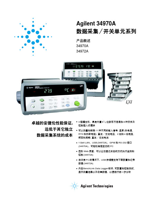
N2780B 电流探头产品简介

Keysight N2780B 系列交流/直流电流探头广泛的电流探头可满足特定的应用需求技术资料―各种带宽: 直流到2 MHz、10 MHz、50 MHz、100 MHz―直流和交流测量―出色的1% 精度和高信噪比―过载保护功能可防止过多输入导致探头损坏―直接连接到示波器的高阻抗 1 MΩBNC 输入―"消磁"按钮可消除磁芯中产生的任何残余磁性―外置电源 N2779A 使您能够把多达三个N278xB 连接在一个电源上N2780B 系列电流探头能够与任意一款支持高阻抗BNC 输入的示波器兼容,是精确、可靠的直流和交流电流测量解决方案。
交流和直流测量混合技术使用包括霍尔效应传感器和交流电流变压器在内的混合技术,该探头可精确测量高达500 Arms 的峰值(N2780B 型号) 或直流至100 MHz (N2783B 型号)的直流或交流电流,且无需断开电路。
通过分裂核心体系结构,该探头可以轻松连接导体和断开连接。
广泛的应用该电流探头具有广泛的测量范围 (高达 500 A)、平坦的频率响应、低噪声和低插入损耗,因此非常适合以下情况下执行电流测量: 测量马达驱动、开关电源、逆变器、控制器、传感器、磁盘驱动器、LCD 显示器、电子镇流器和放大器的稳态或瞬时电流。
N2782B 和N2783B 具有高信噪比,是进行毫安级低电平电流测量的理想工具。
精确的电流测量内置DEMAG (消磁)功能可消除因接通/断开电源开关或输入过多电流在磁芯中生成的残余磁性。
此外,使用零位调整控制可轻松校正探头上的电压偏置或温度漂移。
图1. 配有N2779A 电源的N2780B 系列电流探头图2. N2783B、N2780B、N2781B 和N2782B 电流探头(从左到右)N2779A 3 通道电源技术指标适用的电流探头: N2780B 、N2781B 、N2782B 、N2783B 和 N2774A 电源连接器数量: 3连接器类型: LEMO inc./AC42Z 输出电压: DC (12 V, 2.5 A)最大额定功率: 170 VA所需的输入功率:AC 100-240 VAC, 50/60 Hz, 125-170 VAC上升时间175 ns 或更低35 ns 或更低7 ns 或更低 3.5 ns 或更低最大电流 (连续) RMS 500 A 150 A 30 A 30 A 最大电流峰值 (不连续)700 A 峰值300 A 峰值50 A 峰值50 A 峰值最低测量电流 (直流 ±3% 的精度,示波器设置为 1 mV/div 并启动高分辨率模式)20 mA20 mA5 mA5 mA输出电压比0.01 V/A (100:1)0.01 V/A (100:1)0.1 V/A (10:1)0.1 V/A (10:1)最大输入电压**600 V CAT II,300 V CAT III 600 V CAT II,300 V CAT III 300 V CAT I 300 V CAT I 幅度精度*(直流和 45 至 66 Hz, 额定电流)±1.0% 读数± 500 mA ±1.0% 读数± 100 mA ±1.0% 读数± 10 mA ±1.0% 读数± 10 mA 噪声(使用示波器的 20 MHz 带宽限制滤波器测得)等效于 25 mArms 或更低等效于 25 mArms 或更低等效于 2.5 mArms 或更低等效于 2.5 mArms 或更低灵敏度的温度系数(在 0 °C 到 40 °C 或 32 °F 到 104 °F 的范围内)±2% 或更低±2% 或更低±2% 或更低±2% 或更低外部磁场的影响(在直流到 60 Hz, 400 A/m 磁场内)相当于 800 mA 最大值相当于 150 mA 最大值相当于 20 mA 最大值相当于 5 mA 最大值最大额定功率7.2 VA(就额定电流而言) 5.5 VA(就额定电流而言) 5.6 VA(就额定电流而言) 5.3 VA(就额定电流而言)额定电源电压DC ±12 V ±0.5 V DC ±12 V ±1 V DC ±12 V ±0.5 V DC ±12 V ±0.5 V 可测量导体直径20 mm 直径(0.79"直径)20 mm 直径(0.79"直径) 5 mm 直径(0.2"直径) 5 mm 直径(0.2"直径)可测量导体直径传感器电缆: 约 2 m (78.7")电源线: 约 1 m (39.4")传感器电缆: 约 2 m (78.7")电源线: 约 1 m (39.4")传感器电缆: 约 1.5 m (78.7')电源线: 约 1 m (39.4")传感器电缆约 1.5 m (78.7")电源线: 约 1 m (39.4")兼容的示波器提供 1 M Ω BNC 输入的所有示波器包括 Keysight 1000、3000、InfiniiVision 2000X 、3000X 、5000、6000 和 7000 系列及 Infiniium 8000 和 9000 系列。
AKTApilot

图 6. UV 流动池。
压力和空气传感器 系统有四个压力传感器测定压力。有两个传感器恰好位于柱 前和柱后,可以读出经过柱的压力差异。另外两个压力传感 器位于泵后,以保证在高压下流速快速停止时的安全。在系 统中有两个不同的空气传感器,一个用于加样,另一个用于 柱的保护。 空气传感器使用超声技术检测流经液体中的空气, 与在 AKTA 和 BioProcessTM 系统中使用的空气传感器有相同功 能。
图 8. 用 SOURCE 30 Q 进行精细纯化的 AKTApilot 和 AKTAexplorer 100 的层析图谱。
.5.
AKTApilot
可靠的灭菌
AKTApilot 的灭菌效率经受了灭菌程序的测试,该法用 1 M 氢 氧化钠 (NaOH) 作为杀菌剂进行微生物攻击实验。 系统用包括 由美国药典 United States Pharmacopoeia (USP 25) 推荐的三 个细菌系和一种通常用于生产环境的酵母菌系的溶液感染系 统 (表 1)。USP 25 要求菌落形成单位呈 log 6 减少。
AKTApilot — 系统规格
系统流速 非梯度和梯度 双模式 操作压力 表 1. 攻击的微生物 UV 波长范围
=
FDA 21 CFR Part 11
!"#$%!
!
== = == =
=
!" #$%&'()*$+ !"#$"% !"#$% !
!"#$%&'()*+,-./01234 !"#$%&#'( !"#$ !"#$% !"#$%&'()*+,-$./012
艾默生 3A7114D QUANTM 泄漏传感器 安装手册说明书

3A7114DZH说明书QUANTM ™ 泄漏传感器用于检测 QUANTM 泵中的泄漏。
仅适合专业用途。
用于在普通场所使用的泵的套件用于在爆炸环境或危险(分类)场所使用的泵的套件重要安全说明请在使用或维修该设备之前,阅读本手册以及相关系统手册内所有的警告和说明内容。
妥善保存这些说明。
25F1081 个液位开关传感器 1 个减速器接头2 个弯头旋转接头(1/4 in. NPT ;3/8 in 软管端口)1 个三通接头1 根软管(长 30 in.,外径 3/8 in.)1 个换气阀25F1091 个液位开关传感器2 个弯头旋转接头(1/4 in. NPT ;3/8 in 软管端口)1 个三通接头1 根软管(长 30 in.,外径 3/8 in.)1 个换气阀(仅用于运输。
请丢弃。
)1 个弯头旋转接头(1/4 in. NPT ;1/4 in 软管端口)1 个弯头旋转接头(1/8 in. NPT )1 根软管(长 20 in.,外径 1/4 in.)1个管路套管隔膜维修端口不得在爆炸性环境中打开。
爆炸性环境中使用的泵必须安装了 128658 插头或泄漏传感器套件25F109。
目录相关手册 . . . . . . . . . . . . . . . . . . . . . . . . . . . . . . . . . . .2警告 . . . . . . . . . . . . . . . . . . . . . . . . . . . . . . . . . . . . . .3概览 . . . . . . . . . . . . . . . . . . . . . . . . . . . . . . . . . . . . . .6组件识别 . . . . . . . . . . . . . . . . . . . . . . . . . . . . . . . . . . .6安装 . . . . . . . . . . . . . . . . . . . . . . . . . . . . . . . . . . . . . .7准备泵 . . . . . . . . . . . . . . . . . . . . . . . . . . . . . . . . .7安装泄漏传感器 . . . . . . . . . . . . . . . . . . . . . . . . . .7安装软管和接头 . . . . . . . . . . . . . . . . . . . . . . . . . .9测试泄漏传感器 . . . . . . . . . . . . . . . . . . . . . . . . .12电气示意图 . . . . . . . . . . . . . . . . . . . . . . . . . . . . . . . 13技术规格 . . . . . . . . . . . . . . . . . . . . . . . . . . . . . . . . . 13美国加州第 65 号提案 . . . . . . . . . . . . . . . . . . . . . . . 13固瑞克标准保修 . . . . . . . . . . . . . . . . . . . . . . . . . . . . 14相关手册英文手册编号描述参考3A7637QUANTM 电动马达,修理零件马达手册3A8572QUANTM 泵,说明,工业型号泵手册3A9286QUANTM 泵,说明,卫生型号泵手册3A8946QUANTM 泵,零件,工业型号零件手册3A9287QUANTM 泵,零件,卫生型号零件手册23A7114D警告警告以下为针对本设备的设置、使用、接地、维护及修理的警告。
知用低频交直流电流探头CPL8100AB (600KHz-2MHz)概述

波器,开关处于 OFF 位置。 附件说明
同轴电缆输出线(CK-310):1 米
电压开关打到 ON 位置,电源指示灯点亮为绿色。 根据测试电流大小,通过按键选择合适的量程。
注意:不同的量程对应示波器不同衰减倍数。 按下自动调零按键,实现探头自动调零。调零成功后,蜂鸣器会发出“滴滴”两声;否则
发出“滴”一声长响,表示调零失败。注意外界的磁场可能对本探头的直流零位有轻微 的影响,调零完成后请不要再挪动。 打开电流探头的钳口并夹住被测导体。 注意:电流探头钳口有方向指示,被测电流流向和方向指示相同时输出正,被测电流流 向和方向指示相反时输出负。
第4页
图 3 最大电流 VS 频率特性曲线
图 4 典型的 DC 线性度(0.01V/A 档位)
4.使用方法
将示波器的耦合方式设置为 DC;示波器输入阻抗设置为 1MΩ;为方便读数,可以把示波 器的显示单位由电压改为电流显示。如果示波器没有此功能,用户只能手工换算。设置 相应的衰减倍数,比如探头选择 H 档位(0.01V/A),示波器设置 100X,选择 L 档位(0.1V/A), 示波器设置 10X;通过标配的双端 BNC 同轴线缆将探头 BNC 输出接口与示波器的输入端 连接。
100
10
100
10
100
10
200
20
70.7
7.07
70.7
7.07
最大工作 电压(V)
600 600 600 1200 300 600
agilent脉冲信号发生器参数

agilent脉冲信号发生器参数
安捷伦8114A脉冲信号发生器是一款高功率单通道信号源,其主要参数如下:
- 频率范围:1Hz至15MHz。
- 幅度输出:1Vpp至50Vpp(50Ω至50Ω时),2Vpp至100Vpp(1KΩ至50Ω时)。
- 输出电流:20mA至1A(50Ω至50Ω时),40mA至2A(1KΩ至50Ω时)。
- 上升时间:最快可达7ns。
- 定时分辨率:100ps。
- 控制方式:可通过GPIB编程控制,采用SCPI编程命令。
- 保护功能:为保护被测器件,可调节电压、电流和占空比限制。
- 触发方式:可利用外触发或设置门限及人工触发,产生连续脉冲串。
- 人机交互:具有清楚的图形用户界面,自动设置、帮助、存储/调用等功能,易于使用。
这些参数使安捷伦8114A脉冲信号发生器能够生成精确、可重复的脉冲波形,满足各种测试需求。
Agilent 电源供电系统操作手册说明书

ErrataTitle & Document Type: 6212B/6214B/6216B/6218B DC Power Supply Operating and Service ManualManual Part Number: 5950-1928Revision Date: November 1982About this ManualWe’ve added this manual to the Agilent website in an effort to help you support your product. This manual provides the best information we could find. It may be incompleteor contain dated information, and the scan quality may not be ideal. If we find a bettercopy in the future, we will add it to the Agilent website.HP References in this ManualThis manual may contain references to HP or Hewlett-Packard. Please note that Hewlett- Packard's former test and measurement, life sciences, and chemical analysisbusinesses are now part of Agilent Technologies. The HP XXXX referred to in this document is now the Agilent XXXX. For example, model number HP8648A is now model number Agilent 8648A. We have made no changes to this manual copy.Support for Your ProductAgilent no longer sells or supports this product. You will find any other availableproduct information on the Agilent Test & Measurement website:Search for the model number of this product, and the resulting product page will guideyou to any available information. Our service centers may be able to perform calibrationif no repair parts are needed, but no other support from Agilent is available.。
电源完整性分析与测试方法(安捷伦)
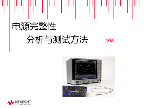
探头负载对被测电路的影响
PN7020A—50kΩ @ DC
50Ω cable to oscilloscope (50Ω @ DC) DCVrms= 3.31V
50Ω @ DC pulled this supply down ~60mV (changed the target this much)
DCVrms= 3.25V
不同带宽测量到的纹波噪声
N2870A 35 MHz, 1:1
N7020A 2 GHz, 1.1:1
根据需要进行灵活带宽限制
BW: 2.5 GHz Captures high-freq transients
BW: 20 MHz Attenuates high-freq transients
对电源噪声进行直方图统计和频谱分析
开关特性
功率/能量损耗 调制分析 dI/dt, dV/dt 分析 SOA安全工作区
DSOX3000/4000/6000开关电源测量选件
测量参数
输入端分析
电源质量: 有功功率, 无功功率, 视在功率, 相位 角, 功率因素, 波峰因子
3000X/4000X/6000X示波器
优点:低成本,低衰减
比。
缺点:一致性不好;隔
直电容参数及带宽不好 控制;纹波测量和电压 测量不能同时进行。
Partner Logo Here
N7020A高带宽、低噪声探头
N7020A高带宽低噪声探头: 高达2GHz带宽 低噪声,衰减比仅为1.1:1
高达+/- 24V的偏置范围 高输入阻抗:50 KΩ @ DC
为使DC-DC 变换器能对大规模集成电路的负载变化作出快速响应,降 低由于较大负载电流的变化造成的供电电压的瞬时波动,验证PDN网 络的阻抗是否被限制在极低范围内是非常必要的。
安捷伦程控待机电流测试步骤

待机电流测试步骤
测试项目:
待机电流
A: 屏灭时候待机平均电流和最小电流。
B: 屏亮时候待机平均电流和最小电流。
多媒体
屏灭时最大音量播放MP3时候平均和最小电流。
通话时
屏灭时正常通话中的平均电话与最小电流
测试的结果保留4个有效数字.另外,因为自动测试出来的电流有可能为0,所以最小电流用目测,也就是等手机稳定下来之后,眼睛看到的最小电流____基底电流.
正常范围电流值:
有SIM卡待机电流:基底电流1.5mA, 平均电流6mA 左右
无SIM卡待机电流:基底电流1.5mA, 平均电流6mA 左右
屏亮时:130mA
多媒体测试电流:250mA左右
正常通话电流:正常150mA左右
测试步骤:
1.打开稳压电源,首先调整电源的输出电压,
设置初始值:Output on/off
输入电压值:V oltage → Enter Number → 4 → Enter
输入最大电流值:Current → Enter Number → 2 → Enter
2.取出手机电池,插入下载线并接好电源,测待机电流时,须等手机开机后处于稳定状态后开始测试,大概一分钟左右。
3.打开电脑上的电流测试表格,点击工具栏
中的弹出
选择Current avg. Current max .Current min三项,再选择Properties
弹出
设置为每隔1s测试一次,总测试100次,按确定开始测试待机电流。
标准电流测试结果曲线图如下所示:
4.将Current avg/Current min中所测100个数值分别求平均值,记录所得数值到电流测试表格中,并上传到服务器上。
agilent u1701b 双屏手持式电容测量仪 快速入门指南说明书

Agilent TechnologiesAgilent U1701B双屏手持式电容测量仪快速入门指南您的电容测量仪附随有以下物件:✔鳄鱼夹引线 ✔印刷版快速入门指南✔9 V 碱性电池✔校准证书如果缺少任何物品或存在已损坏的物品,请联系离您最近的 Agilent 销售处。
有关详细信息,请参阅 Agilent 网站 (/find/handheld-tools) 上的 Agilent U1701B 双屏手持式电容测量仪用户及维修指南。
为避免损坏本设备,请勿超出输入限值。
不要向输入端子施加电压。
测试前进行电容器放电。
U1701B 快速入门指南电容测量步骤:1按以开启此仪表。
1要测定电容,请保持测试引线处于开路状态,然后按,以除去仪表和引线的残余电容。
2将电容器脚分别插入 + 和 – 输入端子。
请确保电容器脚的极性正确。
3将手从电容器移开,以开始测试。
4读取显示屏上的测量值。
CAUTION 小心在测试中为避免对测量仪或设备造成损坏,请在测量电容之前,断开电路连接,并对电容器放电。
U1701B 快速入门指南特征与功能编号键功能1电源开启/关闭仪器2SET 设置对比模式的上/下限3REC 静态记录模式4对比模式5TOL 容差模式6REL 相对模式7HOLD SAVE 数据保持将设置值存储到存储器中8RANGE AUTO 手动选择范围自动选择范围9HI/LO上/下限背光显示屏854123976U1701B 快速入门指南如何进入设置模式按住以将仪器从 OFF 状态开启。
听到蜂鸣声时释放 ,仪器随后将进入设置模式。
即使在仪器关闭之后,这些参数也将保留在非易失性存储器中。
要在设置模式下配置相关参数,请确保遵循下列步骤:1按 (向左键)或 (向右键)选择要设置的菜单项。
2按(向上键)或(向下键)更改参数。
3按选择要调整的数字,选定的数字将会闪烁。
4按住 1秒钟以上以保存设置。
5按住1 秒钟以上以退出设置模式。
特征与功能操作步骤开启或关闭电源按 启用数据保持功能按 触发保持下一读取数即刻按退出数据保持模式按住 1 秒钟以上启用记录功能•当记录了一个新的 MAX 或 MIN 值时,蜂鸣器将发出蜂鸣声。
安捷伦示波器探头

安捷伦示波器探头为获得示波器的最高使用效能,您应按特定的应用需要选用恰当的探头和附件。
这正是安捷伦公司为5000、6000 和7000 系列InfiniiVision示波器提供创新的全系列探头和附件的原因。
如欲了解有关安捷伦附件最新和最全面的信息,请访问我们的网站: http://.cn/find/scope_probesAgilent 5000InfiniiVision 示波器探头与附件、6000 和7000 系列选型指南技术资料目录探头兼容性表 (2)无源探头................................................................................................................................ .. 3高压无源探头......................................................................................................................... 5InfiniiMax 有源探头和附件 ................................................................................................. 6高压差分有源探头............................................................................................................... 8单端有源探头.. (10)混合信号示波器逻辑探头................................................................................................. 14电流探头................................................................................................................................. 16楔形探头适配器................................................................................................................... 18PC 连通性................................................................................................................................19Agilent IntuiLink 软件...................................................................................................... 19其他附件........................................................................................................................... 20测试车............................................................................................................................... 20仪器箱............................................................................................................................... 20机架安装套件 ................................................................................................................. 19探头定位器...................................................................................................................... 21安捷伦优势服务............................................................................................................. 封底安捷伦联系方式 ............................................................................................................. 封底探头兼容性表如欲得到更换探头或探头附件的订货信息: 请按照您的探头型号直接到表中列出的页数查看详细内容。
安捷伦数字万用表34420A技术资料
低功率电阻 5
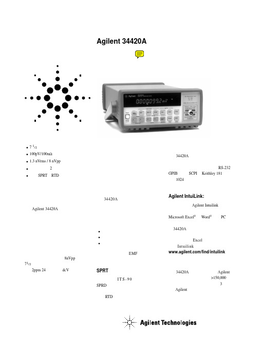
1.0000000Ω 10.000000Ω 100.00000Ω 1.0000000kΩ 10.000000kΩ 100.00000kΩ 1.0000000MΩ
10mA 10mA 1mA 100µA 10µA 5µA 5µA
0.0015+.0002 0.0015+.0002 0.0015+.0002 0.0015+.0002 0.0015+.0004 0.0015+.0012 0.0伏级的性能
Agilent 34420A 纳伏 / 微欧表是适 用于进行低电平测量的高灵敏多用表。 它把低噪声电压测量与电阻和温度功能 结合在一起,建立了灵活的低电平测量 和高性能的新标准。
去掉低电平测量的不确定性
34420A 把低噪声纳伏输入与高稳 定度电流源相组合,以提供精密的低电 平电阻测量 ── 从而避免了外电流源 的成本和复杂性。所包括的三种电阻模 式为:
LO 引线电阻,10Ω 量程限制为 10.5Ω,100Ω 量程限制为 105Ω。 7 对于 25Ω SPRT,在最后 4 小时内用水的三相点检查。未经水三相点检查时,24 小时
指标增加 0.0130C,90 天指标增加 0.0350C,1 年指标增加 0.550C。 8 对于固定的参考结,外参考结增加 0.30C,内参考结增加 2.00C。 9 在 2 小时预热后,6.5 位(10 PLC),模拟滤波器关,数字滤波器为中(50 读数平均)。
系统速度 6
配置速率:
26/s 至 50/s
自动速率(电压):
> 30/s
ASCII 读数至 RS-232: 55/s
ASCII 读数至 GPIB: 250/s
最大内触发速率:
如何选择正确的电流探头
是德科技如何选择正确的电流探头应用指南概述示波器电流探头让示波器能够测量电流,扩展了测量电压以外的用途。
基本上而言,电流探头通过导体感应电流流动,并将电流转化为探头可以在示波器上查看并测量的电压。
最常用的电流测量方式是对带电导体的磁场感应。
然而,还有多种可以选择的电流探头类型,且每种探头都有最佳应用领域。
当正确用于设计的应用情况时,可以获得最佳的结果。
本应用指南介绍常见的电流探头解决方案类型、基本原理、每种电流探头类型的优势和局限性,以及将电流探头用于示波器应用时的实际考虑因素,从而充分利用这些探头。
电流探头类型电流探头广泛用于功率设备或电源电流测量,它们已经成为使用示波器进行精确的电流测量不可或缺的工具。
为了满足电流测量需求,有很多不同的技术可用来测量电流,但最常见的配合示波器使用的方法有:1. 检测电阻或分流器:基于欧姆定律2. 夹合式电流探头 - 交流电流互感器或混合霍尔效应传感器/交流电流互感器3. 罗氏线圈:用于大交流电流测量的便捷探头检测电阻或分流器测量 DUT 电流的一种直接方式是在电流中使用分流电阻,测量电阻两端的压降,并使用欧姆定律方程式(即,I = V/R)将电压转换为电流。
此方法是有创测定法,其中检测/分流电阻和电压测量电路或探头通过电气连接,并且是待测设备的一部分。
因此,有很多因素需要考虑。
选择检测电阻电阻值、精度、温度系数和物理尺寸的选择均取决于待测量的电流量及其特征。
电阻值越大,SNR 越大,测量精度也越高。
但是,较大的电阻值将导致电阻上功耗的增加,从而产生不需要的电压骤降,其也被称为负担电压。
在负担电压损失以外,还存在检测电阻值和测量噪声、灵敏度和带宽之间的权衡。
为了降低负担电压的影响,用户可能需要尽可能使用最小的检测电阻值,但较低的检测电阻会对测量产生不利影响。
较大的检测电阻值意味着检测电阻上压力骤降的增加,以及负载的低电压,从而引起系统性能和效率问题。
这是一项需要平衡的操作。
简单记录器AmpFlex电流探头用户手册说明书
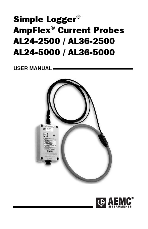
Simple Logger®AmpFlex® Current Probes AL24-2500 / AL36-2500 AL24-5000 / AL36-5000 USER MANUALTable of ContentsWarning (3)International Electrical Symbols (3)Receiving Your Shipment (4)Packaging (4)Specifications (4)Features (6)Indicators and Buttons (6)Inputs and Outputs (6)Range Selection (6)Battery Installation (7)Operation (7)Software (8)Minimum Computer Requirements (8)Installation (8)Using the Software (9)Cleaning (9)Repair and Calibration (10)Technical Assistance and Sales (10)Limited Warranty (10)Warranty Repairs (10)Simple Logger® AmpFlex® Current ProbesInternational Electrical SymbolsThis symbol signifies that the loggers are protected by double orreinforced insulation. Use only specified replacement parts whenservicing the instrument.This symbol signifies CAUTION! and requests that the user referto the user manual before using the instrument.Simple Logger® AmpFlex® Current ProbesReceiving Your ShipmentUpon receiving your shipment, make sure that the contents are consistent with the packing list. Notify your distributor of any missing items. If the equipment appears to be damaged, file a claim immediately with the carrier and notify your distributor at once, giving a detailed description of any damage.PackagingThe AmpFlex® Current Probes include the following:•User manual•One 9V battery• 6 ft RS-232 cableSpecificationsELECTRICALNumber of Channels: 1Current Ranges: 2Input: AL24/36-2500 - 250/2500 Arms (internally selectable)AL24/36-5000 - 500/5000 Arms (internally selectable)Input Connection: Permanent Flexible Sensor*Accuracy: <12.5% of Scale 1% of Reading + 2 x Resolution>12.5% of Scale 1% of Reading + ResolutionResolution:AL24/36-2500: 250 Arms AL24/36-2500: 2500 ArmsScale Range Maximum Input Resolution Scale Range Maximum Input Resolution 100% 250 Arms 1 Arms 100% 2500 Arms 10 Arms50% 125 Arms 0.5 Arms 50% 1250 Arms 5 ArmsArmsArms2.525% 62.5 Arms 0.25 Arms25%62512.5% 31.25 Arms 0.125 Arms 12.5% 312.5 Arms 1.25 ArmsAL24/36-5000: 500 Arms AL24/36-5000: 5000 ArmsScale Range Maximum Input Resolution Scale Range Maximum Input Resolution 100% 500 Arms 2 Arms 100% 5000 Arms 20 Arms50% 250 Arms 1 Arms 50% 2500 Arms 10 Arms25% 125 Arms 0.5 Arms 25% 1250 Arms 5 ArmsArms12.5% 62.5 Arms 0.25 Arms 12.5%625Arms 2.5Simple Logger® AmpFlex® Current ProbesSample Rate: 4096/hr max.Data Storage: 8192 readingsData Storage Technique: (TXR™) Time Extension Recording™Power: 9V Alkaline NEDA 1604, 6JF22, 6LR61Battery Life Recording: 6 months continuous recording @ 25°C Output: RS-232 via 5-pin circular connector; 1200 BpsINDICATORSOperation Mode Indicator: One Red LED∙Single Blink: STANDBY mode∙Double Blink: RECORD mode∙No Blinks: OFF mode∙Continuously On: Overload conditionCONTROLSOperation Mode: Push Button, Internal Range: Slide SwitchENVIRONMENTALOperating Temperature: -4 to +158°F (-20 to +70°C)Storage Temperature: -4 to +174°F (-20 to +80°C)Relative Humidity: 5 to 95% non-condensingMECHANICALSize: 2-1/2 x 1-9/16 x 4-1/2” (63.5 x 40.64 x 114.3mm)Maximum Conductor Size: 24" length: 8" Ø; 36" length: 12" ØCase: Weatherproof NEMA4X, IP65 ratedSAFETY Working Voltage: IEC 1010-1, 600V, CAT IIIORDERING INFORMATIONSimple Logger® AmpFlex® Model AL24-2500 .................... Cat. #2113.72 Simple Logger® AmpFlex® Model AL36-2500 .................... Cat. #2113.73 Simple Logger® AmpFlex® Model AL24-5000 .................... Cat. #2113.74 Simple Logger® AmpFlex® Model AL36-5000 .................... Cat. #2113.75 *Reference condition: 23︒C ± 3K, 20 to 75% RH, Frequency 45-3000Hz, No AC external magnetic field, DC magnetic field ≤ 40A/m, centered conductor, battery voltage 9V ± 10%.Simple Logger® AmpFlex® Current ProbesFeatures(1)Start/Stop Button(2)Flexible Sensor Input(3)Operation Mode Indicator(4)RS-232InterfaceIndicators and ButtonsThe AmpFlex® Logger has only one button and one indicator. Both are located on the front panel.The button is used to start and stop recordings and to turn the logger on and off. The red LED indicates the status of the logger; OFF, STANDBY or RECORDING. When the LED is lit continuously, it indicates an overload condition.Inputs and OutputsThe top of the logger incorporates a Array permanent flexible sensor attachedby a 5 ft lead.The bottom has a 5-pin circularconnector used for serial datatransmission from the logger to yourcomputer.Range SelectionBefore operating, determine themaximum current to be logged.Remove the back cover and selectthe appropriate range as shown.Simple Logger® AmpFlex® Current ProbesBattery InstallationUnder normal conditions, the battery will last up to 6 months of continuous recording unless the logger is restarted very frequently.In the OFF mode, the logger puts almost no load on the battery. Use the OFF mode when the logger is not in use. Replace the battery every six months in normal use.If the logger will be used at temperatures below 32°F (0°C) or is frequently turned on and off, replace the battery every three to four months.1.Make sure your logger is turned off (no light blinking) and allinputs are disconnected.2.Turn the logger upside down. Remove the four Phillips headscrews from the base plate, then take off the base plate.3.Locate the two-wire (red/black) battery connector and attach the9V battery to it. Make sure that you observe polarity by lining upthe battery posts to the proper terminals on the connector.4.Once the connector is plugged onto the battery, insert the batteryinto the holding clip on the circuit board.5.If the unit is not in record mode after installing the new battery,disconnect it and press the button twice then reinstall the battery.6.Reattach the base plate using the four screws removed in steptwo.Your logger is now recording (LED blinking). Press the test button for 5 seconds to stop the instrument.Note: For long-term storage, remove the battery to prevent discharge effects.OperationPosition the AmpFlex® sensor around the conductor to be measured. Be sure that the positioning of the logger sensor does not violate the minimum allowable bending radius of 0.75 inches (19mm).Next, press the start/stop button on the front of the unit to begin the recording session. The indicator light will double blink to indicate that the recording session has started. When the recording session has been completed, press the start/stop button to end the recording. The indicator light will single blink to indicate that the recording session has ended and the unit is in stand-by. Remove the logger from the conductor and transport it to the computer for data downloading. See the User Guide for downloading instructions.Simple Logger® AmpFlex® Current ProbesSOFTWAREMINIMUM COMPUTER REQUIREMENTSProcessor: 486 or higherRAM Storage: 8MBHard Drive Space: 8MB for application, approx. 400K for each storedfile Environment: Windows®7, 8, 8.1, 10Port Access: (1) 9-pin serial port and (1) parallel port for printer support INSTALLATIONYour Simple Logger® software is supplied on a USB drive. To install the program, perform the following steps:Auto Run Disabled: If Auto Run is disabled, insert the Simple Logger®drive into the USB slot, then select Run from the Start Menu. In the dialog box that appears, type: D:\setup, then click the OK button. NOTE: In this example, your drive is assumed to be drive letter D.If this is not the case, substitute the appropriate drive letter.Auto Run Enabled: If Auto Run is enabled, insert the Simple Logger®drive into the USB slot and follow the on-screen prompts to complete the setup.•Select Simple Logger 6.xx•Select Acrobat Reader to install Adobe Reader•Select Explore Drive to view the User Guide, Simple Logger® Catalog or user specific manuals in PDF format.To view the documents included on the drive, you must have Acrobat Reader installed on your machine. If you do not have it installed, you can install it from the Simple Logger® Software drive. Installing Acrobat Reader: Select Run from the Start Menu. In the dialog box that appears, type: D:\Acrobat\setup, then click OK.NOTE: In this example, your drive is assumed to be drive letter D.If this is not the case, substitute the appropriate drive letter.Simple Logger® AmpFlex® Current ProbesUSING THE SOFTWARELaunch the software and connect the RS-232 cable from your computer to the logger.Note: The first time the program is launched you will need to select a language.Select “Port” from the menu bar and select the Com port you will be using (see your computer manual). Once the software automatically detects the baud rate, the logger will communicate with the computer. (ID number of the logger and number of points recorded displayed). Depending on the selected range, “ALXX-2500” or “ALXX-250” will be displayed and automatically scale the graph accordingly.CleaningThe body of the logger should be cleaned with a cloth moistened with soapy water. Rinse with a cloth moistened with clean water. Do not use solvent.Simple Logger ® AmpFlex ® Current Probes10Repair and CalibrationTo ensure that your instrument meets factory specifications, we recommend that it be submitted to our factory Service Center at one-year intervals for recalibration, or as required by other standards or internal procedures.For instrument repair and calibration:Contact our Service Center for a Customer Service Authorization number (CSA#). This will ensure that when your instrument arrives, it will be tracked and processed promptly. Please write the CSA# on the outside of the shipping container. If the instrument is returned for calibration, we need to know if you want a standard calibration, or a calibration traceable to N.I.S.T. (includes calibration certificate plus recorded calibration data).Chauvin Arnoux ®, Inc. • d.b.a. AEMC ® Instruments15 Faraday Drive • Dover, NH 03820 USATel: (800) 945-2362 (Ext. 360) • (603) 749-6434 (Ext. 360)Fax: (603) 742-2346 or (603) 749-6309***************•(orcontactyourauthorizeddistributor)Costs for repair, standard calibration, and calibration traceable to N.I.S.T. are available. NOTE: All customers must obtain a CSA# before returning any instrument.Technical and Sales AssistanceIf you are experiencing any technical problems, or require any assistance with the proper operation or application of your instrument, please call or e-mail our support hotline: Phone:(800)343-1391•(508)698-2115•********************• NOTE: Do not ship instruments to our Foxborough, MA address.Limited WarrantyThe AmpFlex ® Current Probes are warranted to the owner for a period of two year s from the date of original purchase against defects in manufacture. This limited warranty is given by AEMC ® Instruments, not by the distributor from whom it was purchased. This warranty is void if the unit has been tampered with, abused or if the defect is related to service not performed by AEMC ® Instruments. For full and detailed warranty coverage, read the Warranty Coverage Information, available at .What AEMC ® Instruments will do: If a malfunction occurs within the warranty period, you may return the instrument to us for repair, provided we have your warranty registration information on file or a proof of purchase. AEMC ® Instruments will, at its option, repair or replace the faulty material.Warranty RepairsWhat you must do to return an Instrument for Warranty Repair:First, request a Customer Service Authorization Number (CSA#) from our Service Department, then return the instrument along with the signed CSA Form. Write the CSA# on the outside of the shipping container. Return the instrument to:Chauvin Arnoux ®, Inc. d.b.a. AEMC ® InstrumentsService Department15 Faraday Drive • Dover, NH 03820 USATel: (800) 945-2362 (Ext. 360) • (603) 749-6434 (Ext. 360)Fax: (603) 742-2346 or (603) 749-6309***************Caution: To protect yourself against in-transit loss, insure your returned material.NOTE: All customers must obtain a CSA# before returning any instrument.Chauvin Arnoux®, Inc. d.b.a AEMC® Instruments15 Faraday Drive • Dover, NH 0382099-MAN 100208 v14 09/18。
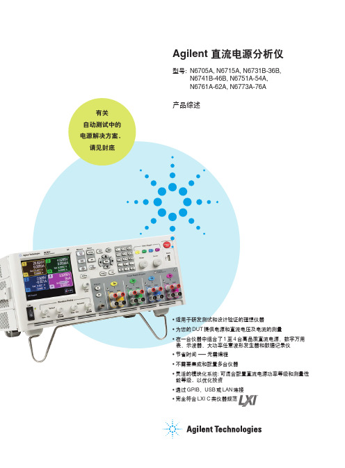
N6705A 直流电源分析仪
7
其它特性
可设置电压变化率
提高测量精度的 4 线远端感应
图10. Output On/Off Delays 屏幕允许您送 入各输出的延迟时间。设置的图形显示确 认您的选择无误。
6
大功率任意波形发生器
Agilent N6705A 直流电源分析 仪中的各直流电源模块都有内置的 任意波形发生器调制功能。因此可 把该直流输出当作直流偏置瞬态发 生器,或是大功率任意波形功率发 生器。最大带宽由模块的类型确 定。见 21 页表中列出的各种直流 电源模块类型的带宽。
Agilent N6705A 使用运行长度 编码,波形中的每一点由电压设置 和停留时间或逗留于该设置的持续 时间定义。可通过只规定少量的点 数产生波形。例如只需3 个点就可 定义脉冲。
隔,它可设置为 75ms 至 60s。对 于每路直流输出,数据记录仪可 同时或分别记录电压测量和电流 测量结果。所有直流模块类型都 可使用标准模式数据记录。
• 连续采样模式: 直流电源模块中的 内置数字化仪以 50kSa/s 读出速 率连续运行。您可规定采样周期, 即要累积连续读数的时间周期。 每一采样周期将保存一个平均读 数(也可选最小值和最大值)。在 该模式时,数字化仪连续运行,
对于用户定义的电压和电流波 形,您可下载多达 512 个电压或电 流设置点。为各设置点规定停留时 间,输出将在该设置点保持(或停 留)所编程的停留时间值。对于用 户定义波形中 512 个设置点的每一 设置点,您可有分辨率为 1μs,从 0s 至 262s 的不同停留时间*。模块 将按用户定义的量值表步进,在各 设置点停留设置的停留时间,然后 移到下一设置点。用户定义波形可 从 CSV 文件输入,或直接从直流 电源分析仪的前面板送入。
Agilent 34330A 电流电流分流器说明书
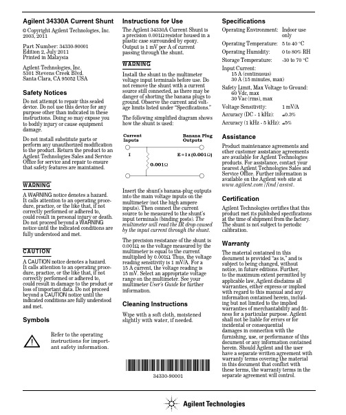
Agilent 34330A Current Shunt© Copyright Agilent Technologies, Inc.2003, 2011Part Number: 34330-90001Edition 2, July 2011Printed in Malaysia Agilent Technologies, Inc.5301 Stevens Creek Blvd.Santa Clara, CA 95052 USASafety NoticesDo not attempt to repair this sealed device. Do not use this device for any purpose other than indicated in these instructions. Doing so may expose you to bodily injury or cause equipment damage.Do not install substitute parts orperform any unauthorized modification to the product. Return the product to an Agilent Technologies Sales and Service Office for service and repair to ensure that safety features are maintained.WARNINGIt calls attention to an operating proce-dure, practice, or the like that, if not correctly performed or adhered to,could result in personal injury or death. Do not proceed beyond a WARNING notice until the indicated conditions are fully understood and met.C A U TI ONIt calls attention to an operating proce-dure, practice, or the like that, if not correctly performed or adhered to,could result in damage to the product or loss of important data. Do not proceed beyond a CAUTION notice until the indicated conditions are fully understood and met.SymbolsInstructions for UseThe Agilent 34330A Current Shunt is a precision 0.001Ω resistor housed in a plastic case surrounded by epoxy. Output is 1 mV per A of current passing through the shunt. WARN IN Gvoltage input terminals before use. Do not remove the shunt with a current source still connected, as there may be danger of shorting the banana plugs to ground. Observe the current and volt-age limits listed under “Specifications.” The following simplified diagram shows how the shunt is used:Insert the shunt’s banana-plug outputs into the main voltage inputs on the multimeter (not the high ampere inputs). Then connect the current source to be measured to the shunt’s input terminals (binding posts). The multimeter will read the IR drop caused by the input current through the shunt.The precision resistance of the shunt is 0.001Ω, so the voltage measured by the multimeter is equal to the currentmultiplied by 0.001Ω. Thus, the voltage reading sensitivity is 1 mV/A. For a 15 A current, the voltage reading is 15 mV. Select an appropriate voltage range on the multimeter. See your multimeter User’s Guidefor further information.Cleaning InstructionsWipe with a soft cloth, moistened slightly with water, if needed.*34330-90001*34330-90001SpecificationsOperating Environment:Indoor useonly Operating Temperature: 5 to 40 °C Operating Humidity:0 to 80% RH Storage Temperature:-30 to 70 °CInput Current:15 A (continuous)30 A (15 minutes, max)Safety Limit, Max Voltage to Ground: 60 Vdc, max30 Vac (rms), max Voltage Sensitivity: 1 mV/A Accuracy (DC - 1 kHz):±0.3%Accuracy (1 kHz - 5 kHz):±5%AssistanceProduct maintenance agreements and other customer assistance agreements are available for Agilent Technologies products. For assistance, contact your nearest Agilent Technologies Sales and Service Office. Further information is available on the Agilent web site at /find/assist .CertificationAgilent Technologies certifies that this product met its published specificationsat the time of shipment from the factory. The shunt is not subject to periodic calibration.WarrantyThe material contained in thisdocument is provided “as is,” and is subject to being changed, without notice, in future editions. Further, to the maximum extent permitted by applicable law, Agilent disclaims all warranties, either express or implied with regard to this manual and any information contained herein, includ-ing but not limited to the implied warranties of merchantability and fit-ness for a particular purpose. Agilent shall not be liable for errors or for incidental or consequentialdamages in connection with thefurnishing, use, or performance of this document or any information contained herein. Should Agilent and the user have a separate written agreement with warranty terms covering the material in this document that conflict with these terms, the warranty terms in the separate agreement will control.instructions for import-Refer to the operatingant safety information.。
AMU_PH

警。 • 两路干结点可编程为限位开关或 PID 控
制。 • 干结点输入可冻结测量值或中断自动控制。
Transmitter AMU pH-Redox
Transmitter AMU pH-Redox
Data sheet No. DenA11431X0X
pH / ORP Measurement
信号输入电流隔离. 输入阻抗:
> 1013 Ω
Electrical Connection Scheme
pH 测量 测量范围: 分辨率: 参比温度:
0.00 -- 14.00 pH 0.01 pH 25 °C
电源 电压:
功耗:
85 - 265 VAC, 47 - 63 Hz 或 24 VDC, ± 15 % max. 20 VA
操作 仪表分为“Messages”、 “Diagnostics”、 “Maintenance”、 “Operation”和 “Installation”四个主菜单,操作简单。
用户菜单可有英文、德文、法文和西班 牙文四种选择。
CN-A83 . 228 . 027
附件: Swagelok 连接卡套是不包括在标准配置中的,请根据实际需要订购: A-86.530.020 Swagelok ¼" NPT 母螺纹连接¼"管 (∅ 6.35 mm),直管 A-86.530.020 Swagelok ¼" NPT 母螺纹连接¼"管 (∅ 6.35 mm),弯管 A-86.530.040 Swagelok ¼" NPT 母螺纹连接 10 mm 管 A-86.530.050 Swagelok ¼" NPT 母螺纹连接 8 mm 管
AEMC Instruments FLEXPROBE 灵活电流探头模型 24-3001 说明书
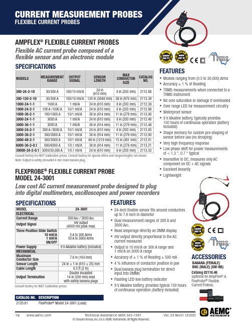
AMPFLEX ® FLEXIBLE CURRENT PROBESFlexible AC current probe composed of a flexible sensor and an electronic module FLEXPROBE ® FLEXIBLE CURRENT PROBE MODEL 24-3001Low cost AC current measurement probe designed to plug into digital multimeters, oscilloscopes and power recorders FEATURES• Models ranging from (0.5 to 30,000) Arms • Accuracy ± 1 % of Reading• TRMS measurements when connected to a TRMS instrument• No core saturation or damage if o verloaded • Over range LED for measurement c ircuitry • Waterproof sensor• 9 V Alkaline battery, typically provides 150 hours of continuous operation (battery included)• Shape memory for custom pre-shaping of sensor before use (no drooping)• Very high frequency response • Low phase shift for power m easurements of < 1.3 °, 0.7 ° typical• Insensitive to DC, measures only AC component on DC + AC signals • Excellent linearity • LightweightNote: Output is safety shrouded 4 mm male banana plug.Consult factory for NIST Calibration pricesFEATURES• 24-inch flexible sensor fits around conductors up to 7.6 inch in diameter• Dual measurement ranges of 300 A and 3000 A ac .• Read amperage d irectly on DMM d isplay • mV output directly p roportional to the AC current measured• Output is 10 mV/A on 300 A range and 1 mV/A on 3000 A range• Accuracy of ± 1 % of Reading ± 500 mA • 4 % influence of c onductor position in jaw • Dual banana plug t ermination for direct input into DMMs• Flashing LED low battery i ndicator• 9 V Alkaline battery, provides typical 150 hours of continuous operation (battery included)ACCESSORIESBANANA (FEMALE) BNC (MALE) (XM-BB) Catalog #2118.46(optional for AmpFlex ® & FlexProbe ® Flexible Current Probes)CATALOG NO.DESCRIPTION ®CURRENT MEASUREMENT PROBES GENERAL PURPOSE PROBES SELECTION CHARTCURRENT MEASUREMENT PROBES GENERAL PURPOSE PROBES SELECTION CHARTOSCILLOSCOPE & BNC TERMINATED PROBESNote: Consult factory for NIST Calibration priceMN261MN251TMN379TMH60MR417MR527*Phase shift indicated at maximum rating. Note: All probes are rated 600 V CAT III and CE compliant. Not all models are UL approved; please consult factory. Consult factory for NIST Calibration price.。
- 1、下载文档前请自行甄别文档内容的完整性,平台不提供额外的编辑、内容补充、找答案等附加服务。
- 2、"仅部分预览"的文档,不可在线预览部分如存在完整性等问题,可反馈申请退款(可完整预览的文档不适用该条件!)。
- 3、如文档侵犯您的权益,请联系客服反馈,我们会尽快为您处理(人工客服工作时间:9:00-18:30)。
© Keysight Technologies 2000 - 2014 Keysight Technologies
Safety Notices
CAUTION. A CAUTION notice denotes a hazard. It calls attention to an operating procedure, practice, or the like that, if not correctly performed or adhered to, could result in damage to the product or loss of important data. Do not proceed beyond a CAUTION notice until the indicated conditions are fully understood and met. WARNING. A WARNING notice denotes a hazard. It calls attention to an operating procedure, practice, or the like that, if not correctly performed or adhered to, could resul t in personal injury or death. Do not proceed beyond a WARNING notice until the ind icated cond itions are fully understood and met.
Restricted Rights Legend
If software is for use in the performance of a U.S. Government prime contract or subcontract, Software is delivered and licensed as "Commercial computer software" as defined in DFAR 252.227-7014 (June 1995), or as a "commercial item" as defined in FAR 2.101(a) or as "Restricted computer software" as defined in FAR 52.227-19 (June 1987) or any equivalent agency regulation or contract clause. Use, duplication or disclosure of Software is subject to Keysight Technologies’ standard commercial license terms, and non-DOD Departments and Agencies of the U.S. Government will receive no greater than Restricted Rights as defined in FAR 52.227-19(c)(1-2) (June 1987). U.S. Government users will receive no greater than Limited Rights as defined in FAR 52.227-14 (June 1987) or DFAR 252.227-7015 (b)(2) (November 1995), as applicable in any technical data.
4
Safety
Safety
This manual provides information and warnings essential for operating this equipment in a safe manner and for maintaining it in safe operating condition. Before using this equipment, be sure to carefully read the following warnings, cautions, and notes. NOTE This equipment is designed according to IEC 61010-1 Safety Standards, and has been tested for safety prior to shipment. Incorrect measurement procedures could result in injury or death, as well as damage to the equipment. Please read this manual carefully and be sure that you understand its contents before using the equipment. The manufacturer disclaims all responsibility for any accident or injury except that resulting due to defect in its product. Only trained service personnel who are aware of the hazard involved (for example, fire and electric shock) should perform maintenance on the instrument. When maintenance can be performed without power applied, the power cord must be disconnected from the instrument. To avoid short circuits and accidents that could result in injury or death, use the 1147B only with power lines carrying 300V or less. When conductors being measured carry in excess of the safe voltage level (SELV-E) and not more than 300V, to prevent short circuits and electric shock while the core section is open, make sure that conductors to be measured are insulated with material conforming to (1) Overvoltage Category I, (2) Basic Insulation Requirements for Working Voltages of 300 V, and (3) Pollution Degree 2. Never use this sensor on bare conductors, the core and shield case are not insulated. If a bare conductor is inevitable to be measured, make sure that the power to the wire must be turned off, when opening the jaws of the probe to insert or remove the bare wire so that 300V CAT I is always satisfied. Avoid damaging the cable insulation surfaces while taking measurements. This instrument is only made for use with the Infiniium. Do not plug the probe into any interface other than the AutoProbe interface, of which Infiniium has a protective earthing with double-insulation construction.
14
3
Introduction
Introபைடு நூலகம்uction
The 1147B is a wide-band, DC to 50 MHz, active current probe. The probe features low noise and low circuit insertion loss. The intelligent interface makes the probe ideal for use with the InfiniiVision and Infiniium products using the AutoProbe interface. This unique probe interface makes current measurements as simple as those made with the active voltage probes. The 1147B has two operating regions that provide a wide, flat frequency response. In the DC to low frequency AC region, the probe operation is based on the negative feedback of the amplifier system that includes the thin film Hall element as a detector. In the high frequency region, the probe operates as a current transformer. The 1147B is ideal for acquiring high transient time signals such as those found in motor controllers, in switching power supplies, and in current amplifiers driving inductive loads. In order to use this product effectively and to ensure a long operational life, read this user’s guide carefully and retain it for future reference.
