网线测试仪完整资料(福昕阅读器打开)
LinkIQ Cable+Network Tester 网络测试仪说明书
LinkIQ™ Cable+Network TesterThe LinkIQ™ Cable+Network Tester is the testing solution to verify cable performance up to 10 Gb/s and solve network connectivity problems. LinkIQ validates cable performance using frequency-based measurements and a wire map of the cable under test. The LinkIQ also performs ping tests to verify connectivity and nearest switch diagnostics to identify key network issues and validate switch configuration - eliminating the need for another device. Additional features include Analog and Digital Toning, Port Blink, Remote Office Locators, and the ability to manage results via LinkWare™ PC.Cable Testing You TrustThe LinkIQ™ is capable of measuring lengths up to 1000 feet (305 m) and provides distance to faults such as opens, shorts, and unterminated cable. Using the remote ID allows for a complete wire map of the cable pairs which helps identify miswired and split pairs. The primary cable testing feature of LinkIQ™ is the cable performance test which qualifies the cabling bandwidth from 10BASE-T to 10GBASE-T (10 Mb/s up to 10 Gb/s). It performs these tests via frequency-based measurements. Using IEEE-standards-based measurements ensures that tested links meet performance requirements as opposed to transmission testers which only prove that the specific test devices can communicate over the link.Operators may set performance requirements from 10 Mb/s to 10 Gb/s for a simple pass/fail indication.Cable test without remote attached shows length and pairing of each wireCable test with remote attached shows remote ID number 5, length and pairing of each wire and cable performance of up to 10 Gb/sCable test with remote attached shows remote ID number 1, length and pairing of each wire and cable performance of up to 2.5 Gb/s but failed the test due to auser-set limit of 10 Gb/s performance.Network Testing You NeedAlong with the robust cable testing features, the LinkIQ™ also provides detailed information on the nearest connected switch and connectivity testing with IP ping. The LinkIQ™ negotiates with the switch to identify the advertised data rate (up to 10GBASE-T), half/full duplex identification, the switch name and IPaddress, port number, and VLAN info.Switch port test shows switch name and IP address, connected port,and VLAN along with advertised speed and duplex settings. If a ping test is configured, the target address and average response time are shown. Scrolling down shows Power over Ethernet results.The ping test verifies connectivity to devices on the local network or the internet and supports both IPv4 and v6. The LinkIQ’s address may be set up manually or through DHCP. Once set up, the ping test is run as part of the Autotest when a switch is detected. Results of the ping test include identification and responsetime of each of four pings to the target, the DNS server and gateway.Ping result screen shows response time to target for each of four pings. Scrolling down displays DHCP, DNS and gateway information.In-Depth PoE TestingWhile Power over Ethernet makes installation of devices such as security cameras and access points simpler, a survey by the Ethernet Alliance of over 800 installers, integrators and end users found that four of five respondents experienced difficulties in integrating PoE systems. Part of this can be traced to the fact that the IEEE offers three PoE standards, the term “PoE” is not registered and there are a variety of non-standards-compliant implementations as well.Switch port Power over Ethernet result shows pairs used, power and class available and results of the PoE test under load.To simplify PoE installation and troubleshooting, the LinkIQ displays the pairs where power is provided, including the different power levels and pairs for dual-signature implementations. Further, the LinkIQ will actually place a load on the connection to ensure that the advertised power is actually being delivered by the switch across the cabling infrastructure. The LinkIQ has been certified by the Ethernet Alliance to IEEE-802.3™ standards for reliable multivendor interoperability.LinkWare™ DocumentationThe LinkIQ provides complete documentation abilities for the tests it performs. Up to 1,000 results can be stored in the tester with descriptive names and recalled. Test names and numbers automatically increment as each is saved (“Annex B-1”, “Annex B-2”, “Annex B-3”, etc.) saving lots of time when testing cables in sequence.Report data may be exported to a PC for documentation purposes. The LinkIQ uses LinkWare™ PC, Fluke Networks’ reporting software which supports a variety of testers going back 20 years and is the industry’s de facto reporting solution with tens of thousands of active users. LinkWare can be used to store the results as well as generate PDF reports.Use LinkWare PC to generate PDF test reports.LIQ-100 includes LinkIQ mainframe and accessories. LinkIQ™ Feature Breakout1. RJ45 Port2. PASS/FAIL frequency-based measurement results3. Touch Screen Color Display4. Length measurement shows distance to termination, open or short5. Wiremap shows type and location of fault (miswires, split pairs, shorts, breaks)6. USB-C port for data export, software updates and charging7. Cable “Speedometer” provides bandwidth information up to 10G8. Save up to 1000 test results on the unit and export to LinkWare™ PC Ordering InformationREMOTEID-KIT Remote ID Kit (IDs #2-#7) for LinkIQ and MicroScanner PoE GLD-LIQ 1 Year Gold Support LinkIQ Cable Performance & Network Tester GLD3-LIQ 3 Year Gold Support LinkIQ Cable Performance & Network TesterPower Over Ethernet Compatibility Power Over Ethernet DiagnosticsAbout Fluke NetworksFluke Networks is the worldwide leader in certification, troubleshooting, and installation tools for professionals who install and maintain critical network cabling infrastructure. From installing the most advanced data centers to restoring service in the worst weather, our combination of legendary reliability and unmatched performance ensure jobs are done efficiently. The company’s flagship products include the innovative LinkWare™ Live, the world’s leading cloud-connected cable certification solution with over fourteen million results uploaded to date.1-800-283-5853 (US & Canada)1-425-446-5500 (International)Descriptions, information, and viability of the information contained in this document are subject to change without notice. Revised: June 6, 2023 10:01 AMLiterature ID:© Fluke Networks 2018。
TP500网络测试仪使用说明
SPLT PAIR REVERSE MISWIRE SHORT
SPLT PAIR REVERSE MISWIRE SHORT
1-2
3-6 4-5
4
7-8
Pair connected from 3-6 to 1-2 (miswire)
1-2
3-6 4-5
6
7-8
Pair connected from 4-5 to 4-5 (good)
特点
• 自动开机测试和自动关机
• 主机和远端测试仪同时快速显示测试结果
• Snap-together技术便于携带和进行跳线测试
• 音调发生功能用于音频追踪
• 调试模式
• 电量指示
音
• 测试短路、开路、错对、反接和串绕线对
产品描述
主机带有四个绿色线对指示灯, 一个绿色屏蔽 指示灯, 四个红色故障指示灯,一个红色电池低指示灯,和一个绿 色音调指示灯。远端具有四个琥珀色线对指示灯。当感应 到主机和远端的连接后,自动开始测试。主机上,四个线 对指示灯要么处于亮、灭,要么是闪烁状态。灯亮时表示 好的线对,灯灭时表示线对开路,灯闪烁表示坏的线对。 如果线对是坏的,一个或多个故障指示灯将会闪烁,显示 错误的具体类型。在远端上, 线对指示灯要么是亮,要 么是灭。灯亮表示好的线对,灯灭时表示是开路或坏的线 对。按下主机上的tone按健直到所有指示灯都亮,这样进 入调试模式。所有线对指示灯依次闪亮显示连接和错误信 息。第二次按住tone 键关闭调试模式。当不处于调试模 式时,在1.5秒内按下并释放tone键,将使TP600在所有线 对上产生一个类似鸟鸣的音频信号,闪烁的音调指示灯表 示处于音调发生状态。音调功能在三个小时后自动关闭, 或者再次按tone键手工关闭。
网络测试仪操作说明

网络测试仪操作说明指导一、测试具体条件:
网络测试仪:
测试具备组件:
二、馈线连接
三、测试设置
1、开机
开机主界面显示:
2、设备参数设置:
设置界面图:
第一步:设置起始频率值为:10M(点选界面start键,然后按选10,
和M键,起始频率设置完成。
)
设置完成屏幕显示:
第二步:直接点选设置截止频率为20M(点选stop键,然后按选20,
和M键,截止频率设置完成。
)
设置完成界面:
第三步:设置完以上两个参数后,点选界面中的Cal键
调出主菜单界面:
第四步:连接对接转接头
第五步:安装开路测试头
第六步:然后点选菜单对应按键:
会听到滴一声。
第七步:更换短路测试头
第八步:并点选按键
同样听到滴一声。
第九步:再次更换负载测试头
并点选
听到第一声后完成。
第十步:存储设置结果,点选按键
第十一步:点选Marker
第十二步:输入数字键盘,设置为13.56M
第十三步:选择Display,调出菜单
按照顺序按键,1-----2-------3-------1最后在按回1,就可以测试天线板了。
配置完成的界面:
这个值分别是:
黄色代表:阻抗
蓝色代表:相位
测试参考正确值范围是:黄色阻抗50 ,蓝色相位0,允许有正负10偏差。
网线测试内容详解
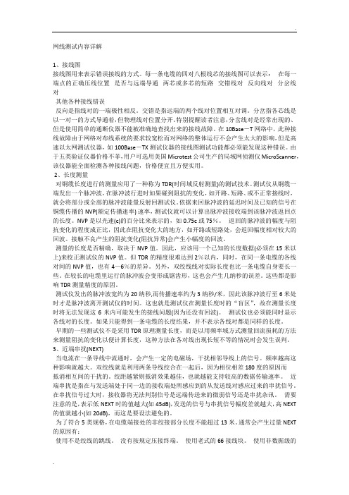
网线测试内容详解1、接线图接线图用来表示错误接线的方式。
每一条电缆的四对八根线芯的接线图可以表示:在每一端点的正确压线位置是否与远端导通两芯或多芯的短路交错线对反向线对分岔线对其他各种接线错误反向是指线对的一端极性相反。
交错是指远端的两个线对位置相互对调。
分岔指各芯线是以一对一的方式导通着,但物理线对位置分开。
特别提醒读者注意,分岔线对是经常出现的、但是使用简单的通断仪器不能被准确地查找出来的接线故障。
在10Base-T网络中,此种接线故障由于网络对布线系统的要求较宽松而对网络的整体运行不会产生太大的影响,但是高速以太网测试仪器,如100Base-TX测试仪器的接线图测试功能都必须能发现这种错误。
由于五类验证仪器价格不菲,用户可选用美国Microtest公司生产的局域网侦测仪MicroScanner,该仪器能全面检测各种接线问题,价格便宜且方便实用。
2、长度测量对铜缆长度进行的测量应用了一种称为TDR(时间域反射测量)的测试技术。
测试仪从铜缆一端发出一个脉冲波,在脉冲波行进时如果碰到阻抗的变化,如开路、短路、或不正常接线时,就会将部分或全部的脉冲波能量反射回测试仪。
依据来回脉冲波的延迟时间及已知的信号在铜缆传播的NVP(额定传播速率) 速率,测试仪就可以计算出脉冲波接收端到该脉冲波返回点的长度。
NVP是以光速(c)的百分比来表示的,如0.75c或75%。
返回的脉冲波的幅度与阻抗变化的程度成正比,因此在阻抗变化大的地方,如开路或短路处,会返回幅度相对较大的回波。
接触不良产生的阻抗变化(阻抗异常)会产生小幅度的回波。
测量的长度是否精确,取决于NVP值。
因此,应该用一个已知的长度数据(必须在15米以上)来校正测试仪的NVP值。
但TDR的精度很难达到2%以内,同时,在同一条电缆的各线对间的NVP值,也有4—6%的差异。
另外,双绞线线对实际长度也比一条电缆自身要长一些。
在较长的电缆里运行的脉冲波会变形成锯齿形,这也会产生几纳秒的误差。
测线仪使用说明
SM-8818测线(开路,短路交叉) SM-8828测线寻线SM-8838测线测长度SM-8868测线测长度寻线Cable TesterUser Manual线缆测试仪说明书警告1). 测试仪需配用9V的电池2). 测试仪15分钟以后自动关闭3). 当电池电力很低时显示屏将会有低电提示,测试仪在低电是不能正常工作的。
此系列测试仪是专门设计测试网络线、电话线、同轴电缆线的,不能用于测试其它相关线材,否则会对测试仪造成永久性毁坏。
技术规格1). 显示屏显示屏点阵128x64(有效视频范围48x32mm)2). 电源供电源是9V的叠层电池,耗电量为15 mA。
3). 低电量显示当9伏的电池量低于6.5伏时将出现低电量提示。
4). 尺寸149x 66x23 mm5). 可测试的线材STP/UTP双绞线、同轴线、电话线、USB信号线。
6). 可测试的接口端子测试仪可以测试的各种线材端口是:RJ45主端口、回环RJ45端口、BNC端口、外接BNC端口、USB (A)型端口、USB(B)型端口、RJ45远程端口、RJ11转接口。
7). 工作环境温度-10℃------+60℃.8). 双绞线长度的测量范围:1---1200 M校准精确度:2%(+/-0.5米或+/-1.5英尺)校准线长>10米测试精确度: 3%((+/-0.5米或+/-1.5英尺)(AMP, AT&T Class5 cable)显示:米,英尺,码。
9). 长度校准使用者可以用给定长度的线自我设置校准长度,校准线长度要长过10米。
10).查线序测线误检查诸如开路、短路、反接、交叉、或干扰冲突。
11).查线远端无源测试插孔(ID 1 > ID8)12).延时自动关机功能:15分钟不操作,测试仪便自动关机。
13)可测试和查找5E、6E、同轴线,USB线与电话线。
14)调节音量开关可以改变检测的灵敏度。
功能特性1).SM-88181). 在5E/6E线、同轴电缆线、USB信号线、电话线等线内查找开路、短路、跳线、反接、交叉干扰等错误。
网络测试仪使用教程

பைடு நூலகம்
网络测试仪使用方法-设备连接异常处理思路
1、海思授权失败
PAD 设备管理界面-系统-海思授权正常应显示已授权,若显示未授权则设备 的 COM 口是连接不上的,海思提供周期性授权更新,主机上网即可授权, 采用手机 USB 共享网络授权:连接一部手机-设置-移动网络-个人热点-更多网络共享-USB共享网络-打开开关-PAD上重启主机,重启完成连接后授权即可 获取,下面是依次操作流程截图;
➢ 多终端:标配6部终端,最大可支持8部终端同时测 试,同时支持NSA/SA网络测试;
➢ 多业务:支持5G数据业务FTP-DL/UL、Ping等业 务,同时支持VoNR语音/视频、EPSFB、Volte等语 音(MOS)测试;
➢ 长续航:内置4块高容量蓄电池,可连续保持6-8个 小时的测试,电池支持热插拔,可无间隙更换;
网络测试仪使用方法-设备连接异常处理思路
3、手机无参数上报
启动测试后告警提示手机无参数上报,主要检查以下项: ➢ 确认手机卡放置卡槽 1(见右图) ➢ 手机端口设置处于 Balong 模式 ➢ 手机仅充电下 ADB 调试是否打开 ➢ 手机软件重新启动下 ➢ 手机是否开机插卡---重启手机 ➢ 尝试插拔一下手机的 USB 线 ➢ 是否恢复关闭软件,删除 knowyou/cte/config/下所有文件,重
网络测试仪使用方法-设备连接异常处理思路
2、COM端口未连接
PAD 设备管理界面-手机状态显示 APP 已连接/COM 口未开启, 代表手机硬件连接正常但软件上的端口连接异常,用以下方式进行排 查: ➢ 查看海思授权是否已经授权---未授权请做授权失败操作 ➢ 检查手机开口设置---balong模式、USB 调试和仅充电下 ADB ➢ 手机 IMEI 获取是否正常---异常按照手机 APP 连接方式进行排查 ➢ 手机 SIM 卡是否放置 1 槽位,手机默认获取 1 槽位信息(见右图) ➢ 测试手机不能连接 WIFI---关闭 WIFI ➢ 手机卡是否开机插卡---重启手机
网线测线仪

电子课程设计----网线测线仪学院:电子信息工程学院专业班级:姓名:学号:指导老师:李小松2013年12月22号目录1.设计任务与要求 (3)2.总体框图 (3)3.选择器件 (4)4.功能模块 (11)5.总体设计电路图 (16)网线测线仪一.设计任务与要求设计一个 8路网线测线仪,即要求对网线内部的每一根线进行测试,是否完好。
测试通过555定时器将信号传送到计数器,再通过译码器和选择器控制灯光的依次亮灭,判断是否完好,若亮则完好,若不亮,蜂鸣器响,则表示已坏。
二.总框体图总体框图如图1所示图1 总体框图 总体框图说明:1. 发生器:用555接成的多谐振荡器,可以通过改变R 和C 的参数,改变振荡 的频率,从而获得所需的脉冲。
2. 计数器:用74LS160接成8进制计数器,完成计数功能。
因为网线是8根线, 而且需要顺序检测,所以必须有顺序和计数的要求。
3. 74LS138译码器:完成译码功能,由计数器出来的二进制代码通过译码器译 成相应的输出。
4. 74LS153选择器:完成数据选择功能,由计数器出来的二进制代码通过选择 器控制数据的输出,即根据二进制代码选择相应的输入数据,从而 输出。
5. 灯泡显示:8个灯泡构成,通过亮灭判断网线的好坏。
三. 选择器件选择器件如表1所示脉冲发生器 74LS160结成的8进制计数器74LS138译码器74LS153数据选择器指示器表1 选择器件器件数量555定时器 174LS160计数器 174LS153数据选择器 1与非门 1灯泡8电阻 2电容 2直流电源VCC 3非门10 或门 1示波器 1蜂鸣器 1显示器 1与门8 1. 555多谐振荡器555多谐振荡器电路图如图2所示图2 多谐振荡电路把555定时器接成施密特触发器后,形成振荡器。
从电路图2中可知,通过电阻R1和R2向电容C1充电,充电到Vc1=2/3VCC时,比较器1输出低电平,输出端输出低电平,放电管导通,电容通过电阻R2和放电管放电;放电到Vc1=1/3VCC时,比较器2输出低电平,输出端输出高电平,放电管截止,电容开始充电,如此循环,产生振荡。
网线测线器的使用方法

网线测线器的使用方法1.准备工作在使用网线测线器之前,需要准备好以下工具和材料:-网线测线器-网线(正常的网线和待测的网线)-显示屏或计算机2.连接测试仪将网线测线器的一个端口与计算机或显示屏相连,可以通过USB接口或者其他方式进行连接。
确保连接稳定。
3.准备工作将待测的网线的一个端口插入网线测线器的另一个端口中。
确保连接牢固。
4.启动测试按下网线测线器上的电源开关或启动按钮,启动测试仪。
测试仪会自动检测网线连接。
5.网线连接状态网线测线器会显示网线的连接状态。
通常有四个灯显示,分别代表四对线对应关系的连通情况。
如果四盏灯都亮起,表示网线连接正常;如果只有其中一两盏灯亮起,表示有一对或两对线对应关系出现问题;如果四盏灯都不亮,表示网线无法连接。
6.故障识别如果网线连接失败或出现问题,网线测线器会显示具体的故障信息。
这些信息可能包括线缆中存在断线、接触不良或线序的问题等。
7.故障排查和修复根据网线测线器提供的故障信息,可以进行故障排查和修复。
例如,如果显示线缆存在断线,需要检查网线是否损坏或连接是否牢固,必要时更换网线或调整连接。
8.测试结果分析根据网线测线器显示的测试结果,可以判断网线连接的质量和稳定性。
如果测试结果良好,表示网线连接可靠;如果测试结果较差,需要进一步检查和调整,确保网线连接正常。
需要注意的是,使用网线测线器时应遵循以下安全注意事项:-确保电源开关在使用之前处于关闭状态,以避免意外触电。
-使用过程中应注意手部和身体的安全,避免受伤。
-在测试过程中不要用力过猛,以免损坏网线测线器或网线。
网络线缆测试仪使用

网络线缆测试仪使用
1、什么是网络线缆测试仪
网络线缆测试仪包括主机和辅机,主要用于检测网络、线路远程检测与同轴电缆测试,功能较强、实用方便。
其采用的自动扫描方式,能快速进行测试,同时采用了符合人体工程学流线型外形设计,与防摔、防光设计,线条流畅简洁,更符合施工现场。
2、网络线缆测试仪的使用方法
(1)二合一多功能测试仪使用方法
①打开主机的电源开关,主机的指示灯亮起,即可自动扫描测试。
测试结果1-8按顺序跳,即说明网线导通。
②对双绞线12、3、4、5、6、7、8、G各线对逐根(对)测试,并可区别判定哪一根(对)错线,短路和开路。
(2)若接线正常,则会按下述情况显示
①若是进行网线测试,则正常情况下1-8号指示灯依次闪烁。
②若是进行电话线测试,则3-4号指示灯依次闪烁为正常情
况。
(3)若接线不正常,则会按下述情况显示
①当有一根网线如3号线短路,则主测试仪和远程测试端3号灯饰都不亮。
②当有几条线不通,则几条线都不亮,当网线少于2根线连通时,灯都不亮
③当两头网线乱序,例2、4线乱序,则显示如下:
主测试器不变:1-2-3-4-5-6-7-8-G
远程测试端为:1-4-3-2-5-6-7-8-G
④当网线有2根短路时,则主测试器显示不亮,而远程测试端显示短路的两根线灯都微亮,若有3根以上(含3根)短路时,则所有短路的几条线号的灯都不亮。
网线检测仪使用方法 检测仪维护和修理保养

网线检测仪使用方法检测仪维护和修理保养网线检测仪/网线测定仪型号:HAD—SML—8828产品介绍:对线功能,串扰测试,寻线功能,判开路点1. 用M—S和M—R两种方法测试5E/6E网线、线、BNC电缆、USB信号线的开路、短路、跳线、反接、交叉、配对等连接情况,且直观地在LCD上显示出来。
2. 对网线进行串扰测试,解决网速慢的潜在故障。
3.可以在浩繁网线、线及其它各种金属线中通过音量大小的提示在远端识别测出要查找的线,寻线长可达3000米以上具有抗干扰和高灵敏度,接收器上音量调整旋扭可以调整灵敏度大小。
4.判开路点,能精准判定网线的水晶头开路在某一端点(左,右或中心)5. 有自动延时关机功能。
6. 电压过低时有低电压显示功能。
7. 有自检与自动调整各种测试情形的功能,对电池容量与四周温度变化的自动补充功能。
测试电缆种类:8P8C:UTP双绞网络线缆;E6P6C线;USB信号线;F(S)TP BNC同轴线.LCD显示屏特点:点阵式128x64 尺寸:48x32mm单位:米(METER)、英尺(FEET)、码(YARDS)测试电缆zui大长度: 1200m精准率:2% (0.5m或1.5ft)电源规格:DC 9V电池耗电:工作电流15mA体积:1496623mm 净重:200g包装:吸塑+彩盒重量:650g/pc工作温度/湿度:0℃-50℃/20%—70%8368系列数字液晶显示网络电缆测试器是本公司经过多年的研发与测试、拥有自主的学问产权、多项的产品。
产品性能国际同类产品水平,具有低功耗、环保、率等特点。
接受一般AAA电池,插入电缆自动测试,支持单机测试、双机同步显示测试、提率。
时尚、快捷、坚固的外观设计。
一、单机测试:打开电源开关,将双绞线两头分别插入本机M、L插座,测试仪LCD屏显示TEST(ING),自动进行测试。
LCD屏数字不跳时,显示的结果为电缆连接的情况。
二、双机使用方法:用两台相同的机器,按“MODE”键2秒以上,设定其中一台为“S(LSVE)”,另一台为“M(ASTER)”即可进行测试。
计算机网络技术专业1《01 网络测线仪器的使用0》

网线检测仪的使用
网线检测仪在使用时,按以下步骤进行操作。
一、操作步骤:
1:首先将网线检测仪的电源翻开,检查是否有电。
2:网线检测仪在测量时,先将电源开关关闭,需要将一条网线的两端,一端接入该测试仪主机的网线接口上,另一端接入测试仪副机的网线接口上。
然后将主机上的电源翻开,观看测试灯的显示状况。
接入方法如下列图:3:细心观察主机和副机两排显示灯上的数字,是否同时对称显示,假设对称显示,即代表该网线良好,假设不对称显示或个别灯不亮,就是代表网线断开或制作网线头时线芯排列错误。
二、考前须知
注意:网线插入检测仪时,要先将水晶头金属触点上的污物、锈渍处理干净,再将其插入接入口内。
三、拓展资料
网线测试仪,即络电缆测试仪,可以对双绞线1,2,3,4,5,6,7,8,G线对逐根〔对〕测试,并可区分判定哪一根〔对〕错线,短路和开路。
线缆探测仪
#61-954#61-956#61-958SureTest®线缆探测仪使用说明书目录●安全声明―――――――――――――――――――――――――3 ●简介―――――――――――――――――――――――――――4 ●仪器各部分描述•信号发射器――――――――――――――――――――5•接收器――――――――――――――――――――――6•测试线套件――――――――――――――――――――8•带电池盒的钳形感应线圈――――――――――――――9 ●工作原理•信号发生与检测――――――――――――――――――9•线路的开环与闭环―――――――――――――――――9•远程回环路径―――――――――――――――――――10 ●应用•定位断路器/熔断器(保险丝)――――――――――――12•探测导线―――――――――――――――――――――13•探测低电压信号线和数据线―――――――――――――13•查找开路点――――――――――――――――――――14•查找短路点――――――――――――――――――――15•在线束中选择导线―――――――――――――――――16•定位地下的线缆和金属管――――――――――――――17•钳形电感线圈的使用――――――――――――――――18 ●仪器电池与保险丝的更换――――――――――――――――――20 ●维护―――――――――――――――――――――――――――22 ●服务与维修――――――――――――――――――――――――22 ●技术参数―――――――――――――――――――――――――22 ●质保说明―――――――――――――――――――――――――24请首先阅读安全信息请理解并认真按照以下操作说明使用。
线缆探测器只可按说明使用,否则,其提供的防护可能被削弱。
危险警示电击伤害与电器接触可能造成电击,严重伤害或死亡。
为避免电击造成人身伤害或死亡,请按说明操作。
网络测试仪表知识
网络测试仪表知识一、概述(一)用途随着网络应用的普及和深入,网络的建设、维护和故障诊断面临着巨大挑战:网络的规模越来越大、组成网络的设备越来越复杂、在网络中运行软件系统越来越庞大、网络承载的业务越来越多等等。
通过网络测试仪表可以方便地对网络运行情况进行有效分析,可以发现潜在的故障,防患于未然,避免网络瘫痪,同时可在网络发生故障时,尽快查明,迅速解决问题,避免损失扩大。
网络测试仪表是保证网络及网络设备高性能、高可靠性和高可用率的基本手段,在网络设备研发、网络建设和发展中起着越来越来重要作用。
(二)分类与特点网络测试仪表种类比较多,根据应用范围,大体上可以分为:线缆分析仪、网络运行模拟工具、网络协议分析仪和网络测试仪等几类产品。
●线缆分析仪特点主要功能是检测线路的通断状态。
测试功能主要有电缆扫描、接线图测试、电缆走向识别、电缆电气性能测试、故障检测(错对、串绕、开/短路)等,检测的电气性能参数有衰减(Attenuation)、衰减串绕比(ACR)、近端串扰(NEXT)、特性阻抗(IMPEDENCENEXT)等。
线路介质种类繁多(三类线、五类线、单模光纤、多模光纤、铜缆等),接口类型也较多(RJ45、BNC、SC、RS232等)。
目前,电缆测分析仪中国电子科技集团41所、IXIA、FULKE、Agilent公司有产品。
●网络运行模拟工具特点该类仪器可按设定流量向被测网络发送指定大小的数据报,模拟出运行网络流量状况,再现网络真实的运行情况。
当网络出现故障时,可用来再现网络故障时的运行状况,方便查找问题之所在。
目前,网络运行模拟工具思博伦、安立等公司有产品。
●网络协议分析仪特点主要用于捕获网络上的数据帧,通常使用专用硬件或计算机网卡对网络中的数据进行捕获、查看解析数据帧,再分析这些数据,检查网络故障,及时解决问题。
主要包括数据帧捕获、过滤与触发功能、对各种协议进行解析、数据帧生成、网络监控等基本功能。
●网络测试仪特点能对网络设备、网络及网络系统提供综合测试。
LAN和A V电缆检测仪说明书

52082061 REV 1© 2019 Tempo Communications Inc.11/19PA1594LAN and A/V Cable-Check™ Tester Medidor de LAN y A/V Cable-Check™Testeur LAN et AV Cable-Check™English ..................2Español .................4Français . (6)PA1594TEMPO COMMUNICATIONS1390 Aspen Way • Vista, Ca 92081 USA • 800-642-21552DescriptionThe PA1594 LAN and A/V Cable-Check™ Tester is a small, hand-held cabletester that enables network professionals to quickly and easily verify the integrity of straight-through, twisted pair, and coaxial cables. The PA1594 can also test crossover cable.SafetySafety is essential in the use and maintenance of Tempo tools and equipment. This instruction manual and any markings on the tool provide information for avoiding hazards and unsafe practices related to the use of this tool. Observe all of the safety information provided.Purpose of this ManualThis manual is intended to familiarize all personnel with the safe operation and maintenance procedures for the Tempo Communications PA1594.Keep this manual available to all personnel. Replacement manuals are available upon request at no charge at .Features• Tests UTP (Unshielded Twisted Pair), STP (Shielded Twisted Pair), and coaxial cable.• Checks continuity and configuration of wiring with RJ45 plugs.• Tests for open circuits, shorts, miswires, reversals, and split pairs.• Shield detection tests a cable’s shield integrity.• Debug mode quickly identifies which cable pairs have a specific wiring fault.• Main unit and Remote unit allow one person to test T568A, T568B, 10Base-T, and Token Ring cables.• Main unit is powered by two 1.5 V (AAA) batteries; Remote unit does not need battery.• Low battery indication.SetupTo separate the two units, hold the Main unit in one hand and the Remote unit in the other. Slide the Remote unit up ordown.Slide the Remote unit up or down.IdentificationPair and SHIELD LEDs: 1. SHIELD/COAX LED 2. Pair 1-2 LED 3. Pair 3-6 LED 4. Pair 4-5 LED 5. Pair 7-8 LEDFault Indicator LEDs: 6. SHORT LED 7. MISWIRE LED 8. SPLIT PAIR LED 9. REVERSAL LEDOthers:10. LOW BATT LED11. Mode selector switch 12. TEST button13. BNC socket of Main unit 14. RJ45 socket of Main unit 15. RJ45 socket of Remote unit 16. BNC socket of Remote unitTypical FaultsFor straight-through cable or crossover cable tests, the tester has two operating modes: Test mode and Debug mode.In Test mode, a flashing pair of LEDs indicates that this wire pair has a fault while a fault indicator LED lights up to indicate which fault was detected. Multiple flashing pair LEDs indicate multiple pairs and/or multiple faults. In this situation, use theDebug mode to diagnose the faults in more detail. Correct the faults until the cable is verified to be correct by using the tester.Refer to the “Fault Details” section on the last page of this manual.Note: For some types of cables, so called OPEN is not an abnormal condition.Therefore, there is no OPEN indicator LED. Open can be identified as an unlit pair or shield LED when the tester shows the test result. The user should determine if a wire is present and continuous or OPEN by comparing the illuminated pair and/or shield LEDs with the expected number of wires (of the cable) that should be good.During test, if the LOW BATT LED lights up, the batteries in the Main unit are low. To avoid questionable test results, replace the batteries immediately.Do not discard this product or throw away!For recycling information, go to .All specifications are nominal and may change as design improvements occur. TempoCommunications Inc. shall not be liable for damages resulting from misapplication or misuse of its products.Cable-Check is a trademark of Tempo Communications Inc.KEEP THIS MANUALPA15943TEMPO COMMUNICATIONS1390 Aspen Way • Vista, Ca 92081 USA • 800-642-2155Testing a Straight-through CableTest Mode1. Connect the Main unit to one end of the cable to be tested and the Remote unit to the other end of this cable.2. Set the mode selector switch to the Standard position.3. Press the TEST button and then release it. The tester starts testing the cable. The five green LEDs flash one time sequentially from top to bottom, and then the tester shows the test result—flashing LED indicates this pair has a fault while fault indicator LED lights up to indicate the type of fault.4. The test lasts about 12 seconds, and then the tester turns off automatically. Press the TEST button to stop the test manually at any time. Pressing the TEST button turns the tester off.Example for Test mode: The cable fault is a SHORT on pair 1-2 and pair 3-6.After the five green LEDs flash one time sequentially from top to bottom, the tester displays the following test results simultaneously:• Pair 1-2 LED and pair 3-6 LED flash green while the SHORT LED lights red.• Pair 4-5 LED lights green indicating a good pair.• Pair 7-8 LED lights green indicating a good pair.Debug ModeThe Debug mode identifies which cable pairs have a wiring fault. The unit cycles through pairs, displaying a test result one pair at a time. A fault is indicated by simultaneously lighting a pair of LEDs and the fault indicator.1. Set the mode selector switch to the Standard position. Then press and hold the TEST button until all LEDs light; release the button.2. The pair LEDs and the fault indicator LEDs work together to identify which pair is incorrect.a. If a pair LED flashes two times in series (one short and one long) while no fault indicator LED lights, the pair is wired correctly.b. If a pair has fault(s), its pair LED will give a short flash. Then this pair LED, other pair LEDs related to this pair’s fault(s), and the fault indicator LED(s) will give a long flash simultaneously.c. If a pair LED gives only a short flash that is not followed by a long flash, this pair has an OPEN fault.3. After the Debug function cycles four times through the pairs, the tester turns off automatically. Press the TEST button to stop the test manually at any time. Pressing the TEST button turns the tester off.Example for Debug mode: The cable fault is a SHORT on pair 1-2 and pair 3-6.The Debug mode LED series will be as follows:• Pair 1-2 LED gives a short flash and then pair 1-2 LED, pair 3-6 LED, and the SHORT red LED give a long flash simultaneously.• Pair 3-6 LED gives a short flash and then pair 3-6 LED, pair 1-2 LED, and the SHORT red LED give a long flash simultaneously.• Pair 4-5 LED flashes two times in series while no fault indicator LED lights. This indicates that this pair is wired correctly.• Pair 7-8 LED flashes two times in series while no fault indicator LED lights. This indicates that this pair is wired correctly.Testing a Crossover CableThe method of testing crossover cable is almost the same as testing straight-through cable. The only difference is that the mode selector switch is in Cross Cable position to test crossover cable instead of the Standard position for straight-through cable.Refer to the “Testing a Straight-through Cable” section and set the mode selector switch to the Cross Cableposition to test crossover cable.1234567812345678Crossover Cable WiringTesting Coaxial CableNote: For coaxial cable tests, the mode selector switch can be in any function position.1. Connect one end of the coaxial cable to be tested to the BNC socket of the Main unit and the other end of the coaxial cable to the BNC socket of the Remote unit.Note: The terminators on the cable to be tested should match the BNC sockets of the tester.2. Press the TEST button and then release it. The five green LEDs of the Main unit will flash one time sequentially from top to bottom, and then the tester shows the test result:• If the SHIELD/COAX LED lights green, the coaxial cable has no fault.• If the SHIELD/COAX LED does not light, the cable is faulty.Note: Refer to “Testing Examples” on the last page of this manual for reference on how to test the continuity of RCA, BNC, and Cable TV “F” cables.Indicator Light IlluminatedResult Resistance PASS Good continuity 40-100 ΩSHORT Cable is shorted< 40 ΩOPENCable is broken, bad shield connector, or bad center conductor connection> 100 ΩSpecificationsCable Length:Minimum: 1 m (3 ft)Maximum: 300 m (900 ft)Battery: 2 x 1.5 V AAA Size:Master Unit: 96.8 x 58.2 x 32.8 mm (3.81 x 2.29 x 1.29 in)Remote Unit: 96.8 x 58.2 x 32.8 mm (3.81 x 2.29 x 1.29 in)Weight: Approximately 165 g (5.8 oz)MaintenanceBattery ReplacementWhen the LOW BATT LED lights continuously, the batteries are low and should be replaced immediately.1. Remove the screws on the back cover of the Main unit and remove the back cover.2. Replace the old batteries with new ones (observe polarity).3. Reinstall the back cover and the screws.。
- 1、下载文档前请自行甄别文档内容的完整性,平台不提供额外的编辑、内容补充、找答案等附加服务。
- 2、"仅部分预览"的文档,不可在线预览部分如存在完整性等问题,可反馈申请退款(可完整预览的文档不适用该条件!)。
- 3、如文档侵犯您的权益,请联系客服反馈,我们会尽快为您处理(人工客服工作时间:9:00-18:30)。
电子产品装配与调试任务书中职组电工电子技术技能比赛执委会2011年1010月月中国··湖北武汉中国工作任务内容:一、数字网线测试仪的装配与检测(本大项分五项,第(一)项30分,第(二)项16分,第(三)项7分,第(四)、(五)项各6分,共55分)(一)数字网线测试仪元器件检测、焊接与装配(本项分3项,第1项,10分,第2项20分,共30分)1.根据给出的《数字网线测试仪》电路图和数字网线测试仪元器件中的四位一体共阴LED数码管实物,画出LED数码管的内部连接方式。
2.产品焊接(本项目分2小项,每小项10分,共20分)根据《数字网线测试仪》电路图和《数字网线测试仪元器件清单》,从提供的元器件中选择元器件,准确地焊接在赛场提供的印刷电路板上。
要求:在印刷电路板上所焊接的元器件的焊点大小适中、光滑、圆润、干净,无毛刺;无漏、假、虚、连焊,引脚加工尺寸及成形符合工艺要求;导线长度、剥线头长度(二)数字网线测试仪电路工作正常(本项分3项,第1项5分,第2项5分,第3项5分,共15分)(1)数字网线测试仪接入8V交流电,测试U1输出电压是否正常,如果正常,按下电源开关S1,电源指示灯LED1亮,第一排数码管显示的数字(显示方式为:1234-5678)和P3插座(左网线口)的序号对应,双色二极管的标号(P5~P12)与P2插座(右网线口)序号一一对应(序号如下图所示)(2)用芯线序号正确连接的网线两端分别插入P3和P2插座RJ45,此时测试仪两排数码管上下显示数字一一对应,双色二极管都显示为绿色。
拨除网线后第二排排数码不显示,双色二极管不显示。
(3)用芯线错误连接的网线两端分别插入P3(左网线口)和P2(右网线口)插座RJ45,此时测试仪第二排数码管显示的状态可以正确判断网线的错误。
状态判断:第二排数码管显示的数字即为左网线口的序号,如果其序号与第一排不一样的说明芯线交叉连接;对应的双色二极管显示红色,序号一一对应的显示绿色。
第二排没有显示的数码管说明其芯线是断开的,对应双色二极管不显示。
(三)数据测量(本项共15分)要求:用示波器的量程范围500μs/div、2V/div,测量数字网线测试仪电路中U3STC10F08XE的“41”、“42”脚数据,并把它记录在下面的表格中。
(四)装配工艺卡片编制(本项分2项,每项各5分,共10分)根据装配工艺卡片指定的数字网线测试仪元器件,完成下面装配工艺卡片的编制。
1.请把下表《装配工艺过程卡片》中的“序号(位号)”列出的各元器件,在“以上各元器件插装顺序是:”一栏中编制插装顺序(可归类处理)。
2.根据《装配工艺过程卡片》中“图样”,在“工艺要求”中一列其中的空格里填写工艺要求。
装装配工艺过程卡片装配工艺过程卡片工序名称产品图号插件PCB20111031位号装入件及辅助材料数量工艺要求工装名称代号、名称规格镊子、剪切、电烙铁等常用装接工具0805贴片电阻10kΩ±5%10805贴片电阻200Ω±5%8IC集成块(44脚)LQFP441无连焊、无歪斜、焊点光亮,CD11电解电容1000μF/25V1按图2(e)安装,注意电容正负极性CD11电解电容470μF/25V 1晶振12.000MHz1贴底板安装程序下载连接器DB91贴底板安装网线插座RJ452贴底板安装三端集成稳压器LM78051以上元件插装顺序:二、绘画电路图和绘制元器件PCB封装图(本大项分2项,第1项5分,第2项10分,共15分)说明:选手在E盘根目录下以工位号为名建立文件夹(××为选手工位号,只取后两位),选手竞赛画出的电路图命名为Sch××.schdoc,PCB元件封装库文件为splib××.PcbLib,并存入该文件夹中。
选手如不按说明存盘,将不可能给予评分。
1.绘画电路图内容:使用Protel2004DXP软件,根据赛场提供的《网线测试仪》实物电路,准确地画出《网线测试仪》的电路图中单片机STC10F08XE的原理图2.绘制元器件PCB封装图请根据《网线测试仪》实物电路,绘制STC10F08XE的PCB封装图。
三、职业与安全意识(本大项15分)操作符合安全操作规程;工具摆放、包装物品、导线线头等的处理,符合职业岗位的要求;遵守赛场纪律,尊重赛场工作人员,爱惜赛场的设备和器材,保持工位的整洁。
1.工作过程安全2.仪器仪表操作规范安全3.工具使用安全、规范4.搭建模块安全摆放5.纪律、清洁一、LM 7805(U1)引脚说明:1脚:Vi 输入端;3脚:Vo 输出端。
《集成电路与器件介绍》2脚:GND 接地端;二、STC10F08XE (U3)引脚功能说明:30~37脚:P0口,是一个8位漏极开路的双向I/O 口;40~44脚,1~3脚:P1口,是一个具有内部上拉电阻的8位双向I/O 口;18~25脚:P2口是一个具有内部上拉电阻的8位双向I/O 口;5,7~13脚:P3口:P3口是一个具有内部上拉电阻的8位双向I/O 口;4脚:RST 复位;14~15脚:基准脉冲振荡;17,28,39,6脚:P4.0口;16脚:V SS 接地;26脚:PSEN ,程序储存允许(PSEN )输出是外部程序存储器的读选通信号;27脚:ALE/PROG ,当访问外部程序存储器或数据存储器时,ALE (地址锁存允许)输出脉冲用于锁存地址的低8位字节;29脚:EA/VPP,外部访问允许;38脚:电源,V CC。
三、74HC595引脚功能说明:15,1~7脚:Q0~7,8位数据并行输出端。
直接控制数码管的8个段。
8脚:GND,接地。
9脚:Q7’,级联输出端。
10脚:,低点平时将移位寄存器的数据清零。
11脚:SH-CP,上升沿时数据寄存器的数据移位。
下降沿移位寄存器数据不变。
12脚:ST-CP,上升沿时移位寄存器的数据进入数据存储寄存器,下降沿时存储寄存器数据不变。
当移位结束后,产生一个正脉冲,更新显示数据。
13脚:,高电平时禁止输出(高阻态)。
14脚:DS,串行数据输入端。
16脚:电源VCC。
四、U6、8、12、13ULN2803APG引脚功能说明1~8脚:信号输入脚;11~18脚:信号输出脚;9脚:GND;10脚:保护二极管公共阴极。
五、MAX232(U9)引脚功能说明:1、2、3、4、5、6脚:产生+12v和-12v两个电源7脚:T2OUT8脚:R2IN9脚:R2OUT10脚:T2IN11脚:T1IN12脚:R1OUT13脚:R1IN14脚:T1OUT15脚:GND16脚:VCC(+5v)六、四位一体数码管1122334455667788DDCCBBAATitle Number RevisionSize A3Date:2011-10-30Sheet ofFile:d:\\\\project\.SchDocDrawn By:10KR910uF/25VC7S21KR4VCCGNDRST27PC827PC101212M Y1*GNDX1X212345678P2RJ4512345678910K RP1VCCP00P01P02P03P04P05P06P0712345678910KRP2VCC P20P21P22P23P24P25P26P2712345678P3RJ45200R20200R21200R22200R23200R24200R25200R26200R27104C6GNDVCCQB 1QC 2QD 3QE 4QF 5QG 6QH 7GND8Q'H9SCLR10SCK11RCK 12G13SER 14QA 15VCC16U774LS595GNDGND104C12VCCGND VCC123456789100RP4104C15VCCQB 1QC 2QD 3QE 4QF 5QG 6QH 7GND8Q'H9SCLR10SCK11RCK 12G13SER14QA 15VCC 16U1174LS595GNDGND104C20VCCGND VCC1234567891K RP6104C23VCCQB 1QC 2QD 3QE 4QF 5QG 6QH 7GND8Q'H 9SCLR10SCK11RCK 12G13SER14QA 15VCC 16U1074LS595GNDGND104C19VCCGND VCC 1234567891K RP5104C22VCCQB 1QC 2QD 3QE 4QF 5QG 6QH 7GND8Q'H 9SCLR10SCK11RCK 12G13SER14QA 15VCC 16U574LS595GNDGND104C11VCCGND VCC123456789100RP3104C14VCCQB 1QC 2QD 3QE 4QF 5QG 6QH 7GND8Q'H9SCLR10SCK 11RCK 12G13SER14QA 15VCC 16U274LS595GND104C5VCCGND QB 1QC 2QD 3QE 4QF 5QG 6QH 7GND8Q'H9SCLR10SCK 11RCK 12G13SER 14QA 15VCC 16U474LS595GND104C9VCC GND VCCVCC 123456P4Header 3X2C1+1V+2C1-3C2+4C2-5V-67891011121314GND15VCC 16T1T2R1R2U9MAX2321234567891110J1*GNDGND104C16104C18104C17104C21VCCGNDGND104C13GNDVCC G1G2G3G4G5G6G7G8R1R2R3R4R5R6R7R8GNDEA/VP 29P2.1/A919P2.0/A818P3.3/INT19P4.017GND16P3.6/WR 12P3.7/RD 13X214X115P1.51P1.62P1.73RST 4P3.0/RXD 5INT2/P4.36P3.1/TXD 7P3.2/INT08AD0/P0037AD1/P0136AD2/P0235AD3/P0334AD4/P0433AD5/P0532AD6/P0631AD7/P0730P2.3/A1121P2.4/A1222P2.5/A1323P2.6/A1424P2.7/A1525VCC38INT3/P4.239P4.128PSEN26ALE/P 27T1/P3.511T0/P3.410P2.2/A1020T2/P1.040T2EX/P1.141P1.242P1.343P1.444U3STC89C58RD+IN11IN22IN33IN44IN55IN66IN77IN88GND 9CM10OUT811OUT712OUT613OUT514OUT415OUT316OUT217OUT118U8ULN2803IN11IN22IN33IN44IN55IN66IN77IN88GND9CM 10OUT811OUT712OUT613OUT514OUT415OUT316OUT217OUT118U6ULN2803IN11IN22IN33IN44IN55IN66IN77IN88GND9CM10OUT811OUT712OUT613OUT514OUT415OUT316OUT217OUT118U12ULN2803IN11IN22IN33IN44IN55IN66IN77IN88GND9CM10OUT811OUT712OUT613OUT514OUT415OUT316OUT217OUT118U13ULN2803E D D PC G 1H B 2H 3H F A 4H DS2E D D PC G 1H B 2H 3H F A4H DS1E D D PC G 1H B 2H 3H F A4H DS4E D D PC G 1H B 2H 3H F A4H DS32A 2B 2C 2D 2E 2F 2G 2H 2A 2B 2C 2D 2E 2F 2G 2H 3A 3B 3C 3D 3E 3F 3A 3B 3C 3D 3E 3F 1BIT 2BIT 3BIT 13BIT 14BIT 15BIT 16BIT 100R R3100R R5100R R6100R R7100R R8100R R10100R R112B 2C 2D 2E 2F 2G 2H100RR22A100R R13100R R14100R R15100R R16100R R17100R R18100R R19100R R123A3B 3C 3D 3E 3F 1BIT2BIT 3BIT 4BIT 5BIT 6BIT 7BIT 8BIT 9BIT 10BIT 11BIT12BIT 123P5123P6123P9123P10123P7123P11123P8123P12GNDGNDGND GND GND GND GNDGND D11N4007D21N4007D31N4007D41N4007C1100uF/16VC2104p12P1GNDVCC_IN C3470uF/16VIN2OUT GNDU1LM7805C4104p6vACS1*VCC_INVCCR11KLED1*GNDX1X2RST P00P01P02P03P04P05P06P07P21P22P23P24P25P26P27P20RX TX DATA SH-CP ST-CPRXTX 3G 3H 3G 3H 3G 3H 9BIT 10BIT 11BIT 12BIT13BIT 14BIT 15BIT16BIT DATA SH-CP SH-CP SH-CP SH-CP SH-CP SH-CP ST-CP ST-CP ST-CP ST-CP ST-CP ST-CP N1N2N3N4N5N6N1N2N3N4N5R1R2R3R4R5R6R7R8G1G2G3G4G5G6G7G84BIT 5BIT 6BIT 7BIT 8BIT T5Altium Limited Confidential2011-11-2Page 1。