IRM138H红外接收头说明
红外转发器使用说明书(总控版)
红外转发器使用说明书(总控版)功能介绍无线红外转发器主要包括红外学习、红外发射和无线接收模块。
转发器可以学习家电遥控器的红外信号(38K频率),通过把无线信号转换为对应的红外信号,从而实现控制家电的目的。
无线红外转发器主要配合索科特智能家居系统实现远程开关家电的目的。
本转发器只针对可红外遥控(频率38K)的家用电器。
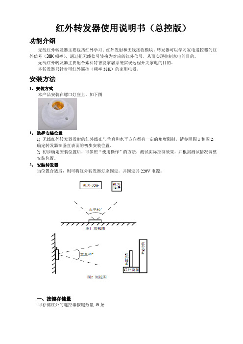
安装方法1、安装方式本产品安装在螺口灯座上。
如下图1,选择安装位置1) 无线红外转发器发射的红外线在与垂直和水平方向都有一定的角度限制。
请参照图1和图2,确定转发器在垂直表面的初步安装位置。
2) 初步确定安装位置后,可参照“使用操作”的方法,测试实际控制效果,并根据测试情况调整安装位置。
2,安装转发器当位置合适后,则可将红外转发器灯座固定。
并固定其220V电源。
一、按键存储量可存储红外的遥控器按键数量49条二、技术参数1、工作电压:AC 220±22V2、工作温度:10-40℃3、储藏温度:-10-+65℃4、工作湿度:10%-90%5、储藏湿度:10%-95%6、红外控制距离≤8m7、与家电的最大夹角:<40度8、重量:0.077Kg三、对码首次使用时,需要通过家电总控制器对红外转发器进行配置。
方法如下:1、打开家电总控制器,进入到灯光5界面2、打开红外转器外玻璃罩,并通电启动转发器,约2秒启动完成后,按一下红外转发器上的配置键(不大于1S)红绿灯会同时闪烁,进入编号对码状态,持续20秒。
3、点击家电总控制器灯光5中的“打开窗帘”按钮发射信号,红外转发器收到后会响两声,并自动保存退出状态。
对码成功。
并盖上玻璃罩。
【注意事项】在对红外转发器进行对码时,请不要使用其它红外设备或无线设备,防止外界信号干扰。
四、红外家电学码【注意事项】进行红外学习前,一定要保证红外转发器与家电总控制器对码成功。
1、打开已对过码的家电总控制器,进入灯光5界面2、点击灯光5中的“开窗帘”键,红外转发器收到后会响两声,进入红外学习状态。
红外接收头工作原理

红外接收头一般是接收、放大、解调一体头,一般红外信号经接收头解调后,数据“0”和“1”的区别通常体现在高低电平的时间长短或信号周期上,单片机解码时,通常将接收头输出脚连接到单片机的外部中断,结合定时器判断外部中断间隔的时间从而获取数据。
重点是找到数据“0”与“1”间的波形差别。
3条腿的红外接收头一般是接收、放大、解调一体头,接收头输出的是解调后的数据信号(具体的信号格式,搜“红外信号格式”,一大把),单片机里面需要相应的读取程序。
红外通信是利用红外技术实现两点间的近距离保密通信和信息转发。
它一般由红外发射和接收系统两部分组成。
发射系统对一个红外辐射源进行调制后发射红外信号,而接收系统用光学装置和红外探测器进行接收,就构成红外通信系统。
先讲一讲什么是红外线。
我们知道,人的眼睛能看到的可见光按波长从长到短排列,依次为红、橙、黄、绿、青、蓝、紫。
其中红光的波长范围为0.62~0.76μm;紫光的波长范围为0.38~0.46μm。
比紫光波长还短的光叫紫外线,比红光波长还长的光叫红外线。
红外线遥控就是利用波长为0.76~1.5μm之间的近红外线来传送控制信号的。
常用的红外接收头有以下外形:更多…IRM38A系列???????? IRM138S系列????????? IRM38B系列?????????????? MN系列???????????????? IRM338系列相关的规格书请到这里下载:红外接收头规格书红外遥控系统常用的红外遥控系统一般分发射和接收两个部分。
发射部分的主要元件为红外发光二极管。
它实际上是一只特殊的发光二极管,由于其内部材料不同于普通发光二极管,因而在其两端施加一定电压时,它便发出的是红外线而不是可见光。
目前大量使用的红外发光二极管发出的红外线波长为940nm左右,外形与普通发光二极管相同,只是颜色不同。
红外发光二极管一般有黑色、深蓝、透明三种颜色。
判断红外发光二极管好坏的办法与判断普通二极管一样:用万用表电阻挡量一下红外发光二极管的正、反向电阻即可。
紅外接收器(Infrared Receiver Module; IRM)應用手冊说明书
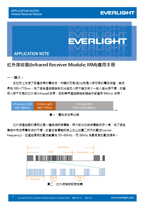
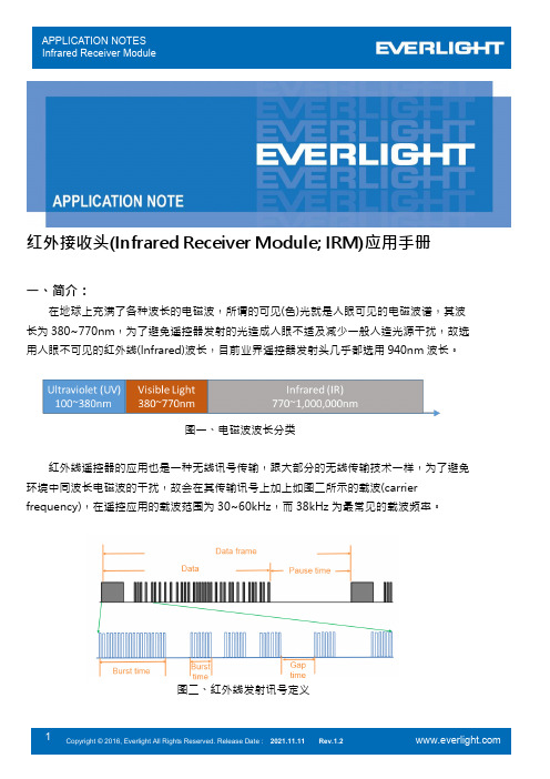
紅外接收器(Infrared Receiver Module; IRM)應用手冊一、簡介:在地球上充滿了各種波長的電磁波,所謂的可見(色)光就是人眼可見的電磁波譜,其波長為380~770nm,為了避免遙控器發射的光造成人眼不適及減少一般人造光源干擾,故選用人眼不可見的紅外線(Infrared)波長,目前業界遙控器發射頭幾乎都選用940nm波長。
圖一、電磁波波長分類紅外線遙控器的應用也是一種無線訊號傳輸,跟大部分的無線傳輸技術一樣,為了避免環境中同波長電磁波的干擾,故會在其傳輸訊號上加上如圖二所示的載波(carrier frequency),在遙控應用的載波範圍為30~60kHz,而38kHz為最常見的載波頻率。
圖二、紅外線發射訊號定義二、使用說明:一般紅外遙控系統除了載波外,還有通訊協定(IR protocol),不同的IRM能支援的協定均不相同;在選用IRM前,請先參考規格書中如表一的支援協定列表是否支援,另須注意協定的載波頻率和IRM型號是否匹配(億光IRM產品不同頻率但相同晶片的IRM型號會共用規格書)。
IRM載波頻率在出廠時就會燒定,若選擇38kHz中心頻率的IRM,也可接收36kHz 或40KHz的紅外通訊協定,但接收距離會較38kHz載波頻率的協定短,故選擇正確中心頻率的IRM才能得到最佳接收距離,各型號IRM能選擇的中心頻率請參考規格書中如圖三、支援載波頻率及相對靈敏度。
1.) 有支援的紅外協定都可支援長按(repeat)操作。
2.) Continuous Code一般指的是Pause time小於10ms的連續發射訊號。
圖三、支援載波頻率及相對靈敏度一般的IRM是無法一直連續的接收載波訊號,除了圖二定義的休息時間較短的gap time(通常1ms以下),每經過一組完整數據(Data)還需有休息時間較長的Pause time(10ms以上),故若使用的紅外協定沒有列在規格書的表中或有特殊考量需使用自訂的協定,須注意如底下規格書所列的最小需求(每個型號不同,需看相對應型號的規格書)。
一体红外线接收头工作原理及其应用

⼀体红外线接收头⼯作原理及其应⽤简单了解红外遥控器⼯作原理红外遥控是⽣活中除⽆线电波遥控以外最常⽤的⼀种⽆线控制⽅式。
红外遥控具有体积⼩、功耗低、成本低等特点,在常见的家⽤电器中,如电视机、空调、机顶盒、⾳响、⼉童玩具等都被⼴泛应⽤。
红外遥控器采⽤的是载波通信⽅式,它将经过编码的数据与固定频率的相叠加,通过这种⽅式进⾏通信可以有效地提⾼发射效率,同时会降低功耗。
红外遥控常⽤的载波频率为38kHz,所以在红外遥控器中会见到频率为455kHz的晶振,晶振通过分频器进⾏12分频后得到约为38kHz的频率。
红外遥控器中常见的455kHz陶瓷晶振经过编码和调制之后的信号会经过放⼤电路放⼤,之后通过红外发光⼆极管发射出去。
接收电路接收到红外信号之后,对信号进⾏放⼤和滤波等处理之后,送⾄后级解码电路,就可以还原出遥控器所发出的按键功能。
⼀体红外线接收头⼯作原理由于环境光线中的可见光以及其他频率的红外线都会被红外接收部分接收,为了防⽌这些光线对信号造成⼲扰,就需要通过滤光、滤波电路等对接收到的信号进⾏“筛选”。
普通的红外线⼆极管外壳会做成红褐⾊,从⽽对部分可见光进⾏滤除,但是⽆法滤除其他频率的红外光。
常见红外线接收⼆极管⼀体红外线接收头除对部分可见光进⾏滤除外,其内部滤波电路会对某个特定频率范围之内的红外线进⾏“筛选”,由于⼤部分的红外遥控器为38kHz的载波频率,所以常⽤的⼀体红外接收头的中⼼频率为38kHz,并且内部集成了放⼤电路,其输出的信号可直接进⼊解码电路使⽤,⽆需增加额外的电路。
⼀体红外线接收头⼀体红外线接收头内部结构⼀体红外线接收头内部包含红外接收电路、滤波电路、限幅电路、放⼤电路、积分电路等⼏部分。
接收到的光信号通过外壳的滤光之后进⼊内部红外接收⼆极管,接收⼆极管输出的信号经过初级放⼤和限幅电路后,将信号幅度限定在⼀定范围内,这样不会因为遥控器的距离远近⽽造成信号的过⼤浮动。
经过初步放⼤的信号会进⼊滤波和积分电路,最终的会通过⽐较器或触发器等电路,将输⼊的信号还原成⽅波信号输出。
红外线遥控接收头型号及参数:

红外线遥控接收头型号及参数:红外线遥控接收头HS0038B第1脚为信号输出第2脚为电源地第3脚为电源正接收电路工作原理为:当接收到载波频率为38KHz的脉冲调制信号时,首先,HS0038B内的红外敏感元件将脉冲调制红外光信号转换成电信号,再由前置放大器和自动增益控制电路进行放大处理,然后通过带通滤波器进行滤波,滤波后的信号由解调电路进行解调,最后由输出电路进行反向放大并输出低电平;未接收到载波信号时,电路则输出高电平。
一体化红外遥控接收头SH0038、SCR638型管脚识别一体化红外遥控接收头型号:PNA4602M 型管脚识别一体化红外线接收头RPM-638CBR型管脚识别红?外?一?体?化?接?收?头?型号:T?S?O?P?1?8?3?8管脚识别:一体化红外线接收头原理图及管脚排列什么是遥控接收头?所谓接收头就是将光敏二极管和放大电路组合到一起的元件,这些元件完成接收、放大、解调等功能。
所有红外线遥控器的输出都是用编码后的串行数据对30~56kHz的方波进行脉冲幅度调制而产生的。
如果直接对已调波进行测量,由于单芯片系统的指令周期是微秒(μs),而已调波的脉宽只有20多μs,会产生很大的误差。
因此先要对已调波进行解调,对解调后的波形进行测量。
红外一体化接收头:红外线接收头一般是接收、放大、解调一体头,一般红外信号经接收头解调后,数据“0”和“1”的区别通常体现在高低电平的时间长短或信号周期上,单片机解码时,通常将接收头输出脚连接到单片机的外部中断,结合定时器判断外部中断间隔的时间从而获取数据。
重点是找到数据“0”与“1”间的波形差别。
输出端可与CMOS、TTL电路相连,这种接收头广泛用在空调,电视,VCD等电器中。
早期的红外一体化接收头一般由集成电路与接收二极管焊接在一块电路板上完成的,这种接收头具有体积大的缺点,现在的接收头是集成电路与接收二极管封装在一起的,不可拆,不可修,体积很小。
大多数接收头供电为5V,有极少数早期的接收头为12V供电。
IRM138系列红外线接收头

广泛应用于音响、电视、DVD、VCD、DVB;空调、风扇、电表、灯饰、 电子玩具等家用电器红外遥控,感应洁具、光电感应开关等红外应用场 合。
IRM138 系列产品属于常规鼻梁外观,外表光滑美观,具有红外穿透性 良好、接收灵敏度高的特点。 1. 内置 PIN 光电二极管,前置放大器,采用一体化内屏蔽封装; 2. 内置 PCM 频率环,TTL,CMOS 电平均适用; 3. 低电平有效,电压为 2.7~5.5V 宽电压; 4. 外形尺寸(单位 mm)6.8×5.85×5.15,脚距:2.54。
IRM138S-6
40
0.4
0.4
●●●○○●
57
IRM138N
2.7~6.0 25 37.9
1.0
IRM138NS
2.7~6.0 25 37.9
1.0
IRM138NL
2.7~6.0 25 37.9
1.0
IRM138LM
2.7~6.0 20 37.9
0.8
IRM138C
2.7~6.0 20 37.9
型号
IRM138HL-26 IRM138S-2
工作电 压范围 (V)
2.7~5.5
最远
性能特征
载波频
接收
电
连
工作电 静态电 灵 光
兼
功
磁
续
率 流(mA) 流(mA) 敏 干
容
耗
距离 (KHZ)
干
编
度扰
性
低
扰
码
(M)
30 37.9
1.0
0.8
●●●●○○
37.9
1.0
0.5
●●●○○○
36
红外接收头规格书
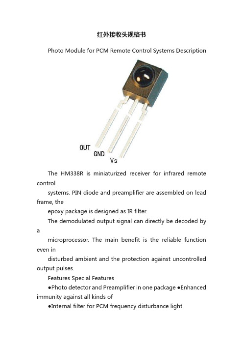
红外接收头规格书Photo Module for PCM Remote Control Systems DescriptionThe HM338R is miniaturized receiver for infrared remote controlsystems. PIN diode and preamplifier are assembled on lead frame, theepoxy package is designed as IR filter.The demodulated output signal can directly be decoded by amicroprocessor. The main benefit is the reliable function even indisturbed ambient and the protection against uncontrolled output pulses.Features Special Features●Photo detector and Preamplifier in one package ●Enhanced immunity against all kinds of●Internal filter for PCM frequency disturbance light●TTL and CMOS compatibility ●No occurrence of disturbance pulses at●Output active low the output● Low power consumption● Suitable burst length ≥10 cycles/burstApplicationsTV, VTR, Acoustic Devices, Air Conditioner, Car Stereo Units, Computers, Interior controlling appliances, and all appliances that require remote controllingBlock DiagramApplication Circuit*) recommended to suppress power supply disturbanceAbsolute Maximum RatingsTamb = 25 ℃ParameterTest ConditionsSymbol Value UnitSupply V oltage (Pin 3) Vs 6.0 V Supply Current (Pin 3) Is 5 mA Output V oltage(Pin 1) V o 6.0 V Storage Temperature Range Tstg -30…+105 ℃ Operating Temperature Range Tamb -25…+85 ℃ Power Consumption (Tamb ≦ 85 ℃) ptot 50 mW Soldering Temperature t ≦ 5s Tsd 260 ℃Basic Characteristics (Ta=25℃)ParameterTest ConditionsSymbolMinTypMaxUnitSupply Current (Pin3) Vs = 5V , Ev = 0 I SD 0.7 1.1 2 mA Supply V oltage (Pin3)Vs 2.7 5.5 V Transmission Distance IR diode AT205, I F = 400 mAd20mOutput V oltage High (Pin1) V OH 4.5VOutput V oltage Low (Pin1) Vs = 5VCycle 1.2mS , 50% duty V OL 250 mV Level Output Pulse Width T WH 500 800 μs Level Output Pulse Width (Pin1) Cycle 1.2mS , 50% dutyT WL 500 800 μs Carrier frequency fo37.9kHzPeak Wavelengthλ 940 nm DirectivityAngle of half transmission distanceφ1/2 ±45 degReliability TestTEST ITEMTESTCONDITIONTEST TIMESAMPLENUMOKNUMHigh Temperature Storage Ta=+85℃ t=240H2222Low Temperature Storage Ta=-25℃ t=240H2222Resistance to soldering heat Soak into solder tub of Tsd=260℃1cycle 5sec 22 22Electro Static DischargeHBM C=100pF,R=1.5k?, 2kV,each pin test once 22 22 High Temperature/Humidity* Ta=+85℃, 90%RH t=240H 22 22 Heat Cycle* -25℃~+85℃(0.5H) 20cycle 22 22 Note : *(electro-optical characteristics) shall be satisfied after leaving 2 hours in the normal temperature Suitable Data Formatz Minimum burst length(t burst) of 10 pulses per burstz Minimum burst gap time(t burst gap) 14 pulsez Minimum data pause time( t pause)>25msecz Output active lowz Some examples for suitable data format are:NEC Code, Sharp CodeCharacteristics Curve(Tamb=25℃ unless otherwise specified)0°15°30°45°60°75°1.00.80.40.60.20.90.40.60.2d rel -Relative Transmission Distance Figure 3.Horizontal DirectivityPackage OutlineDimensions in mm: tolerance±0.3mm。
亿光红外线发射接收管红外系列产品基础知识解答
亿光红外线发射接收管红外系列产品基础知识解答
亿光的光电元器件产品型号有上千种,亿光代理商超毅电子跟大家讲解一下关于亿光的红外系列产品的基础常识,让大家更加熟悉亿光的产品。
亿光红外线发射接收管红外系列产品基础知识解答:
问:亿光IRM接收头主要分为哪种类型?
答:M-Type、C-Type、M2-Type、M3-Type、T-type
问:无线鼠标对LED的要求是低电压以省电,有哪些亿光发射管适用于无线鼠标?
答:HIR8383C/L289、SIR8383C/L492、HIR8323C
问:适用于电表行业的亿光元器件有哪些?
答:红外发射管:IR333/H0/L10、IR323/H0-A,接收头:IRM-3638MF4、IRM-3638TF4
光耦:EL816S1(D)(TA)-F、EL816S(D)(TA)
指示灯5mm:333-2SURD/S530-A3-L、333-2SYGD/S530-E2-L、
333-2UYD/S530-A3-L
指示灯3mm:204-10SURD/S530-A3-L、204-10SYGD/S530-E2-L、
204-10UYD/S530-A3
问:智能水表能用到亿光的型号有哪些?
答:MPT6036C/3T接收管、MPT6036T接收管、19-217/R6C-Al1M2VY/3T 0603红灯
问:亿光红外线产品中SIR和HIR的光波波分别长是多少?
答:875nm和850nm
问:亿光红外线IR333C/HO/L10产品编码原则中晶高代码是哪一个?
答:HO
问:亿光红外线产品中IR/PT/PD的生产流程主要是怎么样的?
答:固晶-焊线-封膠(壓模)-切腳-測試-包裝-送檢-入庫。
红外线专用接收头资料

红外线遥控接收头原理:三条腿的红外线遥控接收头一般是接收放大、解调一体头,接收头输出的是解调后的数据信号(具体的信号格式,搜“红外信号格式”一大把),单片机里面需要相应的读取程序。
红外通信是利用红外技术实现两点间的近距离保密通信和信息转发。
它一般由红外发射和接收系统两部分组成。
发射系统对一个红外辐射源进行调制后发射红外信息,而接收系统用光学装置和红外探测器进行接收,就构成红外通信系统。
红外线遥控接收头的简介:红外线遥控接收头是目前使用最广泛的一种通信和遥控手段。
由于红外线遥控装置具有体积小、功耗低、功能强、成本低等特点,因而继彩电、录像机之后,在录音机、音响设备、空调机以及玩具等其它小型电器装置上也纷纷采用红外线遥控。
工业设备中,在高压、辐射、有毒气体、粉尘等环境下,采用红外线遥控不仅完全可靠而且能有效地隔离电气干扰。
红外线专用接收头的封装形式有两种:一种采用铁皮屏洞屏蔽,一种是塑料封装。
均有三只引脚,即电源正(VDD)、电源负(GND)和数据输出(VOUT)。
红外线接收头的引脚排列因数型号不同而不尽相同,可参考厂家的使用说明。
成品红外接收头的优点是不需要复杂的调试和外壳屏蔽,使用非常方便。
但在使用时注意成品红波形,在接收端收到接收信号时,接头的输出的波形正好和遥控芯片输出的相反。
红外线遥控接收头常用的载波频率为38kHz,这是由发射端所使用的455kHz晶振来决定的。
在发射端要对晶振进行整数分频,分频系数一般取12,所以455kHz÷12≈37.9 kHz≈38 kHz。
也有一些遥控系统采用36 kHz、40 kHz、56 kHz 等,一般由发射端晶夺的振荡频率来决定。
红外线接收头参数:工作时消耗电流0.8mA-1mA,接收频率:38kHz-56kHz,峰值波长940nm,接收距离L0°=15m、L45°=8m,高水平脉冲宽度400-800μs,低电平脉冲宽度400-800μs,高电平输出电压2.7V,低电平输出电压0.25V。
红外接收头(Infrared Receiver Module; IRM)应用手册说明书
红外接收头(Infrared Receiver Module; IRM)应用手册一、简介:在地球上充满了各种波长的电磁波,所谓的可见(色)光就是人眼可见的电磁波谱,其波长为380~770nm,为了避免遥控器发射的光造成人眼不适及减少一般人造光源干扰,故选用人眼不可见的红外线(Infrared)波长,目前业界遥控器发射头几乎都选用940nm波长。
图一、电磁波波长分类红外线遥控器的应用也是一种无线讯号传输,跟大部分的无线传输技术一样,为了避免环境中同波长电磁波的干扰,故会在其传输讯号上加上如图二所示的载波(carrier frequency),在遥控应用的载波范围为30~60kHz,而38kHz为最常见的载波频率。
图二、红外线发射讯号定义二、使用说明:一般红外遥控系统除了载波外还有其通讯协议(IR protocol),不同型号的IRM能支持的协议均不相同;在选用IRM前,请先参考规格书中如表一的支持协议列表是否支持,另须注意协议的载波频率和IRM型号是否匹配(亿光IRM产品不同频率但相同芯片的IRM型号会共享规格书)。
IRM载波频率在出厂时就会烧定,若选择38kHz中心频率的IRM,也可接收36kHz 或40KHz的红外通讯协议,但接收距离会较38kHz载波频率的协议短,故选择正确中心频率的IRM才能得到最佳接收距离,各型号IRM能选择的中心频率请参考规格书中如图三、支持载波频率及相对灵敏度。
1.) 有支持的红外协议都可支持长按(repeat)操作。
2.) Continuous Code一般指的是Pause time小于10ms的连续发射讯号。
图三、支持载波频率及相对灵敏度一般的IRM是无法一直连续的接收载波讯号,除了图二定义的休息时间较短的gap time(1ms 以下),每经过一组完整数据(Data)还需有休息时间较长的Pause time(10ms以上),故若是使用的红外协议没有列在规格书的表中或有特殊考虑需使用自定义的协议,须注意如底下规格书所列的最小需求(每个型号不同,需看相对应型号的规格书)。
TM-RF高清红外用户手册说明书
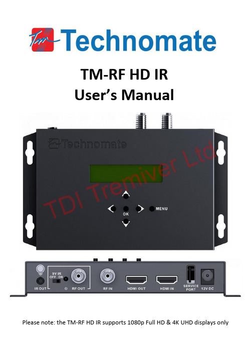
TM-RF HD IRUser’s ManualPlease note: the TM-RF HD IR supports 1080p Full HD & 4K UHD displays only1. IMPORTANT SAFETY INSTRUCTIONS• To prevent fire or shock hazard, do not expose any part of the devices to rain or moisture.• This product is for indoor use only.• Do not install near and heat sources such as radiators, heat registers, stoves or other apparatus (including amplifiers) that produce heat.• Clean only with a dry cloth• Protect the power cord from being walked on or pinched particularly at plug, convenience receptacles, and the point where it exits from the apparatus.• Unplug this appara tus during lightning storms and when unused for long periods of time.• Refer all servicing to qualified service personnel.• Do not expose the equipment to dripping or splashing and ensure that no objects filled with liquids, are placed on the equipment.• This device should be operated using only the AC/DC adaptor supplied with it.• Do not overload wall outlets and extension cords as this can result in the risk of fi re or electrical shock.2. CONTENTS1 x TM-RF HD IR1 x 12V DC Power Supply Adaptor1 x IR Transmitter1 x 9V IR Adaptor1 x Owner’s Manual3. CONNECTIONS1. IR Transmitter (to source device)2. 9V IR ON/OFF Switch3. RF Output (to TV)4. RF Input (for cascading or aerial input)5. HDMI Output (loop-through)6. HDMI Input7. USB Service Port (for software update/download)8. 12V DC Power Input4. MenusStream (please note that the TM-RF HD IR has been defaulted to UK settings):1.Country: select a country for your UHF settings. Default is UK.a.Press Menu buttonb.Go to STREAM via ⇧⇩ buttons and press OKc.Go to COUNTRY via ⇧⇧ buttons and press OKd.Change country via ⇧⇩ buttonse.Press OK to confirm22. Channel: enter a UHF channel number. Check which channels/frequencies are being used by your local television stations to avoid conflict. It’s best to select a channel that is unoccupied. For example, in the UK, Channel 21 is unoccupied. Default is: 21a. Press MENU buttonb. Go to STREAM via ⇧⇩ buttons and press OKc. Go to CHANNEL via ⇧⇩ buttons and press OKd. Change numbers via ⇧⇩ buttonse. Press OK to confirmPlease note which UHF channels are used for 4G/LTE transmissions (normally channels above 61) as a 4G/LTE filter may be required to avoid interference (not included).3. Service Name: enter a channel name which will appear in your TV’s channel list. Default is: TV1a. Press MENU buttonb. Go to STREAM via ⇧⇧ buttons and press OKc. Go to SERVICE NAME via ⇧⇩buttons and press OKd. Edit letters via ⇧⇩⇦⇨ buttonse. Press OK to confirm4. Service ID: allocate an ID. Default is: 1.a. Press MENU buttonb. Go to STREAM via ⇧⇩ buttons and press OKc. Go to SERVICE ID via ⇧⇩ buttons and press OKd. Edit number via ⇧⇩⇦⇨ buttonse. Press OK to confirm5. Network Name: enter a network name which may appear in your TV’s channel list.a. Press MENU buttonb. Go to STREAM via ⇧⇩ buttons and press OKc. Got to NETWORK NAME via ⇧⇩ buttons and press OKd. Edit letters via ⇧⇩⇦⇨ buttonse. Press OK to confirm6. Provider Name: enter a provider name which may appear in your TV’s channel list.a. Press MENU buttonb. Go to STREAM via ⇧⇩ buttons and press OKc. Go to PROVIDER NAME via ⇧⇩ buttons and press OKd. Edit letters via ⇧⇩⇦⇨ buttonse. Press OK to confirmAdvanced (please note that the TM-RF HD IR has been defaulted to UK settings):1. LCN Mode: select a region or select Manual to enter a number. Default is: ITCa. Press MENU buttonb. Go to ADVANCED via ⇧⇩ buttons and press OKc. Go to LCN MODE via ⇧⇩ buttons and press OKd. Select a region or select Manual to enter a number via ⇧⇩ buttonse. Press OK to confirm2. LCN ID: enter a number. Default is: 800 which is an unused area of the EPG. Provided that 3 3Your display supports LCN (also check LCN is ON in your display), this will be the channel number you enter into your displays remote to watch the TM-RF HD IR’s channel.If you would like to use a lower number, please check the first free slot in your EPG and that can be you LCN ID number.a.Press MENU buttonb.Go to ADVANCED via ⇧⇩ buttons and press OKc.Go to LCN ID via ⇧⇩ buttons and press OKd.Enter a number via ⇧⇩⇦⇨ buttonse.Press OK to confirm3.TSID: Default is: 128a.Press MENU buttonb.Go to ADVANCED via ⇧⇩ buttons and press OKc.Go to TSID via ⇧⇩ buttons and press OKd.Enter a number via ⇧⇩⇦⇨ buttonse.Press OK to confirm4. ONID: Auto will automatically configure ONID for all countries or select Manual to enter a number.Default is: AUTOa.Press MENU buttonb.Go to ADVANCED via ⇧⇩ buttons and press OKc.Go to ONID via ⇧⇩ buttons and press OKd.Select a country or select Manual to enter a number via ⇧⇩⇦⇨ buttonse.Press OK to confirm5. Network ID: Auto will automatically configure Network ID for all countries or select Manual to enter a number Default is: AUTOa.Press MENU buttonb.Go to ADVANCED via ⇧⇩ buttons and press OKc.Go to NETWORK ID via ⇧⇩ buttons and press OKd.Select a country or select Manual to enter a number via ⇧⇩⇦⇨ buttonse.Press OK to confirm6. Bandwidth: select 6, 7 or 8MHz. Default is: 8MHza.Press MENU buttonb.Go to ADVANCED via ⇧⇩ buttons and press OKc.Go to BANDWIDTH via ⇧⇩ buttons and press OKd.Select bandwidth via ⇧⇩ buttonse.Press OK to confirm7. Constellation: select QPSK, 16QAM, or 64QAM. Default is 64QAMa.Press MENU buttonb.Go to ADVANCED via ⇧⇩ buttons and press OKc.Go to CONSTELLATION via ⇧⇩ buttons and press OKd.Select constellation via ⇧⇩ buttonse.Press OK to confirm8. FEC: select 1/2, 2/3, 3/4, 5/6, or 7/8. Default is: 7/8a.Press MENU buttonb.Go to ADVANCED via ⇧⇩ buttons and Press OKc.Go to FEC via ⇧⇩ buttons and press OK4d.Select a FEC via ⇧⇩ buttonse.Press OK to confirm9.Guard Interval: 1/4, 1/8, 1/16 or 1/32. Default is: 1/32a.Press MENU buttonb.Go to ADVANCED via ⇧⇩ buttons and press OKc.Go to GUARD INTERVAL via ⇧⇩ buttons and press OKd.Select an interval via ⇧⇩ buttonse.Press OK to confirm10. Carrier Rate: 2K or 8K. Default is: 8Ka.Press MENU buttonb.Go to ADVANCED via ⇧⇩ buttons and press OKc.Go to CARRIER RATE via ⇧⇩ buttons and press OKd.Select a rate via ⇧⇩ buttonse.Press OK to confirm11. Video Bitrate: adjust the video compression size. Default is: 18,000 Mbpsa.Press Menu buttonb.Go to ADVANCED via ⇧⇩ buttons and press OKc.Go to VIDEO BITRATE via ⇧⇩ buttons and press OKd.Enter a number via ⇧⇩⇦⇨ buttonse.Press OK to confirm12. Audio Bitrate: adjusts the audio compression size. Default is: 192 kbpsa.Press MENU buttonb.Go to ADVANCED via ⇧⇩ buttons and press OKc.Go to AUDIO BITRATE via ⇧⇩ buttons and press OKd.Select a rate via ⇧⇩ buttonse.Press OK to confirm13. Audio Format: adjusts the audio type. Default is: MPEGa.Press Menu buttonb.Go to ADVANCED via ⇧⇩ buttons and press OKc.Go to AUDIO FORMAT via ⇧⇩ buttons and press OKd.Select a format via ⇧⇩ buttonse.Press OK to confirm14. Audio Sync: to adjust the audio delay. Default is: 0a.Press Menu buttonb.Go to ADVANCED via ⇧⇩ buttons and press OKc.Go to AUDIO SYNC via ⇧⇩ buttons and press OKd.Enter a number via ⇧⇩⇦⇨ buttonse.Press OK to confirm15. dB Level: to adjust the dB strength from RF OUT. Default is: 0 dBa.Press MENU buttonb.Go to ADVANCED via ⇧⇩ buttons and press OKc.Go to dB LEVEL via ⇧⇩ buttons and press OKd.Enter a number via ⇧⇩ buttonse.Press OK to confirm5System:1.Version: Shows current software version2.Reset: to the factory default all settings.3.Upload: Uploads current configuration in order to edit data when cascading.5.INSTALLATION – Basic1.Connect a source device to the HDMI input. The HDMI Output can be used to send a HDMI signal to a local TV.2.Connect a coaxial cable (75Ohm) from the RF OUT to an aerial/antenna input on a TV.3.The default UHF Channel is 21. You can change this in the Channel menu (please refer to4. Menus).4.The default country is PAL-I UHF 21-69, United Kingdom. In the Country menu (please refer to 4. Menus), you canalso select systems from: Denmark, Finland, France, Italy, Spain and Sweden.5.In your TV, go to Terrestrial Search (may also be called, Aerial, Antenna, Freeview, etc.) and search using theDigital Scan/Search option. You can also do a Manual Digital Search and enter the Channel Number you selected in the TM-RF HD IR (default is 21), for a faster search.6.You can connect an existing aerial into the RF IN or in you have more than one TM-RF HD IR, you can cascadeanother TM-RF HD IR into it.7.If you have more than one TV, you can use a passive splitter or an amplified (mains powered) splitter from the RFOUT of the TM-RF HD IR into the Input of a passive splitter or the UHF Input of unamplified splitter. For further information, please see the following section.6.INSTALLATION – Using the 9V IR Infra-Red AdapterThis allows an IR Infra-Red remote control signal to be transmitted along the same coaxial cable so that you can control your source device from another TV. If you would like to control on more TV’s, you will require more IR adapters (sold separately) and please refer to 7.a. Amplified Splitter.1.Turn ON the 9V switch on the back of the TM-RF HD IR.2.At the second TV, connect the 9V IR Adapter to the coaxial cable coming from the TM-RF HD IR.3.Then connect the IR adapter your TV and LED on the IR Adapter will light up.67.INSTALLATION – Advanced7.a. Watching on more than 1 TV∙Passive Splitter (non-mains powered, DC Pass recommended) – if you would like to only watch video/audio without having the option to use an IR remote control, you can use a passive splitter. We can recommend up to3 cascades.Furthermore, you can loop the outputs of a passive splitter. For example, you can connect/cascade two 4-way splitters together so you can watch on up to 7 TV’s.∙Amplified Splitter (mains powered, distribution amplifier) – there are two types: Bypass(IR, required for the 9V IR Adapters) and Non-Bypass (Non-IR, also known as Aerial Distribution Amplifiers).Bypass – the advantage with a Bypass amplifier is that you can control your HDMI source device from every TV as IR Infra-Red remote control signals are transmitted via the same coaxial cable. You will also require a 9V IR Adapter (1 included) for each TV which will send the IR signal from your TV to the source device.*All Splitters, Amplifiers and Adapters are available from Technomate, sold desperately.7.b. To have more than 1 HDMI Source DeviceYou can use up to 35 TM-RF HD IR’s in one system by cascading the modulators. This allows you to use up 35 HDMI source devices, allocated to different channels.If using an aerial in the same system, please check your local aerial transmitter to see which channels are not used in order to avoid channel conflict/interference. We recommend channels to be 2 channels apart to avoid conflict and tobe less than CH60 to avoid 4G LTE interference.To set up the cascade system:1.Connect the RF OUT of the first modulator to the RF IN of the second modulator, and so forth2.Each modulator will need different:a.Channel Number (UHF Number)b.Service Namec.Service IDd.LCN IDe.Provider Name (optional, Provider Name can be the same on all modulators)For example, the first modulator could be set to Channel 21, Service Name BBC1, Service ID 1, LCN ID 800, Provider Name TM. The second could be set to Channel 23, Service Name BBC2, Service ID 2, LCN ID 801, Provider Name TM1 (or TM), etc.The cascade configuration can also be done on a PC to save time. Please contact Technomate for the file or you can upload it directly to your USB, refer to 8. Update & Configuration.3.The RF Out of the final modulator can be connected to a TV or to a splitter (as in 6.a.).77.c. Connecting an aerial systemIf you have a UHF TV aerial, you can connect this to the RF IN.The RF OUT will then combine video/audio of the source with your TV signal, so that when you do an automatic digital scan on your TV, it will find the TM-RF HD IR channel as well as all your TV channels.If some aerial channels have an issue, such as distortion, the current dB may be too high. Please decrease the dB in: Menu – Advanced – dB Level.7.b. Defining Channel Numbers in your TV’s channel listIf your TV supports LCN, the TM-RF HD IR will appear in your TV’s channel list as the channel number you selected. The default is 800 which means the TM-RF HD IR will appear as channel 800 in your EPG of your TV after all your TV / Radio channels.You will need to check which LCN numbers are free in your EPG to allocate a different number.If after a search, the channel appears at a different number, this means that the LCN number you chose is not available or that your TV does not support LCN.If you are not using an aerial/antenna, then the LCN can be set to 1 to appear as Channel 1 in your EPG and TV.Please also check that LCN in your TV is ON as it may be defaulted to OFF.8. UPDATE & CONFIGURATION1. To update to the latest softwarea.Copy the TM-RF HD IR software file to the root directory of your USB drive (FAT32 format).b.Turn the power of the TM-RF HD IR OFF.c.Connect the USB to the USB Service Port.d.Turn the power ON.e.The file will automatically install within a few seconds.f.Remove the USB after the TM-RF HD IR has finished booting up.2. To update to the Cascaded Settingsa.Connect a USB drive (FAT32 format) to the USB Service Port.b.Go to System - Upload.e Notepad on a PC to open and edit the file.d.Each file should have unique settings only for the following information:i.Channel Numberii.Service Nameiii.Service IDiv.Provider Namev.LCN ID8e.Once finished, save the file (do not change the files name) and copy to your USB drive’s root directory.f.Turn the power of the TM-RF HD IR OFF.g.Connect the USB to the USB Service Port.h.Turn the power ON.i. A message will pop-up to say: Update Cascade?j.Select YES.k.Remove the USB after the TM-RF HD IR has finished booting up.9. TROUBLESHOOTING1. No Video/Audio, Channel not found when Scanninga.Ensure that your TV is 1080p Full HD or 4K UHD and has a DVB-T Digital Tuner.b.When doing a scan, please ensure you have selected the Digital Scan / Search option. Analogue Search willnot find the TM-RF HD IR.c.Try a different Channel Number. Check that the channel number is not conflicting with your localtransmitter, for example, in London BBC 1 is on channel 23 so if you selected Channel 23 in the TM-RF HD IR,it would not work.Furthermore, check that the selected channel number is not conflicting with other transmissions such at4G/LTE (normally above Channel 61).d.The software in your TV may be out of date. Please update your TV to ensure it has the latest software. Thisis normally found in Settings or Maintenance menus.e.Try a different HDMI cable.f.Disconnect HDMI cables, any cable going into RF IN, leaving only RF OUT connected. Try another scan.g.Please check your country is selected in Menu – Stream – Country.h.If you have connected an aerial / antenna to the RF IN, please remove it and try another scan on your TV tosee if it shows the vide.If this works without the aerial / antenna connected, please try 1.i. belowi.Different channel numbers have different dB signal strengths. Furthermore, if using an amplifier or poweredsplitter, this will affect the dB too. If the dB is too high, there will be no video or the channel may not befound.The output signal from the RF OUT may be too high or too low as a result, therefore please adjust the dB inthe Menu – Advanced – dB Level by for example, -5 dB, -10 dB and then rescan the channel.j.Ensure that your TV’s DVB-T tuner is compatible with MPEG-4. If it is not, you will require a DVB-T2 Set-Top Box for the TM-RF HD IR to connect to in order to make the modulator compatible with your TV.k.Try a Factory Reset and scan again.2. LCN not workinga.Ensure that your TV supports LCN.b.Check that LCN is ON in your TVc.Ensure that LCN you entered is free in your TV’s EPG.910. DELAY TIMEThe TM-RF HD IR has a very fast delay time of less than 0.8 seconds, therefore channel change speeds will only take less than 0.8 seconds.For video only source devices such as CCTV products, this can be even faster. Please contact your supplier or Technomate for further information.11. SPECIFICATIONS1080p@50/60HzAspect Ratio 16:, 4:3Bit Rate 1.000 ~ 30.000 MbpsAudio Encoding MPEG-1 Layer 2Sample Rate 48KHzBit Rate 64, 96, 128, 192, 256, 320 kbpsModulatorStandard DVB-T COFDMBandwidth 6M, 7M, 8MConstellation QPSK, 16QAM, 64QAMCode Rate 1/2, 2/3, 3/4, 5/6, 7/8Guard Interval 1/32, 1/16, 1/8, 1/4Transmission Mode 2K, 8KRF Frequency 142.5 ~ 858 MHzLCN Support YesInfra-Red 9V IR Compatible10。
HS138规格书
Tamb=260°C 10±1 秒, 1 次,距封装体 1mm
待测器件从 75cm 高度自然的下落在硬木板上,三次
注:1. 在正常温度下放置 2 小时后仍满足电气参数。 2. 没有外观变形(管脚变形除外),且仍满足电气参数
标准 注1 注1 注1 注1 注1 注2
参数
符号 测试条件
最小值
工作电压
VCC
2.7
工作电流
ICC
IIN=0
--
输出脉冲宽度
tPW1 fin=f0, 输入脉冲波 Vin=500 μVp-p ,注1
400
tPW2 fin=f0, 输入脉冲波 Vin=500mVp-p ,注1
400
低电平输出电压
VOL
--
高电平输出电压
VOH
VCC-0.3
接收距离
λp
--
中心频率 (B.P.F)
f0
--
典型值 5.0 0.9 -----
18
0.35 0.4 -±45 940 37.9
最大值 5.5 1.6 800 800 200 VCC
单位 V mA μs μs mV V
--
m
0.5 mW/m2 0.6 mW/m2 -- mW/m2
--
deg
--
nm
--
KHz
30°
1.0 0.9 0.8 0.7
0.6 0.4 0.2 0
40°
50° 60° 70° 80°
■可靠性测试
测试项目
测试条件
高温储存
Tamb=+85°C
t=500H
高温高湿储存 低温储存 温度循环 耐焊接热 跌落试验
Tamb=+85℃,85%RH
IRM138H红外接收头说明
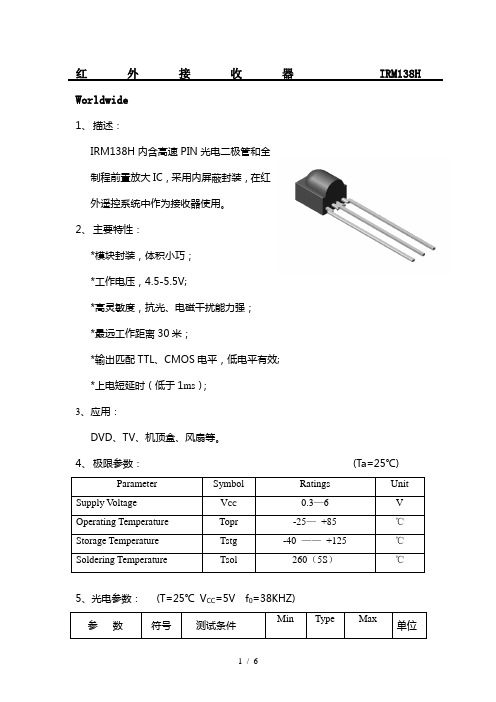
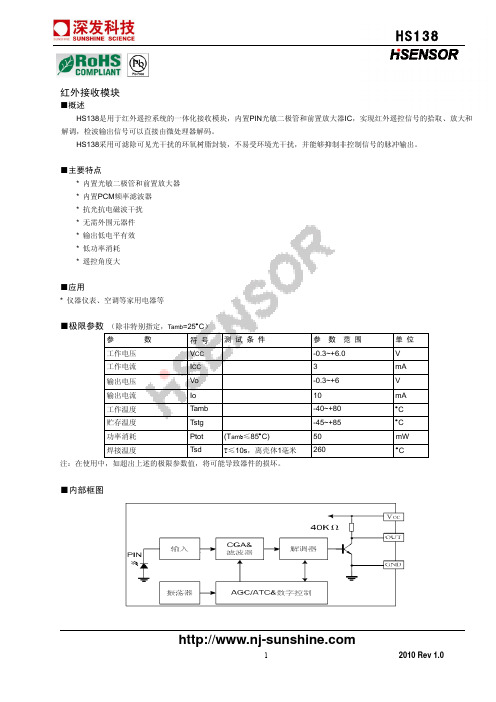
红外接收器IRM138H Worldwide1、描述:IRM138H内含高速PIN光电二极管和全制程前置放大IC,采用内屏蔽封装,在红外遥控系统中作为接收器使用。
2、主要特性:*模块封装,体积小巧;*工作电压,4.5-5.5V;*高灵敏度,抗光、电磁干扰能力强;*最远工作距离30米;*输出匹配TTL、CMOS电平,低电平有效;*上电短延时(低于1ms);3、应用:DVD、TV、机顶盒、风扇等。
4、极限参数:(Ta=25℃)Parameter Symbol Ratings UnitSupply V oltage V CC0.3—6 VOperating Temperature Topr -25—+85 ℃Storage Temperature Tstg -40 ——+125 ℃Soldering Temperature Tsol 260(5S)℃5、光电参数:(T=25℃V CC=5V f0=38KHZ)参数符号测试条件Min Type Max 单位工作电压V CC 4.5 5.0 5.5 V工作电流Icc 1.0 mAIce 无信号输入时0.8 1.5 mA静态电流内部上拉电阻R PU30/40 KΩ输出电流I OCL8 mA接收距离L 15 20 30 M接收角度θ1/2 +/-45 Deg载波频率f038 KHZBMP 宽度f BW-3Db Bandwidth f0-1.5 f0f0+1.5 kHz低电平输出V OL Vin=0V Vcc=5V 0.25 V高电平输出V OH Vcc=5V V CC-0.25 V CC V红外接收器IRM138H Worldwide6、特性曲线:红外接收器IRM138H Worldwide红外接收器IRM138H Worldwide6、测试波形:7、电原理图:8、应用电路:红外接收器IRM138HWorldwide9、尺寸:[文档可能无法思考全面,请浏览后下载,另外祝您生活愉快,工作顺利,万事如意!]。
电表专用红外线接收头IRM38BNH
试以下参数:
1000H
距离:L≥15m 20 受控角:
△θ≥45deg
85±2)℃1000H
5
高温储存
100
100
13、使用注意事项 a、焊接条件:(焊点需离树脂根部 2mm 以上)
*浸焊:请在 260℃、5 秒以内焊接 1 次完成,同时避免树脂浸入锡槽。 *烙铁:用 30W 的烙铁,其尖端温度不高于 350℃,在 5 秒以内焊接 1 次完成。 *焊接时请勿在产品上施加外力。注意避免 IRM 引脚遭受腐蚀或变色,否则会造成 焊接困难,建议尽早及时使用。 b、使用注意: *引脚成形必须在焊接前完成,电路版上的安装孔之间的距离请与电极引脚保持一 致。 *产品在高温状态下进行引脚裁切会产生不良,请在常温下进行引脚裁切。 *在焊接温度回到正常以前,必须避免使 IRM 受到任何的震动或外力。 c、静电防护 在使用上需要注意静电的电涌会损坏或破坏产品,与产品接触的工作台请用导电 的台垫通过电阻接地;烙铁的尖端一定要接地;推荐使用离子发生 器。 d、清洗 当用化学品清洗胶体时必须特别小心,因为有些化学品对胶体表面有损伤并引起 褪色如三氯乙烯、丙酮等。可用乙醇擦拭、浸渍,时间在常温下不超过 3 分钟。
高电平输 出
VOH
VCC-0.25
VCC
Vcc=5V
V
:: 户内,无阳光直射接收窗;前、上方 1M 置 40W 电子整流日光灯干扰,200Lux
白炽灯光干扰。
8、特性曲线(Characteristics Curve)(Tamb=25℃ unless otheruise specified))
珠海市万州光电科技有限公司 电话:0756-8126028 3863378
珠海市万州光电科技有限公司 电话:0756-8126028 3863378
标准串口红外遥控学习模块使用说明

标准串口红外遥控学习模块使用说明该模块可以与单片机主机配合对最多28个红外遥控按键进行学习,并可以将学习的红外遥控信号还原发射出去,支持市面上95%的红外遥控器, 可广泛用于电视,电视机顶盒,空调,DVD,投影机,展台,中控,电脑,智能家居等设备的遥控。
建议不要使用万能遥控器,因为万能遥控器按一次键会把10几种遥控器的码发一遍,数据是很长的,已经超过本模块的识别容限,故对有些万能遥控器的学习不很理想!模块参考图:以上图片仅供参考,产品以实物为准模块具有8个引脚,定义如下1.X2: 接晶振一端,晶振必须用11.0592M2.X1: 接晶振另一端3.CI/B: 控制指令输入端,也作模块内部忙状态指示控制指令是双字节命令,波特率9600, N81格式格式如下:每一位的时间要比较精确,为104uS左右,否则命令接收将不可靠!控制指令反码是控制指令本码求反,控制指令本码与控制指令反码之间时间间隔必须大于2ms小于100ms.支持以下56条指令0x00—0x1b对应28路红外控制指令0x80—0x9b对应28路红外学习指令不在此范围的指令一律为无效命令在不送指令时此引脚也作模块内部忙标志,若为低电平表示模块忙,主机不能发命令注意: 主机在发送命令前必须要先检测模块是否忙,若检测到此引脚为低电平则不能发命令,即使发命令由于此引脚为低电平模块也收不到。
直到模块忙完主机检测到此引脚为高电平了才能发新的命令建议:两个指令之间的时间间隔不得小于200ms,保证被控设备有足够时间处理4.+5: 接5V直流电源,电源范围4.6—5.5v, 低电压型电源范围2.8—4v, 纹波<20mv5. ERR: 错误提示,为高电平表示没有错误,低电平有错误在以下任何情况下会显示错误,命令接收错误收到了指令码但没收到指令反码无效命令红外学习错误此引脚的错误提示状态会持续到下一次接收到了正确的命令或红外学习正确了6.IROU: 红外遥控输出。
红外接收头的参数

教你如何用WORD文档(2012-06-27 192246)转载▼标签:杂谈1. 问:WORD 里边怎样设置每页不同的页眉?如何使不同的章节显示的页眉不同?答:分节,每节可以设置不同的页眉。
文件――页面设置――版式――页眉和页脚――首页不同。
2. 问:请问word 中怎样让每一章用不同的页眉?怎么我现在只能用一个页眉,一改就全部改了?答:在插入分隔符里,选插入分节符,可以选连续的那个,然后下一页改页眉前,按一下“同前”钮,再做的改动就不影响前面的了。
简言之,分节符使得它们独立了。
这个工具栏上的“同前”按钮就显示在工具栏上,不过是图标的形式,把光标移到上面就显示出”同前“两个字来。
3. 问:如何合并两个WORD 文档,不同的页眉需要先写两个文件,然后合并,如何做?答:页眉设置中,选择奇偶页不同与前不同等选项。
4. 问:WORD 编辑页眉设置,如何实现奇偶页不同比如:单页浙江大学学位论文,这一个容易设;双页:(每章标题),这一个有什么技巧啊?答:插入节分隔符,与前节设置相同去掉,再设置奇偶页不同。
5. 问:怎样使WORD 文档只有第一页没有页眉,页脚?答:页面设置-页眉和页脚,选首页不同,然后选中首页页眉中的小箭头,格式-边框和底纹,选择无,这个只要在“视图”――“页眉页脚”,其中的页面设置里,不要整个文档,就可以看到一个“同前”的标志,不选,前后的设置情况就不同了。
6. 问:如何从第三页起设置页眉?答:在第二页末插入分节符,在第三页的页眉格式中去掉同前节,如果第一、二页还有页眉,把它设置成正文就可以了●在新建文档中,菜单―视图―页脚―插入页码―页码格式―起始页码为0,确定;●菜单―文件―页面设置―版式―首页不同,确定;●将光标放到第一页末,菜单―文件―页面设置―版式―首页不同―应用于插入点之后,确定。
第2 步与第三步差别在于第2 步应用于整篇文档,第3 步应用于插入点之后。
这样,做两次首页不同以后,页码从第三页开始从1 编号,完成。
炜盛 MQ138特殊气体传感器使用说明书
特殊气体传感器(型号:MQ138)使用说明书版本号:1.6实施日期:2021-07-1郑州炜盛电子科技有限公司Zhengzhou Winsen Electronic Technology Co.,Ltd声明本说明书版权属郑州炜盛电子科技有限公司(以下称本公司)所有,未经书面许可,本说明书任何部分不得复制、翻译、存储于数据库或检索系统内,也不可以电子、翻拍、录音等任何手段进行传播。
感谢您使用本公司的系列产品。
为使您更好地使用本公司产品,减少因使用不当造成的产品故障,使用前请务必仔细阅读本说明书并按照所建议的使用方法进行使用。
如果您没有依照本说明书使用或擅自去除、拆解、更换传感器内部组件,本公司不承担由此造成的任何损失。
您所购买产品的颜色、款式及尺寸以实物为准。
本公司秉承科技进步的理念,不断致力于产品改进和技术创新。
因此,本公司保留任何产品改进而不预先通知的权力。
使用本说明书时,请确认其属于有效版本。
同时,本公司鼓励使用者根据其使用情况,探讨本产品更优化的使用方法。
请妥善保管本说明书,以便在您日后需要时能及时查阅并获得帮助。
郑州炜盛电子科技有限公司MQ138有机蒸气传感器产品描述MQ138气体传感器所使用的气敏材料是在清洁空气中电导率较低的二氧化锡(SnO 2)。
当传感器所处环境中存在有机蒸气时,传感器的电导率随空气中有机蒸气浓度的增加而增大。
使用简单的电路即可将电导率的变化转换为与该气体浓度相对应的输出信号。
MQ138气体传感器对甲苯、丙酮、乙醇、甲醛的灵敏度高,对氢气和其他有机蒸气的监测也很理想。
这种传感器可检测多种有机蒸气,是一款适合多种应用场合的低成本传感器。
产品型号MQ138产品类型半导体气体传感器标准封装胶木,金属罩检测气体甲苯、丙酮、乙醇、氢气检测浓度5~500ppm 标准电路条件回路电压V c 5.0V±0.1VDC加热电压V H 5.0V±0.1V AC or DC负载电阻R L 可调标准测试条件下气敏元件特性加热电阻R H 30Ω±3Ω(室温)加热功耗P H ≤950mW灵敏度SRs(in air)/Rs(in 50ppm甲苯)≥2输出电压△Vs0.5V (in 50ppm甲苯)浓度斜率α≤0.6(R 200ppm /R 50ppm 甲苯)标准测试条件温度、湿度20℃±2℃;55%±5%RH 标准测试电路Vc:5.0V±0.1V;V H :5.0V±0.1V预热时间不少于48小时氧气含量21%(不低于18%,(氧气浓度会影响传感器的初始值、灵敏度及重复性,在低氧气浓度下使用时请咨询使用)寿命5年图1传感器结构图传感器特点本品在较宽的浓度范围内对有机蒸气有良好的灵敏度,具有长寿命、低成本、驱动电路简单等优点。
红外线接收器规格说明LFH

V
-
mA
0.5
mA
M
Deg
KHZ
-
kHz
0.4
V
Vcc
V
ห้องสมุดไป่ตู้700
μS
740
μS
※ 光轴上测试,以宽度 600/900μs 为发射脉冲,在 5CM 之接收范围内,取 50 次接收脉冲之平均值。
3
型号: LF0038H
7.测试波型:
8.特性曲线图(Characteristics Curve)(Tamb=25℃ unless otheruise specified):
LF0038H
1
型号:LF0038H(深圳兰丰科技产红外线接收头、发射管、发光二极管等光电系列产品)
1.特性: ●小型设计; ●内置专用 IC; ●宽角度及长距离接收; ●抗干挠能力强; ●能抵挡环境干挠光线; ●低电压工作;
2.应用: ■视听器材(音箱,电视,录影机,碟机) ■家庭电器(冷气机,电风扇,电灯) ■其它红外线遥控产品;
LF0038H
3.尺寸:
2
型号: LF0038H
4.应用电路图:
5.原理图:
6.光电参数(T=25℃ Vcc=5v f0=38KHZ):
参数
符号
测试条件
工作电压 工作电流 静态电流 接收距离 接收角度 载波频率 BMP 宽度 低电平输出 高电平输出 输出脉冲 宽度
VCC Icc
Ice L
θ1/2 f0
6
fBW VOL VOH TPWL TPWH
无信号输入时 ※
-3Db Bandwidth Vin=0V Vcc=5V
Vcc=5V Vin=50mVp-p Vin=50mVp-p
OptoSupply 单片机 IR 红外接收器说明书
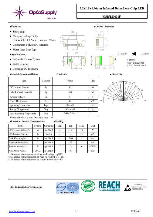
13.2x 1.6 x 1.96m m I n f r a r e d D o m e L e n s C h i p L E DOSI5120631F■Features■Outline Dimension● Single chip● Compact package outline(L x W x T) of 3.2mm x 1.6mm x1.96mm ● Compatible to IR reflow soldering. ● Water Clear Lens Type ■Applications● Automatic Control System ● Photo Detector ● Computer I/O Peripheral■Absolute Maximum Rating (Ta=25℃)■DirectivityItemSymbol Value Unit 0.530°90°60°000.530°60°90°11DC Forward Current I F 30 mA Pulse Forward Current# I FP 100 mA Reverse V oltage V R 5 V Power Dissipation P D 48 mW Operating Temperature Topr -30 ~ +85 ℃ Storage Temperature Tstg -40~ +100 ℃ Lead Soldering TemperatureTsol260℃/10sec- #Pulse width Max 0.1ms, Duty ratio max 1/10■Electrical -Optical Characteristics (Ta=25℃)ItemSymbol Condition Min. Typ. Max. Unit DC Forward V oltage*1 V F I F =20mA - 1.2 1.6V DC Reverse Current I R VR=5V - - 10µA Peak Wavelength*2 λp I F =20mA - 940 - nm Transmit Bandwidth λ I F =20mA - 45 - nm Radiant Intensity*3IeI F =20mA1.53 6 mW/Sr 50% Power Angle 2θ1/2 I F =20mA - 30-deg*1 Tolerance of measurements of forward voltage is +0.1V *2 Tolerance of measurements of Peak wavelength is +1nm *3 Tolerance of measurements of radiant intensity is +15%LED & Application TechnologiesUnit:mm 1. Cathode 2. AnodeTolerance:㊣ 0.10mm unless otherwise noted1 22■ Soldering ConditionsReflow SolderingHand SolderingPre-Heat 180 ~ 200°C Temperature Soldering time350°C Max. 3 sec. Max. (one time only)Pre-Heat Time 120 sec. Max. Peak temperature 260°C Max. Dipping Time10 sec. Max.ConditionRefer to Temperature-profile• Reflow Soldering Condition(Lead-free Solder)*Recommended soldering conditions vary according to the type of LED*Although the recommended soldering conditions are specified in the above table, reflow, or hand soldering at the lowest possible temperature is desirable for the LEDs.*A rapid-rate process is not recommended for cooling the LEDs down from the peak temperature. •All SMD LED products are pb-free soldering available.• Occasionally there is a brightness decrease caused by the influence of heat or ambient atmosphere during air reflow. It is recommended that the User use the nitrogen reflow method.• Repairing should not be done after the LEDs have been soldered. When repairing is unavoidable adouble-head solderingironshould be used. It should be confirmed beforehand whether the characteristics of the LEDs will or will not be damaged by repairing. • Reflow soldering should not be done more than two times. • When soldering, do not put stress on the LEDs during heating. • After soldering, do not warp the circuit board.LED & Application Technologies3■ Cautions:1. After open the package, the LED ´s floor life is 4 Weeks under 30℃ or less and 60%RH or less(MSL:2a).2. Heat generation must be taken into design consideration when using the LED.3. Power must be applied resistors for protection, over current would be caused the optic damage to the devices and wavelength shift.4. Manual tip solder may cause the damage to Chip devices, so advised that heat of iron should be lower than 15W with temperature control under 5 seconds at 230-260 deg. C. ( The device would be got damage in re working process, recommended under 5 seconds at 230-260 deg. C)5. All equipment and machinery must be properly grounded. It is recommended to use a wristband or anti-electrostatic glove when handing the LED.6. Use IPA as a solvent for cleaning the LED. The other solvent may dissolve the LED package and the epoxy, Ultrasonic cleaning should not be done.7. Damaged LED will show unusual characteristics such as leak current remarkably increase, turn-on voltage becomes lower and the LED get unlight at low current.LED & Application Technologies。
- 1、下载文档前请自行甄别文档内容的完整性,平台不提供额外的编辑、内容补充、找答案等附加服务。
- 2、"仅部分预览"的文档,不可在线预览部分如存在完整性等问题,可反馈申请退款(可完整预览的文档不适用该条件!)。
- 3、如文档侵犯您的权益,请联系客服反馈,我们会尽快为您处理(人工客服工作时间:9:00-18:30)。
3、应用:
DVD、TV、机顶盒、风扇等。
4、极限参数:(Ta=25℃)
Parameter
Symbol
Ratings
Unit
Supply Voltage
VCC
0.3—6
V
Operating Temperature
Topr
-25— +85
℃
Storage Temperature
6、特性曲线:
红外接收器IRM13Worldwide
6、测试波形:
7、电原理图:
8、应用电路:
红外接收器IRM138HWorldwide
9、尺寸:
红外接收器IRM138HWorldwide
1、描述:
IRM138H内含高速PIN光电二极管和全制程前置放大IC,采用内屏蔽封装,在红外遥控系统中作为接收器使用。
2、主要特性:
*模块封装,体积小巧;
*工作电压,4.5-5.5V;
*高灵敏度,抗光、电磁干扰能力强;
*最远工作距离30米;
*输出匹配TTL、CMOS电平,低电平有效;
RPU
30/40
KΩ
输出电流
IOCL
8
mA
接收距离
L
15
20
30
M
接收角度
θ1/2
+/-45
Deg
载波频率
f0
38
KHZ
BMP宽度
fBW
-3Db Bandwidth
f0-1.5
f0
f0+1.5
kHz
低电平输出
Vin=0V Vcc=5V
0.25
V
高电平输出
VOH
Vcc=5V
VCC-0.25
VCC
V
红外接收器IRM138HWorldwide
Tstg
-40 —— +125
℃
Soldering Temperature
Tsol
260(5S)
℃
5、光电参数:(T=25℃VCC=5Vf0=38KHZ)
参数
符号
测试条件
Min
Type
Max
单位
工作电压
VCC
4.5
5.0
5.5
V
工作电流
Icc
1.0
mA
静态电流
Ice
无信号输入时
0.8
1.5
mA
内部上拉电阻