H3C交换机板卡及模块PPT
H3C-ppt-visio-vss-华三网络设备模板素材图库

NE20
NE16/08 NE40
AR46
AR28
AR18
NE80
R3600E
R2500E
R2600E
R1700
3
具象产品图标-交换机
MA5200
S6500 S8500
S5000
S3500
S8000
S3000
S2000
S1000
4
具象产品图标-交换机
此处定义主要针对印刷品,PPT中规则可适当灵活
制图规范-图标排列
此处定义主要针对印刷品,PPT中规则可适当灵活
制图规范-范例
网络拓扑图
制图规范-范例
网络拓扑图
S3026 S3050 S3050 S3026 S8016 S8016 S3050 S3026 S3050
审计署
S3026 S3050
VLAN201 VLAN301
S2026 S2026
VLAN301 VLAN201
制图规范-范例
网络拓扑图
R3680E NE40
总部信息网络中心
E100
上市分公司 NE08E
R3680E
DDN/SDH/FR
DDN/SDH/FR
R3680E
R3680E R2631E
PSTN/ ISDN
PSTN/ISDN
华为3Com图标库2004版
本资料由-大学生创业|创业|创业网/提供资料 在线代理|网页代理|代理网页| 减肥药排行榜|淘宝最好的减肥药|什么减肥药效果最好|减肥瘦身药|
图标库目录
制图规范-绘图软件
以下内容主要针对资料设计供应商。
很实用的H3C交换机入门PPT

目录
• H3C交换机简介 • H3C交换机基本配置 • H3C交换机高级配置 • H3C交换机维护与管理 • H3C交换机应用场景与案例分析
01
H3C交换机简介
H3C公司简介
成立时间
H3C成立于XXXX年,是一家专注 于网络通信设备研发、生产和销 售的企业。
总部位置
H3C总部位于中国杭州,并在全球 多个国家和地区设有分支机构。
在命令行界面中,可以使用各种命令 来配置和管理交换机的各种功能。
交换机的配置模式
交换机的配置模式是进行各种配置操 作的前提,通过输入特定的命令进入 相应的配置模式。
在配置模式下,可以对交换机的各种 参数进行设置和修改,如VLAN、IP地 址等。
交换机的VLAN配置
VLAN(虚拟局域网)是用于将网络划分为多个逻辑子网的一种技术,可以提高网络的安全性和管理性。
05
H3C交换机应用场景与 案例分析
企业网中的应用场景
企业网是H3C交换机的主要应用 场景之一,涉及到园区网、分支
机构、数据中心等多个层面。
在企业网中,H3C交换机提供稳 定可靠的数据传输,支持多种接 入方式,满足企业日常办公、生
产、监控等需求。
案例分析:某大型企业采用H3C 交换机构建企业园区网,实现总 部与分支机构的互联互通,提高
信息,提高网络的灵活性和可靠性。
配置VLAN间路由
03
通过配置VLAN间路由,可以实现不同VLAN之间的通信,满足
不同部门或业务需求。
交换机的堆叠与集群配置
配置堆叠
通过将多台交换机连接在一起形成一个逻辑单元,可以提高网络的扩展性和可 靠性。
配置集群
交换机集群技术可以将多台交换机虚拟化为一台逻辑设备,简化网络管理和配 置。
H3C交换机板卡及模块解读

S过外接 波分复用器,将不同波长的光信号 复合在一起,通过一根光纤进行传 输,从而节约光 纤资源。同时,接 收端需要使用波分解复用器对复合 光信号进行分解。 适用:36 51 56 75 75E 95
对外型号
SFP-GE-LH70-SM1470-CW SFP-GE-LH70-SM1490-CW SFP-GE-LH70-SM1510-CW SFP-GE-LH70-SM1530-CW SFP-GE-LH70-SM1550-CW SFP-GE-LH70-SM1570-CW SFP-GE-LH70-SM1590-CW SFP-GE-LH70-SM1610-CW
接口类型 SC 接口 SC 接口
XENPAK CX4 电口模块
-
10GE 电口 连接器
光模块的传输距离分为短距、中距和长距三种。一般认为 2km 及以下的为短距离,10~20km 的为中距离,30km、 40km 及以上的为长 距离。中心波长指光信号传输所使用的 光波段。 目前常用的光模块的中心波长主要有三种:850nm 波段、 1310nm 波段以及 1550nm 波段。 850nm 波段:多用于短距离传输 1310nm 和 1550nm 波段:多用于中长距离传输
LC 接口
可插拔模块类型 XENPAK(10 Gigabit Ethernet Transceiver Package, 万兆以太网 接 口收发器 集合封装) 模块 XENPAK 光模块 XENPAK LX4 光模块
说明 光转发器(Transponder),可热插 拔 光转发器(Transponder),采用 CWDM 技术,可将光 信号分为 4 路在一根光纤中传输,可热插 拔
2000
< 300 m
单芯SPF光模块-BIDI
h3c全系列交换机介绍 PPT

课程目标
学习完本课程,您应该能够:
了解并掌握H3C 交换机 产品特点 了解如何引导交换机需求及H3C 交换
机方案 了解并掌握H3C竞争优势
目录
H3C 交换机产品
概述 高端交换机 千兆交换机 百兆交换机
交换机 方案部署 友商竞争分析一览表
H3C交换机发展之路
性价比最高 同样性能价格仅为思科50%左右
千兆接入价格低于思科百兆
H3C 全系列千兆交换机产品线简介
应用场景:
S5800/S5810/S5820X系列
➢1000-2000人规模园区网汇聚 ➢500~800人中型企业核心
➢数据中心网络
S5500-EI系列
S5600系列
应用场景: ➢500~1000人规模园区网汇聚 ➢300~500人中型企业核心 ➢数据中心网络
应用场景: ➢300~500人规模园区汇聚 ➢300人以内小型企业核心
S5100-EI系列
S5100-SI系列
S5500-SI系列
应用场景: ➢智能安全千兆接入 ➢网吧/办公室小型核心
S5800/S5810/S5820X系列产品一览
产品定位一:数据中心接入
千兆服务器 (End of Row)
千兆服务器 (Top of Rack)
H3C数据中心交换机产品
核心与汇聚
H3C S7500E系列
H3C S9500E系列
H3C S12500系列
机架与接入
H3C S5600系列
H3C S5500系列
H3C S5800/S5810/S5820X系列
H3C LAN交换机产品
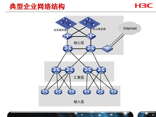
核心路由 交换机
汇聚交换机
智能二层/三层 交换机
H3C网络产品销售培训资料PPT(20张)

5、世上最美好的事是:我已经长大,父母还未老;我有能力报答,父母仍然健康。
•
6、没什么可怕的,大家都一样,在试探中不断前行。
•
7、时间就像一张网,你撒在哪里,你的收获就在哪里。纽扣第一颗就扣错了,可你扣到最后一颗才发现。有些事一开始就是错的,可只有到最后才不得不承认。
•
8、世上的事,只要肯用心去学,没有一件是太晚的。要始终保持敬畏之心,对阳光,对美,对痛楚。
主开发的无管理以太网交换产品,提供8个符 合IEEE802.3u标准的10/100M自适应以太网接 口,所有端口均支持全线速无阻塞交换以及端 口自动翻转功能。Aolynk S1008A-G交换机采 用桌面型塑胶壳设计。
S1008A-V 桌面型交换机
产品概述
Aolynk S1008A-V桌面型交换机是H3C公司自主 开发的无管理以太网交换产品,提供8个符合 IEEE802.3u标准的10/100M自适应以太网接口 ,所有端口均支持全线速无阻塞交换以及端口 自动翻转功能,1~7端口支持端口隔离。 Aolynk S1008A-V交换机采用桌面型塑胶壳设
计。
S1008A 桌面型交换机
产品概述 Aolynk S1008A桌面型交换机是H3C公司自主
开发的无管理以太网交换产品,提供8个符合 IEEE802.3u标准的10/100M自适应以太网接口 ,所有端口均支持全线速无阻塞交换以及端口 自动翻转功能。Aolynk S1008A交换机采用桌 面型塑胶壳设计。
企业级路由器
ER3100 ER3200 ER3260 ER5100 ER5200
网吧专用型
ER6300 ER8300
H3C网络产品—方案篇
网吧典型配置方案 普教校园网解决方案 中小企业网解决方案
H3C负载均衡交换机介绍V12精品PPT课件

7
面临的问题 H3C负载均衡交换机 典型组网应用
8
H3C负载均衡交换机系列
S7506E-V S7510E
S7506E S7503E
S7510E
ACE5000
业务槽位 L4吞吐量 L7吞吐量 其他选配模块
17
全局负载均衡
北京
50ms
深圳
100ms 150ms
杭州
✓通过对链路距离、响应时间快慢以及服务器健康状态检测,选择最佳路径。 ✓支持DNS重定向、HTTP重定向、非对称三角转发等多种全局负载均衡技术。
18
完善的网络协议支持
✓支持各种网络层协议: VLAN、ARP、策略路由等 ✓支持各种路由协议: 静态路由、RIP、OSPF、BGP等 ✓全面的NAT支持: NAT、PAT、双向NAT、静态NAT等 ✓支持IPV4/IPV6
来处理 。
12
全面的健康检测技术
H3C负载均衡交换机
TCP
TCP
Server 1
Server 2
支持多种健康检测技术:
✓ICMP ✓TCP ✓FTP ✓HTTP ✓HTTPS/SSL ✓POP3 ✓SMTP ✓DNS ✓RADIUS ✓其他
H3C专利NQA(网络质量分析)技术, 高效、实时的进行网络性能探测!
15
SSL加速
SSL加密报文SSL加密报文
安安全全链链接接 数数据据解加密密
TCP/HTTP
Internet
用户
SSL加速(优化)流程:
H3C负载均衡交换机
服务器
1. 负载均衡交换机与客户端建立安全连接。 2. 客户端与负载均衡交换机进行SSL会话,进行加密数据传输。 3. 负载均衡交换机处理SSL协议,并且与服务器进行优化后的
【培训】H3C培训PPT课件

ISSUE 1.0
.
杭州华三通信技术有限公司 版权所有,未经授权不得使用与传播
欢迎你来访 谢谢下载 1
目录
第一章 VLAN原理及基本配置 第二章 STP原理及基本配置 第三章 ACL原理及基本配置 第四章 设备管理基本配置 第五章 常用维护方法和命令
.
欢迎你来访 谢谢下载 2
• Hybrid link:允许多个VLAN的tagged数据 流和多个VLAN的untagged数据流通过。
• Hybrid端口可以允许多个VLAN的报文发送时不携带标签,而Trunk端 口只允许缺省VLAN的报文发送时不携带标签。
• 三种类型的端口可以共存在一台设备上
.
欢迎你来访 谢谢下载 6
Access Link和Trunk Link
Host B
172.16.1.2/24
Switch
Vlan-int1 172.16.1.1/24 172.16.2.1/24 sub
172.16.2.2/24
172.16.2.0/24
Host A
.
欢迎你来访 谢谢下载 15
VLAN配置举例
Server2
Server1
SwitchA
Eth1/0/2
port Ethernet 2/0/1
在VLAN中删除端口.
undo port Ethernet 2/0/1
将端口加入VLAN
port access vlan 100 (1-4094) 将端口脱离VLAN
undo port access vlan 100 (1-4094) 显示VLAN信息
display vlan VLAN ID (1-4094)
三层交换机培训文档PPT课件

技术基础-文件系统
文件管理常用命令: Dir-列目录
Switch# dir
Directory of /:
1 Switch.bin 2006
<FILE>
2 startup-config <FILE> 2006
free space 12288000
Switch#
4377940 MON OCT 09 15:24:38 1734 WED NOV 08 23:04:13
8
技术基础-文件系统
交换机系统文件的命名规则 ROS系统文件,必须命名为*.bin 注:当Flash中保存有多个bin文件时,系统默认使用第1 个bin文件引导,也可用boot system flash命令指定引导 文件
配置文件,必须命名为startup-config
9
10
技术基础-文件系统
文件管理常用命令:
write- 生成或更新startup-config文件 Delete - 删除startup-config文件 Delete <Filename> - 删除指定文件 rename <Filename> - 文件改名 Copy <Source> <Destination> - 复制文件 Format - 格式化flash卡
Switch>en
//显示所有以en开头的命令 -- Turn on privileged commands -- Help message in English
Switch_config#interface ? //显示interface命令的子命令
FastEthernet -- FastEthernet interface
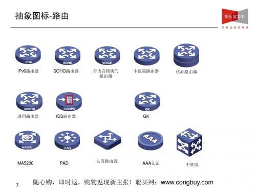
《H3C 全系列产品图标库(ppt 47页)》

WWW 服务
Email 服务
文件服务
路由器与交换机
24口交换机
48口交换机
通用交换机
通用路由器
HBA卡
FC HBA卡
TOE HBA卡
FC HBA卡竖
TOE HBA卡 竖
磁盘系列产品图标
磁盘机柜
磁盘抽屉
磁盘
磁盘阵列控制器
友商存储产品
IBM存储产品(高端)IBM存储产品(中低端)
DELL 存储产品
IPS
有防火墙特性的 集成SecBlade
集成SecBlade模块的交换机
7
抽象图标-无线
网桥
WAP
PSE
DTU
CSU
DCE
CAMS
共享磁带库
摄像机
VRP通用路由平台( 操作系统)
6
抽象图标-语音视讯
一体化视讯终端
分体式视讯终端
电视墙
呼叫控制服务器 (XE200/2000)
语音业务服务器 (XE7000)
接入服务器
集线器
4
抽象图标-安全
安全网关VPN
计费网关
入侵检测系统
无线网卡
防火墙
语音网关
语音服务器 AP 大功率AP 无线网桥 网络电话系统 深度测试防火墙
PBX
DSLAM
ISDN(抽象)
Modem(抽象)
Software_comware
5
抽象图标-安全
SecBlade防火墙模块
SecBladeVPN模块
12月新增图标
Neocean 低端产品通用图标
通用存储
UPS
Network-management
Xlog MA5200
H3C交换机板卡及模块

SFP-BIDI GEPON OLT 光模块
• BIDI GEPON OLT 光模块是一种专用于 EPON OLT 端 设备的千兆 SFP 模块。需要注意的是通过 SFP-GEPX10-D-SM1490-A 模块传输 的光信号只能用于 10 公 里版本的 ONU 设备。
• 记住:主要是用于EPON网络环境中 • 适用:支持SFP模块的绝大多数交换机
10.31 9.95~10.7 10.31 10.31 9.95~10.7
10G 电口模块简介
• XENPAK CX4 电口模块 • XENPAK-CX4-15m。传输
速率达 12.5Gb/s
SFP堆叠模块
电源模块
• 9500 7500E • 不标配电源,都需要至少配1块 • 7500 • S7506R/S7506电源2+1冗余,S7503电源
接口连接器 类型
RJ-45
适用:支持SFP模块的绝大多数交换机
GBIC-光、电模块
XFP光模块
XFP万兆光模块,接口类型为LC 对于62.5um MMF w/ 160MHz*km光纤, 最大传输距离26M; 对于50um MMF w/ 500MHz*km光纤, 最大传输距离82M; 对于50um MMF w/ 2000MHz*km光纤, 最大传输距离300M;
中心波长 1470nm 1490nm 1510nm 1530nm 1550nm 1570nm 1590nm 1610nm
传输距离 70km
Data Rate 1250Mb/s
SFP-千兆电接口模块
对外型号 SFP-GE-T
传输距离 100m
Data Rate 1250Mb/s
外接线缆类 型
5 类非屏蔽 双绞线
H3C交换机安装手册【板卡】

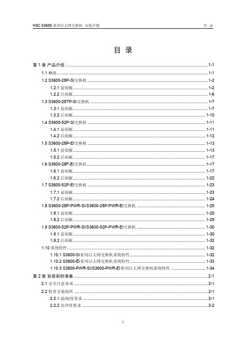
Table of ContentsChapter 2 LPU Modules................................................................................................................2-12.1 Overview............................................................................................................................2-12.2 XP2 Module.......................................................................................................................2-12.2.1 Specifications..........................................................................................................2-12.2.2 Panel and LEDs......................................................................................................2-22.2.3 Matching Cable.......................................................................................................2-32.3 XP4/XP4T Module.............................................................................................................2-32.3.1 Specifications..........................................................................................................2-32.3.2 Panel and LEDs......................................................................................................2-42.3.3 Matching Cable.......................................................................................................2-42.4 XK1 Module.......................................................................................................................2-42.4.1 Specifications..........................................................................................................2-42.4.2 Panel and LEDs......................................................................................................2-52.4.3 Matching Cable.......................................................................................................2-62.5 GP12 Module.....................................................................................................................2-62.5.1 Specifications..........................................................................................................2-62.5.2 Panel and LEDs......................................................................................................2-72.5.3 Matching Cable.......................................................................................................2-72.6 GP24 Module.....................................................................................................................2-82.6.1 Specifications..........................................................................................................2-82.6.2 Panel and LEDs......................................................................................................2-92.6.3 Matching Cable.......................................................................................................2-92.7 GP48 Module...................................................................................................................2-102.7.1 Specifications........................................................................................................2-102.7.2 Panel and LEDs....................................................................................................2-102.7.3 Matching Cable.....................................................................................................2-112.8 FP20 Module....................................................................................................................2-112.8.1 Specifications........................................................................................................2-112.8.2 Panel and LEDs....................................................................................................2-112.8.3 Matching Cable.....................................................................................................2-122.9 GT8P Module...................................................................................................................2-122.9.1 Specifications........................................................................................................2-122.9.2 Panel and LEDs....................................................................................................2-132.9.3 Matching Cable.....................................................................................................2-142.10 F32G Module.................................................................................................................2-142.10.1 Specifications......................................................................................................2-142.10.2 Panel and LEDs..................................................................................................2-152.10.3 Matching Cable...................................................................................................2-162.11 GT24 Module.................................................................................................................2-172.11.1 Specifications......................................................................................................2-172.11.2 Panel and LEDs..................................................................................................2-182.11.3 Matching Cable...................................................................................................2-18 2.12 GV48 Module.................................................................................................................2-192.12.1 Specifications......................................................................................................2-192.12.2 Panel and LEDs..................................................................................................2-202.12.3 Matching Cable...................................................................................................2-20 2.13 FT48 Module..................................................................................................................2-202.13.1 Specifications......................................................................................................2-202.13.2 Panel and LEDs..................................................................................................2-212.13.3 Matching Cable...................................................................................................2-21 2.14 P4G8 Module.................................................................................................................2-222.14.1 Specifications......................................................................................................2-222.14.2 Panel and LEDs..................................................................................................2-232.14.3 Matching Cable...................................................................................................2-24 2.15 SP4 Module...................................................................................................................2-242.15.1 Specifications......................................................................................................2-242.15.2 Panel and LEDs..................................................................................................2-252.15.3 Matching Cable...................................................................................................2-25 2.16 UP1 Module...................................................................................................................2-262.16.1 Specifications......................................................................................................2-262.16.2 Panel and LEDs..................................................................................................2-272.16.3 Matching Cable...................................................................................................2-27 2.17 RGP2 Module................................................................................................................2-272.17.1 Specifications......................................................................................................2-272.17.2 Panel and LEDs..................................................................................................2-282.17.3 Matching Cable...................................................................................................2-28 2.18 RGP4 Module................................................................................................................2-292.18.1 Specifications......................................................................................................2-292.18.2 Panel and LEDs..................................................................................................2-292.18.3 Matching Cable...................................................................................................2-30 2.19 VP2 Module...................................................................................................................2-302.19.1 Specifications......................................................................................................2-302.19.2 Panel and LEDs..................................................................................................2-312.19.3 Matching Cable...................................................................................................2-31 2.20 RSP2 Module.................................................................................................................2-312.20.1 Specifications......................................................................................................2-312.20.2 Panel and LEDs..................................................................................................2-322.20.3 Matching Cable...................................................................................................2-32Chapter 2 LPU Modules2.1 OverviewThe S9500 series are modular switches that are designed following industry standards.The series can be equipped with these types of LPU modules:z XP2 module: provides two 10GEBase-R XFP/LC/10GEBase-W XFP/LC optical portsz XP4 module: provides four 10GE XFP/LC optical ports (1:2 convergence)z XP4T module: provides four wire-speed 10GE XFP/LC optical portsz XK1 module: provides one 10GE XENPAK/SC optical/electrical portz GP12 module: provides 12 × 1000 Mbps SFP/LC electrical/optical portsz GP24 module: provides 24 × 1000 Mbps SFP/LC optical portsz GP48 module: provides 48 × 1000 Mbps SFP/LC optical portsz FP20 module: provides 20 × 100 Mbps SFP/LC optical portsz GT8P module: provides four 1000 Mbps SFP/LC optical ports and eight 10/100/1000 Mbps auto-sensing RJ-45 portsz F32G module: provides four 1000 Mbps SFP/LC optical ports and 32 × 10/100 Mbps auto-sensing RJ-45 portsz GT24 module: provides 24 × 10/100/1000 Mbps auto-sensing RJ-45 portsz GV48 module: provides 48 × 10/100/1000 Mbps PoE-capable auto-sensing RJ-45 portsz FT48 module: provides 48 × 10/100 Mbps portsz P4G8 module: provides eight 1000 Mbps SFP/LC optical ports and four 155 Mbps SFP/LC POS optical portsz SP4 module: provides four OC-48c SFP/LC POS optical portsz UP1 module: provides one OC-192c XFP/LC POS optical portz RGP2 module: provides two 1000 Mbps SFP/LC RPR optical ports, and eight 1000 Mbps SFP/LC Ethernet optical portsz RPG4 module: provides four 1000 Mbps SFP/LC RPR optical ports, and eight 1000 Mbps SFP/LC Ethernet optical portsz VP2 module: provides two OC-192c XFP/LC RPR optical portsz RSP2 module: provides two OC-48c SFP/LC RPR optical ports2.2 XP2 Module2.2.1 SpecificationsThe XP2 module provides two 10GEBase-R XFP/LC/10GEBase-W XFP/LC opticalports.Table 2-1 XP2 module specificationsLED Status MeaningOFF No link is present.LINKGreen A link is present.OFF No packets are transmitted/received on the port. ACTOrange blinking Packets are transmitted/received on the port.2.2.3 Matching CableTable 2-3 describes the XFP optical modules available to the 10 Gbps XFP optical portson the XP2 module and their matching cables, which you can select as required.Table 2-3 Optical interface modules available for the XP2 moduleSFP moduleCentralwavelengthConnectorMatchingcableMax transmissiondistance10GBase-SR /SW-XFP 850 nm50/125 µmmultimodeopticalfiber26 m (85.3 ft) for the62.5 µm MMF w/ 160MHz*km cable;82 m (269.0 ft) for the50 µm MMF w/ 500MHz*km cable;300 m (984.3 ft) forthe 50 µm MMF w/2,000 MHz*km cable10GBase-LR/ LW-XFP 1,310 nm9/125 µmsingle-mode opticalfiber10 km (6.2 miles)40 km (24.9 miles)10GBase-ER /EW-XFP 1,550 nmLC9/125 µmsingle-mode opticalfiber 80 km (49.7 miles)2.3 XP4/XP4T Module2.3.1 SpecificationsThe XP4 non-line-speed/XP4T line speed module provides four 10GE XFP/LC opticalports.Table 2-4 XP4 non-line-speed/XP4T line speed module specificationsItem SpecificationCPU MPC8245Boot ROM 512 KBSDRAM 256MB Physical dimensions (W × D) 366.7 × 340 mm (14.4 × 13.4 in.)Number of ports FourSupported card suffix XP4: CA, B XP4T: DBItemSpecification158 W (for the XP4 with a suffix of CA) 155 W (for the XP4 with a suffix of B) Maximum power consumption (with bottom plate)178 W (for the XP4T with a suffix of DB)Connector XFP/LC Rate 10 Gbps2.3.2 Panel and LEDs(1)(2)(1): Optical port(2): Port LEDFigure 2-2 XP4 non-line-speed/XP4T line speed module panel The XP4/XP4T module has two LEDs for each optical port on its panel. Table 2-5 1000 Mbps optical port LEDs on the XP4/XP4T moduleLED Status MeaningOFF No link is present. LINKGreen A link is present.OFFNo packets are transmitted/received on the port. ACT Orange blinkingPackets are transmitted/received on the port.2.3.3 Matching CableFor details about XFP optical modules available to the XFP optical ports on the XP4 non-wire-speed or XP4T wire-speed module and their matching cables, see Table 2-3.2.4 XK1 Module2.4.1 SpecificationsThe XK1 module provides one 10GE XENPAK/SC optical/electrical port.Table 2-6 XK1 module specificationsItem SpecificationCPU MPC8245Boot ROM 512 KBSDRAM 256MB Physical dimensions (W × D) 366.7 × 340 mm(14.4 × 13.4 in.)Suffix of supported card DB, CA, and B42 W (for cards with a suffix of DB)Maximum power consumption44 W (for cards with a suffix of CA)42 W (for cards with a suffix of B)Number of ports OneConnector XENPAK/SCGbps Rate 102.4.2 Panel and LEDs(1)(2)(1): Optical/electric port (2): Port LEDFigure 2-3 XK1 module panelThe XK1 module has two port LEDs for the 10GE port on its panel.Table 2-7 Port LEDs on the XK1 moduleLED Status MeaningOFF No link is present.LINKGreen ON A link is present.OFF No packets are transmitted/received on the port.ACTOrange blinking Packets are transmitted/received on the port.2.4.3 Matching CableTable 2-8 describes the XENPAK optical modules available to the 10GE XENPAK/SCoptical/electrical port on the XK1 module and their matching cables, which you canselect as required.Table 2-8 Interface modules available for the XK1 moduleSFP moduleCentralwavelengthConnectorMatchingcableMax transmissiondistance10GBASE-SR-XENPAK 850 nmMultimodeopticalfiber26 m (85.3 ft) for the62.5 µm MMF w/160 MHz*km cable;82 m (269.0 ft) forthe 50 µm MMF w/500 MHz*km cable;300 m (984.3 ft) forthe 50 µm MMF w/2,000 MHz*kmcable10GBASE-LR-XENPAK1,310 nm 10 km (6 mi)10GBASE-ER-XENPAK1,550 nm 40 km (25 mi)XENPAK-LH80-SM1550 1,550 nmSCSingle-mode opticalfiber80 km (50 mi)2.5 GP12 Module2.5.1 SpecificationsThe GP12 module provides 12 × 1000 Mbps SFP/LC optical ports.Table 2-9 GP12 module specificationsItem SpecificationCPU MPC8245Boot ROM` 512 KBSDRAM 256MB Physical dimensions (W × D) 366.7 × 340 mm (14.4 × 13.4 in.)Suffix of supported card DB, CA, and BItem Specification59 W (for cards with a suffix of DB)Maximum power consumption61 W (for cards with a suffix of CA)59 W (for cards with a suffix of B)Number of ports 12Connector SFP/LCMbps Rate 1,0002.5.2 Panel and LEDs(1)(2)(1): Optical/electric port (2): Port LEDFigure 2-4 GP12 module panelThe GP12 module has two LEDs for each port on its panel.Table 2-10 Port LEDs on the GP12 moduleLED Status MeaningOFF No link is present.LINKGreen ON A link is present.OFF No packets are transmitted/received on the port.ACTOrange blinking Packets are transmitted/received on the port.2.5.3 Matching CableTable 2-11 describes the SFP optical modules available to the SFP optical ports on theGP12 module and their matching cables, which you can select as required.Table 2-11 Available SFP optical modules SFP moduleCentral wavelengthConnectorMatching cable Maxtransmission distance 50/125 µm multimode optical fiber 550 m (1804 ft)1000BASE-S X-SFP850 nm62.5/125 µm multimode optical fiber275 m (902 ft)1000BASE-L X-SFP 10 km (6 mi)1000BASE-L H-SFP 1,310 nm1000BASE-Z X-LR- SFP 40 km (25 mi)1000BASE-Z X-VR-SFP 70 km (43 mi) 1000BASE-Z X-UR-SFP 1,550 nmLC9/125 µm single-mode optical fiber100 km (62 mi)2.6 GP24 Module2.6.1 SpecificationsThe GP24 module provides 24 × 1000 Mbps SFP/LC optical ports. Table 2-12 GP24 module specificationsItemSpecificationCPU MPC8245 Boot ROM512 KBSDRAM 256 MB/512 MB Physical dimensions (W × D) 366.7 × 340 mm (14.4 × 13.4 in.) Suffix of supported cardDB, CA, DC, CB, and BItem Specification95 W (for cards with a suffix of DB)97 W (for cards with a suffix of CA)97 W (for cards with a suffix of DC)Maximum power consumption98 W (for cards with a suffix of CB)95 W (for cards with a suffix of B)Number of ports 24Connector SFP/LCMbps Rate 1,0002.6.2 Panel and LEDs(1)(2)(1): Optical port (2): Port LEDFigure 2-5 GP24 module panelThe GP24 module has two LEDs for each 1000 Mbps optical port on its panel.Table 2-13 Port LEDs on the GP24 moduleLED Status MeaningOFF No link is present.LINKGreen ON A link is present.OFF No packets are transmitted/received on the port.ACTOrange blinking Packets are transmitted/received on the port.2.6.3 Matching CableYou can select appropriate SFP optical modules for the 1000 Mbps SFP optical portson the GP24 module according to your needs. For description of SFP optical modulesavailable to the SFP optical ports and their matching cables, see Table 2-11.2.7 GP48 Module2.7.1 SpecificationsThe GP48 module provides 48 × 1000 Mbps SFP/LC optical ports.Table 2-14 GP48 module specificationsItem SpecificationCPU MPC8245KB BootROM 512MB SDRAM 256Physical dimensions (W × D) 366.7 × 340 mm (14.4 × 13.4 in.)Suffix of supported card DBMaximum power consumption 100 WNumber of ports 48Connector SFP/LCMbps Rate 1,0002.7.2 Panel and LEDs(1): Optical port (2): Port LEDFigure 2-6 GP48 module panelThe GP48 module has one LED for each 1000 Mbps optical port on its panel.Table 2-15 Port LEDs on the GP48 moduleLED Status MeaningSolid on A link is present.LINK/ACTSolid off No link is present.Blinking The port is transmitting or receiving data.2.7.3 Matching CableYou can select appropriate SFP optical modules for the 1000 Mbps SFP/LC opticalports on the GP48 module accordingly to your needs. See Table 2-11 for available SFPoptical modules and their matching cables.2.8 FP20 Module2.8.1 SpecificationsThe FP20 module provides 20 × 100 Mbps SFP/LC optical ports.Table 2-16 FP20 module specificationsItem SpecificationCPU MPC8245Boot ROM 512 KBMB SDRAM 256Physical dimensions (W × D) 366.7 × 340 mm (14.4 × 13.4 in.)Suffix of supported card B and CA67 W (for cards with a suffix of B)Maximum power consumption69 W (for cards with a suffix of CA)Port 20Connector SFP/LCRate 100 Mbps full duplex2.8.2 Panel and LEDs(1)(2)(1): Optical port (2): Port LEDFigure 2-7 FP20 module panelThe FP20 module has two LEDs for each port on its panel.Table 2-17 Port LEDs on the FP20 moduleLED Status MeaningOFF No link is present. LINKGreen A link is present.OFFNo packets are transmitted/received on the port. ACT Orange blinkingPackets are transmitted/received on the port.2.8.3 Matching CableTable 2-18 describes the SFP optical modules available to the 100 Mbps SFP optical ports on the FP20 module, which you can select as required. Table 2-18 Available optical interface modules SFP moduleCentral wavelengthConnectorMatching cable Maxtransmission distance50/125 µm multimode optical fiber 100BASE-FX-MM-SFP62.5/125 µm multimode optical fiber2 km (1 mi)100BASE-FX-SM-SFP 15 km (9 mi)100BASE-FX-SM-LR-SFP 1,310 nm40 km (25 mi)100BASE-FX-SM-VR-SFP 1,550 nmLC9/125 µm single-mode optical fiber80 km (50 mi)2.9 GT8P Module2.9.1 SpecificationsThe GT8P module provides four 1,000 Mbps SFP/LC optical ports and eight 10/100/1,000 Mbps auto-sensing RJ-45 ports.Table 2-19 GT8P module specificationsItemSpecificationCPU MPC8245 Boot ROM512 KBSDRAM 256 MB Physical dimensions (W × D) 366.7 × 340 mm (14.4 × 13.4 in.) Suffix of supported card CA Maximum power consumption 57 WNumber of portsFour 1000 Mbps SFP/LC optical portsEight 10/100/1000 Mbps auto-sensingRJ-45 portsConnector SFP/LC, RJ-45Rate 1000 Mbps (SFP/LC optical ports)10/100/1,000 Mbps auto-sensing (RJ-45electrical ports)2.9.2 Panel and LEDs(1): RJ-45 port (2): 100 Mbps port LED (3): Optical port (4): 1000 Mbps port LEDFigure 2-8 GT8P module panelThe GT8P module has two port LEDs for each port on its panel. Table 2-20 Port LEDs on the GT8P moduleLED Status MeaningOFF No link is present. LINKGreen A link is present.OFFNo packets are transmitted/received on the port. ACT Orange blinkingPackets are transmitted/received on the port.2.9.3 Matching CableYou can select appropriate SFP optical modules for the 1000 Mbps SFP optical portsyou want to use on the GT8P module. See Table 2-11 for available SFP optical modulesand their matching cables.You can use RJ-45 connectors (as shown in Figure 2-9) and category-5 twisted pairsfor the 10/100/1000 Mbps electrical ports on the GT8P module. The maximumtransmission distance is 100 m (328.1 ft).PIN #8PIN #1Figure 2-9 RJ-45 connectorTable 2-21 Pin assignment of the RJ-45 GE connector10Base-T/100Base-T/1000Base-TXPin No.Signal Function1 MX_0+ Transmit and receive data.2 MX_0- Transmit and receive data.3 MX_1+ Transmit and receive data.4 MX_2+ Transmit and receive data.5 MX_2- Transmit and receive data.6 MX_1- Transmit and receive data.7 MX_3+ Transmit and receive data.8 MX_3- Transmit and receive data.2.10 F32G Module2.10.1 SpecificationsThe F32G module provides four 1000 Mbps SFP/LC optical ports and 32 × 10/100Mbps auto-sensing RJ-45 ports.Table 2-22 F32G module specificationsTable 2-23 1000 Mbps port LEDs on the F32G moduleLED Status MeaningOFF No link is present.LINKGreen ON A link is present.OFF No packets are transmitted/received on the port. ACTOrange blinking Packets are transmitted/received on the port.The F32G module has one LED for each 100 Mbps port on its panel.Table 2-24 100 Mbps port LEDs on the F32G moduleLED Status MeaningON A link is present on the port.LINK/ACTOFF No link is present on the port.Blinking Packets are transmitted/received on the port.2.10.3 Matching CableYou can select appropriate SFP optical modules for the 1000 Mbps SFP optical portson the F32G module accordingly. See Table 2-11 for available SFP optical modules andtheir matching cables.You can use RJ-45 connectors (as shown in Figure 2-11) and category-5 twisted pairsfor the 10/100 Mbps electrical ports on the F32G module. The maximum transmissiondistance is 100 m (328.1 ft).PIN #8PIN #1Figure 2-11 RJ-45 connectorTable 2-25 Pin assignment of the RJ-45 MDI connector10Base-T/100Base-TXPin No.Signal Functiondata.1 Tx+ Transmitdata.2 Tx- Transmitdata.3 Rx+ Receive4 Reserved —5 Reserved —6 Rx- Receivedata.7 Reserved —8 Reserved —Table 2-26 Pin assignment of the RJ-45 MDI-X connector10Base-T/100Base-TXPin No.Signal Functiondata.1 Rx+ Receive2 Rx- Receivedata.data.3 Tx+ Transmit4 Reserved —5 Reserved —data.6 Tx- Transmit7 Reserved —8 Reserved —Note:Tx = Transmit data; Rx = Receive data2.11 GT24 Module2.11.1 SpecificationsThe GT24 module provides 24 × 10/100/1000 Mbps auto-sensing RJ-45 ports.Table 2-27 GT24 module specificationsItem SpecificationCPU MPC8245Boot ROM 512 KBMB SDRAM 256Physical dimensions (W × D) 366.7 × 340 mm (14.4 × 13.4 in.)Suffix of supported card DB, CA, and B87 W (for cards with a suffix of DB)Maximum power consumption89 W (for cards with a suffix of CA)87 W (for cards with a suffix of B)Number of ports 24Connector RJ-45Item SpecificationMbps Rate 10/100/1,0002.11.2 Panel and LEDs(1)(2)(1): RJ-45 port (2): 100 Mbps port LEDFigure 2-12 GT24 module panelThe GT24 module has one LED for each port on its panel.Table 2-28 Port LEDs on the GT24 moduleLED Status MeaningON No link is present.LINK/ACTOFF A link is present.Blinking Packets are transmitted/received on the port.2.11.3 Matching CableYou can use RJ-45 connectors (as shown in Figure 2-13) and category-5 twisted pairsfor the GT24 module. The maximum transmission distance is 100 m (328.1 ft).PIN #8PIN #1Figure 2-13 RJ-45 connectorTable 2-29 Pin assignment of the RJ-45 GE connector10Base-T/100Base-T/1000Base-TXPin No.Signal Function1 MX_0+ Transmit and receive data.2 MX_0- Transmit and receive data.3 MX_1+ Transmit and receive data.4 MX_2+ Transmit and receive data.5 MX_2- Transmit and receive data.6 MX_1- Transmit and receive data.7 MX_3+ Transmit and receive data.8 MX_3- Transmit and receive data.2.12 GV48 Module2.12.1 SpecificationsThe GV48 module provides 48 × 10/100/1,000 Mbps auto-sensing PoE-capable RJ-45ports.Table 2-30 GV48 module specificationsItem SpecificationCPU MPC8245BootROM 512KBMB/256MB SDRAM 128Physical dimensions (W × D) 366.7 × 340 mm (14.4 × 13.4 in.)Suffix of supported card DBMaximum power consumption110 WNumber of ports 48Connector RJ-45Mbps Rate 10/100/1,000。
第1章h3c网络设备基本操作PPT课件

配置接口参数的视图
用户界面视图
配置登陆设备的各个用户属性的视图
各种视图之间的关系
interface命令 quit
接口视图
用户视图
以任意方式 登录命令行
system-view quit
系统视图
user-interface命令
用户界面视图
quit
router命令 quit
路由协议视图
vlan命令 quit
路由器与交换机的发展趋势
路由和交换的融合 多业务功能的融合
目录
路由器与交换机的作用与特点 H3C路由器与交换机介绍 H3C网络设备操作系统Comware
H3C路由器系列
H3C路由器示例
CF卡插槽
电源开关及插座 配置口(Console)
备份口(AUX)
多功能接口模 块(MIM) 智能接口 卡(SIC)
本章总结
路由器是利用三层IP地址信息进行报文转发的互 联设备
交换机是利用二层MAC信息进行数据帧交换的互 联设备
路由器、交换机的运行依赖的软件核心是网络设 备的操作系统
H3C Comware软件平台是H3C IP网络设备的核 心软件平台
命令行操作基础
ISSUE 1.0
日期: 杭州华三通信技术有限公司 版权所有,未经授权不得使用与传播
路由器的作用
RTB
RTD
PCA RTA
RTC
RTE
PCB
连接具有不同介质的链路
连接网络或子网,隔离广播
对数据报文执行寻路和转发
交换和维护路由信息
路由器的特点
主要工作在OSI模型的物理层、数据链路 层和网络层
根据网络层信息进行路由转发 提供丰富的接口类型 支持丰富的链路层协议 支持多种路由协议
华三(H3C)_STP原理和基本配置介绍PPT学习课件

根路径开销
SWA
1000M
Root 100M
Cost=10
Cost=20
1000M
Cost=30
10M SWB
100M
10M SWC
根路径开销( RootPathCost)是到达根的路径上所有链路开销(Cost) 的代数和
SWA
核心
SWB
[SWB]stp enable [SWB]stp priority 4096
SWC E1/0/1 接入用户
[SWC]stp enable [SWC]interface Ethernet 1/0/1 [SWC-Ethernet1/0/1] stp edgedport enable
SWC 32
物理段 B
STP的作用
ROOT
物理段 B
物理段 A
物理段 C
物理段 D
物理段 E
通过阻断冗余链路来消除桥接网络中可能存在的路径回环 当前路径发生故障时,激活冗余备份链路,恢复网络连通性
目录
生成树背景 STP RSTP MSTP 生成树协议的配置
实例ID
端口角色
端口状态
杭州华三通信技术有限公司
在某些情况下,端口进入转发状态的延时大大缩短,从而缩 短了网络最终达到拓扑稳定所需要的时间。
RSTP的改进
端口被选 为根端口
端口被选 为指定端 口
STP行为
RSTP行为
默认情况下,2倍的 Forwarding Delay的 时间延迟。
存在阻塞的备份根端口情况下, 仅有数毫秒延迟。
最新H3C交换机板卡及模块解析教学讲义PPT课件

数量范围 0-2 0-2 0-2 0-2 0-2 0-2
5600
项目描述 S5600功能模块——8端口千兆SFP转接板 S5600功能模块——1端口万兆XENPAK转接板 S5600功能模块——2端口万兆XFP光接口以太网模块 PoE功能的电源模块 S5600专用堆叠电缆
数量范围 0-1 0-1 0-1 0-1 0-2
接口连接器 类型
RJ-45
适用:支持SFP模块的绝大多数交换机
GBIC-光、电模块
XFP光模块
XFP万兆光模块,接口类型为LC 对于62.5um MMF w/ 160MHz*km光纤, 最大传输距离26M; 对于50um MMF w/ 500MHz*km光纤, 最大传输距离82M; 对于50um MMF w/ 2000MHz*km光纤, 最大传输距离300M;
SFP-GE-SX-MM850-A SFP-GE-LX-SM1310-A
SFP-STACK-Kit
SFP-GE-LX-SM1310-BIDI SFP-GE-LX-SM1490-BIDI
S3100-8TP-SI专用长挂耳 S3100-16TP-SI专用长挂耳
数量 0~2 0~2 0~2 0~2 0~1
1000BASE-LX-SFP_BIDI
1000BASE-LX-SFP_CWDM 1000Base-T-AN-SFP 1000BASE-T-SFP_STACK
中心波长
SFP模块 提供的用 户接口连 接器类型
接口线缆规 格及最大传 输距离
850nm
1310nm
1550nm
1310/149 0nm
1490/131 0nm
-
RJ-45 接口
GBIC(Gigabit
很实用的H3C交换机入门PPT

55-18 1
10.63.32.2 2 2 Invalid GigabitEthernet2/1 00-e0-fc-00-
55-18 1
基本概念介绍-三种Link
Access access类型的端口只能属于1个VLAN,从access口出来的数据帧不带VLAN标签,一般用于连接计算 机。
Trunk trunk类型的端口可以属于多个VLAN,可以接收和发送多个VLAN的数据帧,一般用于交换机之间的 连 接。
MAC ADDR VLAN ID STATE
PORT INDEX
AGING
TIME
00e0-fc09-bcf9 1
Learned
Ethernet0/1
AGING
00e0-fc20-ea3e 1
Learned
Ethernet0/1
AGING
0008-740c-6bb8 101
Learned
Ethernet0/1
第2章 以太网交换机配置
第3章 交换机维护
VLAN的基本概念
Virtual Local Area Networks,虚拟局域网。 是将位
于不同网段的上用户和服务器从逻辑上划分成 的终端
站组。 VLAN的出发点:
限制广播包 安全性 减少移动和改变的代价 虚拟工作组
二层交换原理
二层交换的依据是MAC转发表,MAC转发表项为:目的MAC和出端口的映射。 MAC
R
Access Link: 只属于一个VLAN, 不关心VLAN的成员都是 谁
基本概念介绍-PVID、
VLAN ID 在VLAN技术中,PVID是端口的一个重要概念:
“PVID”是“Port VLAN ID”的缩写,是“端口缺省VLAN ID”的意思,即一个端口缺
h3c全系列交换机介绍 PPT

适合城域网汇聚、大型网络汇聚、中 小型网络核心和大中型配线间
6业务插槽垂直机箱
针对防火、防震和散热等方面进行了 专业设计,适合大型数据中心和运营 商中心机房
10业务插槽机箱
适合高密度配线间和大型网络汇聚
H3C S7500E 产品一览
S7503E S7502E
S7506E-V S7506E
卖点总结
– 各项硬件指标业内领先 – 96G高带宽IRF智能堆叠 – 品牌好,用户认可度高
应用场景
– 大型企业IPv4网络汇聚层; – 数据中心网络服务器连接;
S5500EI 增强型IPv6万兆交换机
H3C-S5500-28C-EI/PWR
H3C-S5500-52C-EI/PWR
H3C-S5500-28F-EI
H3C S5800系列模块一览
300W电源模块(AC/DC)
配置说明:S5810-50S随机已有一个模块,根据需要选配冗余的模块; S5800-28F, S5800-60C-PWR, S5810-50S, S5820X-28S, S5820X28C随机不带模块, 根据至少配置一个模块,再根据需要选配冗余的 模块
H3C S5800-56C/S5800-56C-PWR(前面板)
RPS冗余接口 220V交流接口
端口扩展槽
H3C S5800-56C(后面板)
H3C S5800系列主机一览
内置Console和USB口
端口扩展槽 24个100/1000M SFP
4个1/10G SFP+
H3C S5800-32F(前面板)
2009年
H3C推出面向数据中
心的核心和接入交换
2008年
机
H3C交换机面板介绍

- 1、下载文档前请自行甄别文档内容的完整性,平台不提供额外的编辑、内容补充、找答案等附加服务。
- 2、"仅部分预览"的文档,不可在线预览部分如存在完整性等问题,可反馈申请退款(可完整预览的文档不适用该条件!)。
- 3、如文档侵犯您的权益,请联系客服反馈,我们会尽快为您处理(人工客服工作时间:9:00-18:30)。
接口连接器 类型
RJ-45
适用:支持SFP模块的绝大多数交换机
8
GBIC-光、电模块
9
XFP光模块
XFP万兆光模块,接口类型为LC 对于62.5um MMF w/ 160MHz*km光纤, 最大传输距离26M; 对于50um MMF w/ 500MHz*km光纤, 最大传输距离82M; 对于50um MMF w/ 2000MHz*km光纤, 最大传输距离300M;
对外型号
XFP-SX-MM850 XFP-POS-LH10-SM-1310 XFP-LX-SM1310 XFP-LH40-SM1550 XFP-LH80-SM1550
中心波 长
850nm 1310nm 1550nm
传输 距离 Data Rate (Gb/s)
300m 10km 10km 40km 80km
说明
光转发器(Transponder),可热插 拔
光转发器(Transponder),采用 CWDM 技术,可将光 信号分为 4 路在一根光纤中传输,可热插 拔
-
接口类型 SC 接口 SC 接口
10GE 电口 连接器
光模块的传输距离分为短距、中距和长距三种。一般认为
2km 及以下的为短距离,10~20km 的为中距离,30km、
SFP 电口模块
说明
小型封装可热插拔光收发一体模块 (Transceiver)
BIDI(Bi-direction,双向传输)光 收发一体模块
接口类型 LC 接口
LC 接口
BIDI GEPON OLT 光收发一体模块 SC 接口
千兆 CWDM(Coarse Wavelength LC 接口 Division Multiplexing, 粗波分复用) 光收发一体模块
-
RJ-45 接口
GBIC(Gigabit
Interface Converter,千 兆以太网接 口转 换器)模块
GBIC 光模块 GBIC 电口模块
可热插拔,光收发一体模块 可热插拔
XFP(10-Gigabit Small Form-factor Pluggable, 万兆以太网接口小型封装可热插拔
H3C交换设备模块
1
常见接口模块类型
可插拔模块类型
SFP(Small
千兆 SFP 光模块
Form-factor Pluggable,小
百兆 SFP 光模块
型封装可热 插拔)单纤双 千兆 BIDI 光模块
模块
向 SFP 百兆 BIDI 光模块
模块 BIDI GEPON OLT
光模块
千兆 CWDM 光模块
万兆以太网接口小型封装 可热插拔)模块
光收发一体模块
SC 接口 RJ-45 接口
LC 接口
2
可插拔模块类型
XENPAK(10
Gigabit
Ethernet
Transceiver Package, 万兆以太网 接 口收发器 集合封装) 模块
XENPAK 光模块 XENPAK LX4 光模块
XENPAK CX4 电口模块
中心波长 1470nm 1490nm 1510nm 1530nm 1550nm 1570nm 1590nm 1610nm
传输距离 70km
Data Rate 1250Mb/s
7
SFP-千兆电接口模块
对外型号 SFP-GE-T
传输距离 100m
Data Rate 1250Mb/s
外接线缆类 型
5 类非屏蔽 双绞线
40km 及以上的为长 距离。中心波长指光信号传输所使用的
光波段。
目前常用的光模块的中心波长主要有三种:850nm 波段、
1310nm 波段以及 1550nm 波段。
850nm 波段:多用于短距离传输
1310nm 和 1550nm 波段:多用于中长距离传输
3
光纤类型
光纤模式 多模光纤
传输速率 (bit/s)
10.31 9.95~10.7 10.31 10.31 9.95~10.7
10
10G 电口模块简介
• XENPAK CX4 电口模块 • XENPAK-CX4-15m。传输
速率达 12.5Gb/s
11
SFP堆叠模块
12
电源模块
• 9500 7500E • 不标配电源,都需要至少配1块 • 7500 • S7506R/S7506电源2+1冗余,S7503电源
6
SFP千兆 CWDM 模块
采用 CWDM 技术,可以通过外接 波分复用器,将不同波长的光信号 复合在一起,通过一根光纤进行传 输,从而节约光 纤资源。同时,接 收端需要使用波分解复用器对复合 光信号进行分解。 适用:36 51 56 75 75E 95
对外型号 SFP-GE-LH70-SM1470-CW SFP-GE-LH70-SM1490-CW SFP-GE-LH70-SM1510-CW SFP-GE-LH70-SM1530-CW SFP-GE-LH70-SM1550-CW SFP-GE-LH70-SM1570-CW SFP-GE-LH70-SM1590-CW SFP-GE-LH70-SM1610-CW
5
SFP-BIDI GEPON OLT 光模块
• BIDI GEPON OLT 光模块是一种专用于 EPON OLT 端 设备的千兆 SFP 模块。需要注意的是通过 SFP-GEPX10-D-SM1490-A 模块传输 的光信号只能用于 10 公 里版本的 ONU 设备。
• 记住:主要是用于EPON网络环境中 • 适用:支持SFP模块的绝大多数交换机
1+1冗余,标配06R/06是2电源,03是单电 源 • RPS电源模块(机架式例如56-31系列的冗 余供电模块)
13
14
RPS电源模块
15
S3100-C-SI
描述 1端口10/100/1000BASE-T接口模块 1端口100Base-SX模块 1端口100Base-LX模块 1端口100BASE-LH40模块 1端口1000BASE-SX模块 1端口1000BASE-LX模块 1端口1000BASE-LH40模块 1端口1000BASE-LH70模块 1端口100BASE-TX PD(Powered Device)接口模块(S3100-8CSI/S3100-16C-SI直流机型支持) 1端口1000BASE-STACK堆叠模块 (S3100-16C-SI/S3100-26C-SI支持) S3100-8C-SI专用长挂耳
千兆
芯径 62.5/125μm
模式带宽
传输距离
(MHz*km)
-
< 275 m
50/125μm -
< 550 m
10G
62.5/125μm 160
< 26 m
200
< 33 m
50/125μm 400
< 66 m
500
< 100 m
2000
< 300 m
4
单芯SPF光模块-BIDI
BIDI 模块发送和接收两个方向使用不同的中心波长, 从而实现光信号在同一根光纤内的双向传输。 BIDI 模块必须成对使用,例如若一端使用了 SFP-GELX-SM1310-BIDI, 另外一端就必须使用 SFP-GE-LX-SM1490-BIDI。 适用:支持SFP模块的绝大多数交换机
