Enfinilan英霏尼兰电动二通阀
VPF系列动态平衡电动二通阀

杭州 电话 : (0571) 8779 7796 传真 : (0571) 8779 7048
冷冻项目中心 电话 : (021) 6276 6509 传真 : (021) 6299 3086
© 2012 Johnson Controls, Inc.
PPUUBLB-LX-X7X0X17ZZHH(X(0X9X1X2))
流量型号表
型号
VPF015L02-C VPF015L05-C VPF015L08-C VPF020L02-C VPF020L03-C VPF020L04-C VPF020L05-C VPF020H06-C VPF020H07-C VPF020H08-C VPF020H10-C VPF025L04-C VPF025L05-C VPF025H06-C VPF025H08-C VPF025H10-C
压差(kPa) 20-150 20-150
30-200 20-150 30-200
执行器(VA-7078-23)接线
蓝色
AC230V 褐色
N
L
执行器(VA-7078-23)尺寸图
61 Ø 44
h (max) h (min)
h (max.)
NC 66 NO 64
执行器详见VA-707x样本
h (min.) 59
选型指南阀门口径kpa流量编号产地平衡阀ffcu用平衡阀01dn1020dn2002dn2l2010h0200详见流量选型表中国vpvpf动态平衡阀vpf阀门及va70782执行器流量型号表技术参数阀门阀门口径dn1525额定压力25bar关断压力250kpa介质温度0110材质阀体黄铜黄铜密封epdm螺纹连接iso71流量见流量型号表流量精度5阀门行程27mm32mm尺寸见尺寸图执行器va707823电压230vac105060hz控制方式开关动作常闭通电时轴缩回功耗运行25启动150ma额定力125运行时间35分钟接线075mm保护等级ip54en60529与阀门连接规格m3015工作条件550无冷凝运输条件2570无冷凝阀门最大温度100重量净重02kg不包括包装认证ceemc2004108ec低电压200695ec型号规格流量m压差kpavpf015l02cdn1504820150vpf015l05c070vpf015l08c108vpf020l02cdn2007020150vpf020l03c080vpf020l04c094vpf020l05c108vpf020h06c11630200vpf020h07c124vpf020h08c133vpf020h10c151vpf025l04cdn2509420150vpf025l05c108vpf025h06c11630200vpf025h08c133vpf025h10c151规格重量dn1510010573rp12760gdn2010010573rp34690gdn2511010875rp800g阀门尺寸阀体铭牌执行器va707823接线执行器va707823尺寸图min
VN8 系列电动二通阀 三通阀 安装说明说明书

1安装说明-----2019-VN8系列电动二通阀/三通阀技术参数执行器部分工 作 电 源: 220Vac ±10%,110Vac ±10% 24Vac ±10% 50/60Hz控 制 方 式: 开关式(三线两控),非弹簧复位功能 工作环境温度: 0 ~ 65℃工作相对湿度: 10% ~ 90%RH 无冷凝水 功 率: ≤6W(50Hz);≤7.5W(60Hz) 动 作 时 间: 开启≤15s ,关闭:≤15s 防 护 等 级: IP42 阀体部分适 用 介 质: 冷、热水或50%乙二醇溶液 介 质 温 度: 0 ~ 94℃ 工作环境温度: 0 ~ 65℃ 工作相对湿度: 10% ~ 90%RH运输储存温度: - 40 ~ 65℃,10% ~ 90%RH 无冷凝水 公 称 压 力: PN20材 质: 阀体和球体 — 锻造黄铜 (HPb59-1) 阀 杆 — 不锈钢 (0Cr18Ni9) 阀 座 — 聚四氟乙烯 (PTFE) O 形密封圈 — 三元乙丙橡胶 (EPDM)命名规则 接线图2霍尼韦尔环境自控产品(天津)有限公司 天津经济技术开发区南海路158号 邮编:300457电话:+86-22-66287000传真:+86-22-25325214说明书如有变动,不另行通知。
-----2019-∙ 产品可以安装在竖直或水平管道上。
∙ 在竖直管道上,产品可以任意位置安装。
∙ 在水平管道上,执行器必须与管道中心线齐平或高于中心线。
∙ 确保在执行器上面留下足够的空间,以便拆卸维修。
∙ 为防止阀体破裂或接套松动,安装或拆卸时需使用板钳或板手在球体的同一侧操作,如右图所示。
∙ VN8系列电动阀是为全封闭式系统设计。
不建议在开式系统使用。
在开式系统里,过多的氧气及氯气溶解会侵蚀阀体材料,形成过早的损坏。
安装注意事项外观尺寸3INSTALLATION MANUAL-----2019-VN8 Series 2-way/3-way FCU ControlValvesProduct Identification System TechnicalActuators:Operation voltage: 220Vac±10%, 110Vac±10% 24Vac±10% 50/60HzControl mode: ON /OFF type (Three wire twocontrol ),Non -Spring returnOperating temperature: 0 ~ 65°COperating relative humidity: 10% ~ 90%RH, no condensating Power: ≤6W(50Hz);≤7.5W(60Hz) Operating time: Open ≤15s Close ≤15s Protection rating: IP42Valves:Applicable medium: Cold or hot water, up to 50% glycol Medium temperature : 0 ~ 94°C Operating temperature: 0 ~ 65°COperating relative humidity: 10% ~ 90%RHStorage conditions: -40 ~ 65°C, 10% ~ 90%RH, no condensating Nominal pressure: PN20Materials: Valve body or ball - Forged brass(HPb59-1 ) Valve stem - Stainless steel(0Cr18Ni9 )Ball Sealing - Poly tetrae fluoro ethylene(PTFE) O -ring seal - EPDMWiring4Honeywell Environmental & Combustion Controls (Tianjin) Co.,Ltd.No. 158, NanHai RoadTianjin Economic -Technological Development Area Tianjin, 300457, P.R.C. Phone: +86-22-66287000Fax: +86-22-25325214Subject to change without notice.Dimensions (mm)-----2019- Installation Guide∙ The FCU valve can be mounted in any position on a vertical line .∙ If the valve is mounted horizontally, the powerhead must be even with or above the center line of the piping .∙ Make sure to leave enough room above the powerhead to remove the cover for servicing . ∙ To avoid valve breaking or unscrew the end pieces, please operate the spanners on the same side of the valve body during the installation (as the figure on the right) .∙VN8 Series valves are designed for the application to closed system. Use in open system is not recommended. High levels of dissolved oxygen and chlorine round in open systems may erode the valve material and result in premature failure.。
气动流量控制阀说明

PDF 文件使用 "pdfFactory Pro" 试用版本创建
1.阀门使用后要定期观察启闭运行状况,发现问题应及时处理; 2.定期加注润滑油,保持各润滑运动部件的良好润滑条件; 3.高密度羊毛毡发生较大磨损或拉裂后,必须及时更换; 4.要经常检查并保持阀门零部件完整性。
PDF 文件使用 "pdfFactory Pro" 试用版本创建
后更换方便。
l 工作原理:
动力气源将 0.4~0.7Mpa 气体提供给 PFV 系列气动流量控制阀的油水分 离器,经油水分离器过滤后,将洁净的气体供给双作用 3P 定位器,再由定位 器控制稳定的气体流量供给双作用旋转气缸,旋转气缸旋转带动阀杆快速转 动,定位器内部的反馈信号板反馈给编程控制器的信号使阀门可在 4~20mA 信 号下实现快速启闭或流量调节功能。当输入 4mA 控制信号给定位器时,阀门处 于全闭状态;当输入 20mA 控制信号给定位器时,阀门处于全开状态。工作中 若控制信号突然消失,阀门则迅速关闭。
术专门为生料均化库和水泥库配套的卸料设备,尤其在密封性及卸料线性关系 方面是替代同类进口设备的最佳选择。本产品在 1000t/d、2500 t/d 及 5000 t/d 水泥生产线上使用均达到同类进口产品的效果。主要在粉料、晶粒料、小颗粒 料的流量输送控制系统中起开关流量调节作用,它通常与手动截止阀(即手动 闸板阀)串联配套使用。PFV 系列气动流量控制阀配备英国 KINETROL 旋转气 缸及与其配套的同品牌 3P 定位器为控制驱动装置,实现阀门的快速关闭和流 量调节功能,是调节流量大小的理想设备。 l 产品特性:
法兰尼净水器各级滤芯功能参数

法兰尼净水器各级滤芯功能说明FLN 聚丙烯熔喷滤芯(PP 棉) 过滤精度5微米1微米性能特点过滤精度高,流量大,结构均匀,纳污量大,使用寿命长;有良好的化学相容性,不含有保湿剂、抗静电剂以及粘结剂等任何有害物质,符合FDA 食品饮料的要求适用PH 值 1-13 最大压差 正向0.4Mpa 工作温度0.25Mpa ,<70℃过滤功能可截留孔径1-5微米以上的杂质,有效阻拦水中的铁锈、泥沙、虫卵、水藻等物质更换周期3-6个月FLN Polypropylene meltblown filter (PP cotton )Filtering accuracy 5 micron1 micronFeaturesHigh filtration precision, flow, uniform structure, pollutant carrying capacity, long life; has good chemical compatibility, does not contain moisturizing agents, antistatic agents, and binders and any other harmful substances, comply with FDA requirements for food and beveragePH value applicable 1-13The maximum pressuredifference Forward 0.4MpaOperating Temperature0.25Mpa ,<70℃Filtering 1-5 micron pore size can be trapped impurities, effectively blockingthe water rust, sediment, eggs, algae and other substancesDuration3-6months滤芯名称功能/参数滤芯名称功能/参数FLN 前置椰壳活性炭滤芯(Carbon )性能特点椰壳活性炭以优质椰子壳为原料,经系列生产工艺精加工而成。
天津百利二通电动阀门内部改线说明 (1)
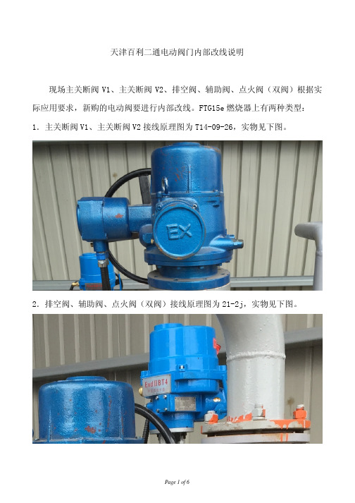
天津百利二通电动阀门内部改线说明现场主关断阀V1、主关断阀V2、排空阀、辅助阀、点火阀(双阀)根据实际应用要求,新购的电动阀要进行内部改线。
FTG15e燃烧器上有两种类型:1.主关断阀V1、主关断阀V2接线原理图为T14-09-26,实物见下图。
2.排空阀、辅助阀、点火阀(双阀)接线原理图为21-2j,实物见下图。
改接线准备:关闭UPS电源开关QF2,关闭主控制电源开关QF8。
改接线方案:1.主关断阀V1、V2接线原理图T14-09-26。
说明:打开电动阀接线端盖,取出接线端子盘,以下操作均在端子盘内侧(接了很多线那一边)进行。
拆下原接到端子盘上“E”端子的两根黄色线(电路图号及线号管均为N,见下图),分开两根线。
用手轮把电动阀转到约30度位置,分别测量两根线与“1”、“2”端子的通断情况。
和端子“1”(电路图号4)通的黄线接到端子“V”上,和端子“2”(电路图号8)通的黄线接到端子“U”上。
注意:原“U”端子、“V”端子上都有接线。
改完接线后,恢复端子盘位置,并且按燃烧器电气原理图中“控制箱外部接线图”完成接线。
下图为改线后电动阀接线图。
上盖,可以看到接线端子排如下。
拆下端子“3”(橙色)上面接的两根黄绿线,分开两根黄绿线。
用手轮把电动阀转到约30度位置,分别测量拆下的两根黄绿线与端子“4”、端子“5”的通断情况。
和端子“4”(电路图号5)通的黄线接到端子“2”上,和端子“5”(电路图号6)通的黄线接到端子“1”上。
注意:原“1”端子、“2”端子上都有接线。
改完接线后,按燃烧器电气原理图中“控制箱外部接线图”完成接线。
下图为改接线后原理图。
3.完成改接线后,首先要把电动阀手动转到45度(一半行程),然后合上控制电源QF8并监控电动阀开闭情况,控制系统正常启动后(蜂鸣器开始报警),会自动关闭各个电动阀,如果改接线后电动阀不动作或动作方向不对,应立即断开QF8并检查接线问题。
Parker Hannifin Veriflo 735W系列双阶段联动膜式调压阀说明说明书
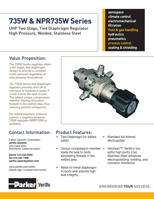
VerifloContact Information:Parker Hannifin Corporation Veriflo Division 250 Canal BlvdRichmond, California 94804phone 510 235 9590fax 510 232 7396************************/verifloMobile App: /verifloValue Proposition:The 735W Series regulator offers a two stage, tied diaphragm design to provide a constant outlet pressure regardless of inlet pressure fluctuations. The 735W Series tied diaphragm regulator provides shut off of corrosive or hazardous gases if a leak across the seat occurs. The added unique compression member loading eliminatesthreads in the wetted area, thus reducing particle entrapment. For subatmospheric pressure control, a negative pressure 735W regulator (NPR735W) is available.UHP Two Stage, Tied Diaphragm Regulator High Pressure, Welded, Stainless Steel735W & NPR735W SeriesProduct Features:• Tied Diaphragm for added safety• Unique compression member loads the seal to body eliminating threads in the wetted area • Metal-to-metal diaphragm-to-body seal assures high leak integrity• Standard full internal electropolish• Vericlean ™, Veriflo’s low sulfur high purity 316L Stainless Steel enhances electropolishing, welding, andcorrosion resistance735W & NPR735W SeriesFlow CurvesAdditional flow curves available upon requestDimensional Drawing100959085807570Flow (slpm)O u t l e t P r e s s u r e (p s i g )302520151050Flow (slpm)O u t l e t P r e s s u r e (p s i g )These tests were performed using Nitrogen at ambient conditions.Range 73530 = 1 - 30 psig 735100 = 3 - 100 psigNPR73530 = -25 in Hg - 0-30 psigBody MaterialW = 316L Stainless SteelPorting 2P = 2 Ports No X required for gauges,inlet & outlet ports only3P = 3 Ports One X for gauge port 4P = 4 Ports Two X’s for gauge ports See Regulator Porting Guide for additional options and port layoutsOutlet Gauge V3 = -30 in Hg 0 - 30 psigV1 = -30 in Hg 0 - 100 psig V2 = -30 in Hg 0 - 200 psig X =No GaugeAdditional ranges available upon requestInlet Gauge V1 = -30 in Hg 0 - 100 psig 10 = 0 - 1000 psig 30 = 0 - 3000 psig 40 = 0 - 4000 psig X =No GaugeAdditional ranges available upon requestPort StyleFS = 1/4” Face Seal TS = 1/4” Tube StubPort ConfigurationM = Male F = FemaleI = Internal Face Seal1/4” FS-M Gauge Ports are StandardOptional FeaturesThis section can have multiple optionsPM = Panel MountTH= Hastelloy Trim IncludesHastelloy C-22® diaphragm, compresson member, poppet and screen with an Inconel® spring VESP = Vespel ® Seat Recommendedfor N 2O Service123456781234567873530 W 4P V3 40 FS MMMM PM73530W4PV340FSMMMMPM735W & NPR735W SeriesOrdering InformationSample:Finished Order:Build a 735W or NPR735W Series regulator by replacing the numbered symbols with an option from the corresponding tables below.Color Explanations:For an explanation of Ordering optionsplease reference literature 25000275at /verifloBlack = Standard Lead Time Configurations Blue = Extended Lead Time ConfigurationsLitPN: 25000244 Rev: E Date of Issue 04/2013© 2009 Parker Hannifin CorporationVerifloOFFER OF SALE:The items described in this document are hereby offered for sale by Parker-Hannifin Corporation, its subsidiaries or its authorized distributors. This offer and its acceptance are governed by the provisions stated in the detailed “Offer of Sale” elsewhere in this document or available at /verifloWARNING USER RESPONSIBILITYFAILURE OR IMPROPER SELECTION OR IMPROPER USE OF THE PRODUCTS DESCRIBED HEREIN OR RELATED ITEMS CAN CAUSE DEATH, PERSONAL INJURY AND PROPERTY DAMAGE. THIS DOCUMENT IS FOR REFERENCE ONLY. PLEASE CONSULT FACTORY FOR LATEST PRODUCT DRAWINGS AND SPECIFICATIONSThis document and other information from Parker-Hannifin Corporation, its subsidiaries and authorized distributors provide product or system options for further investigation by users having technical expertise.The user, through its own analysis and testing, is solely responsible for making the final selection of the system and components and assuring that all performance, endurance, maintenance, safety and warning requirements of the application are met. The user must analyze all aspects of the application, follow applicable industry standards, and follow the information concerning the product in the current product catalog and in any other materials provided from Parker or its subsidiaries or authorized distributors.To the extent that Parker or its subsidiaries or authorized distributors provide component or system options based upon data or specifications provided by the user, the user is responsible for determining that such data and specifications are suitable and sufficient for all applications and reasonably foreseeable uses of the components or systems. The products described herein, including without limitation, product features, specifications, designs, availability and pricing are subject to change by Parker Hannifin Corp and it’s subsidiaries at any time without notice.Proposition 65 Warning: This product contains chemicals known to the state of California to cause cancer or birth defects or other reproductive harm.For additional information on materials of construction, functional performance and operating conditions, please see Regulator Technical Bulletin.Vespel® is a registered trademark of DuPont Performance Elastomers L.L.C.Hastelloy C-22® is a registered trademark of Haynes International, Inc.Inconel® is a registered trademark of Special Metals CorporationUse mobile device to scan this QR Code.Specifications735W & NPR735W Series。
西门子空调电动二通阀的接线
西门子空调电动二通阀的接线一、VVI46型二通阀 西门子46型二通阀,为常开型二通阀,在没有任何外力的情况下,阀门为打开状态。
阀门本身的设计又是流开型(流开型、流闭型阀如图一所示)。
图一 两种类型阀门流开型的常开阀门常规状态下阀杆上的复位弹簧不会受到水流的压力,相对于常闭型的阀门来说减少了对复位弹簧的要求。
可以看到西门子二通阀阀杆上的复位弹簧的弹性很小,无形中延长了阀门的使用寿命,减少了阀门的制作成本(不用将弹簧密封到阀体内部)。
使得西门子46型DN20二通阀在重量上比江森DN20二通阀减少0.2KG 左右。
而常开型阀门决定了执行器在制作上的相对复杂,控制方式也与常闭型阀门的执行器有所区别。
二、SUA21阀门执行器西门子VVF46型阀门属于常开型阀门,但是通常温控器的控制要求是当控制器输出正信号时阀门应该打开状态。
所以三线制阀门执行器,当执行器接通电源并且控制线上的控制信号为0V 时,阀门处于关闭状态;当电源接通且控制线上控制信号为220V 时,阀门处于流通状态。
SUA21的接线图如图二所示。
图二 SUA21接线图 西门子电动二通阀是西门子46型二通阀与SUA21电动执行器的组合。
46型二通阀为常开型阀门,执行器为电源和控制信号分开的控制方式(三线),不同于其他常闭型的阀门执行器(两线)。
这就造成很多用户不知道该怎样接线。
下面我将对西门子电动二通阀进行分解讲解。
流开型 流闭型Y---控制信号线,编号:BK 颜色:黑色 L---相线, 编号:BR 颜色:棕色 N---零线, 编号:BL 颜色:蓝色因为二通阀需要电源上带点的时候,才是关闭状态,所以为了达到更好的控制效果,建议当单个末端不使用时,关闭温控器开关,请勿关闭总电源。
三、电动二通阀与温控器配合西门子电动二通阀VVI46.20+SUA21通常与西门子温控器RDF310.2配合使用,其接线图如图三所示:图三RDF310.2与SUA21配合接线。
EBARA模拟量二通阀说明书(ARI)20121B2811
3、极限开关被顶动,可能调整的位置不正常。
1、参考说明书,检查接线正确性。
2、用表测量电源和控制信号
3、最好由专业调试人员重新调整极限开关。
电机转动而电动调节阀不动作
4、减速箱传动齿轮或轴套磨损。
5、极限开关位置与触动板距离大,不能切断电源。阀体已到极限位置,电机轴抖动不能停止。
B.调整阀位反馈与信号的对应:
反馈信号为0 V~10V时:
⑴将阀杆到底后,微调W3,使Y=(0.0~0.10)V;
⑵将阀杆到顶后,微调W4,使Y=(9.90~10)V;
⑶重复上述过程,检查Y值,如有超差,微调W3或W4使之为满足要求。
13.
常见故障
原因
解决办法
电动调节阀不动作
1、电源是否接入,与电动调节阀所需电源是否一致?
384
591
647
毛重(kg)
205
485
445
695
748
允许ΔP(kPa)
1000
执行机构类型
ARI PREMIO
全行程时间
<150s
密封力
12000N
最大功率损耗
115VA
6.
单位:mm
DN
200
250
300
350
350A
L
600
730
850
980
980
D
340
405
460
520
520
K
295
13、道内有异物,如焊碴等,阀芯阀座被卡住。
14、芯阀座被异物划伤变形。
15、介质压力较高,执行器推力不够。常出现用于调节蒸汽或高温高压介质。
海林自控动态流量平衡电动二通阀产品说明书

北京海林自控科技股份有限公司 第 1页 /共 1页 服务热线:4001010003
北京市昌平区回龙观国际信息产业基地发展路9号
网址:
动态流量平衡电动二通阀说明书
产品概述
本系列产品主要用于解决暖通空调系统中的水力失调问题,是集动态平衡和电动二通于一体的产品,特点是抗干扰能力强,控制精度高,在系统负荷波动较大的变流量系统中优势明显。
产品原理 ● 通过动态平衡功能动态平衡系统的阻力,保证设备输送介质流量在一定压差范围内不受系统压力波动影响,保持恒定。
●
根据设备的输入信号对电热式开关驱动器进行动作,实现阀的开关功能。
阀体技术参数
※流量按客户需求定制
驱动器技术参数:
安装尺寸
安装注意事项
1.注意驱动器参数,根据形式、工作电压等要求进行选择。
2.产品出厂前已经进行整机测试,应尽量避免现场拆卸及损坏驱动器。
3.预留空间以方便维护调试。
4.安装时应注意保证水流方向与阀体上箭头所指方向一致。
电动二通阀-VD32电动二通阀

电动二通阀-VD32电动二通阀调节阀>>电动调节阀>>电动二通阀产品名称:电动二通阀产品型号:VD32产品口径:DN25-50产品压力:0.6~10.0Mpa产品材质:铸钢、不锈钢、合金钢等产品概括:生产标准:国家标准GB、机械标准JB、化工标准HG、美标API、ANSI、德标DIN、日本JIS、JPI、英标BS生产。
阀体材质:铜、铸铁、铸钢、碳钢、WCB、WC6、WC9、20#、25#、锻钢、A105、F11、F22、不锈钢、304、304L、316、316L、铬钼钢、低温钢、钛合金钢等。
工作压力1.0Mpa-50.0Mpa。
工作温度:-196℃-650℃。
连接方式:内螺纹、外螺纹、法兰、焊接、对焊、承插焊、卡套、卡箍。
驱动方式:手动、气动、液动、电动。
产品详细信息电动二通阀概述:VD32驱动器系列执行器为直行程执行器,广泛应用于供热、通风、空调系统中;与二通VET 系列或者三通VST系列DN25—DN50调节阀门配套使用。
电动二通阀型号列表:电动二通阀型号尺寸电动二通阀特点:1、自动磁离合器控制装置,能在停顿的情况下产生稳定的扭力。
2、动用利用齿轮与螺杆传送,中心的齿轮采用绕中心的平面滚动轴承支撑,阀轴则采用中央螺套螺蚊连接。
3、高强度ABS阻燃工程塑料外壳,可防水及耐敲击。
4、可附辅助性手动控制杆,紧急情况下打开阀门。
5、附带阀门位置指示器,可适时清晰观察阀门开度。
电动二通阀工作原理:驱动器是由可逆同步马达驱动,并带磁性离合器。
马达通过马达转子与离合器所产生的磁性作用,能在停顿的情况下产生稳定的扭力。
故此当马达没有电流通过时,能稳定地停顿在任何一点,当阀门全开或全关时磁离合器分离,停止调节。
控制器的浮态式或比例式控制信号能使马达顺时转动或逆时转动。
电动二通阀技术参数:1、控制方式:浮态式控制2、马达种类型:带磁离合器的同步马达3、工作电压及功耗24VAC,50/60Hz 5.5VA4、驱动力800N/1500N5、驱动时间120S6、齿轮:不锈钢、黄铜、塑料7、支架:铸铝8、外壳:防火ABS工程塑料电动二通阀环境温度:工作:-5至+55℃储存:-20至65℃最大相对湿度92%不结露电动二通阀附件锁紧螺母、刻度标尺、刻度指示器控制信号: 0~10或4~20mA反馈信号: 0~10V电动二通阀接线原理其它阀系列价格供用户或设计院工程项目做预算管夹阀价格表口径手动电动DN50 450 1350 DN65 690 1575 DN80 1020 3375 DN100 1500 4050 DN125 1950 4500 DN150 **** **** DN200 4350 8400 DN250 7050 9750 DN300 12450 17700 DN350 21450 71700 DN400 29250 35400电动二通阀价格名称型号通径价格三速温控开液晶显示温控开关关大中小电动二通阀(风机管盘)VA70101.6mpa≤180℃DN15 87 37.5 78 75 72DN20 87 37.5 78 75 72DN25 127.5 37.5 78 75 72 HYDF1.6mpa≤120℃DN15 97.5 34.5 78 75 72DN20 97.5 34.5 78 75 72DN25 127.5 34.5 78 75 72名称通径价格电动二通阀配套驱动器,传感器,变压器,温度控制器DN25 600 DN32 630 DN40 675 DN50 720 DN65 1125 DN80 1575 DN100 1725 DN125 2100 DN150 23400 DN200 3450 DN250 5250 DN300 7800 DN350 9750 DN400 12900产品名称通径DN工作压力(mpa)1.6(Z)2.5(c)Y416XY110X 减压稳压阀25/110 225 270 32/110 285 345 40/110 315 382.5 50/110 345 42050 585 70565 630 75080 757.5 900 100 915 1095 125 1470 1770 150 1800 21750JM744X气80 825 990动,液动快开排泥阀100 900 1080 125 1575 1890 150 **** **** 200 1950 2340 250 3150 3780 300 4650 5580产品名称公称通径工作压(mpa)1.0/1.6CARX 复合式排气阀DN20DN25DN32DN40 507 DN50 507 DN65 591 DN80 637.5 DN100 675 DN125 862.5 DN150 1125 DN200 2250产品名称公称通径工作(mpa)1.0/1.6排气阀DN40 216 DN50 216 DN65 262.5 DN80 300 DN100 328.5 DN125 337.5 DN150 394.5 DN200 694.5 DN250 1125 DN300 1500 DN350底阀价格底阀H42F-6P口径4Ni 8Ni 普料DN15DN20DN25DN32DN40 172.5 217.5 135 DN50 240 277.5 150 DN65 315 382.5 210 DN80 457.5 517.5 277.5 DN100 525 570 307.5 DN125 720 900 540 DN150 **** ****.5 757.5 DN200 1650 2182.5 1140 DN250 2400 2775 1650 DN300 3450 3975 2625型号口径单位单价(元)双门底阀DN40 只255 DN50 只300 DN80 只495电动二通阀价格名称型号通径价格三速温控开关液晶显示温控开关大中小电动二通阀(风机管盘)VA70101.6mpa≤180℃DN15 87 37.5 78 75 72DN20 87 37.5 78 75 72DN25 127.5 37.5 78 75 72 HYDF1.6mpa≤120℃DN15 97.5 34.5 78 75 72DN20 97.5 34.5 78 75 72DN25 127.5 34.5 78 75 72名称通径价格电动二通阀配套驱动器,传感器,变压器,温度控制器DN25 600 DN32 630 DN40 675 DN50 720 DN65 1125 DN80 1575 DN100 1725 DN125 2100 DN150 23400 DN200 3450 DN250 5250 DN300 7800 DN350 9750 DN400 12900呼吸阀阻火器价格型号呼吸阀GFQ-2 阻火呼吸阀ZFQ-1 呼吸阀QZF-89 口径铸钢不锈钢铸钢不锈钢铸钢不锈钢DN25 187.5 450 255 502.5 //DN32 262.5 585 315 675 //DN40 277.5 660 330 705 //DN50 315 727.5 360 795 765 1905 DN65 397.5 922.5 465 1125 1005 2505 DN80 465 1170 555 1327.5 1080 2760 DN100 585 1417.5 705 1590 1215 3120 DN125 727.5 2100 915 2280 2085 4485 DN150 952.5 2415 1125 2670 2715 5880 DN200 1425 3367.5 1635 3795 3135 8625 DN250 1897.5 4560 2250 5355 4485 11115 DN300 3360 6555 3825 7905 5700 15015型号管道阴火器GYW-1 管道阻火器GZW-1 阻火器ZGB-1 口径铸钢不锈钢铸钢不锈钢铸钢不锈钢DN25 210 420 240 555 210 420 DN32 285 675 315 900 255 570DN40 315 765 345 1005 270 600 DN50 360 870 390 1170 315 690 DN65 420 1125 465 1635 345 840 DN80 555 1380 600 1815 450 1035 DN100 660 1635 720 2250 555 1305 DN125 810 2325 1005 3795 660 1980 DN150 **** **** 1350 4830 915 2325 DN200 1635 4320 1980 6645 1290 3150 DN250 2325 5865 2670 9495 1635 4395阻火透气帽公称通径铝合金铸钢不锈钢单价(元)单价(元)DN40 105 150 420 DN50 105 195 450 DN80 210 375 780 DN100 345 450 990 DN150 825 810 1635 DN200 1020 1065 2595型号公称通径铸钢不锈钢单价(元)单价(元)网型阻火器HGS一07DN25 382.5 570 DN40 630 1050 DN50 697.5 1125 DN65 900 1695 DN80 1035 1905 DN100 1417.5 2505 DN150 **** **** DN200 4050 7245 DN250 4275 10530 DN300 6007.5 13455管道砾石阻火器口径DN25 DN50 0N65 DN80 DN100 DN150 铸钢375 600 690 780 1080 1635流量计价格名称通径价格LDE智能型电磁流量计DN15 3300 DN20 3300 DN25 3300 DN32 3450 DN40 3450 DN50 3450 DN65 3450 DN80 3450 DN100 3600 DN125 3750 DN150 4050 DN200 4800 DN250 5700 DN300 7200 DN350 7800 DN400 9300 DN500 10800 DN600 13500 DN700 16500 DN800 21750 DN900 24750 DN1000 28500 DN1200 36000名称通径价格涡街流量计DN25 3450 DN32 3525 DN40 3600 DN50 3750 DN65 3900 DN80 4275 DN100 4500 DN125 5250 DN150 6300 DN200 8250 DN250 9750 DN300 11700水处理器价格多功能微电子水处理器DN20 1125 DN25 1125 DN32 1200 DN40 1200 DN50 1200 DN65 1275 DN80 1350 DN100 1500 DN125 1650 DN150 1875 DN200 2400 DN250 3000 DN300 3600 DN350 4200 DN400 5700 DN450 6750 DN500 8400 DN600 9000 DN700 12750 DN800 16500 DN900 21000 DN1000 24750名称通径价格内磁水处理器DN25 1500 DN32 1650 DN40 1725 DN50 1950DN6522502550 DN80 2550 DN100 3000 DN125 3750DN150 4350DN200 5700DN250 7350DN300 8700DN400 11250DN500 14250DN600 18000 橡胶接头价格KXT(JGD)可曲挠橡胶接头规格单球单球翻边单球翻边双球变径球l.OMPa 1.6MPa 2.5MPa l.OMPa 1.6MPa 1.OMPa规格型号1.OMPa DN25 61.5 61.5 118.5DN32 99 99 165 65×50 313.5 DN40 108 108 174 111 80×65 394.5 DN50 115.5 115.5 214.5 120 165 100×65 435 DN65 151.5 151.5 280.5 162 202.5 100×80 472.5 DN80 169.5 169.5 313.5 175.5 250.5100×125571.5 DN100 198 198 346.5 208.5 292.5100×150708 DN125 300 300 561 334.5 442.5125×150708 DN150 351 351 750 417 457.5 538.5200×1001170 DN200 487.5 544.5 1125 624 690 703.5 200x125 1170 DN250 646.5 792 1560 867 952.5 1056 200x150 1170 DN300 888 1015.5 2205 1224 1350 1287250×1251497 DN350 1023 1270.5 2352 1306.5 1440 2118250×1501497 DN400 1339.5 1639.5 3255 1809 1995 2178250×2001497 DN450 1617 2178 4200 22885.5 2565 0 300X200 1665 DN500 1815 2722.5 5460 3033 3337.5 4290300×2501665 DN600 2392.5 8070 4483.5 4935 6154.5 350X200 1873.5KXT(JGD) 可曲挠橡胶接头 规格 单球单球翻边 单球翻边双球变径球l.OMPa 1.6MPa 2.5MPa l.OMPa 1.6MPa 1.OMPa规格型号1.OMPa DN700 3157.5 9892.5 5494.5 6045 7590 350*300 1873.5 DN800 429012022.5 6679.5 7350 8745 400*300 2068.5 DN900 5313 7986 8790 0 400*350 2236.5DN1000 61359438 10380 12243 1200*8032670DN1100 82500 备注以上产品橡胶为天然胶, 法兰锻钢。
英霏尼兰电动阀答疑
Enfinilan电动阀答疑
电动二通阀
a.黄铜阀体在放置一定时间后颜色变暗是质量问题吗?
答疑:不是质量问题,黄铜接触空气会产生氧化作用,颜色逐渐变暗。
黄铜耐腐蚀性较强,是阀门常用的材质。
b.怎么从图纸上确定电动二通阀的设计数量?
答疑:一般情况下,一个风机盘管就需要配套一个电动二通阀,因此根据风机盘管的数量即可核算出电动二通阀的需求数量。
c.执行器的两根线哪个是正极,哪个是负极?
答疑:执行器的两根接线不分正负极。
d.电动二通阀安装后出现漏水问题,是不是产品质量出了问题?
答疑:电动二通阀出现外泄漏,有很多可能的原因,可能是产品质量问题引起的外泄漏,也不排除其他外因所致。
例如,工人安装时用力过猛将连接螺纹弄断导致连接处松动,此时也会导致漏水。
阀门在出厂时都会经过外观检验和打压试验,出现阀体裂纹、打压漏气的不被允许出厂。
电动调节阀
e.电动执行器中的BOOEY代表什么意思?
B代表AC24V电源,OO为负极,E为输入信号,Y为反馈信号,只需要接4个线即可。
f.阀体和执行器匹配主要依据是什么?
答疑:一个看行程是否匹配,二是看扭矩是否匹配。
g.调节阀可当做开关阀使用吗?
如果执行器更换成开关型的,调节阀也可以只开和关,这时执行器中没有定位器。
f.怎么从图纸上确定电动调节阀的设计数量?
答疑:一个新风机组对应一个电动调节阀,一个空气处理机组对应一个电动调节阀。
英塞尔斯·兰德双膜空气驱动泵操作手册说明书

OPERATOR’S MANUAL PX01X-XXX-XXX-AXXXINCLUDING: OPERATION, INSTALLATION & MAINTENANCERELEASED: 3-7-13REVISED: 5-13-16(REV: H)1/4" DIAPHRAGM PUMPINGERSOLL RAND COMPANY LTD209 NORTH MAIN STREET – BRYAN, OHIO 43506✆ (800) 495-0276 • FAX (800) 892-6276 © 2016CCN 80448053PUMP DATAModels . . . . . . see Model Description Chart on page 2 for “-XXX” optionsPump Type . . Non-Metallic Air Operated Double Diaphragm Material . . . . . see Model Description ChartWeight . . . . . . Polypropylene . . . . . . . . 2 .86 lbs (1 .30 kgs) PVDF . . . . . . . . . . . . . . . . . 3 .88 lbs (1 .76 kgs) Acetal . . . . . . . . . . . . . . . . 3 .52 lbs (1 .60 kgs)Maximum Air Inlet Pressure . . . . . . . . 125 psig (8 .6 bar)Minimum Air Inlet Pressure . . . . . . . . . 10 psig (0 .69 bar)Maximum Outlet Pressure . . . . . . . . . . 125 psig (8 .6 bar)Maximum Flow Rate . . . . . . . . . . . . . . . . 5 .3 gpm (20 lpm)Maximum Material Inlet Pressure . . . . 10 psig (0 .69 bar)Displacement / Cycle @ 125 psig . . . . 0 .019 gal / 0 .072 ltrs Maximum Particle Size . . . . . . . . . . . . . 1/16” dia . (1 .6 mm)Maximum Temperature Limits (diaphragm / ball / seat material)Acetal . . . . . . . . . . . . . . . . . . . . 10° to 180° F (-12° to 82° C)E .P .R . / EPDM . . . . . . . . . . . . . . -60° to 280° F (-51° to 138° C)Kynar® PVDF . . . . . . . . . . . . . . 10° to 200° F (-12° to 93° C)Hytrel® . . . . . . . . . . . . . . . . . . . -20° to 150° F (-29° to 66° C)Neoprene . . . . . . . . . . . . . . . . 0° to 200° F (-18° to 93° C)Nitrile® . . . . . . . . . . . . . . . . . . . 10° to 180° F (-12° to 82° C)Polypropylene . . . . . . . . . . . . 35° to 175° F (2° to 79° C)Viton® . . . . . . . . . . . . . . . . . . . . -40° to 350° F (-40° to 177° C)Santoprene® . . . . . . . . . . . . . . -40° to 225° F (-40° to 107° C)PTFE . . . . . . . . . . . . . . . . . . . . . . 40° to 225° F (4° to 107° C)Dimensional Data . . . . . . . . . . . . . . . . . . . see page 10Noise Level @ 70 psig, 60 cpm . . . . . . . . 62 .3 dB(A)①① The pump sound pressure levels published here have been updated to an Equivalent Continuous Sound Level (LA eq ) to meet the intent of ANSI S1 .13-2005, CAGI-PNEUROP S5 .1 .Mounting Adapter Plate Optional Accessory Kit (24123879) available . Please contact your nearest ARO / Ingersoll Rand customer service or distributor for details .Model PD01XModel PE01XFigure 1Page 2 of 12 PX01X-XXX-XXX-AXXX (en)MODEL DESCRIPTION CHARTModel Code ExplanationExample:PX01X-XXX-XXX-AXXXModel SeriesPD01-Standard Pump PE01-Electronic Interface Center Body Material P -Polypropylene E-Groundable Polypropylene ConnectionH-Hybrid 1/4” NPT / BSP Fluid Caps / Manifold Material D-Groundable AcetalE-Groundable Acetal (Multiple port)K-Kynar PVDFL-P-Kynar PVDF (Multiple port)PolypropyleneHardware Material S-Stainless SteelSeat / Spacer MaterialD-AcetalK-Kynar PVDF P-Polypropylene0-Polypropylene (Flex Check Spacer)1-Acetal (Flex Check Spacer)2-PVDF (Flex Check Spacer)Check MaterialA-Santropene C-Hytrel G-NitrileT-PTFE J-Nitrile ( ex check only)K-EPR ( ex check only)N-Neoprene ( ex check only)L-Viton ( ex check only)Diaphragm / O-Ring MaterialA-Santoprene C-Hytrel G-Nitrile T-PTFE RevisionA-RevisionSpecialty Code 1 (Blank if no Speciality Code)B-Solenoid 12VDC, 24VAC and 22VAC D-Solenoid 24VDC, 48VAC and 44VAC A-Solenoid 120VAC,110VAC AND 60VDC C-Solenoid 240VAC, 220VAC AND 120VDC G-Solenoid 12VDC ATEX / IECex H-Solenoid 24VDC ATEX / IECex K-Solenoid 220VAC ATEX / IECex N-Solenoid with no Coil0-Standard Valve Block (No Solenoid)Specialty Code 2 (Blank if no Speciality Code)NOTICE: All possible options are shown in the chart, however, certain combinations may not be recommended. Consult a representative or the factory if you have questions concerning availability.G-End of Stroke ATEX / IECex / NEC / CECF-End of Stroke feedback / cycle sensing ( with M12 Circular Connector)R-End of Stroke NECE-End of Stroke feedback / cycle sensing (with M12 Circular Connector) + Leak Detection T-End of Stroke NEC / Leak Detection NEC 0-No optionSpecial TestingFor Special Testing options, please contact your nearest Ingersoll Rand Customer Service Representative or Distributor.R-Polypropylene (Multiple port) H-End of Stroke + Leak Detection ATEX / IECex / NEC / CEC L-Leak DetectionM-Leak Detection ATEX / IECex / NEC / CEC E-Solenoid 12VDC NEC / CEC F-Solenoid 24VDC NEC / CEC J-Solenoid 120VAC NEC / CECEXCESSIVE AIR PRESSURESTATIC SPARKWARNING EXCESSIVE AIR PRESSURE. Can cause per- sonal injury, pump damage or property damage.y Do not exceed the maximum inlet air pressure as stated on the pump model plate.y Be sure material hoses and other components are able to withstand fluid pressures developed by this pump. Check all hoses for damage or wear. Be certain dispens-ing device is clean and in proper working condition. WARNING STATIC SPARK. Can cause explosion resulting in severe injury or death. Ground pump and pumping system.y PX01X-HDS-XXX are Groundable Acetal pumps: Use the pump ground lug provided. Connect to a 12 ga. (minimum) wire (kit 66885-1 is included) to a good earth ground source.y Sparks can ignite flammable material and vapors.y The pumping system and object being sprayed must be grounded when it is pumping, flushing, recirculating or spraying flammable materials such as paints, solvents, lacquers, etc. or used in a location where surrounding atmosphere is conducive to spontaneous combustion. Ground the dispensing valve or device, containers, hos-es and any object to which material is being pumped. y Secure pump, connections and all contact points to avoid vibration and generation of contact or static spark.y Consult local building codes and electrical codes for specific grounding requirements.y After grounding, periodically verify continuity of electrical path to ground. Test with an ohmmeter from each component (e.g., hoses, pump, clamps, con-tainer, spray gun, etc.) to ground to insure continuity. Ohmmeter should show 0.1 ohms or less.y Submerse the outlet hose end, dispensing valve or device in the material being dispensed if possible. (Avoid free streaming of material being dispensed.) y Use hoses incorporating a static wire.y Use proper ventilation.y Keep inflammables away from heat, open flames and sparks. y Keep containers closed when not in use. WARNING Pump exhaust may contain contaminants. Can cause severe injury. Pipe exhaust away from work area and personnel.y In the event of a diaphragm rupture, material can be forced out of the air exhaust muffler.y Pipe the exhaust to a safe remote location when pumping hazardous or inflammable materials.y Use a grounded 1/4” minimum i.d. hose between the pump and the muffler.WARNING HAZARDOUS PRESSURE. Can result in serious injury or property damage. Do not serviceor clean pump, hoses or dispensing valve while the system is pressurized.y Disconnect air supply line and relieve pressure from the system by opening dispensing valve or device and / or carefully and slowly loosening and removing outlet hose or piping from pump.WARNING HAZARDOUS MATERIALS. Can cause serious injury or property damage. Do not attempt to returna pump to the factory or service center that contains hazardous material. Safe handling practices must comply with local and national laws and safety code requirements.y Obtain Material Safety Data Sheets on all materials from the supplier for proper handling instructions.CAUTIONpump wetted parts and the substance being pumped, flushed or recirculated. Chemical compatibility may change with temperature and concentration of the chemical(s) within the substances being pumped, flushed or circulated. For specific fluid compatibility, consult the chemical manufacturer.CAUTIONon mechanical stress only. Certain chemicals will significantly reduce maximum safe operating temperature. Consult the chemical manufacturer for chemical compatibility and temperature limits. Refer to PUMP DATA on page 1 of this manual.CAUTIONhave been trained for safe working practices, understand it’s limitations, and wear safety goggles / equipment when required.CAUTIONsupport of the piping system. Be certain the system components are properly supported to prevent stress on the pump parts.y Suction and discharge connections should be flexible connections (such as hose), not rigid piped, and should be compatible with the substance being pumped.CAUTIONpump. Do not allow pump to operate when out of material for long periods of time.y Disconnect air line from pump when system sits idle for long periods of time.CAUTION Use only genuine ARO ® replacement parts to assure compatible pressure rating and longest service life. NOTICENOTICE RE-TORQUE ALL FASTENERS BEFORE cause fasteners to loosen. Re-torque all fasteners to insureRupture” pn \ 93122WARNINGCAUTIONOPERATING AND SAFETY PRECAUTIONSREAD, UNDERSTAND, AND FOLLOW THIS INFORMATION TO AVOID INJURY AND PROPERTY DAMAGEPX01X-XXX-XXX-AXXX (en) Page 3 of 12Page 4 of 12 PX01X-XXX-XXX-AXXX (en)y Kynar® is a registered trademark of the Arkema Inc . y Loctite® and 242 are registered trademarks of the Henkel Loctite Corporation yy ARO® is a registered trademark of Ingersoll-Rand Company y Santoprene® is a registered trademark of Monsanto Company, licensed to Advanced Elastomer Systems, L .P . yy Lubriplate® is a registered trademark of Lubriplate Division (Fiske Brothers Refining Company) yGENERAL DESCRIPTIONThe ARO diaphragm pump offers high volume delivery even at low air pressures, easy self priming and the ability to pump various viscosity materials . The pump is designed to corre-spond to the needs of the user by offering a variety of wetted parts configurations to handle almost any application .Air operated double diaphragm pumps utilize a pressure differential in the air chambers to alternately create suction and positive fluid pressure in the fluid chambers . Flat checks insure a positive flow of fluid .Pump cycling will begin as air pressure is applied and it will continue to pump and keep up with the demand . It will build and maintain line pressure and will stop cycling once maxi-mum line pressure is reached (dispensing device closed) and will resume pumping as needed .The Acetal material used in this pump contains stainless steel fibers . It’s conductivity allows it to be connected to a suitable ground . A ground screw is provided for this .AIR AND LUBE REQUIREMENTSWARNING y A filter capable of filtering out particles larger than 50 microns should be used on the air supply . In most ap-plications there is no lubrication required other than the “O” ring lubricant which is applied during assembly or repair . y The pump, when fitted with flex checks, can be rotated 360° to suit the application . It may be mounted upside down or on the wall with no effect on suction lift or op-erating efficiency . The filter and regulator need to be ori-ented in a normal vertical direction to function properly . y If lubricated air is present, make sure that it is compatible with the “O” rings and seals in the air motor section of the pump .INSTALLATIONy Apply PTFE tape or pipe sealant to threads upon assem-bly to prevent leakage .y Secure the diaphragm pump legs to a suitable surface to insure against damage by vibration .y When the diaphragm pump is used in a forced-feed (flooded inlet) situation, it is recommended that a “Check Valve” be installed at the air inlet .OPERATING INSTRUCTIONSy Always flush the pump with a solvent compatible withthe material being pumped if the material being pumped is subject to “setting up” when not in use for a period of time .y Disconnect the air supply from the pump if it is to be in-active for a few hours .y The outlet material volume is governed not only by the air supply, but also by the material supply available at the inlet . The material supply tubing should not be too small or restrictive . Be sure not to use hose which might col-lapse .MAINTENANCEy This product is not intended to be repairable . However, some service items are available .y Provide a clean work surface to protect sensitive internal moving parts from contamination from dirt and foreign matter during service disassembly and reassembly .y Keep good records of service activity and include the pump in preventive maintenance program .y At the end of its service life, please dispose of pump and contents properly .PE01X PUMP OPERATIONy Solenoid control allows the cycle rate of the pump to becontrolled electronically .With Solenoid control, when the solenoid is energized, the pump strokes and dispenses the fluid in one cham-ber . When the solenoid is de-energized, the pump strokes in the opposite direction, dispensing the fluid in the other chamber .By providing continuous ON - OFF signals to the solenoid, the fluid transfer rate may be increased or decreased re-motely .y End of stroke feedback can be used in conjunction with the solenoid valve to cycle the pump based upon com-pletion of each stroke .y The leak detection option incorporates an optical fluid sensor in each air chamber to provide a signal when a diaphragm has failed and fluid is leaking through the pump .PX01X-XXX-XXX-AXXX (en)Page 5 of 12Note: Item (19) O-ring is not used with Flex Check Options.MATERIAL CODE[B] = Nitrile [Co] = Copper [D] = Acetal[E] = E .P .R . / EPDM [G] = Nitrile[GP] = Groundable Polypropylene [H] = Hytrel[K] = Kynar PVDF [N] = Neoprene [P] = Polypropylene [Sp] = Santoprene [SS] = Stainless Steel [T] = PTFE[U] = Polyurethane [V] = VitonPage 6 of 12 PX01X-XXX-XXX-AXXX (en)6112219266010164 (P T F E m o d e l s o n l y )26212167772643656415726(f o r e x c h e c k m o d e l s , 4 p l a c e s )42☞ TORQUE REQUIREMENTS ☜NOTE: DO NOT OVERTIGHTEN FASTENERS.① (26) Screws 51-55 in. lbs (5.8 - 6.2 Nm).② (6) Diaphragm Screw / Washer 60-70 in. lbs (6.8 - 7.9 Nm).LUBRICATION / SEALANTS③ Apply Lubriplate FML-2 grease (94276) to all “O” rings, “U” cups and mating parts.④ Apply Loctite® 242® to threads.PX01X-XXX-XXX-AXXX (en) Page 7 of 12Page 8 of 12 PX01X-XXX-XXX-AXXX (en)PD01X-XXX-XXX-AXXX - Air Section1012612917313213510726 137 111 33311167PE01X-XXX-XXX-AXXX - Air Section42111111071374204192610126 12928313513231334144174034164154184134291673173☞ TORQUE REQUIREMENTS ☜NOTE: DO NOT OVERTIGHTEN FASTENERS.① (26) Screws 25-28 in.lbs (2.8 - 3.2 Nm)LUBRICATION / SEALANTS③ Apply Lubriplate FML-2 grease (94276) to all “O” rings, “U” cups and mating parts.④ Apply Loctite® 242® to threads.PX01X-XXX-XXX-AXXX (en) Page 9 of 12Solenoid Wiring DiagramEnd of Stroke / Cycle Sensor Pinout, M12 ConnectorEnd of Stroke / Cycle Sensor Pinout Wiring Diagram (No Connector)1 BROWN PNP Output L L -+10 TO +30 VDC 0VDCLoad 200 mA MAX 4 BLACK3 BLUEDiaphragm Failure Detector Wiring DiagramTURCK (PICOFAST) CONNECTOR PSW 3M -2/90143BNPIN 1SCHEMATICSENSOR SCHEMATICBLK PIN 4LOAD 40 mA MAX-+BU PIN 324.0 + 10%VDCPINOUT FUNCTION 1 (BN)+ 24 VDC 3 (BU)0 VDC 4 (BLK)SIGNALPage 10 of 12 PX01X-XXX-XXX-AXXX (en)Pumps that will operate in environments defined as “hazardous locations” must only be installed, connected and set-up by qualified personnel with knowledge and understanding of protection classes, regulations and provisions for apparatus in haz-ardous areas, for the region where the pump will operate, because these regulations and provisions, along with the definition of what constitutes hazardous areas vary by location .Make sure the pump and its accessories comply with the specific requirements of the area it will be installed in . ARO Electronic interface Pumps (PE series) and its components are available with the following certifications:y United Statesy Class I, Division 1, Groups A-D, T4 y Class II, Division 1, Groups E-G, T135°C y Class I, Zone 1, Group IIC, T4 y Zone 20, Group IIIC, T135°C y Canaday Class I, Division 1, Groups A-D, T4 y Class II, Division 1, Groups E-G, T135°C y Class I, Zone 1, Group IIC, T4 y Zone 20, Group IIIC, T135°C y ATEX (Europe)y ATEX Category 2 y Zone 1, Group IIC, T4y Zone 21, Group IIIC, T135°C y IECy IEC Category 2y Zone 1, Group IIC, T4y Zone 21, Group IIIC, T135°CINSTALLATION OF ELECTRONIC INTERFACE COMPONENTS FOR HAZARDOUS DUTYAPPLICATIONSPX01X-XXX-XXX-AXXX (en) Page 11 of 12DIMENSIONAL DATADimensions shown are for reference only, they are displayed in inches and millimeters (mm) .DIMENSIONSA - 7 .2” (182 mm)H- 1 .9” (48 .6 mm)Q - 1/4 - 18 PTF SAE Short Z - 1/4 - 18 PTF SAE ShortB - 3 .9” (100 .0 mm)J - 2 .4” (61 mm)R- 3/4-14 NPTFC - 4 .6” (117 .0 mm)K - 3 .9” (99 mm)S - 1/4 NPTF / BSPT HybridD- 6 .8” (173 .0 mm)L - 2 .1” (53 mm)T - 1/4 NPTF / BSPT HybridE- 0 .3” (8 .8 mm)M - 3 .2” (81 mm)U- 3/4-14 NPTFF- 6 .1 ” (156 mm)N - 7 .2” (184 mm)X - 1/4-18 NPTF / BSPT HybridG- 0 .8” (20 .7 mm)P - 6 .0” (153 mm)Y - 1/4 NPTF / BSPT HybridMultiport Options Discharge Manifold has (2) and Inlet Manifold has (3) .。
Parker Hannifin 电子流量控制阀门DF083系列说明书

SpecificationsRated Flow Maximum Inlet PressureMaximum Internal Leakage Hysteresis Cracking (Deadband)Frequency Operating Temp.Range (Ambient)Cartridge Material Body Material Filtration Mounting (2)(3)Performance CurvesSolenoid Coil SpecificationsResponse Time Within Regulating Zone 50ms Wire Class “H ” for all voltagesVoltage 10VDC 12VDC 18VDC 24VDC 36VDC 48VDC Duty HD.HD.HD.HD.HD.HD.Watts (Nominal)303030303030Amps3.202.301.861.200.880.58Hydraulic Oil 135 SSU @ 100°F (28 cSt)F l o wInput Current12 VDC,30W Coil,200 Hz1.5.5 1.0A2.02.5Flow GainFlow (Q)7.623.81LPM GPM11.4315.14Hydraulic Oil 135 SSU @ 100°F (28 cSt)8.65.26.91.73.5P r e s s u r e D r o p (P )∆Pressure Drop vs.FlowSeries DF083DimensionsSeries DF083Ordering Information3Type08SizeDFProportional Flow Control Valve3/4-16UNF-2B Threaded CavitySealsCode Type Omit Nitrile VFluorocarbonOverride Option******calls out voltage. For example: 851024-012VDC is a 12 volt, 30 watt DC Double Wire coil.Coil Assemblies851018******30 Watt Conduit Coil 851020******30 Watt DIN(Hirschmann) Coil851022******30 Watt Double Spade CoilSERVICE PARTSNitrile Seal Kit: SK08-3Coil Nut: 118113-00Fluorocarbon Seal Kit: SK08-3V DIN Connector:Grey - 692914Black - 692915851024******30 Watt Double Wire Coil 851026******30 Watt Single Screw Coil 851028******30 Watt Single Wire CoilShipping Weight Cartridge Only .31 kg (.69 lbs.)Cartridge in Body .64 kg (1.4 lbs.)N3Flow OptionBody OptionCoil VoltageCoil WattageCoil TerminationMCode Wattage Omit Cartridge without Coil H30 WattTwo Position Three WayCode Port Size & MaterialOmit Cartridge Only 4P1/4″ NPTF (B08-3-4P)SteelA4P 1/4″ NPTF (B08-3-A4P)Aluminum 6P 3/8″ NPTF (B08-3-6P)SteelA6P 3/8″ NPTF (B08-3-A6P)Aluminum 4TSAE-4(B08-3-4T)SteelA4T SAE-4(B08-3-A4T)Aluminum 6T SAE-6(B08-3-6T)SteelA6T SAE-6(B08-3-A6T)Aluminum4B1/4″ BSPG (B08-3-4B)SteelA4B 1/4″ BSPG (B08-3-A4B)Aluminum 6B 3/8″ BSPG (B08-3-6B)SteelA6B3/8″ BSPG (B08-3-A6B)AluminumCode DescriptionOmit Cartridge Without Coil C1/2″ NPTF Conduit Connector with 24″ Class H Wire D DIN 43650(Hirschmann) Plug Face PSAE 1B-0.25 SAE Double Spade (DC Only)S1Single 8-32 screw & nut internally ground (DC Only)WDouble wire 24″ Class H (DC Only)W1Single wire, internally ground, 24″ Class H (DC Only)Code TypeOmit Cartridge Without Coil D01010 VDC D01212 VDC D01818 VDC D02424 VDC D03636 VDC D04848 VDCCode Type MPush TypeManual Override with Flush RodCode Description N311 LPM (3 GPM)@ 70 ∆P。
7MF1567选型
(PED 97/23/EC) Lloyds Register of Shipping (LR) Germanischer Lloyds Register of Shipping (GL) American Bureau of Shipping (ABS) Bureau Veritas (BV) Det Norske Veritas (DNV) Drinking water approval (ACS) GOST
25 bar 40 bar 60 bar 60 bar 96 bar 150 bar 240 bar 360 bar 600 bar 960 bar 1500 bar 2400 bar 2500 bar
3BD 3BE 3BG 3CA 3CB 3 CD 3CE 3 CG 3 DA 3DB 3 DD 3DE 3 DG 9AA 0 10 0 1 H1 Y
,
mm
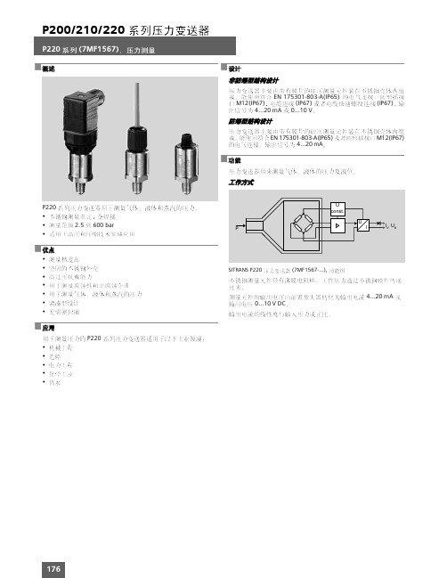
SITRANS P220,
,
mm
180
EN 175301
EN 175301
M12x1
M12x1
EN 175301 (Ex)
M12x1 (Ex)
181
Pg
4 ... 20 mA (UB - 10 V) / 0.02 A UB DC 7 ... 33 V (10 ... 30 V 0 ... 10 V DC 10 k UB 12 ... 33 V DC < 7 mA
0.25 % 0.5 % T99 < 5 ms 0.25 % 0.25 %/10 K 0.005 %/V -30 ... +120 °C -25 ... +85 °C -50 ... +100 °C ( EN 60529) IP 65 803-A IP 67 IP 67 IP 67 M12 EN 175301/
- 1、下载文档前请自行甄别文档内容的完整性,平台不提供额外的编辑、内容补充、找答案等附加服务。
- 2、"仅部分预览"的文档,不可在线预览部分如存在完整性等问题,可反馈申请退款(可完整预览的文档不适用该条件!)。
- 3、如文档侵犯您的权益,请联系客服反馈,我们会尽快为您处理(人工客服工作时间:9:00-18:30)。
4.产品选型
型号
通径
FZCV-0015 1/2〞(15mm)
形式 常闭二通
Kv(Cv)值 2.2(2.5)
允许压差 (MPa)
0.22
FZCV-0315 1/2〞(15mm) 分流三通 2.6(3.0) 0.22
FZCV-0020 3/4〞(20mm) 常闭二通 3.0(3.5) 0.20
FZCV-0320 3/4〞(20mm) 分流三通 3.4(4.0) 0.20
B 端主管道
电源 温控开关
A 端旁通管道
图3
风
机
盘 管
供水管
回水管
如果需要手动开启电动阀时,应轻轻地缓慢向外推动手动操作杆,当 操作杆处于卡口上方时,轻向下按,使操作杆落入卡口内,此时阀呈 现全通状态。向上拨动操作杆,阀门在弹簧作用下可以自动复位,电 动阀又处于一般工作状态。
Page 1 of 1
FZCV-0025 1〞(25mm) 常闭二通 6.9(8.0) 0.18
FZCV-0325 1〞(25mm) 分流三通 6.5(7.5) 0.18
Enfinilan 中国 | 楼宇自控•暖通空调•水力平衡 .50216.V01
型号
A
FZCV-0015
72
FZCV-0315
72
FZCV-0020
FZCV 系列常闭型电动二通阀
使用说明书
5.外形尺寸
Enfinilan
图 1 二通阀
安装、使用产品之前,请仔细阅读使用说明书。 安装、调试、运行及维护必须由具有相关资质的专业人
员进行。 请妥善保管使用说明书以备后用。
图 2 三通阀
1.功能描述
FZCV系列常闭型电动二通阀用于空 调末端水路控制,分为二通阀、三 通阀。其由温控器(又称恒温器) 控制电动阀电机,并通过减速机构 和复位弹簧使阀门开或关,从而实 现管道里的介质流通或断开,再通 过风机盘管送风,实现温度的自动 控制。
2.产品特点
阀门不工作时处于常闭状态; 锻压黄铜阀体; 不锈钢基座、铝外壳; 采用全封闭单向磁滞同步电机驱动,不锈钢弹簧复位; 电动阀为常闭二通型和分流三通型两类; 执行器和阀体卡扣连接,拆卸简单快速,安装使用方便。
3.技术参数
电源……………………………………AC220V±10% 50/60Hz 功率……………………………………6.5W 公称压力………………………………1.6Mpa 阀门动作时间…………………………开启时间≤13s 关闭时间≤7s 环境温度………………………………5~40℃ 介质温度………………………………2~90℃
80
FZCV-0320
80
FZCV-0025
80
FZCV-0325
80
B
C
23
88
36
88
23
96
37
96
ห้องสมุดไป่ตู้
23
98
42
98
6.安装操作说明
a.进水管与回水管的压差应控制在允许压差范围内。 b.电动阀应设置在容易安装、便于维修的地方。 c.电动阀的安装,通常应垂直安装,即电机在阀体上方,应避免潮湿。 d.安装二通阀时应注意,B 端为进水口,(A、B 标示在阀体的底部)。 e.安装三通阀时,介质的入口在阀的下端部(该端部不设标示)。 注意: 三通阀的 B 端在这里定为常闭端,A 端定为常通端。所以在安装管路 时 B 端接主管道,A 端接旁通管道。安装时请参照图 3。