(完整版)单点接地和多点接地剖析
详解电路设计中的单点接地-多点接地-混合接地
详解电路设计中的单点接地/多点接地/混合接地
地线也是有阻抗的,电流流过地线时,会产生电压,此为噪声电压,而噪声电压则是影响系统稳定的干扰源之一,不可取。
所以,要降低地线噪声的前提是降低地线的阻抗。
众所周知,地线是电流返回源的通路。
随着大规模集成电路和高频电路的广泛应用,低阻抗的地线设计在电路中显得尤为重要。
这里就简单列举几种常用的接地方法:
单点接地
单点接地,顾名思义,就是把电路中所有回路都接到一个单一的,相同的参考电位点上。
如下所以,在实际应用时,可以采用串联和并联混合的单点接地方式。
在画PCB 板时,把互相不易干扰的电路放一层,把互相容易发生干扰的电路放不同层,再把不同层的地并联接地。
如下多点接地
当电路工作频率较高时,想象一下高频信号在沿着地线传播时,所到之处影响周边电路会有多么严重,因此所有电路就要就近接到地上,地线要求最短,多点接地就产生了。
多点接地,其目的是为了降低地线的阻抗,在高频(f 一定的条件下)电路中,要降低阻抗,主要从两个方面去考虑,一是减小地线电阻,二是减小地线感抗。
1,减小地线导体电阻,从电阻与横截面的关系公式中我们知道,要增加地线导通的横截面积。
但是在高频环境中,存在一种高频电流的趋肤效应(也叫集肤效应),高频电流会在导体表面通过,所以单纯增大地线导体的横截面积往往作用不大。
可以考虑在导体表面镀银,因为银的导电性较其他导电物质优秀,故而会降低导体电阻。
试析低压配电接地方式分析及故障保护防范
试析低压配电接地方式分析及故障保护防范低压配电系统是工业和建筑领域中常见的电力配电系统之一,其接地方式的选择和故障保护对于系统的安全稳定运行至关重要。
在本文中,我们将就低压配电系统的接地方式进行分析,以及探讨故障保护的防范措施。
一、低压配电接地方式分析低压配电系统的接地方式主要有单点接地和多点接地两种方式。
1. 单点接地单点接地是指整个低压配电系统只有一个接地点,将所有的电气设备的金属外壳和接地回路都连接到这个接地点上。
单点接地具有接地电阻小、维护方便等优点,但缺点是一旦接地点出现了故障,整个系统都会受到影响。
在选择低压配电系统的接地方式时,需要根据具体的工程特点和要求来进行分析和选择。
一般来说,要求系统安全可靠、容错能力强的情况下,多点接地是更为合适的选择;而对于一些小型建筑或设备,单点接地则可以考虑。
二、故障保护防范在低压配电系统中,故障的发生是不可避免的,因此如何进行故障保护是至关重要的。
1. 过载保护在低压配电系统中,经常会出现过载现象,这会导致电缆和设备的过热甚至烧毁。
为了防止过载造成的损害,可以采取配电设备的额定容量选择、安装熔断器或断路器等方式进行保护。
2. 短路保护3. 接地故障保护接地故障是低压配电系统中的常见故障之一,如果不能及时处理,会对系统和设备造成严重危害。
为了防范接地故障,可以采取巡视、检测等措施来及时发现和处理接地故障,减少损失。
4. 漏电保护低压配电系统中的漏电故障会导致电气设备和人身安全受到威胁,因此需要采取漏电保护措施。
可以通过安装漏电断路器、残压保护器等设备来及时发现和隔离漏电故障。
以上所述仅为低压配电系统接地方式分析及故障保护防范中的一部分内容,根据不同的工程情况和需求,还需要对系统进行全面综合的分析和设计。
无论采用何种接地方式和防护措施,都需要保证系统的安全稳定运行。
希望本文所述内容能够对低压配电系统的设计和运行有所帮助。
小议单点接地及多点接地
小议单点接地及多点接地低频电路中,信号的工作频率小于1MHz,它的布线和器件间的电感影响较小,而接地电路形成的环流对干扰影响较大,因而应采用一点接地。
当信号工作频率大于10MHz时,地线阻抗变得很大,此时应尽量降低地线阻抗,应采用就近多点接地。
当工作频率在1~10MHz时,如果采用一点接地,其地线长度不应超过波长的1/20,否则应采用多点接地法。
数字地与模拟地之间单点接地,数字地之内多点接。
接地线干扰与设计地线设计是电磁兼容设计中大家都很注意,却又不知道应该怎样去做的一个问题。
了解了地线造成干扰问题的机理之后,在设计和实施地线时就有了一个明确的思路。
本期从介绍地线造成干扰的原理入手,使读者了解设计地线的关键和原则。
地线有安全地和信号地两种。
前者是为了保证人身安全、设备安全而设置的地线,后者是为了保证电路正确工作所设置的地线。
造成电路干扰现象的主要是信号地,因此这里仅讨论信号地的问题。
信号地的一般定义是:电路的电位参考点。
更恰当地说,这个定义是我们设计电路时的一个假设。
从这个定义是无法分析和理解一些地线干扰问题的。
从现在开始,我们在分析电磁兼容问题时,使用下面的定义。
地线是信号电流流回信号源的地阻抗路径。
既然地线是电流的一个路径,那么根据欧姆定律,地线上是有电压的;既然地线上有电压,说明地线不是一个等电位体。
这样,我们在设计电路时,关于地线电位一定的假设就不再成立,因此电路会出现各种错误。
这就是地线干扰的实质。
地线的阻抗一个难以理解的问题是,我们在设计地线时,都使地线的电阻很小,那么地线上的电位差怎么会大到导致电路出错的程度。
理解这个问题,要理解地线阻抗的组成。
地线的阻抗Z由电阻部分和感抗部分两部分组成,即:Z = RAC + jωL。
电阻成分:导体的电阻分为直流电阻RDC和交流电阻RAC。
对于交流电流,由于趋肤效应,电流集中在导体的表面,导致实际电流截面减小,电阻增加,直流电阻和交流电阻的关系如下:RAC= 0.076rf1/2RDC式中:r=导线的半径,单位cm,f=流过导线的电流频率,单位Hz, RDC= 导线的直流电阻,单位Ω。
试析低压配电接地方式分析及故障保护防范

试析低压配电接地方式分析及故障保护防范一、低压配电接地方式分析低压配电系统中,接地方式的选择对系统的安全可靠运行具有重要影响。
根据接地方式的不同,低压配电系统可以分为单点接地和多点接地两种方式。
1. 单点接地单点接地是指将低压配电系统中的中性点通过接地电阻接地,在正常运行状态下中性点与大地绝缘,只有在发生单相接地故障时,才会有电流通过接地回路。
单点接地方式适用于小型建筑或者对电源可靠性要求不高的场所,其优点是接地电流较小,不易造成接地电压升高,且可以减小故障范围,容易定位故障点。
但是单点接地也存在着一些缺点,比如当出现单相接地故障时,由于接地电阻较大,可能会造成接地电压升高,影响设备正常运行。
二、故障保护防范针对低压配电系统中可能存在的故障,在设计和运行中需要采取一系列的防范措施,以保障系统的安全可靠运行。
1. 常规保护装置在低压配电系统中,常规的保护装置主要包括过载保护、短路保护、接地故障保护等。
这些保护装置通过及时断开故障电路,保护设备和系统的安全运行。
其中过载保护主要是通过电流限制装置,当电路中的电流超过额定值时,及时切断电源,保护设备不受过大的电流损害;短路保护主要是通过断路器等装置,当电路中出现短路故障时,及时切断电源,防止电气设备和线路损坏;接地故障保护主要是通过接地故障保护装置,当出现接地故障时,及时切断故障回路,保护系统的安全运行。
2. 绝缘监测对于低压配电系统中的绝缘状态,需要进行定期的监测和检测。
通过使用绝缘监测装置,可以实时监测系统的绝缘状态,及时发现绝缘故障,进行处理和修复,以保障系统的安全运行。
3. 接地系统的维护和检测在低压配电系统中,接地系统对系统的安全运行起着关键的作用,需要定期对接地系统进行维护和检测。
包括对接地电阻的测量、接地系统的检查和维护、接地故障的处理等。
通过定期的接地系统检测和维护,可以保证系统的接地可靠性,降低接地故障对系统的影响。
4. 系统运行监控通过对低压配电系统的运行状态进行实时监控,及时发现系统运行中可能存在的故障和问题,采取相应的措施处理,以保障系统的安全可靠运行。
单点接地和多点接地剖析
单点接地和多点接地剖析在电气工程中,接地系统对于维持电力系统的安全和稳定至关重要。
在接地系统中,接地模式是关键因素之一。
常见的接地模式有单点接地和多点接地两种。
这篇文章将会从基本概念、应用范围、优缺点等方面对这两种接地模式进行剖析。
1. 单点接地1.1 概念与应用范围单点接地(Single Point Grounding,SPG)是指通过一个地点,将电气设备和系统接地。
该地点只连接电气系统的中性点和接地极,所有设备和系统的地线通过这个地点接地。
单点接地系统常见于低压电力系统、通讯设备等电气系统。
1.2 优点与缺点优点:•降低接地电阻,保证操作人员和设备安全。
•降低系统互感耦合,减小短路电流。
•减少干扰信号,提高系统抗干扰能力。
缺点:•不能应对电气系统接地设备故障,容易造成设备本体和操作人员受到电伤的危险。
•难以实现对设备的独立保护。
2. 多点接地2.1 概念与应用范围多点接地(Multiple Point Grounding,MPG)是指通过多个地点,将电气设备和系统接地。
每个地点只连接相应电气设备的地线,多个地点共同构成多点接地系统。
多点接地系统常见于高压电力系统,特别是中性点直接接地和低电阻接地系统。
2.2 优点与缺点优点:•利用多个接地点分散电气系统的散流电流,降低了环网电流的大小。
•对于接地设备故障的容错性更高,一个接地点故障不会影响整个电气系统的接地性能。
缺点:•多个接地点容易造成设备互相振荡,降低设备的稳定性。
•增加了系统的复杂度,需要加强设备的检修与维护。
3. 两种接地模式的比较单点接地和多点接地模式各有优缺点。
具体应用中,需要根据实际工程要求、设备技术水平、系统维护条件等多方面因素进行全面考虑。
下表列出了这两种接地模式的比较:接地模式优点缺点适用范围单点接地降低接地电阻、减小短路电流、提高抗干扰能力设备容易受到电伤、难以实现对设备的独立保护低压电力系统、通讯设备等多点接地降低环网电流、提高设备容错性设备易产生互相振荡、系统容易受到散热电势影响高压电力系统,特别是中性点直接接地和低电阻接地系统4.单点接地和多点接地是电气工程中常见的两种接地模式。
单点接地和多点接地
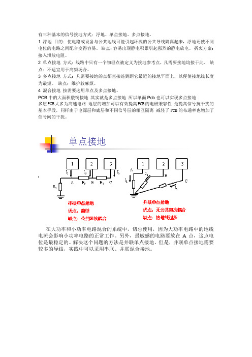
有三种基本的信号接地方式:浮地、单点接地、多点接地。
1 浮地目的:使电路或设备与公共地线可能引起环流的公共导线隔离起来,浮地还使不同电位的电路之间配合变得容易。
缺点:容易出现静电积累引起强烈的静电放电。
折衷方案:接入泄放电阻。
2 单点接地方式:线路中只有一个物理点被定义为接地参考点,凡需要接地均接于此。
缺点:不适宜用于高频场合。
3 多点接地方式:凡需要接地的点都直接连到距它最近的接地平面上,以便使接地线长度为最短。
缺点:维护较麻烦。
4 混合接地按需要选用单点及多点接地。
PCB中的大面积敷铜接地其实就是多点接地所以单面Pcb也可以实现多点接地多层PCB大多为高速电路地层的增加可以有效提高PCB的电磁兼容性是提高信号抗干扰的基本手段,同样由于电源层和底层和不同信号层的相互隔离减轻了PCB的布通率也增加了信号间的干扰。
在大功率和小功率电路混合的系统中,切忌使用,因为大功率电路中的地线电流会影响小功率电路的正常工作。
另外,最敏感的电路要放在A点,这点电位是最稳定的。
解决这个问题的方法是并联单点接地。
但是,并联单点接地需要较多的导线,实践中可以采用串联、并联混合接地。
将电路按照特性分组,相互之间不易发生干扰的电路放在同一组,相互之间容易发生干扰的电路放在不同的组。
每个组内采用串联单点接地,获得最简单的地线结构,不同组的接地采用并联单点接地,避免相互之间干扰。
这个方法的关键:绝不要使功率相差很大的电路或噪声电平相差很大的电路共用一段地线。
这些不同的地仅能在通过一点连接起来。
为了减小地线电感,在高频电路和数字电路中经常使用多点接地。
在多点接地系统中,每个电路就近接到低阻抗的地线面上,如机箱。
电路的接地线要尽量短,以减小电感。
在频率很高的系统中,通常接地线要控制在几毫米的范围内。
多点接地时容易产生公共阻抗耦合问题。
在低频的场合,通过单点接地可以解决这个问题。
但在高频时,只能通过减小地线阻抗(减小公共阻抗)来解决。
单点接地和多点接地的区别

工作频率低(<1MHz)的采用单点接地式(即把整个电路系统中的一个结构点看作接地参考点,所有对地连接都接到这一点上,并设置一个安全接地螺栓),以防两点接地产生共地阻抗的电路性耦合。多个电路的单点接地方式又分为串联和并联两种,由于串联接地产生共地阻抗的电路性耦合,所以低频电路最好采用并联的单点接地式。为防止工频和其它杂散电流在信号地线上产生干扰,信号地线应与功率地线和机壳地线相绝缘。且只在功率地线、机壳地线和接往大地的接地线的安全接地螺栓上相连(浮地式除外)。
2.多点接地
工作频率高(>30MHz)的采用多点接地式(即在该电路系统中,用一块接地平板代替电路中每部分各自的地回路)。因为接地引线的感抗与频率和长度成正比,工作频率高时将增加共地阻抗,从而将增大共地阻抗产生的电磁干扰,所以要求地线的长度尽量短。采用多点接地时,尽量找最接近的低阻值接地面接地。
单点接地和多点接地的区别
发布时间:2010-12-31 阅读次数:1517 次
接地为防止触电或保护设备的安全,把电力电讯等设备的金属底盘或外壳接上地线;利用大地作电流回路接地线。。在电力系统中,将设备和用电装置的中性点、外壳或支架与接地装置用导体作良好的电气连接叫做接地。接地的功用除了将一些无用的电流或是噪声干扰导入大地外,最大功用为保护使用者不被电击,以 UPS 而言,有些 UPS 会将零线与地线间的电压标示出来,确保产品不会造成对人体的电击伤害。
3.ቤተ መጻሕፍቲ ባይዱ合接地
工作频率介于1~30MHz的电路采用混合接地式。当接地线的长度小于工作信号波长的1/20时,采用单点接地式,否则采用多点接地式。
电路板接地基础知识讲解
电路板接地基础知识讲解电路板接地是电子设备中非常重要的一环,它不仅能确保电路的正常工作,还能提高电路的性能和抗干扰能力。
本文将对电路板接地的基础知识进行全面的讲解。
一、什么是电路板接地电路板接地,简单来说,就是将电子设备中的所有金属部件,如电路板、金属外壳等,通过导线连接到地面或大地,形成一个闭合的回路,以提供一个稳定的参考电位。
接地的主要作用有:保护电子设备和用户的人身安全、提供一个稳定的参考电位、降低电磁辐射和抗干扰能力等。
二、电路板接地的分类根据接地回路的不同,电路板接地可以分为以下几类:1. 单点接地:将所有金属部件连接到一个统一的接地点,形成一个单一的回路。
这种接地方式适用于一些简单的电子设备,但对于复杂的设备来说,由于存在大量的信号线和功耗线,单点接地会导致接地电流增大、接地电压上升等问题。
2. 多点接地:将电路板分为不同的区域,每个区域单独进行接地,形成多个接地回路。
这种接地方式可以减少接地回路之间的干扰,提高设备的抗干扰能力。
但同时也需要注意接地电位的一致性,避免产生不同区域之间的接地环路。
3. 信号与功耗分离接地:将信号线和功耗线分开接地,分别形成不同的接地回路。
这种接地方式可以有效地隔离信号线和功耗线之间的电磁干扰,提高电路的工作性能。
三、电路板接地的注意事项1. 确保接地导线足够粗大:为了降低接地回路的电阻,接地导线的选择应尽量粗大,以确保电流能够顺利地流回地面。
2. 避免接地回路产生环路:在设计电路板接地时,要注意避免接地回路之间产生环路,否则会引发信号串扰和电磁干扰等问题。
3. 注意接地点的位置选择:接地点的位置选择应尽量靠近电路板中心,并远离会产生干扰的元器件和线路,以提高接地的效果。
4. 接地回路与信号回路分离:在设计电路板时,要将接地回路与信号回路进行分离,避免相互干扰,同时也可以提高抗干扰能力。
四、电路板接地的测试方法为了确保电路板的接地效果良好,可以采用以下几种测试方法:1. 接地电阻测试:使用专业的测试仪器对接地回路的电阻进行测试,以确保接地回路的电阻在合理范围内。
信号接地的方式盘点(浮地-单点接地-多点接地)
信号接地的方式盘点(浮地/单点接地/多点接地)1.地的接法对于一个信号来说,它需要寻找一条最低阻抗的电流回流到地的途径,所以如何处理这个信号回流就变得非常的关键。
第一,根据公式可以知道,辐射强度是和回路面积成正比的,就是说回流需要走的路径越长,形成的环越大,它对外辐射的干扰也越大,所以,PCB布板的时候要尽可能减小电源回路和信号回路面积。
第二,对于一个高速信号来说,提供有好的信号回流可以保证它的信号质量,这是因为PCB上传输线的特性阻抗一般是以地层(或电源层)为参考来计算的,如果高速线附近有连续的地平面,这样这条线的阻抗就能保持连续,如果有段线附近没有了地参考,这样阻抗就会发生变化,不连续的阻抗从而会影响到信号的完整性。
所以,布线的时候要把高速线分配到靠近地平面的层,或者高速线旁边并行走一两条地线,起到屏蔽和就近提供回流的功能。
第三,为什么说布线的时候尽量不要跨电源分割,这也是因为信号跨越了不同电源层后,它的回流途径就会很长了,容易受到干扰。
当然,不是严格要求不能跨越电源分割,对于低速的信号是可以的,因为产生的干扰相比信号可以不予关心。
对于高速信号就要认真检查,尽量不要跨越,可以通过调整电源部分的走线。
许多电磁干扰问题是由地线产生的,因为地线电位是整个电路工作的基准电位,如果地线设计不当,地线电位就不稳,就会导致电路故障。
地线设计的目的是要保证地线电位尽量稳定,从而消除干扰现象。
信号接地方式一般有三种:浮地、单点接地、多点接地。
1.1 浮地目的:使电路或设备与公共地线可能引起环流的公共导线隔离起来,浮地还使不同电位的电路之间配合变得容易。
缺点:容易出现静电积累引起强烈的静电放电。
折衷方案:接入泄放电阻。
1.2 单点接地单点接地:所有电路的地线接到公共地线的同一点,进一步可分为串联单点接地和并联单点接地。
在大功率和小功率电路混合的系统中,切忌使用,因为大功率电路中的地线电流。
单点接地和多点接地剖析
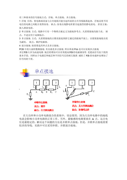
有三种基本的信号接地方式:浮地、单点接地、多点接地。
1 浮地目的:使电路或设备与公共地线可能引起环流的公共导线隔离起来,浮地还使不同电位的电路之间配合变得容易。
缺点:容易出现静电积累引起强烈的静电放电。
折衷方案:接入泄放电阻。
2 单点接地方式:线路中只有一个物理点被定义为接地参考点,凡需要接地均接于此。
缺点:不适宜用于高频场合。
3 多点接地方式:凡需要接地的点都直接连到距它最近的接地平面上,以便使接地线长度为最短。
缺点:维护较麻烦。
4 混合接地按需要选用单点及多点接地。
PCB中的大面积敷铜接地其实就是多点接地所以单面Pcb也可以实现多点接地多层PCB大多为高速电路地层的增加可以有效提高PCB的电磁兼容性是提高信号抗干扰的基本手段,同样由于电源层和底层和不同信号层的相互隔离减轻了PCB的布通率也增加了信号间的干扰。
在大功率和小功率电路混合的系统中,切忌使用,因为大功率电路中的地线电流会影响小功率电路的正常工作。
另外,最敏感的电路要放在A点,这点电位是最稳定的。
解决这个问题的方法是并联单点接地。
但是,并联单点接地需要较多的导线,实践中可以采用串联、并联混合接地。
将电路按照特性分组,相互之间不易发生干扰的电路放在同一组,相互之间容易发生干扰的电路放在不同的组。
每个组内采用串联单点接地,获得最简单的地线结构,不同组的接地采用并联单点接地,避免相互之间干扰。
这个方法的关键:绝不要使功率相差很大的电路或噪声电平相差很大的电路共用一段地线。
这些不同的地仅能在通过一点连接起来。
为了减小地线电感,在高频电路和数字电路中经常使用多点接地。
在多点接地系统中,每个电路就近接到低阻抗的地线面上,如机箱。
电路的接地线要尽量短,以减小电感。
在频率很高的系统中,通常接地线要控制在几毫米的范围内。
多点接地时容易产生公共阻抗耦合问题。
在低频的场合,通过单点接地可以解决这个问题。
但在高频时,只能通过减小地线阻抗(减小公共阻抗)来解决。
单点接地和多点接地
接地有多种方式,有单点接地,多点接地以及混合类型的接地。
而单点接地又分为串联单点接地和并联单点接地。
一般来说,单点接地用于简单电路,不同功能模块之间接地区分,以及低频(f<1MHz)电子线路。
当设计高频(f>10MHz)电路时就要采用多点接地了或者多层板(完整的地平面层)。
对于一个电子信号来说,它需要寻找一条最低阻抗的电流回流到地的途径,所以如何处理这个信号回流就变得非常的关键。
第一,根据公式可以知道,辐射强度是和回路面积成正比的,就是说回流需要走的路径越长,形成的环越大,它对外辐射的干扰也越大,所以,PCB布板的时候要尽可能减小电源回路和信号回路面积。
第二,对于一个高速信号来说,提供有好的信号回流可以保证它的信号质量,这是因为PCB 上传输线的特性阻抗一般是以地层(或电源层)为参考来计算的,如果高速线附近有连续的地平面,这样这条线的阻抗就能保持连续,如果有段线附近没有了地参考,这样阻抗就会发生变化,不连续的阻抗从而会影响到信号的完整性。
所以,布线的时候要把高速线分配到靠近地平面的层,或者高速线旁边并行走一两条地线,起到屏蔽和就近提供回流的功能。
第三,为什么说布线的时候尽量不要跨电源分割,这也是因为信号跨越了不同电源层后,它的回流途径就会很长了,容易受到干扰。
当然,不是严格要求不能跨越电源分割,对于低速的信号是可以的,因为产生的干扰相比信号可以不予关心。
对于高速信号就要认真检查,尽量不要跨越,可以通过调整电源部分的走线。
(这是针对多层板多个电源供应情况说的)模拟信号和数字信号都要回流到地,因为数字信号变化速度快,从而在数字地上引起的噪声就会很大,而模拟信号是需要一个干净的地参考工作的。
如果模拟地和数字地混在一起,噪声就会影响到模拟信号。
一般来说,模拟地和数字地要分开处理,然后通过细的走线连在一起,或者单点接在一起。
总的思想是尽量阻隔数字地上的噪声窜到模拟地上。
当然这也不是非常严格的要求模拟地和数字地必须分开,如果模拟部分附近的数字地还是很干净的话可以合在一起。
单点接地和 多点接地详解(Single point grounding and multipoint grounding)
单点接地和多点接地详解(Single point grounding andmultipoint grounding)Single point earthing multi point earthingThe problem to be solved in a single point is the "public ground impedance coupling" and the "low-frequency loop"",More often than not, it is aimed at "common mode interference" caused by long running linesIn low frequency circuits, the operating frequency of the signal is less than 1MHz, and its wiring and inductance between the devices are less affected, and the circulation caused by the grounding circuit has a greater impact on interference, so it should adopt one point grounding.When the signal operating frequency is greater than 10MHz, the ground impedance becomes very large. At this point, the ground impedance should be reduced as far as possible, and the ground multipoint grounding should be adopted.When the working frequency is between 1 and 10MHz, if one point grounding is adopted, the ground wire length shall not exceed 1/20 of the wavelength, or multipoint grounding method shall be adopted.Single point earthing between digital and analog ground, multipoint connection within digital ground.Ground wire interference and ground wire designGround design is a problem that people pay attention to in EMC design, but they don't know how to do it. After understanding the mechanism of the interference caused by ground wire, there is a definite idea in the design and implementation of ground wire. This issue begins with the introduction of the principle of interference caused by ground wire, enabling readers to understand the key and principles of designing ground wire. 1 what is the earth wire?There are two kinds of ground wire: safety and signal. The former is to ensure personal safety and equipment safety and set the ground wire, the latter is to ensure that the circuit works correctly set the ground wire. The main reason for the circuit interference is the signal ground, so the problem of signal ground is only discussed here.The general definition of the signal field is the potential reference point of the circuit.More appropriately, this definition is a hypothesis in our design of circuits. From this definition it is impossible to analyze and understand some ground interference problems. From now on, we will use the following definition when we analyze electromagnetic compatibility problems.The ground line is the ground impedance path of the signal current flowing back to the signal source.Since the ground wire is a path of the current, then there is a voltage on the ground line according to Ohm's law; since theearth is on a voltage, the earth line is not a equipotential body. In this way, when we design the circuit, the hypothesis about the potential of the ground wire is no longer established, so there are various errors in the circuit. This is the essence of ground interference.How big is the impedance of the 2 wire?An incomprehensible problem is that when we design the ground wire, the resistance of the ground wire is very small, then the potential difference on the ground will be large enough to cause the level of circuit errors. To understand the problem, understand the composition of ground impedance.The ground impedance of Z by the resistance and inductance part is composed of two parts, namely: Z = RAC + L J.Resistance component: the resistance of the conductor is divided into DC resistance RDC and AC resistance RAC. For AC current, because of the skin effect, the current is concentrated on the surface of the conductor, resulting in the decrease of the actual current cross section, the increase of resistance, and the relationship between the DC resistance and the AC resistance:RAC= 0.076rf1/2RDCType 1: the radius of the r= wire, the unit cm, the current frequency of the f= flowing through the wire, the unit Hz, the direct resistance of the RDC= wire, the unit omega.Inductance: any conductor has an internal inductance (which is distinguished from the usual external inductance,The outer inductance is a function of the area enclosed by the conductor, and the inductance is independent of the area enclosed by the conductor. For round sections, conductors are as follows:L=0.2S[ln (4.5/d) -1] (H)Type S= conductor length (m), d= conductor diameter (m)Table 1 illustrates the great difference between the DC and AC impedances. The impedance of very low frequencies can be considered to be the resistance of a conductor, can be seen from the table, with the increase of frequency, the impedance increases quickly when the frequency is above 100MHz, there are dozens of diameter 6.5mm ohm impedance of the wire length is only 10cm.Interference of 3 loop road and CountermeasuresLoop interference is a common interference that occurs between devices that are longer apart by longer cables. The intrinsic reason is the ground potential difference between the equipment. Ground voltage leads to the earth loop current. Due to the unbalanced circuit, the earth loop current leads to differential mode interference voltage that affects the circuit (Figure 1).The interference is caused by ground loop current, so inpractice, sometimes, when the ground wire of a device is disconnected, the interference phenomenon disappears, this is because the ground is broken, cut off the ground loop. This kind of phenomenon often occurs in the case of low interference frequency. When the interference frequency is high, the short open wire is not very important.Ground loop interference is the cause of 1: the ground potential of the two devices is different, forming the ground voltage. Under the driving of this voltage, there is a current flow between the loop formed by the equipment 1- interconnecting cable - equipment 2- ground. Because of the unbalance of the circuit, the current on each wire is different, so the differential mode voltage will be generated, which will cause interference to the circuit. The voltage on the ground wire is due to the larger power of the equipment, but also with this piece of ground wire, in the ground wire caused by a strong current, and the ground wire and a larger impedance produced.Reasons for the formation of ground loop interference 2: because of the Internet equipment in a strong electromagnetic field, the electromagnetic field in the "1 - internet cable equipment - Equipment - loop 2" in the formation of the induction loop, and 1 reasons like processes lead to interference.The solution to loop interference: basic ideas to solve the earth loop interference there are three: one is to reduce the grounding impedance, thereby reducing the interference voltage, but this leads to second reasons for the loop has no effect. The other is to increase the impedance of the earth loop,thereby reducing the ground loop current. When the impedance is infinite, the ground loop is actually cut, that is, the earth loop is eliminated. For example, it is a direct way to float one end of the device, or to disconnect the circuit board from the case. But due to electrostatic protection or safety considerations, such direct methods are often not allowed in practice. A more practical approach is the use of isolated transformers, optocoupler devices, common mode chokes, balanced circuits, and other methods. The third method is to change the grounding structure, connect the ground of one case to another, and connect it to the ground through another. This is the concept of single point grounding.4 common impedance coupling and countermeasureWhen the ground current of the two circuits flows through a common impedance, a common impedance coupling occurs, as shown in Figure 2 (a).The ground potential of a circuit will be affected by the working state of another circuit,That is, the ground potential of one circuit is modulated by the ground current of another circuit, and the signal of the other circuit is coupled into the previous circuit.Ground coupled amplifier intervalve: Figure 2 (a) of the amplifier, because the preamplifier circuit and power amplification circuit share a section of ground wire, power amplifier circuit grounding current is large, resulting in a ground voltage V is larger in the ground. This voltage isexactly in the input circuit of the preamplifier circuit. If a certain phase relation is satisfied, positive feedback is formed, resulting in the amplifier self excitation.Solution: there are two solutions, one is the power position change, make it close to the power amplification circuit, so that there will be no great falls on the ground voltage input circuit of preamplifier circuit in Figure 2 (b), as shown in. Another method is that the power amplification circuit is connected to the power supply by a ground wire alone, which is actually changed into a single point parallel grounding structure, as shown in Figure 2 (D).5 grounding strategyThe signals are shown in Figure 3 in several ways.Single point grounding: the ground wire of all circuits is connected to the same point of common ground wire, and can be further divided into series single point grounding and parallel single point grounding. The biggest advantage is that there is no ring road, relatively simple. But the ground wire is often too long, resulting in excessive impedance of the ground wire.Multipoint earthing: all the ground wire of the circuit is close to the ground, and the ground wire is very short, suitable for high frequency grounding. The problem is the existence of the loop.Mixed grounding: the grounding system uses inductance and capacitance to connect, and uses inductance and capacitancedevices to have different impedance characteristics at different frequencies, so that the ground system has different grounding structures at different frequencies.The problem of common impedance coupling caused by series single point grounding is solved by parallel single point grounding. However, parallel single point grounding is often not feasible because of excessive ground wire. Therefore, the scheme is flexible, the circuit according to the signal characteristics of each packet, will not interfere with the circuit in a group, a group within the circuit using a series of single point grounding, different groups of circuits using parallel single point grounding. As shown in figure 4. In this way, the problem of common impedance coupling is solved, and the problem of excessive ground wire is avoided.There are many ways of grounding, and the specific way of using that depends on the structure and function of the system. The concept of grounding was first used in the design and development of telephones. From the beginning of 1881, the single cable was used as the signal channel, and the earth as the common circuit. This is the first grounding problem. But using earth as a signal loop can cause excessive noise and atmospheric interference in the earth's circuit. In order to solve this problem, the signal return route is increased. Many grounding methods now exist are derived from successful experiences of the past, and these methods include:1) single point grounding: as shown in Fig. 1, single point grounding is a method of providing common potential reference points for many circuits together, so that signals can betransmitted between different circuits. If there is no public reference point, an error signal is sent. Single point grounding requires each circuit to be earthed only once and connected to the same point. This point is often referenced by the earth. Since there is only one point of reference, it is possible to believe that there is no earth loop, and hence there is no interference.2) multipoint grounding: as shown in Figure 2, as can be seen from the diagram, the circuit in the equipment is the reference point of the casing, and the shell of each device is referenced by the ground. The grounding structure can provide a low ground impedance, because each ground wire can be very short when multipoint grounding; and the plurality of wires are connected in parallel to reduce the total inductance of the grounding conductor. In high frequency circuits, multipoint grounding must be used, and the length of each ground wire is required to be less than the 1/20 of the signal wavelength.3) hybrid grounding: hybrid grounding includes both single point grounding characteristics and multi point grounding characteristics. For example, the power supply in the system requires single point grounding, and the radio frequency signal requires multipoint grounding, so that the hybrid grounding shown in Fig. 3 can be used. For DC, the capacitor is open circuit, the circuit is single point grounding, for radio frequency, the capacitor is connected, the circuit is multipoint grounding.When many connected devices (large physical size equipment and connecting cables and any interference signals are largecompared to the wavelength), there is possibility of interference through the chassis and cable function. When this happens, the path of the interference current is usually present in the system ground loop.When considering the grounding problem, two aspects should be considered, one is the self compatibility of the system, the other is the coupling of the external disturbance into the earth loop, which leads to the wrong work of the system. Because external disturbances are often random, it is often harder to solve them.Grounding requirementThere are many reasons for grounding, and several are listed below:1) safety grounding: the equipment that uses alternating current must be earthed by yellow green grounding, otherwise, when the insulation resistance between the power source and the casing is changed, it will cause electric shock damage.2) lightning grounding: the lightning protection system of the equipment is an independent system composed of lightning rod, lower conductor and the joint connected with the grounding system. The grounding system is usually shared with the ground reference for the power reference and the yellow green safety ground wire. Lightning discharge grounding only for facilities, the equipment does not have this requirement.3) EMC ground: grounding for electromagnetic compatibilitydesign, including:*: in order to prevent the shielding and grounding circuit between the parasitic capacitors due to existence of mutual interference, radiation field or on the outside electric circuit must be sensitive, isolation and shielding necessary, the isolation and shielding of the metal must be grounded.* filter grounding: the filter usually contains the signal line or the power line to the ground bypass capacitor, when the filter is not grounded, these capacitors are in suspension state, can not play the role of bypass.* noise and interference suppression: the control of internal noise and external interference requires many points on the equipment or system to be connected to the ground, thus providing a minimum impedance channel for interfering signals.* circuit reference: if the signal between the circuits is to be properly transmitted, a common potential reference point must be provided. This common potential reference point is the ground. Therefore, all interconnected circuits must be grounded.All of the above reasons form a comprehensive grounding requirement. However, the requirements for safety and lightning protection grounding are generally specified only when the design requirements are met,Others are implicit in the user's electromagnetic compatibility requirements for systems or equipment.Return directory3 grounding technology applicationsThe grounding technology and method used at present can be regarded as the experience summary of solving problems in the past. Typical grounding requirements are often limited to what is known as "single point grounding".The specific requirements of the docking site are not specifically proposed at the level of the circuit, as it is inappropriate to present specific requirements at this level. For digital circuits, most logic chips operate in a single ended circuit. That is to say, the potential of all signals is based on the power loop, and the potential is 0V. In analog circuits, the situation is similar. When the distance between the components is very close, it is easy to complete the generation, processing and shaping of the logic signal, but it will cause problems if the transmission line is too long or the reference point potential is not correct. We want to establish the concept that grounding is not required for every part or every system, for example, a single block circuit board does not have to be earthed to work properly. Grounding is necessary when data is being transmitted between devicesSeven 、 earthingThe safety of grounding grounding, grounding, here it is the work of grounding, grounding design is to minimize the coupling interference between the current of each branch, the mainmethods are: single point grounding, grounding, grounding plane series. In electronic equipment, grounding is an important way to control interference. If grounding and shielding can be correctly combined, most interference problems can be solved. In electronic equipment, the ground wire structure is roughly systematic, enclosure (shielded), digital (logical) and analog. In ground design, we should pay attention to the following points:1. correct selection of single point grounding and grounding point in low frequency circuit, the working frequency of the signal is less than 1MHz, the influence of inductance wiring and the smaller devices, and the grounding circuit formed by circulation on the interference influence, which should be used for grounding point. When the signal operating frequency is greater than 10MHz, the ground impedance becomes very large. At this point, the ground impedance should be reduced as far as possible, and the ground multipoint grounding should be adopted. The high frequency circuit should adopt multi-point series grounding, the ground wire should be short and leased, and the high frequency components shall be covered with grid like large area foil as far as possible. When the working frequency is between 1 and 10MHz, if one point grounding is adopted, the ground wire length shall not exceed 1/20 of the wavelength, or multipoint grounding method shall be adopted.2. separate analog and digital circuit circuit board both high-speed logic circuit, and a linear circuit, so they should try to separate them, and do not ground phase, ground wire and connected to the power supply end respectively. The grounding area of the linear circuit should be increased as much aspossible.3., as far as possible thickening of the grounding wire, if the ground wire is very thin, the grounding potential changes with the current, resulting in the electronic device timing signal level instability, noise performance deterioration. Therefore, the ground wire should be thickened as far as possible.4., the grounding wire constitutes a closed loop design, only by the digital circuit of the printed circuit board ground system, the grounding wire as a closed loop, can significantly improve the noise immunity. The reason is that there are a lot of integrated circuit components on printed circuit boards, especially when there are many power consuming components, because they are limited by the thickness of the grounding wire,If the grounding structure is loop, the potential difference will be reduced and the anti noise capability of electronic equipment will be improved.The two basic principles of electromagnetic compatibility (EMC): the first principle is to minimize the area of the current loop; the second principle is that the system uses only one reference plane.Of all the EMC problems, the main problem is caused by improper grounding. There are three signal grounding methods: single point, multipoint, and hybrid. When the frequency is lower than 1MHz, a single point grounding method can be adopted, but not suitable for high frequency. In high frequency applications, multipoint grounding is best adopted. Hybrid grounding is amethod of low frequency single point grounding and high frequency multipoint grounding. Ground layout is critical. The ground loop of high frequency digital circuits and low-level analog circuits must not be mixed.When designing a high frequency (f>10MHz) circuit, multipoint grounding or multilayer (complete ground level) is required.Analog signals and digital signals must be returned to the ground, because the digital signal changes rapidly, so that the noise caused by the digital ground will be very large, and analog signals need a clean reference work. If the analog and digital mix together, the noise will affect the analog signal. In general, analog and digital are to be separately handled and then joined together by fine wire or single point together. The general idea is to try to block the noise from the digital ground to simulate the ground. Of course, this is not a very strict requirement. Analog and digital must be separated. If the numbers near the analog part are still very clean, they can be put together.For general devices, the nearest ground is the best, the design has a complete multilayer plane, for grounding signal is very easy, the basic principle is to ensure the continuity of the line, reduce the number of vias; close to the ground plane or power plane, etc..Shielded cables have received interface board instead of signal, this is because there are a variety of noise signal on the ground, if the shield received signal, noise voltage will drive the common mode current along the interference shielding layeroutside, so the cable design is not good is generally the maximum noise output the source of electromagnetic interference. The premise, of course, is that the interface must be very clean.Ground wire zero lineThe first use of electricity and household electric power for electricity.Power is often said that the 380 volts of electricity, used for the factory. This is a three-phase four wire line in four. Three FireWire, a zero line. Three FireWire after load such as electric motors and other electrical equipment after the zero line to form a loop, the equipment can work normally. The zero line in power plant is grounded.Household electric means we often say 220 volts of electricity is also called single-phase electric, two wires, a live wire, a zero line. After fire loads such as light bulbs and other electric appliances after the zero line to form a loop, the use of electrical appliances to work properly. The zero line here in the power plant is grounded.Electric power and household electric zero line is grounded in a power plant, but we usually say the ground wire and the zero line is not a concept. You look at the three hole power socket in our house, if it is a formal construction, where a hole is a hole line, Shiling line, a hole is ground.Here the ground wire, the entire building after the collectionof ground. This is often said that the ground wire. Most household appliances are required to ground wire, that is, and the ground wire together2, FireWire ground wire zero lineThe first use of electricity and household electric power for electricity.Power is often said that the 380 volts of electricity, used for the factory. This is a three-phase four wire line in four. Three FireWire, a zero line. Three FireWire after load such as electric motors and other electrical equipment after the zero line to form a loop, the equipment can work normally. The zero line in power plant is grounded.Household electric means we often say 220 volts of electricity is also called single-phase electric, two wires, a live wire, a zero line. After fire loads such as light bulbs and other electric appliances after the zero line to form a loop, the use of electrical appliances to work properly. The zero line here in the power plant is grounded.Electric power and household electric zero line is grounded in a power plant, but we usually say the ground wire and the zero line is not a concept. You look at the three hole power socket in our house, if it is a formal construction, where a hole is a hole line, Shiling line, a hole is here the ground wire. The whole building after gathering ground. This is only the ground often said. Most household appliances are required to ground, and the ground wire is to connect together.Only one A/D can be grounded at one point, not more than two analog and digital.It is suggested that the mixed signal circuit board be split digitally and analog so that digital and analog isolation can be achieved. Although this method is feasible, there are many potential problems, especially in complex large-scale systems. The key problem is that the wiring can not be broken across the gap gap, and the electromagnetic radiation and signal crosstalk will increase dramatically once the wiring is broken across the gap gap. In PCB design, the most common problem is that the signal line crosses the partition or the power source to create the EMI problem.。
电路设计方案中单点接地多点接地和混合接地
电路设计中的单点接地多点接地和混合接地地线也是有阻抗的,电流流过地线时,会产生电压,此为噪声电压,而噪声电压则是影响系统稳定的干扰源之一,不可取。
所以,要降低地线噪声的前提是降低地线的阻抗。
众所周知,地线是电流返回源的通路。
随着大规模集成电路和高频电路的广泛应用,低阻抗的地线设计在电路中显得尤为重要。
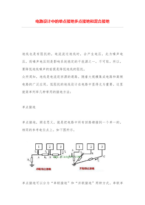
这里就简单列举几种常用的接地方法:单点接地单点接地,顾名思义,就是把电路中所有回路都接到一个单一的,相同的参考电位点上。
如下图所示。
单点接地可以分为“串联接地”和“并联接地”两种方式。
串联单点接地的方式简单,但是存在共同地线的原因,导致存在公共地线阻抗,如果此时串联在一起的是功率相差很大的电路,那么互相干扰就非常严重。
并联单点接地的方式可以避免公共地线耦合的因素,但是每部分电路都需要引地线到接地点上,需要的地线就过多,不实用。
所以,在实际应用时,可以采用串联和并联混合的单点接地方式。
在画PCB板时,把互相不易干扰的电路放一层,把互相容易发生干扰的电路放不同层,再把不同层的地并联接地。
如下图所示。
单点接地在高频电路里面,因为地线长,地线的阻抗是永远避免不了的因素,所以并不适用,那怎么办呢?下面再介绍“多点接地”。
多点接地当电路工作频率较高时,想象一下高频信号在沿着地线传播时,所到之处影响周边电路会有多么严重,因此所有电路就要就近接到地上,地线要求最短,多点接地就产生了。
多点接地,其目的是为了降低地线的阻抗,在高频(f 一定的条件下)电路中,要降低阻抗,主要从两个方面去考虑,一是减小地线电阻,二是减小地线感抗。
1,减小地线导体电阻,从电阻与横截面的关系公式中我们知道,要增加地线导通的横截面积。
但是在高频环境中,存在一种高频电流的趋肤效应(也叫集肤效应),高频电流会在导体表面通过,所以单纯增大地线导体的横截面积往往作用不大。
可以考虑在导体表面镀银,因为银的导电性较其他导电物质优秀,故而会降低导体电阻。
2,减小地线的感抗,最好的方法就是增大地线的面积。
电子电路中常见的接地问题解析

电子电路中常见的接地问题解析在电子设备的设计和使用过程中,接地问题是一个非常重要的考虑因素。
正确地处理接地问题可以确保电路的正常工作,提高设备的可靠性和稳定性。
本文将对电子电路中常见的接地问题进行解析,并提出相应的解决方案。
一、接地的基本概念在电子电路中,接地是指将电路中的某个节点与地面(地电位)相连接的过程。
接地可以实现电路的稳定工作,减少噪声和干扰,提高信号质量和设备的安全性。
常见的接地方式有单点接地、多点接地和虚接地等。
二、单点接地问题及解决方案1. 单点接地导致的问题:单点接地是指将电路中的多个节点通过一个点与地面相连接。
当电流通过该接地点时,可能会产生大量的回路电流,导致电路的干扰和共模噪声增加。
2. 解决方案:为了解决单点接地导致的问题,可以采取以下措施:(1)使用独立的接地导线连接各个节点到地面,减少共模噪声的干扰。
(2)增加滤波电容和电感器等元件,降低回路电流的干扰。
三、多点接地问题及解决方案1. 多点接地导致的问题:多点接地是指将电路中的多个节点分别与地面相连接。
当节点之间存在较大的接地电位差时,容易产生地回路电流,从而影响电路的正常工作。
2. 解决方案:为了解决多点接地导致的问题,可以采取以下措施:(1)选择合适的接地位置,使得各个节点之间的接地电位差尽可能小。
(2)适当增加滤波电容和电感器等元件,降低地回路电流的干扰。
四、虚接地问题及解决方案1. 虚接地导致的问题:虚接地是指将电路中的某个节点通过一个虚拟接地点连接到地面。
由于虚接地并非真正与地面相连,可能会产生大量的漂移电流,从而干扰电路的正常工作。
2. 解决方案:为了解决虚接地导致的问题,可以采取以下措施:(1)尽可能采用实际接地,避免使用虚接地。
(2)如果必须采用虚接地的方式,需采取补偿措施,如增加补偿电容和电感,抑制漂移电流的干扰。
综上所述,电子电路中的接地问题是设计和使用过程中需要重点考虑的因素。
正确处理接地问题可以提高电路的可靠性和稳定性,减少噪声和干扰。
PCB单点与多点接地有什么区别

接地为防止触电或保护设备的安全,把电力电讯等设备的金属底盘或外壳接
上地线;利用大地作电流回路接地线。
在电力系统中,将设备和用电装置的中性点、外壳或支架与接地装置用导体作良好的电气连接叫做接地。
接地的功用除了将一些无用的电流或是噪声干扰导入大地外,最大功用为保护使用者不被电击,以 UPS 而言,有些 UPS 会将零线与地线间的电压标示出来,确保产品不会造成对人体的电击伤害。
1.单点接地
工作频率低(<1MHz)的采用单点接地式(即把整个电路系统中的一个结构点
看作接地参考点,所有对地连接都接到这一点上,并设置一个安全接地螺栓),以防两点接地产生共地阻抗的电路性耦合。
多个电路的单点接地方式又分为串联和并联两种,由于串联接地产生共地阻抗的电路性耦合,所以低频电路最好采用并联的单点接地式。
为防止工频和其它杂散电流在信号地线上产生干扰,信号地线应与功率地线和机壳地线相绝缘。
且只在功率地线、机壳地线和接往大地的接地线的安全接地螺栓上相连(浮地式除外)。
2.多点接地
工作频率高(>30MHz)的采用多点接地式(即在该电路系统中,用一块接地平
板代替电路中每部分各自的地回路)。
因为接地引线的感抗与频率和长度成正比,工作频率高时将增加共地阻抗,从而将增大共地阻抗产生的电磁干扰,所以要求地线的长度尽量短。
采用多点接地时,尽量找最接近的低阻值接地面接地。
3.混合接地
工作频率介于1~30MHz的电路采用混合接地式。
当接地线的长度小于工作
信号波长的1/20时,采用单点接地式,否则采用多点接地式。
单点接地与多点接地简明分析
单点接地与多点接地简明分析!
首先,此处所指的“接地”不是安全接地的需要,而是电位基准参考点接地;
其次,顾名思义,单点地,是电路各接线汇接到地参考平面的一点,多点地反之;
再次,单点地要解决的问题就是针对“公共地阻抗耦合”和“低频地环路”,多点地是针对“高频所容易通过长地走线产生的共模干扰”(理论原因是显而易见的,此处略)!
6种接地
安全接地:这个大家都熟悉,略
静电接地:非导电用导体部件接地,目的之一是泄放静电、之二是阻止部件接收无线电发射机辐射能量并作二次发射!
避雷接地:就是为雷击能量提供一个向大地泄放的低阻抗接地通路! 这个大家都熟悉,略!
屏蔽接地:用作屏蔽体部件的接地! 这个在解决EMC问题方面有着十分重要的地位,涉及面也很多,以后再详细和大家讨论。
电源接地:这个严格意义上,不是什么新的接地方式,只是单独为供电电源建立基准参考0电位而已;
电路接地:这是个总的接地,该接地面,对电路所在系统的所有工作频率都呈现低阻抗特性。
小辫连接
小辫连接是将屏蔽层引到一根导线上,再通过连接器连接到地上! 这种方式在数据电缆线的屏蔽层连接上应用比较普遍。
但是在高频情况下,小辫就是一个数量级为nH的电感,另由于屏蔽层的电流的存在,因此会产生Ldi/dt的共模电压。
双绞线!
双绞线可以减小磁场和电场干扰!
减小磁场干扰:磁环路面积减小,分几种情况,1.双绞线两端在场内,那么绞接的数目并不重要,绞接的两端要尽量短,2.场沿着双绞线分布,那么绞接的数目越多越好。
这两点是比较容易理解的。
减小电场干扰:双绞线的一大特点就是使对地的共模电容平衡,从而获得较高的共模抑制比。
单点接地和 多点接地详解
接地的方法很多,具体使用那一种方法取决于系统的结构和功能。“接地”的概念首次应用在电话的设计开发中。从1881年初开始采用单根电缆为信号通道,大地为公共回路。这就是第一个接地问题。但是用大地作为信号回路会导致地回路中的过量噪声和大气干扰。为了解决这个问题,增加了信号回路线。现在存在的许多接地方法都是来源于过去成功的经验,这些方法包括:
单点接地 多点接地
单点地要解决的问题就是针对“公共地阻抗耦合”和“低频地环路”,
多点地是针对“高频所容易通过长地走线产生的共模干扰”.
低频电路中,信号的工作频率小于1MHz,它的布线和器件间的电感影响较小,而接地电路形成的环流对干扰影响较大,因而应采用一点接地。
当信号工作频率大于10MHz时,地线阻抗变得很大,此时应尽量降低地线阻抗,应采用就近多点接地。
电感成分:任何导体都有内电感(这区别于通常讲的外电感,外电感是导体所包围的面积的函数),内电感与导体所包围的面积无关。对于圆截面导体如下:
L=0.2S[ln(4.5/d) -1] (μH)
式中S=导体长度(m),d=导体直径(m)
表1说明了直流电阻与交流阻抗的巨大差异。频率很低时的阻抗可以认为是导体的电阻,从表中可以看出,随着频率升高,阻抗增加很快,当频率达到100MHz以上时,直径6.5mm长度仅为10cm的导线也有数十欧姆的阻抗。
1. 正确选择单点接地与多点接地 在低频电路中,信号的工作频率小于1MHz,它的布线和器件间的电感影响较小,而接地电路形成的环流对干扰影响较大,因而应采用一点接地。当信号工作频率大于10MHz时,地线阻抗变得很大,此时应尽量降低地线阻抗,应采用就近多点接地。高频电路宜采用多点串联接地,地线应短而租,高频元件周围尽量用栅格状大面积地箔。当工作频率在1~10MHz时,如果采用一点接地,其地线长度不应超过波长的1/20,否则应采用多点接地法。
10kV配网接地方式分析及改进措施

10kV配网接地方式分析及改进措施随着电力供应网络的不断发展,10kV配网接地方式也需要不断改进以满足新的需求和标准。
本文将分析目前常见的10kV配网接地方式,并提出一些改进措施。
目前常见的10kV配网接地方式主要有单点接地和多点接地两种方式。
单点接地方式是指将配网系统的中性点与大地相连,形成一个接地点。
多点接地方式是指在配网系统中设置多个接地点,将中性点与大地相连。
下面将从多个方面对这两种接地方式进行分析。
从接地效果来看,单点接地方式相对来说较好。
由于只有一个接地点,电流分布相对均匀,能够有效地降低电压梯度,提高系统的接地效果。
而多点接地方式由于存在多个接地点,电流分布不均匀,容易出现电压梯度过高的情况,影响接地效果。
1. 采用混合接地方式。
混合接地方式是将单点接地方式和多点接地方式相结合,既能够提高接地效果,又能够提高安全性。
可以在主接地点附近设置多个支路接地点,有效地降低电压梯度,保证系统的接地效果。
2. 加强接地系统的维护与监测。
无论采用单点接地方式还是多点接地方式,都需要定期对接地系统进行维护与监测。
及时发现接地电阻增大或者接地点故障等问题,并及时进行处理,以保证系统的正常运行和安全使用。
3. 引入智能监控系统。
利用现代智能监控技术,对配网系统的接地情况进行实时监测和分析,能够及时发现潜在的问题,并进行预警和预防措施,提高系统的安全性和可靠性。
10kV配网接地方式是非常重要的电力系统组成部分,对系统的安全性和可靠性有着重要的影响。
通过采用适当的接地方式和改进措施,能够提高系统的接地效果和安全性,保证电力系统的正常运行。
建筑电气低压配电设计中各种接地系统的探讨

建筑电气低压配电设计中各种接地系统的探讨建筑电气低压配电设计中,接地系统是非常重要的一部分,它主要用于保护人身安全和设备的正常使用。
接地系统是将电气设备等与大地相连的导体系统,以提供可靠的接地路径。
一、单点接地系统单点接地系统是指将所有的中性和金属部件连接到一个共同的接地点,这个接地点与大地之间的阻抗较低。
这种接地系统可以避免因不同接地点产生的接地电位差,保证了电流在故障时能够通过保护装置流入地面,从而保护人身安全和设备的正常使用。
多点接地系统是指在建筑内设置多个接地点,每个接地点都与大地之间的阻抗较低。
这种接地系统可以提高接地的可靠性,避免因某个接地点故障而导致整个系统失效。
多点接地系统也可以减小接地电位差,降低接地故障带来的危险。
三、接地电阻的测算在建筑电气低压配电设计中,接地电阻的测算是非常重要的一步,它决定了接地系统的质量和可靠性。
常用的测算方法有测量法、计算法和试验法等。
测量法通过实际测量接地电阻的方法来得到结果,计算法通过检查和计算每个接地元件的电阻值,然后相加得到总的接地电阻。
试验法是在工程实施过程中对接地系统进行试验,通过测量接地电阻值来验证设计的合理性。
四、不同地埋深度的影响接地系统的地埋深度也会对接地电阻产生一定的影响。
一般而言,地埋深度越大,接地电阻越小。
这是因为地埋深度的增加可以提高大地的电导率,从而减小接地电阻。
地埋深度也受到土壤类型和湿度等因素的影响,需要根据具体情况进行合理选择。
除了以上的单点接地系统和多点接地系统外,建筑电气低压配电设计中还会采用一些附加接地系统,例如防雷接地系统、电磁屏蔽接地系统等。
这些附加接地系统主要是为了保护设备免受外界干扰和雷击等因素的影响。
建筑电气低压配电设计中的接地系统是非常重要的一部分,它能够保护人身安全和设备的正常使用。
不同的接地系统及其地埋深度选择都需要根据具体情况进行合理安排,从而确保接地系统的质量和可靠性。
附加接地系统也可以进一步提高设备的防护能力。
- 1、下载文档前请自行甄别文档内容的完整性,平台不提供额外的编辑、内容补充、找答案等附加服务。
- 2、"仅部分预览"的文档,不可在线预览部分如存在完整性等问题,可反馈申请退款(可完整预览的文档不适用该条件!)。
- 3、如文档侵犯您的权益,请联系客服反馈,我们会尽快为您处理(人工客服工作时间:9:00-18:30)。
有三种基本的信号接地方式:浮地、单点接地、多点接地。
1 浮地目的:使电路或设备与公共地线可能引起环流的公共导线隔离起来,浮地还使不同电位的电路之间配合变得容易。
缺点:容易出现静电积累引起强烈的静电放电。
折衷方案:接入泄放电阻。
2 单点接地方式:线路中只有一个物理点被定义为接地参考点,凡需要接地均接于此。
缺点:不适宜用于高频场合。
3 多点接地方式:凡需要接地的点都直接连到距它最近的接地平面上,以便使接地线长度为最短。
缺点:维护较麻烦。
4 混合接地按需要选用单点及多点接地。
PCB中的大面积敷铜接地其实就是多点接地所以单面Pcb也可以实现多点接地多层PCB大多为高速电路地层的增加可以有效提高PCB的电磁兼容性是提高信号抗干扰的基本手段,同样由于电源层和底层和不同信号层的相互隔离减轻了PCB的布通率也增加了信号间的干扰。
在大功率和小功率电路混合的系统中,切忌使用,因为大功率电路中的地线电流会影响小功率电路的正常工作。
另外,最敏感的电路要放在A点,这点电位是最稳定的。
解决这个问题的方法是并联单点接地。
但是,并联单点接地需要较多的导线,实践中可以采用串联、并联混合接地。
将电路按照特性分组,相互之间不易发生干扰的电路放在同一组,相互之间容易发生干扰的电路放在不同的组。
每个组内采用串联单点接地,获得最简单的地线结构,不同组的接地采用并联单点接地,避免相互之间干扰。
这个方法的关键:绝不要使功率相差很大的电路或噪声电平相差很大的电路共用一段地线。
这些不同的地仅能在通过一点连接起来。
为了减小地线电感,在高频电路和数字电路中经常使用多点接地。
在多点接地系统中,每个电路就近接到低阻抗的地线面上,如机箱。
电路的接地线要尽量短,以减小电感。
在频率很高的系统中,通常接地线要控制在几毫米的范围内。
多点接地时容易产生公共阻抗耦合问题。
在低频的场合,通过单点接地可以解决这个问题。
但在高频时,只能通过减小地线阻抗(减小公共阻抗)来解决。
由于趋肤效应,电流仅在导体表面流动,因此增加导体的厚度并不能减小导体的电阻。
在导体表面镀银能够降低导体的电阻。
通常1MHz以下时,可以用单点接地;10MHz以上时,可以用多点接地,在1MHz和10MHz之间时,可如果最长的接地线不超过波长的1/20,可以用单点接地,否则用多点接地。
接地电容的容量一般在10nF以下,取决于需要接地的频率。
如果将设备的安全地断开,地环路就被切断,可以解决地环路电流干扰。
但是出于安全的考虑,机箱必须接到安全地上。
图中所示的接地系统解决了这个问题,对于频率较高的地环路电流,地线是断开的,而对于50Hz的交流电,机箱都是可靠接地的。
单点接地和多点接地的接地策略单点地要解决的问题就是针对“公共地阻抗耦合”和“低频地环路”,多点地是针对“高频所容易通过长地走线产生的共模干扰”.低频电路中,信号的工作频率小于1MHz,它的布线和器件间的电感影响较小,而接地电路形成的环流对干扰影响较大,因而应采用一点接地。
当信号工作频率大于10MHz时,地线阻抗变得很大,此时应尽量降低地线阻抗,应采用就近多点接地。
当工作频率在1~10MHz时,如果采用一点接地,其地线长度不应超过波长的1/20,否则应采用多点接地法。
数字地与模拟地之间单点接地,数字地之内多点接。
地线干扰与地线设计地线设计是电磁兼容设计中大家都很注意,却又不知道应该怎样去做的一个问题。
了解了地线造成干扰问题的机理之后,在设计和实施地线时就有了一个明确的思路。
本期从介绍地线造成干扰的原理入手,使读者了解设计地线的关键和原则。
1. 什么是地线?地线有安全地和信号地两种。
前者是为了保证人身安全、设备安全而设置的地线,后者是为了保证电路正确工作所设置的地线。
造成电路干扰现象的主要是信号地,因此这里仅讨论信号地的问题。
信号地的一般定义是:电路的电位参考点。
更恰当地说,这个定义是我们设计电路时的一个假设。
从这个定义是无法分析和理解一些地线干扰问题的。
从现在开始,我们在分析电磁兼容问题时,使用下面的定义。
地线是信号电流流回信号源的地阻抗路径。
既然地线是电流的一个路径,那么根据欧姆定律,地线上是有电压的;既然地线上有电压,说明地线不是一个等电位体。
这样,我们在设计电路时,关于地线电位一定的假设就不再成立,因此电路会出现各种错误。
这就是地线干扰的实质。
2. 地线的阻抗有多大?一个难以理解的问题是,我们在设计地线时,都使地线的电阻很小,那么地线上的电位差怎么会大到导致电路出错的程度。
理解这个问题,要理解地线阻抗的组成。
地线的阻抗Z 由电阻部分和感抗部分两部分组成,即:Z = RAC + jωL。
电阻成分:导体的电阻分为直流电阻RDC和交流电阻RAC。
对于交流电流,由于趋肤效应,电流集中在导体的表面,导致实际电流截面减小,电阻增加,直流电阻和交流电阻的关系如下: RAC= 0.076rf1/2RDC式中:r=导线的半径,单位cm,f=流过导线的电流频率,单位Hz, RDC= 导线的直流电阻,单位Ω。
电感成分:任何导体都有内电感(这区别于通常讲的外电感,外电感是导体所包围的面积的函数),内电感与导体所包围的面积无关。
对于圆截面导体如下: L=0.2S[ln(4.5/d) -1] (μH)式中S=导体长度(m),d=导体直径(m)表1说明了直流电阻与交流阻抗的巨大差异。
频率很低时的阻抗可以认为是导体的电阻,从表中可以看出,随着频率升高,阻抗增加很快,当频率达到100MHz以上时,直径6.5mm 长度仅为10cm的导线也有数十欧姆的阻抗。
3 地环路干扰及对策地环路干扰是一种较常见的干扰现象,常常发生在通过较长电缆连接的相距较远的设备之间。
其产生的内在原因是设备之间的地线电位差。
地线电压导致了地环路电流,由于电路的非平衡性,地环路电流导致对电路造成影响的差模干扰电压(图1)。
由于地环路干扰是由地环路电流导致的,因此在实践中,有时会发现,当将一个设备的地线断开时,干扰现象消失,这是因为地线断开时,切断了地环路。
这种现象往往发生在干扰频率较低的场合,当干扰频率高时,短开地线与否关系不大。
地环路干扰形成的原因1:两个设备的地电位不同,形成地电压,在这个电压的驱动下,“设备1-互联电缆-设备2- 地”形成的环路之间有电流流动。
由于电路的不平衡性,每根导线上的电流不同,因此会产生差模电压,对电路造成干扰。
地线上的电压是由于其他功率较大的设备也用这段地线,在地线中引起较强电流,而地线又有较大阻抗产生的。
地环路干扰形成的原因2:由于互联设备处在较强的电磁场中,电磁场在“设备1 - 互联电缆 - 设备2 - 地”形成的环路中感应出环路电流,与原因1的过程一样导致干扰。
解决地环路干扰的方法:解决地环路干扰的基本思路有三个:一个是减小地线的阻抗,从而减小干扰电压,但是这对第二种原因导致的地环路没有效果。
另一个是增加地环路的阻抗,从而减小地环路电流。
当阻抗无限大时,实际是将地环路切断,即消除了地环路。
例如将一端的设备浮地、或将线路板与机箱断开等是直接的方法。
但出于静电防护或安全的考虑,这种直接的方法在实践中往往是不允许的。
更实用的方法是使用隔离变压器、光耦合器件、共模扼流圈、平衡电路等方法。
第三个方法是改变接地结构,将一个机箱的地线连接到另一个机箱上,通过另一个机箱接地,这就是单点接地的概念。
4 公共阻抗耦合及对策当两个电路的地电流流过一个公共阻抗时,就发生了公共阻抗耦合,如图2(a) 所示。
一个电路的地电位会受到另一个电路工作状态的影响,即一个电路的地电位受另一个电路的地电流的调制,另一个电路的信号就耦合进了前一个电路。
放大器级间公共地线耦合问题:图2(a) 中的放大器,由于前置放大电路与功率放大电路共用一段地线,功率放大电路的地线电流很大,因此在地线上产生了较大的地线电压V。
这个电压正好在前置放大电路的输入回路中,如果满足一定的相位关系,就形成了正反馈,造成放大器自激。
解决办法:可以有两个解决办法,一个是将电源的位置改变一下,使它*近功率放大电路,这样,就不会有较大的地线电压落在前置放大电路的输入回路中了,如图2 (b) 所示。
另一个办法是功率放大电路单独通过一根地线连接到电源,这实际是改成了并联单点接地结构,如图2 (d) 所示。
5 接地策略信号地有图3所示的几种方式。
单点接地:所有电路的地线接到公共地线的同一点,进一步可分为串联单点接地和并联单点接地。
最大好处是没有地环路,相对简单。
但地线往往过长,导致地线阻抗过大。
多点接地:所有电路的地线就近接地,地线很短,适合高频接地。
问题是存在地环路。
混合接地:在地线系统内使用电感、电容连接,利用电感、电容器件在不同频率下有不同阻抗的特性,使地线系统在不同的频率具有不同的接地结构。
串联单点接地容易产生公共阻抗耦合的问题,解决的方法是采用并联单点接地。
但是并联单点接地往往由于地线过多,而没有可实现性。
因此,灵活的方案是,将电路按照信号特性分组,相互不会产生干扰的电路放在一组,一组内的电路采用串联单点接地,不同组的电路采用并联单点接地。
如图4所示。
这样,既解决了公共阻抗耦合的问题,又避免了地线过多的问题。
接地的方法很多,具体使用那一种方法取决于系统的结构和功能。
“接地”的概念首次应用在电话的设计开发中。
从1881年初开始采用单根电缆为信号通道,大地为公共回路。
这就是第一个接地问题。
但是用大地作为信号回路会导致地回路中的过量噪声和大气干扰。
为了解决这个问题,增加了信号回路线。
现在存在的许多接地方法都是来源于过去成功的经验,这些方法包括:1) 单点接地:如图1所示,单点接地是为许多在一起的电路提供公共电位参考点的方法,这样信号就可以在不同的电路之间传输。
若没有公共参考点,就会出现错误信号传输。
单点接地要求每个电路只接地一次,并且接在同一点。
该点常常一地球为参考。
由于只存在一个参考点,因此可以相信没有地回路存在,因而也就没有干扰问题。
2) 多点接地:如图2所示,从图中可以看出,设备内电路都以机壳为参考点,而各个设备的机壳又都以地为参考点。
这种接地结构能够提供较低的接地阻抗,这是因为多点接地时,每条地线可以很短;并且多根导线并联能够降低接地导体的总电感。
在高频电路中必须使用多点接地,并且要求每根接地线的长度小于信号波长的1/20。
3) 混合接地:混合接地既包含了单点接地的特性,又包含了多点接地的特性。
例如,系统内的电源需要单点接地,而射频信号又要求多点接地,这时就可以采用图3所示的混合接地。
对于直流,电容是开路的,电路是单点接地,对于射频,电容是导通的,电路是多点接地。
当许多相互连接的设备体积很大(设备的物理尺寸和连接电缆与任何存在的干扰信号的波长相比很大)时,就存在通过机壳和电缆的作用产生干扰的可能性。
