HP FC SAN Switch 详细配置及项目实例
华三无线v7简单配置案例解析

1. 组网需求如图1-10所示,AC旁挂在Switch上,Switch同时作为DHCP server为AP和Client 分配IP地址。
通过配置客户端在链路层使用WEP密钥12345接入无线网络。
2. 组网图图1-1 共享密钥认证配置组网图3. 配置步骤(1)创建无线服务模板# 创建无线服务模板service1。
<AC> system-view[AC] wlan service-template service1# 配置无线服务的SSID为service。
[AC-wlan-st-service1] ssid service(2)配置WEP并使能无线服务模板# 配置使用WEP40加密套件,配置密钥索引为2,使用明文的字符串12345作为共享密钥。
[AC-wlan-st-service1] cipher-suite wep40[AC-wlan-st-service1] wep key 2 wep40 pass-phrase simple 12345[AC-wlan-st-service1] wep key-id 2# 使能无线服务模板。
[AC-wlan-st-service1] service-template enable[AC-wlan-st-service1] quit(3)将无线服务模板绑定到radio1上# 创建手工AP,名称为ap1,并配置序列号。
[AC] wlan ap ap1 model WA4320i-ACN[AC-wlan-ap-ap1] serial-id 219801A0CNC138011454# 进入Radio 1视图。
[AC-wlan-ap-ap1] radio 1# 将无线服务模板绑定到Radio 1上,并开启射频。
[AC-wlan-ap-ap1-radio-1] service-template service1[AC-wlan-ap-ap1-radio-1] radio enable[AC-wlan-ap-ap1-radio-1] return4. 验证配置# 配置完成后,在AC上执行display wlan service-template命令,可以看到无线服务模板下安全信息的配置情况如下:<AC> display wlan service-template service1Service template name : service1SSID : serviceSSID-hide : DisabledUser-isolation : DisabledService template status : EnabledMaximum clients per BSS : 64Frame format : Dot3Seamless roam status : Disabled Seamless roam RSSI threshold : 50 Seamless roam RSSI gap : 20VLAN ID : 1AKM mode : Not configuredSecurity IE : Not configuredCipher suite : WEP40WEP key ID : 2TKIP countermeasure time : 0PTK lifetime : 43200 secGTK rekey : EnabledGTK rekey method : Time-basedGTK rekey time : 86400 secGTK rekey client-offline : EnabledUser authentication mode : BypassIntrusion protection : DisabledIntrusion protection mode : Temporary-blockTemporary block time : 180 secTemporary service stop time : 20 secFail VLAN ID : Not configured802.1X handshake : Disabled802.1X handshake secure : Disabled802.1X domain : Not configuredMAC-auth domain : Not configuredMax 802.1X users : 4096Max MAC-auth users : 4096802.1X re-authenticate : DisabledAuthorization fail mode : OnlineAccounting fail mode : OnlineAuthorization : PermittedKey derivation : N/APMF status : DisabledHotspot policy number : Not configuredForwarding policy status : Disabled Forwarding policy name : Not configuredFT status : DisabledQoS trust : PortQoS priority : 0(2)配置身份认证与密钥管理模式为PSK模式、加密套件为CCMP、安全信息元素为WPA并使能无线服务模板# 配置AKM为PSK,配置PSK密钥,使用明文的字符串12345678作为共享密钥。
HP-Brocade 刀片式 SAN Switch固件(FOS)升级说明-v3
第一章文档说明一、型号:此次建行全国FOS升级包括两种类型SanSwitch,4Gb和8Gb。
1.4Gb包含两种型号,只是端口License数量不同,其他一样。
1)AE372A Brocade 4/24 SAN Switch for HP c-Class BladeSystem2)AE370A Brocade 4/12 SAN Switch for HP c-Class BladeSystem2. 8Gb也有两种型号,只是端口License数量不同,其他一样。
1)AJ821A Brocade 8/24c SAN Switch for HP BladeSystem c-Class2)AJ820A Brocade 8/12c SAN Switch for HP BladeSystem c-Class二、固件(FOS)版本:【说明】重要:针对不同型号的不同固件版本,升级步骤和固件版本有区别。
主要分两大类:4Gb和8Gb。
Brocade SAN Switch的固件(FOS)不能从低版本越级升级到高版本,需要有中间版本过渡。
1.4Gb的SAN Switch统一升级到v6.2.2e。
当前运行的主要有两个版本:v5.0.x和v5.3.x(注意:此处的x代表不同的小版本)。
1)对于当前运行版本是v5.0.x的SAN Switch,请按如下版本顺序依次升级:v5.0.x -->v5.2.1b --> v5.3.1a -->v6.0.0 --> v6.1.2b --> v6.2.2e2)对于当前运行版本是v5.3.x的SAN Switch,请按如下版本顺序依次升级:v5.3.x -->v6.0.0 --> v6.1.2b --> v6.2.2e技术文档Page 1 of 153)对于除上述两种版本以外的SAN Switch,请截取上述版本顺序当中的版本进行:比如,当前如果是v6.0.x,则按照v6.0.x --> v6.1.2b --> v6.2.2e顺序进行。
Brocade SAN交换机常用配置操作指南
介绍本文档主要为大家介绍Brocade交换机常见配置操作指南。
主要内容包括:交换机命名、交换机时间配置和NTP同步、交换机状态检查、交换机启用和禁用、交换机关机操作。
更多信息自定义交换机名称:1. 使用admin用户登录交换机2. 输入switchname命令,后面加一个交换机名称。
Switch:admin> switchname newname检查交换机状态:1.使用admin用户登录交换机2.输入switchshow命令查看交换机所有端口状态3.输入switchstatusshow命令产看交换机整体状态自定义机柜名字:Brocade推荐客户为每个交换机平台自定义好机柜名字。
部分交换机日志通过机柜名字来区分设备,分配一个合理的机会名字,更有助于分析交换机日志。
所有机柜名字最长不超过15个字符,Brocade 300,5100,5300,VA-40DC,5410,5424,5450和5480这些除外(这些最长长度31个字符)。
机柜名字必须以字母开头,可以包含字母,数字,下划线。
操作步骤如下:1. 使用admin用户登录交换机2. 输入chassisname命令switch:admin> chassisname newname自定义Fabric名字:Fabric名字和fabric ID 一样用于识别和管理一个逻辑的fabric。
Fabric名字方便记忆,每个fabric名字和一个Fabric ID关联。
Fabric名字和fabric ID不冲突,分配fabric名字应注意以下事项:•每个fabric名字在机柜里面必须不能重复。
• Fabric名字长度范围是1-128个数字或者字母•所有交换机配置fabric名字要求微码版本在v7.0.0及以上。
Fabric里面可以拥有早前微码版本的交换机,但是fabric名字不会再v7.0.0以前微码上显示出来。
•配置fabric名字必须要求admin权限。
ThinkSystem DB610S 32Gb FC SAN Switch 产品指南说明书
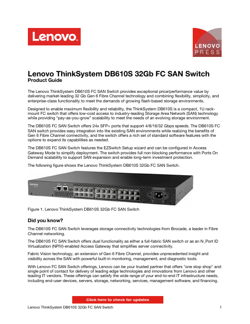
Lenovo ThinkSystem DB610S 32Gb FC SAN Switch Product GuideThe Lenovo ThinkSystem DB610S FC SAN Switch provides exceptional price/performance value by delivering market-leading 32 Gb Gen 6 Fibre Channel technology and combining flexibility, simplicity, and enterprise-class functionality to meet the demands of growing flash-based storage environments. Designed to enable maximum flexibility and reliability, the ThinkSystem DB610S is a compact, 1U rack-mount FC switch that offers low-cost access to industry-leading Storage Area Network (SAN) technology while providing “pay-as-you-grow” scalability to meet the needs of an evolving storage environment.The DB610S FC SAN Switch offers 24x SFP+ ports that support 4/8/16/32 Gbps speeds. The DB610S FC SAN switch provides easy integration into the existing SAN environments while realizing the benefits of Gen 6 Fibre Channel connectivity, and the switch offers a rich set of standard software features with the options to expand its capabilities as needed.The DB610S FC SAN Switch features the EZSwitch Setup wizard and can be configured in Access Gateway Mode to simplify deployment. The switch provides full non-blocking performance with Ports On Demand scalability to support SAN expansion and enable long-term investment protection.The following figure shows the Lenovo ThinkSystem DB610S 32Gb FC SAN Switch.Figure 1. Lenovo ThinkSystem DB610S 32Gb FC SAN SwitchDid you know?The DB610S FC SAN Switch leverages storage connectivity technologies from Brocade, a leader in Fibre Channel networking.The DB610S FC SAN Switch offers dual functionality as either a full-fabric SAN switch or as an N_Port ID Virtualization (NPIV)-enabled Access Gateway that simplifies server connectivity.Fabric Vision technology, an extension of Gen 6 Fibre Channel, provides unprecedented insight and visibility across the SAN with powerful built-in monitoring, management, and diagnostic tools.With Lenovo FC SAN Switch offerings, Lenovo can be your trusted partner that offers "one stop shop" and single point of contact for delivery of leading edge technologies and innovations from Lenovo and other leading IT vendors. These offerings can satisfy the wide range of your end-to-end IT infrastructure needs, including end-user devices, servers, storage, networking, services, management software, and financing.Click here to check for updatesFigure 2. DB610S FC SAN Switch port-side viewFigure 3. DB610S FC SAN Switch non-port-side viewSystem specificationsThe following table lists the ThinkSystem DB610S system specifications.Power supplies and cablesThe DB610S FC SAN Switch ships with one fixed 150 W AC power supply that has an IEC 309-C14 connector.The switch comes standard without a power cord; two rack power cables or country-specific line cords must be ordered together with the switch (see the following table).Table 9. Power cord optionsDescription PartnumberFeaturecodeRack power cables1.5m, 10A/100-250V, C13 to IEC 320-C14 Rack Power Cable39Y793762011.8m, 10A/100-250V, 2xC13PM to IEC 320-C14 Rack Power Cable None*65682.8m, 10A/100-250V, C13 to IEC 320-C14 Rack Power Cable4L67A083666311 2.8m, 10A/100-250V, C13 to IEC 320-C20 Rack Power Cable39Y79386204 4.3m, 10A/100-250V, C13 to IEC 320-C14 Rack Power Cable39Y79326263 Country-specific line cords10A/125V C13 to NEMA 5-15P 4.3m line cord39Y79316207 10A/250V C13 to NEMA 6-15P 2.8m line cord46M2592A1RF Argentina 10A/250V C13 to IRAM 2073 2.8m line cord39Y79306222 Australia/NZ 10A/250V C13 to AS/NZ 3112 2.8m line cord39Y79246211 Brazil 10A/125V C13 to NBR 6147 2.8m line cord39Y79296223 China 10A/250V C13 to GB 2099.1 2.8m line cord39Y79286210 Denmark 10A/250V C13 to DK2-5a 2.8m line cord39Y79186213 European 10A/230V C13 to CEE7-VII 2.8m line cord39Y79176212 India 10A/250V C13 to IS 6538 2.8m line cord39Y79276269 Israel 10A/250V C13 to SI 32 2.8m line cord39Y79206218 Italy 10A/250V C13 to CEI 23-16 2.8m line cord39Y79216217 Japan 12A/125V C13 to JIS C-8303 2.8m line cord46M2593A1RE Korea 12A/250V C13 to KETI 2.8m line cord39Y79256219 South Africa 10A/250V C13 to SABS 164 2.8m line cord39Y79226214 Switzerland 10A/250V C13 to SEV 1011-S24507 2.8m line cord39Y79196216 Taiwan 10A/250V C13 to CNS 10917-3 2.8m line cord00CG265A53E Taiwan 15A/125V C13 to CNS 10917-3 2.8m line cord00CG267A53F United Kingdom 10A/250V C13 to BS 1363/A 2.8m line cord39Y79236215 * Available for factory-built custom configurations and solutions only.Rack installationFigure 4. Lenovo DB610S Mid-mount (Telco) Rack KitPhysical specificationsThe DB610S FC SAN Switch has the following dimensions and weight (approximate): Height: 43 mm (1.7 in.)Width: 429 mm (16.9 in.)Description number Lenovo ThinkSystem DS2200 SFF FC/iSCSI Dual Controller Unit (Simplified Chinese documentation)4599A1C^ Lenovo ThinkSystem DS2200 SFF FC/iSCSI Dual Controller Unit (Japanese documentation)4599A1J** Lenovo ThinkSystem DS4200 LFF FC/iSCSI Dual Controller Unit (US English documentation)4617A31* Lenovo ThinkSystem DS4200 LFF FC/iSCSI Dual Controller Unit (Simplified Chinese documentation)4617A3C^ Lenovo ThinkSystem DS4200 LFF FC/iSCSI Dual Controller Unit (Japanese documentation)4617A3J** Lenovo ThinkSystem DS4200 SFF FC/iSCSI Dual Controller Unit (US English documentation)4617A11* Lenovo ThinkSystem DS4200 SFF FC/iSCSI Dual Controller Unit (Simplified Chinese documentation)4617A1C^ Lenovo ThinkSystem DS4200 SFF FC/iSCSI Dual Controller Unit (Japanese documentation)4617A1J** Lenovo ThinkSystem DS6200 SFF FC/iSCSI Dual Controller Unit (US English documentation)4619A11* Lenovo ThinkSystem DS6200 SFF FC/iSCSI Dual Controller Unit (Simplified Chinese documentation)4619A1C^ Lenovo ThinkSystem DS6200 SFF FC/iSCSI Dual Controller Unit (Japanese documentation)4619A1J** Lenovo Storage DX8200 Series (FC connectivity requires an optional FC HBA and a software license)Lenovo Storage DX8200D ServerSAN Entry, 8TB, 3yr SW S&S5135D2x# Lenovo Storage DX8200D ServerSAN Entry, 8TB, 4yr SW S&S5135N2x# Lenovo Storage DX8200D ServerSAN Entry, 8TB, 5yr SW S&S51354Vx# Lenovo Storage DX8200D ServerSAN Mid, 16TB, 3yr SW S&S5135F2x# Lenovo Storage DX8200D ServerSAN Mid, 16TB, 4yr SW S&S5135P2x# Lenovo Storage DX8200D ServerSAN Mid, 16TB, 5yr SW S&S51355Vx# Lenovo Storage DX8200D ServerSAN High, 32TB, 3yr SW S&S5135G2x# Lenovo Storage DX8200D ServerSAN High, 32TB, 4yr SW S&S5135Q2x# Lenovo Storage DX8200D ServerSAN High, 32TB, 5yr SW S&S51356Vx# Lenovo Storage DX8200D Storage Virtualization Entry, 4TB, 3yr SW S&S5135A2x# Lenovo Storage DX8200D Storage Virtualization Entry, 4TB, 4yr SW S&S5135J2x# Lenovo Storage DX8200D Storage Virtualization Entry, 4TB, 5yr SW S&S51351Vx# Lenovo Storage DX8200D Storage Virtualization Mid, 16TB, 3yr SW S&S5135B2x# Lenovo Storage DX8200D Storage Virtualization Mid, 16TB, 5yr SW S&S51352Vx# Lenovo Storage DX8200D Storage Virtualization Mid, 16TB, 4yr SW S&S5135L2x# Lenovo Storage DX8200D Storage Virtualization High, 64TB, 3yr SW S&S5135C2x# Lenovo Storage DX8200D Storage Virtualization High, 64TB, 4yr SW S&S5135M2x# Lenovo Storage DX8200D Storage Virtualization High, 64TB, 5yr SW S&S51353Vx# Lenovo Storage DX8200N with 1x N2226 HBA (Requires a supported external drive enclosure)5128A1x# Lenovo Storage DX8200N with 2x N2226 HBAs (Requires a supported external drive enclosure)5128A2x# Lenovo Storage S SeriesLenovo Storage S2200 LFF Chassis FC/iSCSI Single Controller, Rack Kit, 9x5NBD64114B1 Lenovo Storage S2200 LFF Chassis FC/iSCSI Dual Controller, Rack Kit, 9x5NBD64114B2 Lenovo Storage S2200 SFF Chassis FC/iSCSI Single Controller, Rack Kit, 9x5NBD64114B3 Lenovo Storage S2200 SFF Chassis FC/iSCSI Dual Controller, Rack Kit, 9x5NBD64114B4 Lenovo Storage S3200 LFF Chassis FC/iSCSI Single Controller, Rack Kit, 9x5NBD64116B1 Lenovo Storage S3200 LFF Chassis FC/iSCSI Dual Controller, Rack Kit, 9x5NBD64116B2 Lenovo Storage S3200 SFF Chassis FC/iSCSI Single Controller, Rack Kit, 9x5NBD64116B3External backup unitsThe following table lists the external backup options that are offered by Lenovo that can be used in Lenovo FC SAN solutions.Table 14. External backup optionsDescription Part numberExternal tape backup librariesIBM TS3100 Tape Library Model L2U61732UL IBM TS3200 Tape Library Model L4U61734UL Fibre Channel backup drives for TS3100 and TS3200 Tape Libraries6173 LTO Ultrium 5 Fibre Channel Drive00NA107 6173 LTO Ultrium 5 Half High Fibre Drive Sled00NA113 6173 LTO Ultrium 6 Fibre Channel Drive00NA115 6173 LTO Ultrium 6 Half High Fibre Drive Sled00NA119 6173 LTO Ultrium 7 Fibre Channel Drive00WF765 6173 LTO Ultrium 7 Half High Fibre Drive Sled00WF769For more information, see the list of Product Guides in the Backup Units category:/servers/options/backupRack cabinetsThe following table lists the rack cabinets that are offered by Lenovo that can be used in Lenovo FC SAN solutions.Table 15. Rack cabinetsDescription Part number25U S2 Standard Rack (1000 mm deep; 2 sidewall compartments)93072RX 25U Static S2 Standard Rack (1000 mm deep; 2 sidewall compartments)93072PX 42U S2 Standard Rack (1000 mm deep; 6 sidewall compartments)93074RX 42U 1100mm Enterprise V2 Dynamic Rack (6 sidewall compartments)93634PX 42U 1100mm Enterprise V2 Dynamic Expansion Rack (6 sidewall compartments)93634EX 42U 1200mm Deep Dynamic Rack (6 sidewall compartments)93604PX 42U 1200mm Deep Static Rack (6 sidewall compartments)93614PX 42U Enterprise Rack (1105 mm deep; 4 sidewall compartments)93084PX 42U Enterprise Expansion Rack (1105 mm deep; 4 sidewall compartments)93084EXFor more information, see the list of Product Guides in the Rack cabinets category:https:///servers/options/racksPower distribution unitsThe following table lists the power distribution units (PDUs) that are offered by Lenovo that can be used in Lenovo FC SAN solutions.Table 16. Power distribution unitsDescription Part number0U Basic PDUs0U 36 C13/6 C19 24A/200-240V 1 Phase PDU with NEMA L6-30P line cord00YJ776 0U 36 C13/6 C19 32A/200-240V 1 Phase PDU with IEC60309 332P6 line cord00YJ777 0U 21 C13/12 C19 32A/200-240V/346-415V 3 Phase PDU with IEC60309 532P6 line cord00YJ778 0U 21 C13/12 C19 48A/200-240V 3 Phase PDU with IEC60309 460P9 line cord00YJ779 Switched and Monitored PDUs0U 20 C13/4 C19 Switched and Monitored 24A/200-240V/1Ph PDU w/ NEMA L6-30P line cord00YJ781 0U 20 C13/4 C19 Switched and Monitored 32A/200-240V/1Ph PDU w/ IEC60309 332P6 line cord00YJ780 0U 18 C13/6 C19 Switched / Monitored 32A/200-240V/346-415V/3Ph PDU w/ IEC60309 532P6 cord00YJ782 0U 12 C13/12 C19 Switched and Monitored 48A/200-240V/3Ph PDU w/ IEC60309 460P9 line cord00YJ783 1U 9 C19/3 C13 Switched and Monitored DPI PDU (without line cord)46M4002 1U 9 C19/3 C13 Switched and Monitored 60A 3Ph PDU with IEC 309 3P+Gnd cord46M4003 1U 12 C13 Switched and Monitored DPI PDU (without line cord)46M4004 1U 12 C13 Switched and Monitored 60A 3 Phase PDU with IEC 309 3P+Gnd line cord46M4005 Ultra Density Enterprise PDUs (9x IEC 320 C13 + 3x IEC 320 C19 outlets)Ultra Density Enterprise C19/C13 PDU Module (without line cord)71762NX Ultra Density Enterprise C19/C13 PDU 60A/208V/3ph with IEC 309 3P+Gnd line cord71763NU C13 Enterprise PDUs (12x IEC 320 C13 outlets)DPI C13 Enterprise PDU+ (without line cord)39M2816 DPI Single Phase C13 Enterprise PDU (without line cord)39Y8941 C19 Enterprise PDUs (6x IEC 320 C19 outlets)DPI Single Phase C19 Enterprise PDU (without line cord)39Y8948 DPI 60A 3 Phase C19 Enterprise PDU with IEC 309 3P+G (208 V) fixed line cord39Y8923 Front-end PDUs (3x IEC 320 C19 outlets)DPI 30amp/125V Front-end PDU with NEMA L5-30P line cord39Y8938 DPI 30amp/250V Front-end PDU with NEMA L6-30P line cord39Y8939 DPI 32amp/250V Front-end PDU with IEC 309 2P+Gnd line cord39Y8934 DPI 60amp/250V Front-end PDU with IEC 309 2P+Gnd line cord39Y8940 DPI 63amp/250V Front-end PDU with IEC 309 2P+Gnd line cord39Y8935 Universal PDUs (7x IEC 320 C13 outlets)DPI Universal 7 C13 PDU (with 2 m IEC 320-C19 to C20 rack power cord)00YE443 NEMA PDUs (6x NEMA 5-15R outlets)DPI 100-127V PDU with fixed NEMA L5-15P line cord39Y8905 Line cords for PDUs that ship without a line cordDPI 30a Line Cord (NEMA L6-30P)40K9614 DPI 32a Line Cord (IEC 309 P+N+G)40K9612DPI 32a Line Cord (IEC 309 3P+N+G)40K9611DPI 60a Cord (IEC 309 2P+G)40K9615DPI 63a Cord (IEC 309 P+N+G)40K9613DPI Australian/NZ 3112 Line Cord (32A)40K9617DPI Korean 8305 Line Cord (30A)40K9618DescriptionPart number For more information, see the list of Product Guides in the PDU category:https:///servers/options/pduUninterruptible power supply unitsThe following table lists the uninterruptible power supply (UPS) units that are offered by Lenovo that can be used in Lenovo FC SAN solutions.Table 17. Uninterruptible power supply unitsDescriptionPartnumber RT1.5kVA 2U Rack or Tower UPS (100-125VAC) (8x NEMA 5-15R 12A outlets)55941AX RT1.5kVA 2U Rack or Tower UPS (200-240VAC) (8x IEC 320 C13 10A outlets)55941KX RT2.2kVA 2U Rack or Tower UPS (100-125VAC) (8x NEMA 5-20R 16A outlets)55942AX RT2.2kVA 2U Rack or Tower UPS (200-240VAC) (8x IEC 320 C13 10A, 1x IEC 320 C19 16A outlets)55942KX RT3kVA 2U Rack or Tower UPS (100-125VAC) (6x NEMA 5-20R 16A, 1x NEMA L5-30R 24A outlets)55943AX RT3kVA 2U Rack or Tower UPS (200-240VAC) (8x IEC 320 C13 10A, 1x IEC 320 C19 16A outlets)55943KX RT5kVA 3U Rack or Tower UPS (200-240VAC) (8x IEC 320 C13 10A, 2x IEC 320 C19 16A outlets)55945KX RT6kVA 3U Rack or Tower UPS (200-240VAC) (8x IEC 320 C13 10A, 2x IEC 320 C19 16A outlets)55946KX RT8kVA 6U Rack or Tower UPS (200-240VAC) (4x IEC 320-C19 16A outlets)55948KX RT11kVA 6U Rack or Tower UPS (200-240VAC) (4x IEC 320-C19 16A outlets)55949KX RT8kVA 6U 3:1 Phase Rack or Tower UPS (380-415VAC) (4x IEC 320-C19 16A outlets)55948PX RT11kVA 6U 3:1 Phase Rack or Tower UPS (380-415VAC) (4x IEC 320-C19 16A outlets)55949PXFor more information, see the list of Product Guides in the Uninterruptible Power Supply Units category:/servers/options/ups?rt=product-guideLenovo Financial ServicesTrademarksLenovo, the Lenovo logo, and For Those Who Do are trademarks or registered trademarks of Lenovo in the United States, other countries, or both. A current list of Lenovo trademarks is available on the Web at /legal/copytrade.html.The following terms are trademarks of Lenovo in the United States, other countries, or both:Lenovo®Lenovo Services™Flex System™ThinkSystem™Other company, product, or service names may be trademarks or service marks of others.。
三层交换机详细配置实例(图)
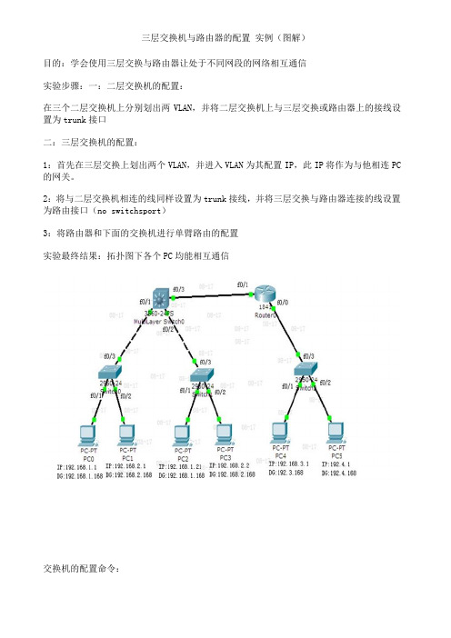
三层交换机与路由器的配置实例(图解)目的:学会使用三层交换与路由器让处于不同网段的网络相互通信实验步骤:一:二层交换机的配置:在三个二层交换机上分别划出两VLAN,并将二层交换机上与三层交换或路由器上的接线设置为trunk接口二:三层交换机的配置:1:首先在三层交换上划出两个VLAN,并进入VLAN为其配置IP,此IP将作为与他相连PC 的网关。
2:将与二层交换机相连的线同样设置为trunk接线,并将三层交换与路由器连接的线设置为路由接口(no switchsport)3:将路由器和下面的交换机进行单臂路由的配置实验最终结果:拓扑图下各个PC均能相互通信交换机的配置命令:SW 0:Switch>Switch>enSwitch#confConfiguring from terminal, memory, or network [terminal]?Enter configuration commands, one per line. End with CNTL/Z.Switch(config)#vlan 2Switch(config-vlan)#exitSwitch(config)#int f0/2Switch(config-if)#switchport access vlan 2Switch(config-if)#no shutSwitch(config-if)#int f0/3Switch(config-if)#switchport mode trunk%LINEPROTO-5-UPDOWN: Line protocol on Interface FastEthernet0/3, changed state to down%LINEPROTO-5-UPDOWN: Line protocol on Interface FastEthernet0/3, changed state to upSwitch(config-if)#exitSwitch(config)#SW 1:Switch>enSwitch#confConfiguring from terminal, memory, or network [terminal]?Enter configuration commands, one per line. End with CNTL/Z.Switch(config)#int f0/2Switch(config-if)#switchport access vlan 2% Access VLAN does not exist. Creating vlan 2Switch(config-if)#no shutSwitch(config-if)#exitSwitch(config)#int f0/3Switch(config-if)#switchport mode trunk%LINEPROTO-5-UPDOWN: Line protocol on Interface FastEthernet0/3, changed state to down%LINEPROTO-5-UPDOWN: Line protocol on Interface FastEthernet0/3, changed state to upSwitch(config-if)#SW 2:Switch>enSwitch#confConfiguring from terminal, memory, or network [terminal]?Enter configuration commands, one per line. End with CNTL/Z.Switch(config)#int f0/2Switch(config-if)#switchport access vlan 2% Access VLAN does not exist. Creating vlan 2Switch(config-if)#exitSwitch(config)#int f0/3Switch(config-if)#switchport mode trunkSwitch(config-if)#三层交换的配置命令:Switch>enSwitch#confConfiguring from terminal, memory, or network [terminal]?Enter configuration commands, one per line. End with CNTL/Z.Switch(config)#int f0/1Switch(config-if)#switchport mode trunk%LINEPROTO-5-UPDOWN: Line protocol on Interface FastEthernet0/2, changed state to downSwitch(config-if)#exitSwitch(config)#int f0/2Switch(config-if)#switchport mode trunkSwitch(config-if)#exitSwitch(config)#vlan 2Switch(config-vlan)#exitSwitch(config)#int vlan 1Switch(config-if)#no shut%LINK-5-CHANGED: Interface Vlan1, changed state to up%LINEPROTO-5-UPDOWN: Line protocol on Interface Vlan1, changed state to up Switch(config-if)#ip address 192.168.1.168 255.255.255.0Switch(config-if)#exitSwitch(config)#int vlan 2%LINK-5-CHANGED: Interface Vlan2, changed state to up%LINEPROTO-5-UPDOWN: Line protocol on Interface Vlan2, changed state to upSwitch(config-if)#ip addSwitch(config-if)#ip address 192.168.2.168 255.255.255.0Switch(config-if)#%LINK-5-CHANGED: Interface FastEthernet0/3, changed state to up%LINEPROTO-5-UPDOWN: Line protocol on Interface FastEthernet0/3, changed state to upSwitch(config-if)#exitSwitch(config)#int f0/3Switch(config-if)#no switchport%LINEPROTO-5-UPDOWN: Line protocol on Interface FastEthernet0/3, changed state to down%LINEPROTO-5-UPDOWN: Line protocol on Interface FastEthernet0/3, changed state to upSwitch(config-if)#Switch(config-if)#ip address 192.168.10.1 255.255.255.0Switch(config-if)#no shutSwitch(config-if)#exitSwitch(config)#ip routingSwitch(config-if)#exitSwitch(config)#ip route 0.0.0.0 0.0.0.0 192.168.10.2Switch(config)#路由器的配置:Router>enRouter#confConfiguring from terminal, memory, or network [terminal]?Enter configuration commands, one per line. End with CNTL/Z.Router(config)#int f0/0Router(config-if)#no shut%LINK-5-CHANGED: Interface FastEthernet0/0, changed state to upRouter(config-if)#exitRouter(config)#int f0/1Router(config-if)#no shut%LINK-5-CHANGED: Interface FastEthernet0/1, changed state to up%LINEPROTO-5-UPDOWN: Line protocol on Interface FastEthernet0/1, changed state to upRouter(config-if)#exitRouter(config)#int f0/0Router(config-if)#no shutRouter(config-if)#exitRouter(config)#int f0/0.1Router(config-subif)#encapsulation dot1Q 1Router(config-subif)#ip address 192.168.3.168 255.255.255.0Router(config-subif)#exitRouter(config)#int f0/0.2Router(config-subif)#encapsulation dot1Q 2Router(config-subif)#ip addRouter(config-subif)#ip address 192.168.4.168 255.255.255.0Router(config-subif)#exitRouter(config)#ip route 0.0.0.0 0.0.0.0 192.168.10.1Router(config)#exit%SYS-5-CONFIG_I: Configured from console by consoleRouter#confConfiguring from terminal, memory, or network [terminal]?Enter configuration commands, one per line. End with CNTL/Z.Router(config)#int f0/1Router(config-if)#ip addRouter(config-if)#ip address 192.168.10.2 255.255.255.0 Router(config-if)#。
HPSANswitch级联及ZONE的划分

HPSANswitch级联及ZONE的划分
设备:BL460 G1+B rocade 8/12c SAN Switch+ B rocade 8/24 SAN switch +MSA2324FC
1、简单拓扑连接图
使⽤的都是B系列的SAN switch,级联的时候需要注意switchdomain ID 不要冲突,然后⽤来级联的两个端⼝都会⾃适应为E-port,如下图:(本次试验使⽤超级终端的截图都是8/24 san switch 、telnet的⿊⾊截图是⼑⽚后的8/12c san switch)PORT 9 是⽤来级联san 显⽰为E-port
PORT 10 是⽤来连接MSA 2324fc,显⽰为L-port
Port 17 级联⼝E-port Port 11 连接HBA卡F-port
2、补两张使⽤nsshow 看到的信息的图
图
4、以下是试验是划分zone
因为是级联,本次试验是在8/24 SAN switch 上配置zone 信息。
alicreate 创建成员
zonecreate 创建zone
Cfgcreate
6、开启zone配置⽂件
7、保存zone配置⽂件
8、zoneshow 可以看到已经⽣效的zone和配置⽂件
9、这时候再telnet到8/12c sanSWITCH 上,可以看到配置信息已经同步过来。
如下图
总结:
本次试验级联san switch 没有划分zone 和正确的划分ZONE 之后都能正确的看到MSA2324fc上的volume。
HP SAN Switch 基本常用命令

chipregshow Displays the port registers for a given chip
number.
operations
ag Configure the Access Gateway feature
agshow Displays the Access Gateway information registered
cfgenable Enable a zone configuration
cfgremove Remove a member from a configuration
cfgsave Save zone configurations in flash
cfgshow Print zone configuration information
cfgsize Print size details of zone database
cfgtransabort Abort zone configuration transaction
bcastshow Display broadcast routing information
bladebeacon Enables or disables blade beaconing or displays the
current mode.
configuration.
authutil Get and set authentication configuration
backplanetest Backplane connection test for multi-blade systems.
HP-Brocade 刀片式 SAN Switch固件(FOS)升级说明-v3

第一章文档说明一、型号:此次建行全国FOS升级包括两种类型SanSwitch,4Gb和8Gb。
1.4Gb包含两种型号,只是端口License数量不同,其他一样。
1)AE372A Brocade 4/24 SAN Switch for HP c-Class BladeSystem2)AE370A Brocade 4/12 SAN Switch for HP c-Class BladeSystem2. 8Gb也有两种型号,只是端口License数量不同,其他一样。
1)AJ821A Brocade 8/24c SAN Switch for HP BladeSystem c-Class2)AJ820A Brocade 8/12c SAN Switch for HP BladeSystem c-Class二、固件(FOS)版本:【说明】重要:针对不同型号的不同固件版本,升级步骤和固件版本有区别。
主要分两大类:4Gb和8Gb。
Brocade SAN Switch的固件(FOS)不能从低版本越级升级到高版本,需要有中间版本过渡。
1.4Gb的SAN Switch统一升级到v6.2.2e。
当前运行的主要有两个版本:v5.0.x和v5.3.x(注意:此处的x代表不同的小版本)。
1)对于当前运行版本是v5.0.x的SAN Switch,请按如下版本顺序依次升级:v5.0.x -->v5.2.1b --> v5.3.1a -->v6.0.0 --> v6.1.2b --> v6.2.2e2)对于当前运行版本是v5.3.x的SAN Switch,请按如下版本顺序依次升级:v5.3.x -->v6.0.0 --> v6.1.2b --> v6.2.2e技术文档Page 1 of 153)对于除上述两种版本以外的SAN Switch,请截取上述版本顺序当中的版本进行:比如,当前如果是v6.0.x,则按照v6.0.x --> v6.1.2b --> v6.2.2e顺序进行。
h3c switch

(1)hybrid属性是一种混杂模式,实现了在一个untagged端口允许报文以tagged形式送出交换机。
同时可以利用hybrid属性定义分属于不同的vlan的端口之间的互访,这是access和trunk端口所不能实现的。
在一台交换机上不允许trunk端口和hybrid端口同时存在以太网端口有三种链路类型:Access、Hybrid和Trunk。
Access 类型的端口只能属于1个VLAN,一般用于连接计算机的端口;Trunk类型的端口可以属于多个VLAN,可以接收和发送多个VLAN的报文,一般用于交换机之间连接的端口;Hybrid类型的端口可以属于多个VLAN,可以接收和发送多个VLAN的报文,可以用于交换机之间连接,也可以用于连接用户的计算机。
Hybrid端口和Trunk端口的不同之处在于Hybrid端口可以允许多个VLAN的报文发送时不打标签,而Trunk端口只允许缺省VLAN的报文发送时不打标签。
:o:o:o(2)二层交换机之间实现互联一、初始化Reset save //删除保存配置Reboot //重启二、交换机之间实现互联互通登录3100,输入如下命令:System-viewInterface vlan-interface 1 //进入默认的VLAN端口,vlan 1 Ip address 192.168.1.4 24 //设置本机在VLAN 1 中的IP 地址Quitsave登录5100,输入如下命令:System-viewInterface vlan-interface 1Ip address 192.168.1.2 24Quitsave登录5600,输入如下命令:System-viewInterface vlan-interface 1Ip address 192.168.1.1 24Quitsave在3100上输入:Ping 192.168.1.1Ping 192.168.1.2同理在5100上也输入:Ping 192.168.1.1Ping 192.168.1.4同理在5600上也输入:Ping 192.168.1.2Ping 192.168.1.4至此,交换机这间的管理vlan 就可以互相通信。
HP FC SAN Switch 详细配置及项目实例

HP StorageWorks 8Gb SAN Switch配置手册及实例编辑:Windy.Chen目 录第一分部:SAN相关的重要概念第二部分,配置命令及实例第三部分: 附HP StorageWorks 8Gb SAN Switch的初始配置第四部分: 附Brocade光纤交换机划分Zone的案例及纠错第一分部:SAN相关的重要概念1,SAN是什么?SAN英文全称:Storage Area Network,即存储区域网络。
它是一种通过光纤集线器、光纤路由器、光纤交换机等连接设备将磁盘阵列、磁带等存储设备与相关服务器连接起来的高速专用子网。
SAN由三个基本的组件构成:接口(如SCSI、光纤通道、ESCON等)、连接设备(交换设备、网关、路由器、集线器等和通信控制协议(如IP和SCSI等)。
这三个组件再加上附加的存储设备和独立的SAN 服务器,就构成一个SAN系统。
SAN提供一个专用的、高可靠性的基于光通道的存储网络,SAN允许独立地增加它们的存储容量,也使得管理及集中控制(特别是对于全部存储设备都集群在一起的时候)更加简化。
而且,光纤接口提供了10 km的连接长度,这使得物理上分离的远距离存储变得更容易.SAN的一个概念是允许存储设备和处理器(服务器)之间建立直接的高速网络(与LAN相比)连接,通过这种连接实现只受光纤线路长度限制的集中式存储。
SAN可以被看作是存储总线概念的一个扩展,它使用局域网(LAN)和广域网(WAN)中类似的单元,实现存储设备和服务器之间的互连。
这些单元包括:路由器、集线器、交换机和网关。
SAN 可在服务器间共享,也可以为某一服务器所专有,既可以是本地的存储设备也可以扩展到地理区域上的其他地方。
SAN的接口可以是企业系统连接(ESCON)、小型计算机系统接口(SCSI)、串行存储结构(SSA)、高性能并行接口(HIPPI)、光纤通道(FC)或任何新的物理连接方法。
2,什么是SAN Switch?交换机是用于连接大量设备、增加带宽、减少阻塞和提供高吞吐量的一种高性能设备。
SAN Switch Zoing Configurag
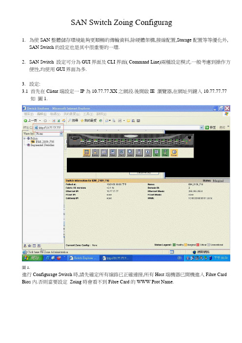
SAN Switch Zoing Configurag1.為使SAN整體儲存環境能夠更順暢的傳輸資料,除硬體架構,接線配置,Storage配置等等優化外,SAN Switch的設定也是其中很重要的一環.2.SAN Switch 設定可分為GUI界面及CLI界面( Command Line)兩種設定模式.一般考慮到操作方便性,均使用GUI界面為多.3.設定:首先在Client端設定一IP為10.77.77.XX之網段.後開啟IE 瀏覽器,在網址列鍵入10.77.77.77 如圖1.圖1.進行Configurage Switch時,請先確定所有線路已正確連接,所有Host端機器已開機進入Fibre Card Bios內.否則當要設定Zoing時會看不到Fibre Card的WWW Prot Name.3.2.進入SAN Switch後,首先要作的是將Domain ID更換掉( 兩台以上時才須更改),點選畫面中之Admin Icon進入Switch Admin模式.如圖2圖2.3.3將Switch Status Disable ,並按Apply .如圖3.圖33.4 接著更改Domain ID.如圖4圖4.3.5 更改Domain ID完畢後,退出Switch Admin模式,點左下角Zone Administrator.如圖5圖5.3.6 進入Zone Administrator後,首先點選ZONE,接著按Create 一個zone,並給予名稱,如圖6圖63.7 將左手邊所列出Switch偵測到之所有裝置加入右邊之ZONE 成員.如圖7圖7.3.8 接著點選CONFIG ,並Create 一新CONFIG ,再將左手邊之ZONE加入Config成員.如圖8,圖9圖8圖93.9 設定完成後,點選上方Actions Save Config Only將Config儲存起來。
圖103.10 最後將設定好之ZONE Config給Enable起來即完成ZONE設定。
IP Console Switches 如何配置
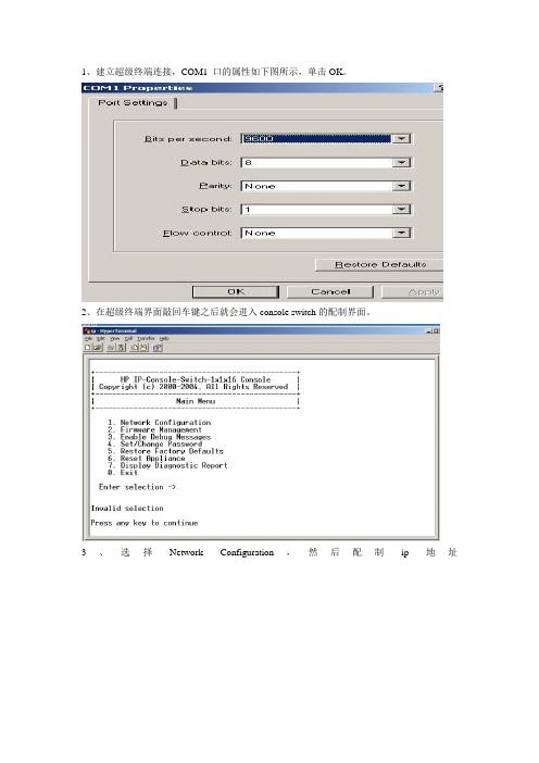
1、建立超级终端连接,COM1 口的属性如下图所示,单击OK。
2、在超级终端界面敲回车键之后就会进入console switch的配制界面。
3、选择Network Configuration,然后配制ip地址4、运行可执行程序setup HP ipconsole switch viewer程序5、开始进行安装。
6、选择english,单击OK继续7、单击Next继续8、选择I accept 单击next 继续。
9、选择安装路径继续10、选择在桌面上创建一个icon的快捷方式,单击install。
11、运行IP console switch viewer 。
12、Ip console switch view上面有四个控制按钮,分别是console switchs、Servers、Status、Folders。
上面的是程序安装以后自动运行的搜索,如果想手动运行这个程序。
可以直接双击桌面上的图标。
13、搜索IP console switch,点击Tools下面的Discover选项。
14、点击Next15、输入搜索的ip地址范围,点击Next .16、下图开始搜索。
17、搜索到一台ip console switch点击到右栏里面去就可以了。
18、单击Next继续19、单击Finish完成搜索。
20、双击这个IP console switch会打开它的配制界面。
需要输入用户名和密码,默认的用户名为Admin,密码为空。
21、如下图为Setting里面的子项。
22、下图为Tools里面的工具选项23、Upgrade console switch firmware升级firmware需要从TFTP服务器获取文件24、Upgrade interface adapter firmware也就是升级IP console switch上的一些接口的firmware。
25、保存console switch的配制,以便于以后恢复。
FC SAN和IP SAN技术介绍
FC SAN和IP SAN 技术介绍1.存储发展历程源于系统对于转发和存储的要求不断提高,存储的发展日新月异。
从最早的内置硬盘到DAS 存储,再到20世纪末出现的FC SAN以及今天已经被广泛使用的IP SAN,大型复杂的IT系统不断推动着存储架构的发展。
早期的大型服务器存储使用DAS(Direct Attached Storage),又称直连存储。
在这种方式中,存储设备是通过电缆(通常是SCSI接口电缆)直接和服务器相连。
I/O请求直接从服务器发送到存储设备。
由于早期的网络十分简单,所以直连式存储得到发展。
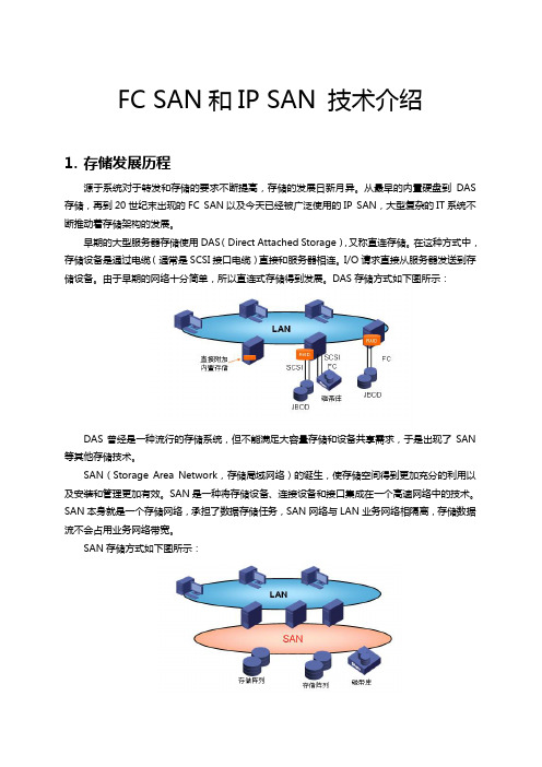
DAS存储方式如下图所示:DAS曾经是一种流行的存储系统,但不能满足大容量存储和设备共享需求,于是出现了SAN 等其他存储技术。
SAN(Storage Area Network,存储局域网络)的诞生,使存储空间得到更加充分的利用以及安装和管理更加有效。
SAN是一种将存储设备、连接设备和接口集成在一个高速网络中的技术。
SAN本身就是一个存储网络,承担了数据存储任务,SAN网络与LAN业务网络相隔离,存储数据流不会占用业务网络带宽。
SAN存储方式如下图所示:在SAN网络中,所有的数据传输在高速、高带宽的网络中进行,SAN存储实现的是直接对物理硬件的块级存储访问,提高了存储的性能和升级能力。
早期的SAN采用的是光纤通道(FC,Fiber Channel)技术,所以,以前的SAN多指采用光纤通道的存储局域网络,到了iSCSI协议出现以后,为了区分,业界就把SAN分为FC-SAN和IP-SAN。
FC和IP都是存储传输协议,二者孰优孰劣一直是业界争论的焦点。
接下来的部分将会从二者的起源、发展、协议、安全、可管理、兼容性等各方面对其进行阐述。
2.FC协议FC开发于1988年,最早是用来提高硬盘协议的传输带宽,侧重于数据的快速、高效、可靠传输。
到上世纪90年代末,FC SAN开始得到大规模的广泛应用。
FC光纤通道拥有自己的协议层,它们是:●FC-0:连接物理介质的界面、电缆等;定义编码和解码的标准。
SAN光纤交换机配置项目

请问在实施SAN的时候,光纤交换机一般都进行什么配置呢!?
一般情况下是不用设置就可以直接使用的。
但是为了配合不同的应用,也需要根据规模的不同进行设置:
一、小型的SAN,对交换机来说:
1,用串口线进去设个IP;
2,针对其应用划分ZONE;
3,调整交换机的端口类型以更好的结合应用;
4,设置其拓扑结构;
现在有的企业会有一些系统管理软件,如HP Openview, IBM Tivoli, CA TNG Unicenter等,那么这些软件能和SAN的管理集成起来吗?
答案是肯定的,我总结的方法是(2仅适用于Brocade产品):
1. Download MIB for your SAN Switch
不过我想一台SAN交换机连上去去了,如何保证它正常的运行才是最重要的。我想很多人可能觉得SAN Switch可能不是那么友好,也不知道它们平时在干嘛。
其实SAN交换机的灵魂是它的OS, 但它们的OS都比较简单,不像UNIX那么庞大,像Brocade 2xxx 系列的OS是vxworks, Brocade 3xxx,12000则有所改进,使用的是Linux的内核。和UNIX比起来SAN交换机OS的命令不算多,命令参数几乎没有多少。所以Fabric OS的管理操作应该不是问题。但我现在头疼的是很多命令返回的结果好像很复杂,乍一看根本看不懂,很多数值我也不知道有没有用。
华为华三三层交换机配置
华为华三三层交换机配置展开全文华为三层交换机配置方法(1)本文以华为华三通信的H3C S3600-28P-SI为例,配置前首先要确定型号后缀是SI还是EI,EI的支持所有协议,SI的不支持OSPS动态协议,因此SI配置路由时可以使用静态协议和RIP协议,具体配置如下:<H3C>system-view //进入系统视图[H3C]display current-configuration //显示当前配置//以下开始配置//第一步:划分VLAN,并描述vlan 1description local-S3600vlan 2description link-to-wenquanvlan 3description link-to-ruzhouvlan 4description link-to-xiaotunvlan 5description link-to-baofengvlan 6description link-to-pingxivlan 7description link-to-pingnanvlan 8description Uplink-to-Putianvlan 9description link-to-pingxicentre//第二步:给VLAN 划网关interface Vlan-interface2description link to wenquanip address 10.41.77.41 255.255.255.192 interface Vlan-interface3description link to ruzhouip address 10.41.77.105 255.255.255.192 interface Vlan-interface4description link to xiaotunip address 10.41.77.169 255.255.255.192 interface Vlan-interface5description link to baofengip address 10.41.77.233 255.255.255.192 interface Vlan-interface6description link to pingxiip address 10.41.78.41 255.255.255.192 interface Vlan-interface7description link to pingnanip address 10.41.78.105 255.255.255.192 interface Vlan-interface8description uplink to putianip address 10.41.244.102 255.255.255.252 interface Vlan-interface9description link to pingxicentreip address 10.41.80.233 255.255.255.192 //第三步:给VLAN 指定端口interface Ethernet1/0/2description link to wenquanport access vlan 2interface Ethernet1/0/3description link to ruzhouport access vlan 3interface Ethernet1/0/4description link to xiaotunport access vlan 4interface Ethernet1/0/5description link to baofengport access vlan 5interface Ethernet1/0/6description link to pingxiport access vlan 6interface Ethernet1/0/7description link to pingnanport access vlan 7interface Ethernet1/0/8description uplink to putianport access vlan 8interface Ethernet1/0/9 to Ethernet1/0/24 description link to pingxicentreport access vlan 9//第四步:配置路由协议//(1)用RIP配动态路由ripnetwork 10.41.77.41network 10.41.77.105network 10.41.77.169network 10.41.77.233network 10.41.78.41network 10.41.78.105network 10.41.80.233network 10.41.244.102//(2)配静态路由(只用对远华为三层交换机配置命令分类:默认栏目2007.6.2 07:28 作者:weiwei2501 | 评论:1 | 阅读:0Enable //进入私有模式Configure terminal //进入全局模式service password-encryption //对密码进行加密hostname Catalyst 3550-12T1 //给三层交换机定义名称enable password 123456. //enable密码Enable secret 654321 //enable的加密密码(应该是乱码而不是654321这样)Ip subnet-zero //允许使用全0子网(默认都是打开的)Ip name-server 172.16.8.1 172.16.8.2 //三层交换机名字Catalyst 3550-12T1对应的IP地址是172.16.8.1Service dhcp //提供DHCP服务ip routing //启用三层交换机上的路由模块ExitVtp mode server //定义VTP工作模式为sever模式Vtp domain centervtp //定义VTP域的名称为centervtpVlan 2 name vlan2 //定义vlan并给vlan取名(如果不取名的话,vlan2的名字应该是vlan002)Vlan 3 name vlan3Vlan 4 name vlan4Vlan 5 name vlan5Vlan 6 name vlan6Vlan 7 name vlan7Vlan 8 name vlan8Vlan 9 name vlan9Exitinterface Port-channel 1 //进入虚拟的以太通道组1Interface gigabitethernet 0/1 //进入模块0上的吉比特以太口1 channel-group 1 mode on //把这个接口放到快速以太通道组1中Interface gigabitethernet 0/2 //同上channel-group 1 mode onport-channel load-balance src-dst-ip //定义快速以太通道组的负载均衡方式(依靠源和目的IP的方式)interface gigabitethernet 0/3 //进入模块0上的吉比特以太口3interface gigabitethernet 0/4 //同上interface gigbitethernet 0/5 //同上interface gigbitethernet 0/6 //同上interface gigbitethernet 0/7 //进入模块0上的吉比特以太口7 no shutdownspanning-tree vlan 6-9 cost 1000 //在生成树中,vlan6-9的开销定义为10000interface range gigabitethernet 0/8 – 10 //进入模块0上的吉比特以太口8,9,10no shutdownspanning-tree portfast //在这些接口上使用portfast(使用portfast以后,在生成树的时候不参加运算,直接成为转发状态)interface gigabitethernet 0/11 //进入模块0上的吉比特以太口11interface gigabitethernet 0/12 //同上interface vlan 1 //进入vlan1的逻辑接口(不是物理接口,用来给vlan做路由用)ip address 172.16.1.7 255.255.255.0 //配置IP地址和子网掩码no shutdownstandby 1 ip 172.16.1.9 //开启了冗余热备份(HSRP),冗余热备份组1,虚拟路由器的IP地址为172.16.1.9standby 1 priority 110 preempt //定义这个三层交换机在冗余热备份组1中的优先级为110,preempt是用来开启抢占模式interface vlan 2 //同上ip address 172.16.2.252 255.255.255.0no shutdownstandby 2 ip 172.16.2.254standby 2 priority 110 preemptip access-group 101 in //在入方向上使用扩展的访问控制列表101interface vlan 3 //同上ip address 172.16.3.252 255.255.255.0no shutdownstandby 3 ip 172.16.3.254standby 3 priority 110 preemptip access-group 101 ininterface vlan 4 //同上ip address 172.16.4.252 255.255.255.0no shutdownstandby 4 ip 172.16.4.254standby 4 priority 110 preemptip access-group 101 ininterface vlan 5ip address 172.16.5.252 255.255.255.0 no shutdownstandby 5 ip 172.16.5.254standby 5 priority 110 preemptip access-group 101 ininterface vlan 6ip address 172.16.6.252 255.255.255.0 no shutdownstandby 6 ip 172.16.6.254standby 6 priority 100 preemptinterface vlan 7ip address 172.16.7.252 255.255.255.0 no shutdownstandby 7 ip 172.16.7.254standby 7 priority 100 preemptinterface vlan 8ip address 172.16.8.252 255.255.255.0 no shutdownstandby 8 ip 172.16.8.254standby 8 priority 100 preemptinterface vlan 9ip address 172.16.9.252 255.255.255.0 no shutdownstandby 9 ip 172.16.9.254standby 9 priority 100 preemptaccess-list 101 deny ip any 172.16.7.0 0.0.0.255 //扩展的访问控制列表101access-list 101 permit ip any anyInterface vlan 1 //进入vlan1这个逻辑接口Ip helper-address 172.16.8.1 //可以转发广播(helper-address的作用就是把广播转化为单播,然后发向172.16.8.1)Interface vlan 2Ip helper-address 172.16.8.1Interface vlan 3ip helper-address 172.16.8.1interface vlan 4ip helper-address 172.16.8.1interface vlan 5ip helper-address 172.16.8.1interface vlan 6ip helper-address 172.16.8.1interface vlan 7ip helper-address 172.16.8.1interface vlan 9ip helper-address 172.16.8.1router rip //启用路由协议RIPversion 2 //使用的是RIPv2,如果没有这句,则是使用RIPv1network 172.16.0.0 //宣告直连的网段exitip route 0.0.0.0 0.0.0.0 172.16.9.250 //缺省路由,所有在路由表中没有办法匹配的数据包,都发向下一跳地址为172.16.9.250这个路由器line con 0line aux 0line vty 0 15 //telnet线路(路由器只有5个,是0-4)password 12345678 //login密码loginendcopy running-config startup-config 保存配置cisco 3550Switch# configure terminalSwitch(config)#vtp mode transparentSwitch(config)#vlan 10Switch(config-vlan)# name vlan10Switch(config)#exitSwitch(config)#vlan 11Switch(config-vlan)name vlan11Switch(config-vlan)endSwitch#configure terminalSwitch(config)#interface fastethernet0/9Switch(config-if)#switchport mode accessSwitch(config-if)#switchport access vlan 10Switch(config-if)#exitSwitch(config)#interface fastethernet0/10Switch(config-if)#switchport mode accessSwitch(config-if)#switchport access vlan 10Switch(config-if)#exitSwitch(config)#interface fastethernet0/11Switch(config-if)#switchport mode accessSwitch(config-if)#switchport access vlan 11Switch(config-if)#exitSwitch(config)#interface fastethernet0/12Switch(config-if)#switchport mode accessSwitch(config-if)#switchport access vlan 11Switch(config-if)#exitSwitch(config)#interface vlan10Switch(config-if)#ip address 192.168.0.1 255.255.255.0Switch(config-if)#no shutdownSwitch(config-if)#exitSwitch(config)#interface vlan11Switch(config-if)#ip address 192.168.1.1 255.255.255.0Switch(config-if)#no shutdownSwitch(config-if)#exitSwitch(config)#ip routingSwitch(config)#ip forward-protocol udpSwitch(config)#inter vlan 10ip helper 172.16.11.255 //这个命令又是什么意思?是不是转发整个网段的UDP协议?为什么用到了172.16.11.255这个地址?Switch(config)#exitSwitch(config)#inter vlan 11Switch(config-if)#ip helper 172.16.10.255 //同上?Switch(config-if)#exitSwitch(config)#ip route 0.0.0.0 0.0.0.0 Vlan10Switch(config)#ip route 0.0.0.0 0.0.0.0 Vlan11Switch(config)#conf tSwitch(config)#access-list 103 permit ip 172.16.11.00.0.0.255 172.16.10.0 0.0.0.255Switch(config)#access-list 103 permit udp any any eq bootpc Switch(config)#access-list 103 permit udp any any eq tftpSwitch(config)#access-list 103 permit udp any eq bootpc any Switch(config)#access-list 103 permit udp any eq tftp anySwitch(config)#inter vlan 10Switch(config-if)#ip directed-broadcast 103 //请解释一下这个的具体含义,本人不是太明白,懂一点意思(直接广播这个列表?是不是)Switch(config-if)#exitSwitch(config)#access-list 104 permit ip 172.16.10.0 0.0.0.255 172.16.11.0 0.0.0.255Switch(config)#access-list 104 permit udp any any eq bootpc Switch(config)#access-list 104 permit udp any any eq tftpSwitch(config)#access-list 104 permit udp any eq bootpc any Switch(config)#access-list 104 permit udp any eq tftp anySwitch(config)#inter vlan 11Switch(config-if)#ip directed-broadcast 104 //同上Switch(config)#endSwitch#copy run star华为三层交换机配置实例一例华为三层交换机配置实例一例服务器1双网卡,内网IP:192.168.0.1,其它计算机通过其代理上网PORT1属于VLAN1PORT2属于VLAN2PORT3属于VLAN3VLAN1的机器可以正常上网配置VLAN2的计算机的网关为:192.168.1.254配置VLAN3的计算机的网关为:192.168.2.254即可实现VLAN间互联如果VLAN2和VLAN3的计算机要通过服务器1上网则需在三层交换机上配置默认路由系统视图下:ip route-static 0.0.0.0 0.0.0.0 192.168.0.1然后再在服务器1上配置回程路由进入命令提示符route add 192.168.1.0 255.255.255.0 192.168.0.254route add 192.168.2.0 255.255.255.0 192.168.0.254这个时候vlan2和vlan3中的计算机就可以通过服务器1访问internet了~~华为路由器与CISCO路由器在配置上的差别"华为路由器与同档次的CISCO路由器在功能特性与配置界面上完全一致,有些方面还根据国内用户的需求作了很好的改进。
实验5 实现FC SAN
实验5 实现FC SAN
一、实验目的
1.了解实现FC SAN所需的设备;
2.熟悉FC SAN的连接方式;
3.掌握FC SAN的配置方法。
二、实验内容及步骤
1、将服务器和磁盘阵列分别用连接到光纤通道交换机上。
2、将一台计算机(配置机,配置系统用)和光纤通道交换机的以太网口用网线相连。
在计算机中打开IE浏览器,输入光纤通道交换机的Web地址http://10.0.0.1。
3、输入用户名和密码登录光纤通道交换机配置界面,先创建 Zone Set,再创建Zone,并将磁盘阵列和服务器加入所创建的Zone,最后激活Zone Set,配置完成。
4、在配置机中打开IE浏览器,输入磁盘阵列Web配置地址http://10.0.0.2,输入用户名和地址,登录配置界面,先创建虚拟磁盘,然后在所创建的虚拟磁盘中创建卷,最后将卷显式映射给指定的服务器。
5、在服务器上打开磁盘管理,发现有新磁盘,对其初始化、分区、格式化。
6、通过以上配置,服务器可以通过FC SAN 访问并使用磁盘阵列上的硬盘,实现了FC SAN的配置。
三、实验要求
1.实验中仔细观察、记录、比较实验结果,如果不一致应找出原因。
2.实验中凡是需要命名的地方,均以自己名字的全拼来命名,可以用不同后缀来区分。
如张三的两台服务器可以命名为:zhangsanS1,zhangsanS2。
BrocadeSANSwitch巡检

BrocadeSANSwitch巡检Brocade SAN Switch巡检手册----------------------------------------------------------------------------------------------------------1.1Brocade设备日常状态检查用telnet工具通过Brocade 光纤交换机 IP地址登陆。
默认用户:admin,默认密码:password。
2.uptime------------显示交换机工作时间switch:admin> uptime------------------------------------------------------3.Ipaddrshow--------显示交换机IP地址信息switch:admin> ipaddrshow------------------------------------------------------4.licenseshow-------显示当前交换机所添加的license信息------------------------------------------------------5.Switchshow--------检查交换机信息及端口状态switch:admin> switchshow-------------------------------------------------------6.switchstatusshow--healthy的状态switch:user> switchstatusshow-------------------------------------------------------7.Firmwareshow------显示微码版本信息检查交换机当前微码是否符合微码评估要求,是否存在Bug,是否需要升级firmwareshow-------------------------------------------------------8.Fanshow-----------显示风扇运行状态重点检查当前交换机散热风扇状态是否为OKfanshow-------------------------------------------------------9.Tempshow----------显示交换机当前温度信息检查当前交换机的温度传感器是否为OK状态tempshow各部分温度正常(20-50度)(Absent表示插槽为空)。
fcsan用法
FCSAN用法什么是FCSAN?FCSAN(Fully Connected Storage Area Network)是一种基于全连接的存储区域网络技术。
它通过使用高速连接将存储设备连接到计算机网络,提供高性能、高可靠性的存储解决方案。
FCSAN的优势1.高性能:FCSAN使用高速连接,可以提供更高的数据传输速率和更低的延迟。
这使得在处理大量数据时,FCSAN可以提供更高的性能和吞吐量。
2.高可靠性:FCSAN通过使用冗余路径和故障转移技术来提供高可靠性。
当一个路径发生故障时,FCSAN可以自动切换到备用路径,确保数据的连续性和可用性。
3.灵活性:FCSAN可以支持多种存储设备,包括磁盘阵列、磁带库和光纤通道设备等。
这使得FCSAN可以适应不同的存储需求,并提供灵活的扩展和配置选项。
4.管理简单:FCSAN提供了一套完整的管理工具和接口,使得管理员可以方便地管理和监控存储设备。
这包括对存储设备进行配置、监控性能和故障排除等功能。
FCSAN的应用场景FCSAN广泛应用于大规模数据中心、企业级存储和云计算等场景。
以下是一些常见的应用场景:1.数据中心:FCSAN可以提供高性能、高可靠性的存储解决方案,满足数据中心对存储的高要求。
它可以用于存储大量的数据、进行数据备份和恢复等任务。
2.企业级存储:FCSAN可以为企业提供高性能、可靠的存储解决方案。
它可以用于存储企业的关键业务数据、提供高速访问和实时备份等功能。
3.云计算:FCSAN可以为云计算提供高性能、高可靠性的存储基础设施。
它可以用于存储云计算平台的虚拟机镜像、用户数据和备份等。
4.大数据分析:FCSAN可以为大数据分析提供高性能、高可靠性的存储解决方案。
它可以用于存储大规模数据集、提供高速访问和并行处理等功能。
FCSAN的部署和配置要使用FCSAN,需要进行以下步骤:1.部署存储设备:首先需要部署存储设备,包括磁盘阵列、磁带库和光纤通道设备等。
- 1、下载文档前请自行甄别文档内容的完整性,平台不提供额外的编辑、内容补充、找答案等附加服务。
- 2、"仅部分预览"的文档,不可在线预览部分如存在完整性等问题,可反馈申请退款(可完整预览的文档不适用该条件!)。
- 3、如文档侵犯您的权益,请联系客服反馈,我们会尽快为您处理(人工客服工作时间:9:00-18:30)。
HP StorageWorks 8Gb SAN Switch配置手册及实例编辑:Windy.Chen目 录第一分部:SAN相关的重要概念第二部分,配置命令及实例第三部分: 附HP StorageWorks 8Gb SAN Switch的初始配置第四部分: 附Brocade光纤交换机划分Zone的案例及纠错第一分部:SAN相关的重要概念1,SAN是什么?SAN英文全称:Storage Area Network,即存储区域网络。
它是一种通过光纤集线器、光纤路由器、光纤交换机等连接设备将磁盘阵列、磁带等存储设备与相关服务器连接起来的高速专用子网。
SAN由三个基本的组件构成:接口(如SCSI、光纤通道、ESCON等)、连接设备(交换设备、网关、路由器、集线器等和通信控制协议(如IP和SCSI等)。
这三个组件再加上附加的存储设备和独立的SAN 服务器,就构成一个SAN系统。
SAN提供一个专用的、高可靠性的基于光通道的存储网络,SAN允许独立地增加它们的存储容量,也使得管理及集中控制(特别是对于全部存储设备都集群在一起的时候)更加简化。
而且,光纤接口提供了10 km的连接长度,这使得物理上分离的远距离存储变得更容易.SAN的一个概念是允许存储设备和处理器(服务器)之间建立直接的高速网络(与LAN相比)连接,通过这种连接实现只受光纤线路长度限制的集中式存储。
SAN可以被看作是存储总线概念的一个扩展,它使用局域网(LAN)和广域网(WAN)中类似的单元,实现存储设备和服务器之间的互连。
这些单元包括:路由器、集线器、交换机和网关。
SAN 可在服务器间共享,也可以为某一服务器所专有,既可以是本地的存储设备也可以扩展到地理区域上的其他地方。
SAN的接口可以是企业系统连接(ESCON)、小型计算机系统接口(SCSI)、串行存储结构(SSA)、高性能并行接口(HIPPI)、光纤通道(FC)或任何新的物理连接方法。
2,什么是SAN Switch?交换机是用于连接大量设备、增加带宽、减少阻塞和提供高吞吐量的一种高性能设备。
3,什么是光纤交换机(FC SWITCH)?光纤通道交换机有着许多不同的功能,包括支持GBIC、冗余风扇、电源、分区、环操作和多管理接口等。
每一项功能都可以增加整个交换网络的可操作性,理解这些特点可以帮助用户设计一个功能强大的大规模的SAN。
光纤交换机的主要功能如下:自配置端口、环路设备支持、交换机级联、自适应速度检测、可配置的帧缓冲、分区(基于物理端口和基于WWN的分区)、IP over Fiber Channel(IPFC)广播、远程登录、Web管理、简单网络管理协议(SNMP)以及SCSI接口独立设备服务(SES)等。
4,什么是HBA卡和WWWN?这里所说的HBA,全称FC HBA,也就是Fiber Channel Host Bus Adapter。
在FC网络中,主机(如服务器)需要和FC网络、FC存储设备(如SAN)连接时,需要使用一种接口卡,就如同连接以太网需要以太网卡一样。
这种接口卡就叫做FC HBA,简称HBA和以太网卡的MAC地址一样,HBA上也有独一无二的标识,这就是WWN(World WideName)。
HBA上的WWN有两种:Node WWN(WWNN):每个HBA有其独有的Node WWNPort WWN(WWPN):HBA卡上每个port有其独一无二的Port WWN。
由于通讯是通过port进行的,多数情况下需要使用WWPN而不是WWNN。
WWN的长度为8bytes,用16进制表示并用冒号分隔。
例如:50:06:04:81:D6:F3:45:42在Windows 环境,有一个工具软件可是方便查询HBA卡的WWN。
FCHBA Test Tool v1.0.17.1上图的服务器上有两张HBA卡。
在SUSE9下:cat /proc/scsi/qla2xxx/1这个1可能是0,或者2,3等在SUSE10下:cat /sys/class/fc_host/host1/node_name有时会是host2或者host35,什么Domain id?domain ID来区分交换机,所以一个fabric里的交换机domain ID不能一样. 一个fabric中的多台交换机的domain ID由master交换机(默认第一个启动的交换机)自动分配。
查看命令 domainsshowswd77:admin> domainsshowNumber of domains: 116,什么是Zone在SAN 光纤交换机中zone的概念相当于以太网交换中的vlan.配置Zone需要涉及到三个对象的配置Alias,Zone,Configuration。
Alias 可以把设备的WWN或Domain,Port声明为Alias,用于更好更直观的标示设备。
使用Alias的主要目的是方便用户的使用,想象一下记住一个人的身份证号和名字的区别就可以明白其中的道理,使用Alias就想给设备启名字一样。
声明Alias的另外一个益处是便于Zone中成员的更换。
当Zone中的某个成员更换时,如果定义了Alias,只要修改Alias的定义就可以调整Zone中的成员,而不用修改Zone的配置。
Zone 区域,Zone内的设备可以相互访问,但不能访问其他Zone的设备。
Zone的成员可以有三种:“Domain,Port”;”WWN”;”Alias”。
Zone对成员的数量没有限制,可以同时有多个类型的多个设备同时存在于一个Zone中。
当一个wwn被定义在zone中后,他的所有端口都会被包括在zone中。
Configuration 在交换机上的一套关于Zone的配置,或者说一系列Zone的集合。
它可以包含一个或多个Zone作为它的成员。
在一个SAN网络中一般需要有多个Zone同时存在,这一套同时存在的Zone被存放在一个Configuration中。
为了解决在交换机上,在不同的时间有不同的Zone的配置的问题,在交换机上允许同时有多个Zone的Configuration存在方便Zone配置的切换。
所有的Configuration配置中只有一个Configuration是生效的配置,被称作Active Configuration。
其他的都是待选方案,只有在他们成为Active Configuration后,他们的Zoning配置才会生效。
在交换机上配置Zoning的主要途径有两种:Telnet和WEB TOOLS。
Zoning的配置可以动态的进行,当使用cfgEnable指定某个配置成为生效的配置后,Zoning的配置会立即在SAN网络中生效,隔离Zone间的相互访问。
在交换机上新创建Zoing的配置一般会按如下的方式进行问。
SAN交换机划分Zone的一些原则,以供参考。
01. 不同的主机操作系统划为不同的Zone.02. 磁盘设备和磁带设备划分为不同的Zone.03. 根据不同的业务也可以划分为不同的Zone.查看命令是zoneshow,下面是已经配置3个zone(maildag,bjfileserver,hypyperv)Effective configuration:cfg: bjstoragezone: maildag 50:01:43:80:05:67:01:c150:01:43:80:05:67: 01:c250:01:43:80:05:67: 01:c350:01:43:80:05:67: 01:c41,41,5zone: bjfileserver50:01:43:80:05:67: 01:c51,41,5zone: bkhyperv50:01:43:80:05:67: 01:c650:01:43:80:05:67: 01:c71,41,5第二部分,配置命令及实例前面,我们已经了解了一些基本的概念,现在就开始就结合实例来介绍一些相关命令help命令提示你如何操作。
zonehelp提示你如何操作zone。
zonecreate命令创建zone。
命令如下:zonecreate"zone_name","number;number"。
这里number可以是"域,端口号",也可以是"wwn",还可以是zone的别名和Quickloop AL_PAs。
交换机默认域为1,端口号从0-15。
可以用switchshow来查看配置。
重要的是记住必须用cfgsave保存,和cfgenable让其生效。
下面是一台24口的HP StorageWorks8Gb SAN Switch基本情况,本是有24日,但只有购买了9个模块,16个License。
swd77:admin> switchshowswitchName: swd77switchType: 71.2switchState: OnlineswitchMode: NativeswitchRole: PrincipalswitchDomain: 1switchId: fffc01switchWwn: 10:00:00:05:1e:d4:d1:01zoning: ON (bjstorage)switchBeacon: OFFArea Port Media Speed State Proto=====================================0 0 id N4 Online F-Port 50:01:43:80:05:67:01:c11 1 id N4 Online F-Port 50:01:43:80:05:67: 01:c22 2 id N4 Online F-Port 50:01:43:80:05:67: 01:c33 3 id N4 Online F-Port 50:01:43:80:05:67: 01:c44 4 id N4 Online L-Port 1 public5 5 id N4 Online L-Port 1 public6 6 id N4 Online F-Port 50:01:43:80:05:67: 01:c57 7 id N4 Online F-Port 50:01:43:80:05:67: 01:c68 8 id N4 Online F-Port 50:01:43:80:05:67: 01:c79 9 -- N8 No_Module10 10 -- N8 No_Module11 11 -- N8 No_Module12 12 -- N8 No_Module13 13 -- N8 No_Module14 14 -- N8 No_Module15 15 -- N8 No_Module16 16 -- N8 No_Module (No POD License) Disabled…….23 23 -- N8 No_Module (No POD License) Disabled在交换机的连接情况如下(有些主机有两张卡),SAN 存储是HP MSA 2312FC:下面把用命令配置方法大概列一下telnet 10.1.1.100username:adminpassword:password (默认密码)1.1 查看zone配置 (本例已经配置好)Cfgshowswd77:admin> cfgshowDefined configuration:cfg: bjstoragemaildag; bjfileserver; bjhypervzone: maildag Mailbox1a; Mailbox1b; Mailbox2a; Mailbox2b; 1,4; 1,5zone: bkfileserverbjfs01; 1,4; 1,5zone: bjhypervbjhyperv1; bjhyperv2; 1,4; 1,5alias: Mailbox1a50:01:43:80:05:67:01:c3alias: Mailbox1b50:01:43:80:05:67:01:c4alias: Mailbox2a50:01:43:80:05:67:01:c1alias: Mailbox2b50:01:43:80:05:67:01:c2alias: bjfs01 50:01:43:80:05:67:01:c5alias: bjhyperv150:01:43:80:05:67:01:c6alias: bjhyperv250:01:43:80:05:67:01:c7Effective configuration:cfg: bjstoragezone: maildag 50:01:43:80:05:67:01:c150:01:43:80:05:67: 01:c250:01:43:80:05:67: 01:c350:01:43:80:05:67: 01:c41,41,5zone: bjfileserver50:01:43:80:05:67: 01:c51,41,5zone: bkhyperv50:01:43:80:05:67: 01:c650:01:43:80:05:67: 01:c71,41,5要取消原来的配置,可先禁止配置文件(cfgdisable),删除zone(zoneremove),然后删除alias(alicremove):实现上面的配置,相关步骤如下。
