3362P精密可调电位器
LM336-2.5
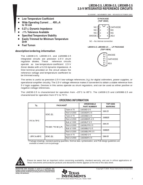
PACKAGING INFORMATION Orderable DeviceStatus (1)Package Type Package Drawing Pins Package Qty Eco Plan (2)Lead/Ball Finish MSL Peak Temp (3)LM236D-2-5ACTIVE SOIC D 875Pb-Free (RoHS)CU NIPDAU Level-2-260C-1YEAR/Level-1-235C-UNLIM LM236DR-2-5ACTIVE SOIC D 82500Pb-Free (RoHS)CU NIPDAU Level-2-260C-1YEAR/Level-1-235C-UNLIM LM236LP-2-5OBSOLETE TO-92LP 3None Call TI Call TI LM336BD-2-5ACTIVE SOIC D 875Pb-Free (RoHS)CU NIPDAU Level-2-260C-1YEAR/Level-1-235C-UNLIM LM336BDR-2-5ACTIVE SOIC D 82500Pb-Free (RoHS)CU NIPDAU Level-2-260C-1YEAR/Level-1-235C-UNLIM LM336BLP-2-5ACTIVE TO-92LP 31000None CU SNPB Level-NC-NC-NC LM336BLPR-2-5ACTIVE TO-92LP 32000None CU SNPB Level-NC-NC-NC LM336D-2-5ACTIVE SOIC D 875Pb-Free (RoHS)CU NIPDAU Level-2-260C-1YEAR/Level-1-235C-UNLIM LM336DR-2-5ACTIVE SOIC D 82500Pb-Free (RoHS)CU NIPDAU Level-2-260C-1YEAR/Level-1-235C-UNLIM LM336LP-2-5ACTIVE TO-92LP 31000None CU SNPB Level-NC-NC-NC LM336LPR-2-5ACTIVE TO-92LP 32000None CU SNPB Level-NC-NC-NC (1)The marketing status values are defined as follows:ACTIVE:Product device recommended for new designs.LIFEBUY:TI has announced that the device will be discontinued,and a lifetime-buy period is in effect.NRND:Not recommended for new designs.Device is in production to support existing customers,but TI does not recommend using this part in a new design.PREVIEW:Device has been announced but is not in production.Samples may or may not be available.OBSOLETE:TI has discontinued the production of the device.(2)Eco Plan -May not be currently available -please check /productcontent for the latest availability information and additional product content details.None:Not yet available Lead (Pb-Free).Pb-Free(RoHS):TI's terms "Lead-Free"or "Pb-Free"mean semiconductor products that are compatible with the current RoHS requirements for all 6substances,including the requirement that lead not exceed 0.1%by weight in homogeneous materials.Where designed to be soldered at high temperatures,TI Pb-Free products are suitable for use in specified lead-free processes.Green (RoHS &no Sb/Br):TI defines "Green"to mean "Pb-Free"and in addition,uses package materials that do not contain halogens,including bromine (Br)or antimony (Sb)above 0.1%of total product weight.(3)MSL,Peak Temp.--The Moisture Sensitivity Level rating according to the JEDECindustry standard classifications,and peak solder temperature.Important Information and Disclaimer:The information provided on this page represents TI's knowledge and belief as of the date that it is provided.TI bases its knowledge and belief on information provided by third parties,and makes no representation or warranty as to the accuracy of such information.Efforts are underway to better integrate information from third parties.TI has taken and continues to take reasonable steps to provide representative and accurate information but may not have conducted destructive testing or chemical analysis on incoming materials and chemicals.TI and TI suppliers consider certain information to be proprietary,and thus CAS numbers and other limited information may not be available for release.In no event shall TI's liability arising out of such information exceed the total purchase price of the TI part(s)at issue in this document sold by TI to Customer on an annual basis.PACKAGE OPTION ADDENDUM 4-Mar-2005Addendum-Page 1IMPORTANT NOTICETexas Instruments Incorporated and its subsidiaries (TI) reserve the right to make corrections, modifications, enhancements, improvements, and other changes to its products and services at any time and to discontinue any product or service without notice. Customers should obtain the latest relevant information before placing orders and should verify that such information is current and complete. All products are sold subject to TI’s terms and conditions of sale supplied at the time of order acknowledgment.TI warrants performance of its hardware products to the specifications applicable at the time of sale in accordance with TI’s standard warranty. T esting and other quality control techniques are used to the extent TI deems necessary to support this warranty. Except where mandated by government requirements, testing of all parameters of each product is not necessarily performed.TI assumes no liability for applications assistance or customer product design. Customers are responsible for their products and applications using TI components. T o minimize the risks associated with customer products and applications, customers should provide adequate design and operating safeguards.TI does not warrant or represent that any license, either express or implied, is granted under any TI patent right, copyright, mask work right, or other TI intellectual property right relating to any combination, machine, or process in which TI products or services are used. Information published by TI regarding third-party products or services does not constitute a license from TI to use such products or services or a warranty or endorsement thereof. Use of such information may require a license from a third party under the patents or other intellectual property of the third party, or a license from TI under the patents or other intellectual property of TI.Reproduction of information in TI data books or data sheets is permissible only if reproduction is without alteration and is accompanied by all associated warranties, conditions, limitations, and notices. Reproduction of this information with alteration is an unfair and deceptive business practice. TI is not responsible or liable for such altered documentation.Resale of TI products or services with statements different from or beyond the parameters stated by TI for that product or service voids all express and any implied warranties for the associated TI product or service and is an unfair and deceptive business practice. TI is not responsible or liable for any such statements. Following are URLs where you can obtain information on other Texas Instruments products and application solutions:Products ApplicationsAmplifiers Audio /audioData Converters Automotive /automotiveDSP Broadband /broadbandInterface Digital Control /digitalcontrolLogic Military /militaryPower Mgmt Optical Networking /opticalnetwork Microcontrollers Security /securityTelephony /telephonyVideo & Imaging /videoWireless /wirelessMailing Address:Texas InstrumentsPost Office Box 655303 Dallas, Texas 75265Copyright 2005, Texas Instruments Incorporated。
模拟数字器件型号大全

模拟数字器件型号⼤全型号名称1Ω电阻1.2Ω电阻1.5Ω电阻1.8Ω电阻2Ω电阻2.2Ω电阻2.4Ω电阻3.0Ω电阻3.3Ω电阻3.6Ω电阻3.9Ω电阻4.3Ω电阻4.7Ω电阻5.1Ω电阻5.6Ω电阻6.2Ω电阻6.8Ω电阻7.5Ω电阻8.2Ω电阻9.1Ω电阻10Ω电阻11Ω电阻12Ω电阻15Ω电阻18Ω电阻20Ω电阻22Ω电阻24Ω电阻27Ω电阻30Ω电阻33Ω电阻36Ω电阻39Ω电阻43Ω电阻47Ω电阻51Ω电阻56Ω电阻62Ω电阻68Ω电阻75Ω电阻82Ω电阻91Ω电阻100Ω电阻110Ω电阻120Ω电阻150Ω电阻180Ω电阻200Ω电阻220Ω电阻240Ω电阻270Ω电阻300Ω电阻330Ω电阻360Ω电阻390Ω电阻430Ω电阻470Ω电阻510Ω电阻560Ω电阻620Ω电阻680Ω电阻750Ω电阻820Ω电阻910Ω电阻1KΩ电阻1.1KΩ电阻1.2KΩ电阻1.3KΩ电阻1.5KΩ电阻1.8KΩ电阻2KΩ电阻2.2KΩ电阻2.4KΩ电阻2.7KΩ电阻3KΩ电阻3.3KΩ电阻3.6KΩ电阻3.9KΩ电阻4.3KΩ电阻4.7KΩ电阻5.1KΩ电阻5.6KΩ电阻6.2KΩ电阻6.8KΩ电阻7.5KΩ电阻8.2KΩ电阻9.1KΩ电阻10KΩ电阻11KΩ电阻12KΩ电阻15KΩ电阻18KΩ电阻20KΩ电阻24KΩ电阻27KΩ电阻30KΩ电阻33KΩ电阻36KΩ电阻39KΩ电阻43KΩ电阻47KΩ电阻51KΩ电阻56KΩ电阻62KΩ电阻68KΩ电阻75KΩ电阻82KΩ电阻91KΩ电阻100KΩ电阻110KΩ电阻120KΩ电阻150KΩ电阻180KΩ电阻200KΩ电阻220KΩ电阻240KΩ电阻270KΩ电阻300KΩ电阻330KΩ电阻360KΩ电阻390KΩ电阻430KΩ电阻470KΩ电阻510KΩ电阻560KΩ电阻620KΩ电阻680KΩ电阻750KΩ电阻820KΩ电阻910KΩ电阻1MΩ电阻1.1MΩ电阻1.2MΩ电阻1.5MΩ电阻1.8MΩ电阻2.0MΩ电阻2.2MΩ电阻2.4MΩ电阻2.7MΩ电阻3.3MΩ电阻3.6MΩ电阻3.9MΩ电阻4.7MΩ电阻5.1MΩ电阻5.6MΩ电阻6.2MΩ电阻6.8MΩ电阻7.5MΩ电阻8.2MΩ电阻9.1MΩ电阻10MΩ电阻CBB-(0.1µF/630V )CBB-(0.47µF/630V)CD-(22µF/16V)CBB(474/630)CBB-(103K/630V)CD-(100µF/25V)电解电容CD-(100µF/100V)电解电容CD-(0.47µF/50V)电解电容CD-(1µF/50V)电解电容CD-(0.1µF/50V)电解电容CD-(0.1µF/160V)电解电容CD-(2.2µF/50V)电解电容CD-(3.3µF/16V)电解电容CD-(4.7µF/250V)电解电容CD-(10µF/25V)电解电容CD-(22µF/25V)电解电容CD-(22µF/50V)电解电容CD-(22µF/250V)电解电容CD-(33µF/25V)电解电容CD-(47µF/16V)电解电容CD-(33µF/250V)电解电容CD-(47µF/63V)电解电容CD-(47µF/100V)电解电容2510-2P2510连接器VH-4P VH连接器CC-1PF瓷⽚电容CC-1.5PF瓷⽚电容CC-2.2PF瓷⽚电容CC-3PF瓷⽚电容CC-4PF瓷⽚电容CC-5.6PF瓷⽚电容CC-6PF瓷⽚电容CC-7PF瓷⽚电容CC-9PF瓷⽚电容CC-10PF瓷⽚电容CC-18PF瓷⽚电容CC-20PF瓷⽚电容CC-22PF瓷⽚电容CC-27PF瓷⽚电容CC-30PF瓷⽚电容CC-33PF瓷⽚电容CC-39PF瓷⽚电容CC-47PF瓷⽚电容CC-50PF瓷⽚电容CC-56PF瓷⽚电容CC-62PF瓷⽚电容CC-75PF瓷⽚电容CC-82PF瓷⽚电容CC-100PF瓷⽚电容CC-102瓷⽚电容CC-103瓷⽚电容CC-104瓷⽚电容CC-122瓷⽚电容CC-150PF瓷⽚电容CC-152瓷⽚电容CC-181瓷⽚电容CC-201瓷⽚电容CC-202瓷⽚电容CC-221瓷⽚电容CC-222瓷⽚电容CC-223瓷⽚电容CC-271瓷⽚电容CC-301瓷⽚电容CC-302瓷⽚电容CC-331瓷⽚电容CC-332瓷⽚电容CC-333瓷⽚电容CC-391瓷⽚电容CC-392瓷⽚电容CC-471瓷⽚电容CC-472瓷⽚电容CC-473瓷⽚电容CC-501瓷⽚电容CC-502瓷⽚电容CC-562瓷⽚电容CC-681瓷⽚电容CC-682瓷⽚电容CC-683瓷⽚电容CC-821瓷⽚电容CT-100PF独⽯电容CT-102独⽯电容CT-103独⽯电容CT-221独⽯电容CT-222独⽯电容CT-223独⽯电容CT-224独⽯电容CT-331独⽯电容CT-332独⽯电容CT-334独⽯电容CT-473独⽯电容CT-474独⽯电容CT-511独⽯电容CT-681独⽯电容CT-682独⽯电容CT-821独⽯电容CT-333独⽯电容CT-471独⽯电容CT-472独⽯电容CJ-10nF安规电容CJ-0.1µF安规电容CJ-220PF安规电容CJ-330PF安规电容LED-W-Φ3发光⼆极管(⽩)LED-R-Φ5发光⼆极管(红)LED-G-Φ5发光⼆极管(绿)CYY-25P~36P可调电容IC-8P DIP插座IC-14P DIP插座IC-16P DIP插座IC-18P DIP插座IC-20P DIP插座IC-24P DIP插座IC-28P DIP插座IC-32P DIP插座IC-40P DIP插座HY6225632K×8位COMS静态RAMHM61162K×8位⾼速CNOS SRAMM27C12816K×8位EPROMGAL20V8B可编逻辑器件PIC16C57C PIC单⽚机(EPROM/ROM的基于8位CMOS微控制器系列)PIC12C508A(⼋⾓贴⽚)PIC单⽚机(8针8位CMOS微控制器)24LC08B8K/16K串⾏EEPROMADC08098通道8位A/D转换器ADC08328位串⾏A/D转换器AD7751电能检测计量电路AD545JH精密的漂移FET输⼊运放AD57412位35µ模数转换器AD526软件编程带微机接⼝仪表放⼤器ADS774采样可控模数转换器AD620低功耗仪表放⼤器AD77052/3通道 16位∑型数模转换器DAC08328位22缓冲数模转换器AD6501MHz低线性误差压频转换器(电压⾄频率和频率对电压转换器)AD6698位8.0µS电压输出DAC(单⽚16位DACPORT)AD67716位,100千次采样/秒,采样DACAD72288位8通道AD9851直接数字频率合成器(DDS的180MHz的CMOS1DAC的合成)AD9852300MHz的CMOS完成10MH⾊环电感33MH⾊环电感1MH⾊环电感33MH⽴式电感1MH⽴式电感3.3mH1MHM-40P-S单排针M-80P-S双排针IDC-10P IDC连接管IDC-14P IDC连接管2510-5P2510连接管2510-6P2511连接管BL-8Ω扬声器HA-1锋鸣器943-1C-12DS继电器943-1C-6DS继电器G3RL-1A-E继电器5101AH-B数码管5101BH-B数码管LG3641BH数码管LG3641AH数码管12079CP45CP231TOOLP12PM30CST06074F157数据选择器MQ-4可燃⽓体传感器2SC1906硅外延平⾯2SC17902SC1971外延平⾯型(功率放⼤器频段⽆线电应⽤)2SC945硅晶体管(⾃动对焦⾼速开关放⼤器)压⼒传感器IRF540N沟道晶体管Trenchuos语⾳编程器语⾳模块T-40超声波发射R-40超声波接收交流接触器BAL-35DMD402ASSR-80表固态继电器TK-SN5CKS10A磁珠+铁⽚IDC-16P IDC连接器IDC-20P IDC连接器EP7128SLC84-15NM-40P-S单排插针M-80P-S双排插针M-40P-Z单排插座ORUN-4电池盒9V-1P电池扣ATMEGA1288位微控制器,带有128K字节在系统可编程闪存ATMEGA648位微控制器与字节的系统内可编程内存ATMEGA329位微控制器与字节的系统内可编程内存10×10cm双⾯万⽤板3cm铜螺柱2cm铜螺柱1.5cm铜螺柱1cm铜螺柱M40F-543874HC04六反相器74HC244⼋缓冲器/驱动器74HC240⼋缓冲器/驱动器74HC259⼋位地址缓存器74HC4051多路转化器/分配器74HC5958位移住寄存器/锁存器RX20-36Ω-50W线绕电阻RX20-30Ω-50W线绕电阻47K贴⽚电阻100K贴⽚电阻2KΩ贴⽚电阻10KΩ贴⽚电阻510Ω贴⽚电阻47Ω贴⽚电阻1KΩ贴⽚电阻200Ω贴⽚电阻100Ω贴⽚电阻0.01µF贴⽚电容0.001µF贴⽚电容JGX5113FOPA335单电源零漂移CMOS运放IRF530N N沟道功率场效应管IRF9530N P沟道功率场效应管IRF9540N HEXFET功率场效应管4.7mH⾊环电感6.8mH⾊环电感NRF2401A 2.5GHz单晶⽚射频收发器TLO71低噪声JFET输⼊运算放⼤器2SA1360-Y J型场效应管OPA642U宽带低失真、低增益运放HGTF10-1整流桥(单相放⼤器或硅桥)HGTF10-2 3.0A整流桥KBPC808WH5-1A型电位器KBPC310WH5-1A型电位器WH5-501WH5-1A型电位器WH5-502WH5-1A型电位器WH5-202WH5-1A型电位器WH5-203WH5-1A型电位器WH5-204WH5-1A型电位器WH5-473WH5-1A型电位器WH5-103WH5-1A型电位器WH5-104WH5-1A型电位器WH5-101WH5-1A型电位器WH5-102WH5-1A型电位器1N4728电⼒稳压⼆极管硅平⾯1N4729齐纳⼆极管1N4148⾼速⼆极管1N914⾼速开关管1N4001轴向引线恢复整流器1N4007安培同⽤整流器光敏⼆极管FR307 3.0A快速恢复整流器(⼆极管)LED-W-Φ3发光⼆极管(⽩⾊)LED-DC-Φ3发光⼆极管(双⾊)LED-Y-Φ3发光⼆极管(黄⾊)TCT40-18⼀体化超声波传感器QM-YT1CO传感器连接器排座排针10K20K504(4.7K)50K100KDB106G整流桥E62320KBPC210整流桥2W10整流桥VH-4P VH连接器2510-4P2510连接器2SC5200三联弥三型(功率放⼤器应⽤)2SA1943晶体管(功率放⼤器应⽤)温度传感器AD590双端温度传感器MQ-2烟雾传感器Pt100温度传感器RE200B热释电被动或红外传感器LM335温度传感器IN4730 3.9V稳压80M有源晶振3.579545M⽆源晶振2.4V稳压2.7V稳压36M有源晶振2AP9⾼速开关管IN60CS9011三极管CS9012三极管红外接收CS9013三极管红外发射CS9014三极管CS9015三极管CS9018三极管CS8050三极管CS8550PNP三极管2SA1301进步党平⾯硅晶体管(⾳频功率放⼤器直流直流转换器)BT33FJ 18B20从旧系统数据表VGN3020512霍尔元件3DV31光敏三极管3DV32光敏三极管49E705霍尔元件AN503霍尔元件(电视调谐控制电路)TL431AC可调试精密并联稳压管2DW233DG201模拟开关(CMOS四路SPST模拟开关)SP203硅光电池(硅栅增强型射频功率VDMOS晶体管)IRM38AP EL-1KL2红外发射SP-1KL(红外发射)光电⼆极管1A晶闸管(单硅)1A晶闸管(双硅)TAT267BP桥驱动器ST-ICL3红外接收PT-23F红外发射ST251C光电传感器HY301光电耦合EL-1KL21红外发射DS-4P拨码开关DC-1P拨位开关IDC-30P IDC连接器IDC-40P IDC连接器TIP41C功率管(互补硅功率晶体管)TIP42C功率管(中功率线性井并⽤)KSP2907IRF840N沟道增强型硅栅的TMOS功率场效应管3D01N沟道耗尽型K1120场效应管3DA8TCJ3DJ803DG130DJK2746场效应管C2073功率管(宽带:射频和⽆线)2SC3281⼤功率三极管NPN(功率晶体管)B834中功率开关管PNPD880低频压NPN2N5401硅三极管PNP(进步党⾼压晶体管)2N5551NPN型通⽤放⼤器A7733硅三极管PNPK514⼩功率三极管A940硅三极管PNPTDA2030A18W的⾼保真放⼤器和35W的驱动程序7806﹢6V稳压管7810﹢10V稳压管(7810视频接收机模块)7808﹢8V稳压管7809﹢9V稳压管7812﹢12V稳压管7815﹢15V稳压管7824﹢24V稳压管LM317 1.2V-37V三端可调稳压管7819﹢18V稳压器7905﹣5V稳压器7906﹣6V稳压管7908﹣8V稳压管7909﹣9V稳压管7912﹣12V稳压管7915﹣15V稳压管7924﹣24V稳压管LM337﹣1.2-37V三端可调稳压管CD4503六同相缓冲器3296W-101精密可调电阻(多圈微调电位器)3296W-102精密可调电阻(多圈微调电位器)3296W-103精密可调电阻(多圈微调电位器)3296W-104精密可调电阻(多圈微调电位器)3296W-203精密可调电阻(多圈微调电位器)3296W-204精密可调电阻(多圈微调电位器)3296W-253精密可调电阻(多圈微调电位器)SP-1KL红外接收⼆极管EPMT128EP1K7C144EPC2LI20配置器件系列SHT11温度传感器USB转接器(整流器组件)NTC10K±1%热敏电阻75S1热敏电阻MYG7K330压敏电阻ORD9216⼲黄管TA12互感器KEY-6⼩按钮DPL-1P拨码开关DPL-4P拨位开关2510-2P2510连接器杜邦⼝-1P杜邦⼝BPW410光敏电阻10412直流电机RT-4K热敏电阻HM1湿度模块介⼦感应模块湿度传感器HS1101湿度传感器MOC3020光耦合开关P521光耦合开关6N137单通道的⾼速光耦合器455K⽆源晶振4M⽆源晶振32.678K⽆源晶振6M⽆源晶振8M⽆源晶振10M⽆源晶振10M有源晶振1M⽆源晶振11.0592M⽆源晶振1N474415V稳压管(硅原料齐纳⼆极管)12M⽆源晶振1N4735 6.2V稳压管14.31818M⽆源晶振20M 6.2V稳压管1N4734 5.6V稳压管24M⽆源晶振24M有源晶振40M有源晶振C5V1 5.1V稳压管40M有源晶振1N4732 4.7V稳压管10245M⽆源晶振TLC2543CN12位摸/数转换器OP27超低噪声精密运放OP37超低噪声精密运放TLC1543模拟数字变换器,串⾏输⼊TLC0820A8位模拟数字变换器TLO82JFET输⼊双运放TL084JFET输⼊四运放NEC2056ULN2803AG周边⼋段驱动系列TL494开关稳压调节器TL3842电流控制器HA17324四运算放⼤器ULN2003AG周边七段驱动系列PT2272遥控解码器PT2262遥控编码CA3140单BINOS功放LF398N采样/保持电路LF347宽带JFET输⼊四运放4N25光耦器件LF356宽带JFET输⼊运放(单JFET宽带放⼤)4N35光耦器件(光敏晶体管线/数字逻辑器)6N136光耦器件LF353宽带JFET输⼊双运放LF351BIFET运放(JFET-INPUT运放)PC817PHOTOCOUPLER设备规格MAC97A6逻辑电平可控硅MC3362低功耗双变频接收机MC3372电源MC1596平衡调制解调器MC1648压控振荡器MRY634宽带精密模拟乘法器MVR1510开关模拟电源整流器NCP1050单⽚⾼电压门控振荡器的电源开关稳压器LM2676降压稳压器LVC4245⼋端⼝收发器3.3- VKMZ41磁场传感器HS0038红外接收头LM3886⾼性能⾼频功率放⼤器MOC30366引脚零交叉optoisolatorso7控硅驱动器输出MVR1660 MLT04四通道,四象限模拟乘法器MT8880ISO2-CMOS集成DTMFTranceiverTLC221TLC372双差分⽐较器THS4503全差分⽐较器TL3116⾼速低功耗精密⽐较器IRF9540P沟道功率MOSFETISPPA180TIP32A中功率线性开关TIP32C中功率线性开关ISP1420CST5112TRF63042BYGHW806电机ZYT380直流电机GY10-W3-3E4MSP430F2002RHRG3012⼆极管SN65LBC184D差动收发器瞬态电压抑制SG3525脉宽调制控制电路SP3220RS-232驱动器/接收器ST188ST278TPST330低压降稳压器TPST333低压降稳压器TPS3803-01电压检测器TRF3750⾼频率的整数N频率合成器TSAC6200TLC7135模拟数字Converters14分⼨UA733差分视频放⼤器UCC280198针连续传导模式z控制器UGN3503⽐例,线性霍尔效应传感器UCA8224094CD(100µF/16V)电解电容CD(100µF/50V)电解电容CD(220µF/16V)电解电容CD(220µF/250V)电解电容CD(330µF/16V)电解电容CD(470µF/16V)电解电容CD(470µF/25V)电解电容CD(1000µF/25V)电解电容CD(1000µF/50V)电解电容CD(2200µF/16V)电解电容CD(4700µF/16V)电解电容CD(2200µF/25V)电解电容V149-3710154电解电容V149-3910154电解电容V149-4010153电解电容P6KE200transzorb瞬态电压抑制器P6KE150transzorb瞬态电压抑制器P6KE120transzorb瞬态电压抑制器CP2-02DP2-02SA12A 5.0通过170V500W的瞬态电压抑制器P6KE911N5817肖特基⼆极管1A20、30和40输⼊电压1N5822 3.0A的肖特基整流器9012(贴⽚)贴⽚三极管(与⾮门/16进制逆变器)9013(贴⽚)贴⽚三极管(NPN硅晶体管)8550(贴⽚)贴⽚三极管8050(贴⽚)贴⽚三极管9018(贴⽚)贴⽚三极管(NPN型外延平⾯晶体管)软件盘拨码开关电容(102)贴⽚电容0805(10Ω)贴⽚电阻磁环太阳能控制板热缩管2200µF/50V、CD电解电容CD(4700µF/50V)电解电容FC-20PFC-40P电源插头电源插座9针串⼝头9孔串⼝头0.22µH贴⽚电感0.27µH贴⽚电感68µH贴⽚电感82µH贴⽚电感CD4001四⼆输⼊或⾮门CD4002双4输⼊或⾮门CD4009六缓冲期(转换-倒相)CD4011四⼆输⼊与⾮门CD4012双4输⼊与⾮门CD4013置/复位双D型触发器CD4016四双向模拟数字开关CD401710译码输出⼗进制计数器CD402014位⼆进制计数器CD4023三3输⼊与⾮门CD40247位⼆进制串⾏计数/分配器CD4026⼗进制/7段译码驱动器HEF4027置位/复位主从触发器CD4030四异或门CD404012位⼆进制计数器CD4046锁相环CD4051单8通道多路转换/分配器CD4052双4通道多路转换/分配器HCF4052双4通道多路转换/分配器TC4052双4通道多路转换/分配器CD4054四线液晶显⽰驱动器CD4055CMOS液晶显⽰驱动器CD4056BCD-7段液晶显⽰译码/驱动器CD4060⼆进制计数/分频/振荡器CD4066四双向模拟开关74LS1754D触发器74LS181运算器/函数发⽣器74LS1924位同步加减计数器74LS1934位⼆进制同步加/减计数器74LS194双向通⽤移位寄存器74LS221多谐振荡器74LS244⼋缓冲期/驱动器74LS245⼋总线收发器74LS248七段数码管译码/驱动器74LS249七段数码管译码/驱动器74LS2738D触发器74LS2809位奇偶数发⽣校验器74LS283⼆进制全加器74LS3738D锁存器74LS3748D锁存器74LS390双⼗进制计数器74LS393双4位⼆进制计数器74LS648⼋总线收发器74LS6694位加减⼆进制计数器74LS6888位数字⽐较器74HC5958位移位寄存器/锁存器74918位移位寄存器74LS06六反相缓冲期/驱动器74LS93⼆进制计数器CD4000CMOS或⾮门74LS86四2输⼊异或门74LS904位⼗进制计数器74LS9212分频计数器74LS107双JK触发器74LS112双JK触发器74LS121单稳态触发器74LS123多谐振荡器74LS125四缓冲期/驱动器74LS132四2输⼊施密特触发与⾮门74LS1383-8线译码器74LS139双2-4线译码器74LS145⼗进制译码/驱动器74LS14710-4线优先编码器74LS1488-3线优先编码器74LS15074LS1518选1数据选择器74LS153双4选1数据选择器74LS1544-16线多路分配器74LS155双2-4 线译码器74LS1604位⼆进制计数器74LS1614位⼆进制同步计数器74LS1634位⼆进制同步计数器74LS1648位移位寄存器74HC1648位移位寄存器74LS1658位移位寄存器74LS00四2输⼊与⾮门74LS01四2输⼊正与⾮门74LS02四2输⼊正与⾮门74LS04六反相器74LS07六缓冲期/驱动器74LS08四2输⼊正与门74LS10三3输⼊正与⾮门74LS13⼆施密特触发器74LS14六施密特触发器74LS20双4输⼊正与⾮门74LS21双4输⼊正与门74LS22双四输⼊正与⾮门74LS26四2输⼊与⾮门74LS27三3输⼊正或⾮门74LS308输⼊正与⾮门74LS32四2输⼊正或门74LS5738D锁存器74HC5738D锁存器74LS424-10线⼗进制译码器74LS47七段译码驱动器74LS48七段译码驱动器74LS73双JK触发器74LS74双D 触发器74LS754位双稳锁存器74LS854位幅度⽐较器MAX038⾼频信号发⽣器MAX232RS232接⼝电路MAX202RS233接⼝电路MAX2918阶低通开关电容滤波器MAX3232RS232接⼝电路MAX306CMOS模拟多路复⽤器MAX400超失调电压运放MAX503并⾏输⼊,电压输出,10位MAX437噪声放⼤器MAX542串⾏输⼊,电压输出16位MAX756升压DC-DC转换器MAX765DC-DC逆变器MAX8093引脚弹⽚机复位控制器MAX874低电压,精密电压基准MAX1626降压型DC-DC转换器MAX262有源滤波器MAX2601功率晶体管MAX2611直流到微波低噪声放⼤器MAX4106超低噪声放⼤器MAX7401开关电容滤波器MAX74215阶开关电容滤波器MAX195BMAX2978阶开关电容滤波器OPA129超低偏置电流运放OPA132⾼速FET输⼊运放3296W-502精密可调电阻3296W-503精密可调电阻3296W-504精密可调电阻3296W-501精密可调电阻3296W-201精密可调电阻3296W-202精密可调电阻DS-4P拨码开关DS-8P拨码开关L298N电机驱动芯⽚(偶全桥式驱动器)BT151单向可控管(晶闸管)BT136双向可控管(双向晶闸管)8279可编程键盘显⽰借⼝电路82C79可编程键盘显⽰借⼝电路8255可编程接⼝扩展电路82C55CMOS可编程接⼝扩展电路8253可编程间隔计时器81552K静态RAM8031MCS51系列8位单⽚机8051MCS51系列9位单⽚机AT89C514K×8位FLASH单⽚机AT90S514K×8位FLASH单⽚机AT91C524K×8位FLASH单⽚机AT92S528位微控制器AT89C20512K×8位FLASH单⽚机HY62648K×8位FLASH单⽚机MC1403精密电压基准器(2.5)MC1488RS232四线驱动器MC1489RS232A四线驱动器MC1406014位⼆进制计数器/振荡器MC14516BCP加减计数器MC145026编码器(双编码器和译码器)MC144333?位模数转换器MC145027译码器MC3486RS422/423线路接收器NE555时基电路NE556双极型双时基电路(双计时器)NE564锁相环NE567⾳频解码器/琐相环NE5532双运放NE5534单运放(低噪声运算放⼤器)MICRF002B低功率超⾼频接收器MC1496模拟乘法器(⽋平衡调制器/解调器)LM35精密温度传感器LM311单⽐较器(⾼性能电压⽐较器)LM324通⽤四运放LM336-5V基准电压电路(5.0V的参考⼆极管)LM336-2.5V基准电压电路(参考⼆极管)LM339四⽐较器LM358低功耗双运放NB7232⽆级调速开关CD4069反相器CD4071四⼆输⼊或门(四⼆输⼊缓冲系列门)CD4073三⼆输⼊或门(CMOS门电路)CD4098双单稳态触发器HEF40106密制触发器CD40192BCD可预置可逆触发器CD40193⼆进制可预置可逆触发器CD4043四或⾮R/S锁存器。
变压器监控系统图-变压器监控系统图
高频实验指导书2013版
非线性电子线路实验指导书自动化与电子信息学院实验中心实验注意事项1、本实验系统接通电源前请确保电源插座接地良好。
2、每次安装实验模块之前应确保主机箱右侧的交流开关处于断开状态。
为保险起见,建议拔下电源线后再安装实验模块。
3、安装实验模块时,模块右边的双刀双掷开关要拨上,将模板四角的螺孔和母板上的铜支柱对齐,然后用黑色接线柱固定。
确保四个接线柱要拧紧,以免造成实验模块与电源或者地接触不良。
经仔细检查后方可通电实验。
4、各实验模块上的双刀双掷开关、拨码开关、复位开关、自锁开关、手调电位器和旋转编码器均为磨损件,请不要频繁按动或旋转。
5、请勿直接用手触摸芯片、电解电容等元件,以免造成损坏。
6、各模块中的3362电位器(蓝色正方形封装)是出厂前调试使用的。
出厂后的各实验模块功能已调至最佳状态,无需另行调节这些电位器,否则将会对实验结果造成严重影响。
若已调动请尽快复原;若无法复原,请与指导老师或直接与我公司联系。
7、在关闭各模块电源之后,方可进行连线。
连线时在保证接触良好的前提下应尽量轻插轻放,检查无误后方可通电实验。
拆线时若遇到连线与孔连接过紧的情况,应用手捏住线端的金属外壳轻轻摇晃,直至连线与孔松脱,切勿旋转及用蛮力强行拔出。
8、按动开关或转动电位器时,切勿用力过猛,以免造成元件损坏。
目录仪器介绍 (1)实验一三点式正弦波振荡器 (4)实验二模拟乘法器调幅(AM、DSB、SSB) (7)实验三包络检波及同步检波实验 (13)实验四模拟乘法混频 (21)实验五模拟锁相环实验 (26)实验六正交鉴频及锁相鉴频实验 (33)仪器介绍一、信号源本实验箱提供的信号源由高频信号源和音频信号源两部分组成,两种信号源的参数如下:1)高频信号源输出频率范围:400KHz~45MHz(连续可调);频率稳定度:10E-4;输出波形:正弦波,谐波≤-30dBc;输出幅度:1mVp-p~1Vp-p(连续可调);输出阻抗:75Ω。
江苏省2022年中职职教高考 电子专业技能考试 试卷 五
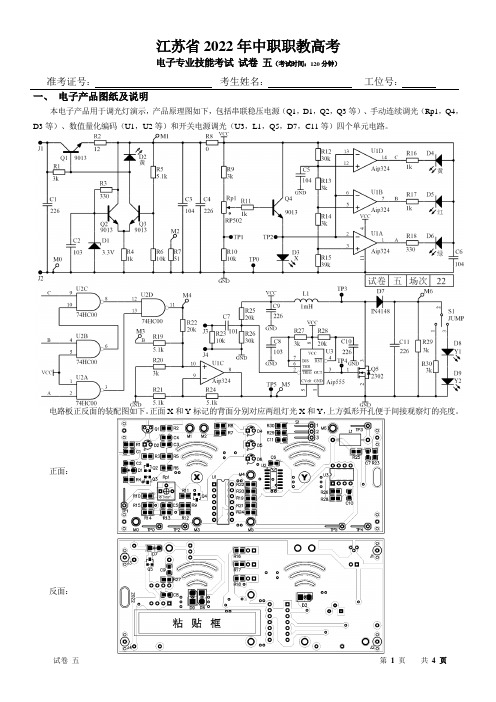
江苏省2022年中职职教高考电子专业技能考试试卷五(考试时间:120分钟)准考证号:考生姓名:工位号:一、电子产品图纸及说明本电子产品用于调光灯演示,产品原理图如下,包括串联稳压电源(Q1,D1,Q2,Q3等)、手动连续调光(Rp1,Q4,D3等)、数值量化编码(U1,U2等)和开关电源调光(U3,L1,Q5,D7,C11等)四个单元电路。
电路板正反面的装配图如下。
正面X和Y标记的背面分别对应两组灯光X和Y,上方弧形开孔便于间接观察灯的亮度。
正面:反面:二、安全文明操作要求(10分)1.遵守考场纪律,维护考场秩序,服从考场安排;2.操作符合安全规范,确保人身安全,爱惜设备器材;3.作业现场及时整理,所在工位整洁有序。
三、仪器检验(10分)开考15分钟内开机检验好工位上提供的3台仪器,确认各仪器能正常工作,调试过程中更换仪器,每台次扣2分,扣完为止。
表1 仪器清单装配焊接之前,根据表2的材料清单,清点所有材料的种类和数量。
确保各材料外观正常、数量正确,如有损坏、缺失、错漏的,应在第五项操作之前及时申请并填写错漏的材料信息,经核实后立即换发且不会扣分。
开始焊接后申请损失的元器件,待规定换发时间后,换发时每件扣1分,扣完为止。
(5分)★检测与调试答题要求:所有数值注意对应的计量单位。
用数字万用表测量的结果要求保留全部有效数字。
测量电压及电流时均默认为直流量。
当测量电位时,以GND为参考,可用M0、TP0、J2或J4点作参考点。
清点材料后,对表3涉及的5个元器件,焊接前进行识别检测,记录结果,单位填写在括号内。
(每条目2分,10分)表3 元器件识别及检测五、装配焊接(50分)对照材料清单,结合线路板正反两面的丝印装配信息,完成线路板的双面组装。
要求:1、R8暂不装焊,调试过程中装焊;2、除插件三极管外,各元器件一律贴底装焊;无错漏、无方向错误;无漏焊、虚焊、假焊、连焊;焊点和引脚加工符合装焊工艺要求;3、插件三极管整形后贴底距电路板约1mm装焊,使其顶部高度与插件发光二极管贴底装焊后的高度相当。
模拟数字器件型号大全

型号名称1Ω电阻1.2Ω电阻1.5Ω电阻1.8Ω电阻2Ω电阻2.2Ω电阻2.4Ω电阻3.0Ω电阻3.3Ω电阻3.6Ω电阻3.9Ω电阻4.3Ω电阻4.7Ω电阻5.1Ω电阻5.6Ω电阻6.2Ω电阻6.8Ω电阻7.5Ω电阻8.2Ω电阻9.1Ω电阻10Ω电阻11Ω电阻12Ω电阻15Ω电阻18Ω电阻20Ω电阻22Ω电阻24Ω电阻27Ω电阻30Ω电阻33Ω电阻36Ω电阻39Ω电阻43Ω电阻47Ω电阻51Ω电阻56Ω电阻62Ω电阻68Ω电阻75Ω电阻82Ω电阻91Ω电阻100Ω电阻110Ω电阻120Ω电阻150Ω电阻180Ω电阻200Ω电阻220Ω电阻240Ω电阻270Ω电阻300Ω电阻330Ω电阻360Ω电阻390Ω电阻430Ω电阻470Ω电阻510Ω电阻560Ω电阻620Ω电阻680Ω电阻750Ω电阻820Ω电阻910Ω电阻1KΩ电阻1.1KΩ电阻1.2KΩ电阻1.3KΩ电阻1.5KΩ电阻1.8KΩ电阻2KΩ电阻2.2KΩ电阻2.4KΩ电阻2.7KΩ电阻3KΩ电阻3.3KΩ电阻3.6KΩ电阻3.9KΩ电阻4.3KΩ电阻4.7KΩ电阻5.1KΩ电阻5.6KΩ电阻6.2KΩ电阻6.8KΩ电阻7.5KΩ电阻8.2KΩ电阻9.1KΩ电阻10KΩ电阻11KΩ电阻12KΩ电阻15KΩ电阻18KΩ电阻20KΩ电阻24KΩ电阻27KΩ电阻30KΩ电阻33KΩ电阻36KΩ电阻39KΩ电阻43KΩ电阻47KΩ电阻51KΩ电阻56KΩ电阻62KΩ电阻68KΩ电阻75KΩ电阻82KΩ电阻91KΩ电阻100KΩ电阻110KΩ电阻120KΩ电阻150KΩ电阻180KΩ电阻200KΩ电阻220KΩ电阻240KΩ电阻270KΩ电阻300KΩ电阻330KΩ电阻360KΩ电阻390KΩ电阻430KΩ电阻470KΩ电阻510KΩ电阻560KΩ电阻620KΩ电阻680KΩ电阻750KΩ电阻820KΩ电阻910KΩ电阻1MΩ电阻1.1MΩ电阻1.2MΩ电阻1.5MΩ电阻1.8MΩ电阻2.0MΩ电阻2.2MΩ电阻2.4MΩ电阻2.7MΩ电阻3.3MΩ电阻3.6MΩ电阻3.9MΩ电阻4.3MΩ电阻4.7MΩ电阻5.1MΩ电阻5.6MΩ电阻6.2MΩ电阻6.8MΩ电阻7.5MΩ电阻8.2MΩ电阻9.1MΩ电阻10MΩ电阻CBB-(0.1μF/630V )CBB-(0.47μF/630V)CD-(22μF/16V)CBB(474/630)CBB-(103K/630V)CD-(100μF/25V)电解电容CD-(100μF/100V)电解电容CD-(0.47μF/50V)电解电容CD-(1μF/50V)电解电容CD-(0.1μF/50V)电解电容CD-(0.1μF/160V)电解电容CD-(2.2μF/50V)电解电容CD-(3.3μF/16V)电解电容CD-(4.7μF/250V)电解电容CD-(10μF/25V)电解电容CD-(22μF/25V)电解电容CD-(22μF/50V)电解电容CD-(22μF/250V)电解电容CD-(33μF/25V)电解电容CD-(47μF/16V)电解电容CD-(33μF/250V)电解电容CD-(47μF/63V)电解电容CD-(47μF/100V)电解电容2510-2P2510连接器VH-4P VH连接器CC-1PF瓷片电容CC-1.5PF瓷片电容CC-2.2PF瓷片电容CC-3PF瓷片电容CC-4PF瓷片电容CC-5.6PF瓷片电容CC-6PF瓷片电容CC-7PF瓷片电容CC-9PF瓷片电容CC-10PF瓷片电容CC-18PF瓷片电容CC-20PF瓷片电容CC-22PF瓷片电容CC-27PF瓷片电容CC-30PF瓷片电容CC-33PF瓷片电容CC-39PF瓷片电容CC-47PF瓷片电容CC-50PF瓷片电容CC-56PF瓷片电容CC-62PF瓷片电容CC-75PF瓷片电容CC-82PF瓷片电容CC-100PF瓷片电容CC-102瓷片电容CC-103瓷片电容CC-104瓷片电容CC-122瓷片电容CC-150PF瓷片电容CC-152瓷片电容CC-181瓷片电容CC-201瓷片电容CC-202瓷片电容CC-221瓷片电容CC-222瓷片电容CC-223瓷片电容CC-271瓷片电容CC-301瓷片电容CC-302瓷片电容CC-331瓷片电容CC-332瓷片电容CC-333瓷片电容CC-391瓷片电容CC-392瓷片电容CC-471瓷片电容CC-472瓷片电容CC-473瓷片电容CC-501瓷片电容CC-502瓷片电容CC-562瓷片电容CC-681瓷片电容CC-682瓷片电容CC-683瓷片电容CC-821瓷片电容CT-100PF独石电容CT-102独石电容CT-103独石电容CT-221独石电容CT-222独石电容CT-223独石电容CT-224独石电容CT-331独石电容CT-332独石电容CT-334独石电容CT-473独石电容CT-474独石电容CT-511独石电容CT-561独石电容CT-681独石电容CT-682独石电容CT-821独石电容CT-333独石电容CT-471独石电容CT-472独石电容CJ-10nF安规电容CJ-0.1μF安规电容CJ-220PF安规电容CJ-330PF安规电容LED-W-Φ3发光二极管(白)LED-R-Φ5发光二极管(红)LED-G-Φ5发光二极管(绿)CYY-25P~36P可调电容IC-8P DIP插座IC-14P DIP插座IC-16P DIP插座IC-18P DIP插座IC-20P DIP插座IC-24P DIP插座IC-28P DIP插座IC-32P DIP插座IC-40P DIP插座HY6225632K×8位COMS静态RAMHM61162K×8位高速CNOS SRAMM27C12816K×8位EPROMGAL20V8B可编逻辑器件PIC16C57C PIC单片机(EPROM/ROM的基于8位CMOS微控制器系列)PIC12C508A(八角贴片)PIC单片机(8针8位CMOS微控制器)24LC08B8K/16K串行EEPROMADC08098通道8位A/D转换器ADC08328位串行A/D转换器AD7751电能检测计量电路AD545JH精密的漂移FET输入运放AD536集成真有效值直流转换器AD5708位25μSADCAD57412位35μ模数转换器AD526软件编程带微机接口仪表放大器ADS774采样可控模数转换器AD620低功耗仪表放大器AD77052/3通道 16位∑型数模转换器DAC08328位22缓冲数模转换器AD6501MHz低线性误差压频转换器(电压至频率和频率对电压转换器)AD6698位8.0μS电压输出DAC(单片16位DACPORT)AD67716位,100千次采样/秒,采样DACAD72288位8通道AD9851直接数字频率合成器(DDS的180MHz的CMOS1DAC的合成)AD9852300MHz的CMOS完成10MH色环电感33MH色环电感1MH色环电感33MH立式电感1MH立式电感3.3mH1MHM-40P-S单排针M-80P-S双排针IDC-10P IDC连接管IDC-14P IDC连接管2510-5P2510连接管2510-6P2511连接管BL-8Ω扬声器HA-1锋鸣器943-1C-12DS继电器943-1C-6DS继电器G3RL-1A-E继电器5101AH-B数码管5101BH-B数码管LG3641BH数码管LG3641AH数码管943-1C-6DS继电器G5PL-1A-E继电器12079CP45CP231TOOLP12PM30CST06074F157数据选择器MQ-4可燃气体传感器2SC1906硅外延平面2SC17902SC1971外延平面型(功率放大器频段无线电应用)2SC945硅晶体管(自动对焦高速开关放大器)压力传感器IRF540N沟道晶体管Trenchuos语音编程器语音模块T-40超声波发射R-40超声波接收交流接触器BAL-35DMD402ASSR-80表固态继电器TK-SN5CKS10A磁珠+铁片IDC-16P IDC连接器IDC-20P IDC连接器EP7128SLC84-15NM-40P-S单排插针M-80P-S双排插针M-40P-Z单排插座ORUN-4电池盒9V-1P电池扣ATMEGA1288位微控制器,带有128K字节在系统可编程闪存ATMEGA648位微控制器与字节的系统内可编程内存ATMEGA329位微控制器与字节的系统内可编程内存RS-10底座隔离控3×80mm尼龙扎带10×10cm双面万用板3cm铜螺柱2cm铜螺柱1.5cm铜螺柱1cm铜螺柱M40F-543874HC04六反相器74HC244八缓冲器/驱动器74HC240八缓冲器/驱动器74HC259八位地址缓存器74HC4051多路转化器/分配器74HC5958位移住寄存器/锁存器RX20-36Ω-50W线绕电阻RX20-30Ω-50W线绕电阻47K贴片电阻100K贴片电阻2KΩ贴片电阻10KΩ贴片电阻510Ω贴片电阻47Ω贴片电阻1KΩ贴片电阻200Ω贴片电阻100Ω贴片电阻0.01μF贴片电容0.001μF贴片电容JGX5113FOPA335单电源零漂移CMOS运放IRF530N N沟道功率场效应管IRF9530N P沟道功率场效应管IRF9540N HEXFET功率场效应管4.7mH色环电感6.8mH色环电感NRF2401A 2.5GHz单晶片射频收发器TLO71低噪声JFET输入运算放大器2SC3423-Y J型场效应管2SA1360-Y J型场效应管OPA642U宽带低失真、低增益运放HGTF10-1整流桥(单相放大器或硅桥)HGTF10-2 3.0A整流桥KBPC808WH5-1A型电位器KBPC310WH5-1A型电位器WH5-501WH5-1A型电位器WH5-502WH5-1A型电位器WH5-202WH5-1A型电位器WH5-203WH5-1A型电位器WH5-204WH5-1A型电位器WH5-473WH5-1A型电位器WH5-103WH5-1A型电位器WH5-104WH5-1A型电位器WH5-101WH5-1A型电位器WH5-102WH5-1A型电位器1N4728电力稳压二极管硅平面1N4729齐纳二极管1N4148高速二极管1N914高速开关管1N4001轴向引线恢复整流器1N4007安培同用整流器光敏二极管FR307 3.0A快速恢复整流器(二极管)LED-W-Φ3发光二极管(白色)LED-DC-Φ3发光二极管(双色)LED-Y-Φ3发光二极管(黄色)TCT40-18一体化超声波传感器QM-YT1CO传感器连接器排座排针10K20K504(4.7K)50K100K470KDB106G整流桥E62320KBPC210整流桥2W10整流桥VH-4P VH连接器2510-4P2510连接器2SC5200三联弥三型(功率放大器应用)2SA1943晶体管(功率放大器应用)温度传感器AD590双端温度传感器MQ-2烟雾传感器Pt100温度传感器RE200B热释电被动或红外传感器LM335温度传感器IN4730 3.9V稳压80M有源晶振3.579545M无源晶振2.4V稳压2.7V稳压36M有源晶振2AP9高速开关管IN60CS9011三极管CS9012三极管红外接收CS9013三极管红外发射CS9014三极管CS9015三极管CS9018三极管CS8050三极管CS8550PNP三极管2SA1301进步党平面硅晶体管(音频功率放大器直流直流转换器)BT33FJ18B20从旧系统数据表BT33PVGN3020512霍尔元件3DV31光敏三极管3DV32光敏三极管49E705霍尔元件AN503霍尔元件(电视调谐控制电路)TL431AC可调试精密并联稳压管2DW233DG201模拟开关(CMOS四路SPST模拟开关)SP203硅光电池(硅栅增强型射频功率VDMOS晶体管)IRM38APEL-1KL2红外发射SP-1KL(红外发射)光电二极管1A晶闸管(单硅)1A晶闸管(双硅)TAT267BP桥驱动器ST-ICL3红外接收PT-23F红外发射ST251C光电传感器HY301光电耦合EL-1KL21红外发射DS-4P拨码开关DC-1P拨位开关IDC-30P IDC连接器IDC-40P IDC连接器TIP41C功率管(互补硅功率晶体管)TIP42C功率管(中功率线性井并用)KSP2907IRF840N沟道增强型硅栅的TMOS功率场效应管3D01N沟道耗尽型K1120场效应管3DA8TCJ3DJ803DG130DJK2746场效应管KSP2222A通用晶体管C2073功率管(宽带:射频和无线)2SC3281大功率三极管NPN(功率晶体管)B834中功率开关管PNPD880低频压NPN2N5401硅三极管PNP(进步党高压晶体管)2N5551NPN型通用放大器A7733硅三极管PNPK514小功率三极管A940硅三极管PNPTDA2030A18W的高保真放大器和35W的驱动程序7806﹢6V稳压管7810﹢10V稳压管(7810视频接收机模块)7808﹢8V稳压管7809﹢9V稳压管7812﹢12V稳压管7815﹢15V稳压管7824﹢24V稳压管LM317 1.2V-37V三端可调稳压管7819﹢18V稳压器7905﹣5V稳压器7906﹣6V稳压管7908﹣8V稳压管7909﹣9V稳压管7912﹣12V稳压管7915﹣15V稳压管7924﹣24V稳压管LM337﹣1.2-37V三端可调稳压管CD4503六同相缓冲器3296W-101精密可调电阻(多圈微调电位器)3296W-102精密可调电阻(多圈微调电位器)3296W-103精密可调电阻(多圈微调电位器)3296W-104精密可调电阻(多圈微调电位器)3296W-203精密可调电阻(多圈微调电位器)3296W-204精密可调电阻(多圈微调电位器)3296W-253精密可调电阻(多圈微调电位器)SP-1KL红外接收二极管EPMT128EP1K7C144EPC2LI20配置器件系列SHT11温度传感器XF-18D微型话筒USB转接器(整流器组件)NTC10K±1%热敏电阻75S1热敏电阻MYG7K330压敏电阻ORD9216干黄管TA12互感器KEY-6小按钮DPL-1P拨码开关DPL-4P拨位开关2510-2P2510连接器杜邦口-1P杜邦口BPW410光敏电阻10412直流电机RT-4K热敏电阻HM1湿度模块介子感应模块湿度传感器HS1101湿度传感器MOC3020光耦合开关P521光耦合开关6N137单通道的高速光耦合器455K无源晶振4M无源晶振32.678K无源晶振6M无源晶振8M无源晶振10M无源晶振10M有源晶振1M无源晶振11.0592M无源晶振1N474415V稳压管(硅原料齐纳二极管)12M无源晶振1N4735 6.2V稳压管14.31818M无源晶振20M 6.2V稳压管1N4734 5.6V稳压管24M无源晶振24M有源晶振40M有源晶振C5V1 5.1V稳压管40M有源晶振1N4732 4.7V稳压管10245M无源晶振TLC2543CN12位摸/数转换器OP27超低噪声精密运放OP37超低噪声精密运放TLC1543模拟数字变换器,串行输入TLC0820A8位模拟数字变换器TLO82JFET输入双运放TL084JFET输入四运放NEC2056ULN2803AG周边八段驱动系列TL494开关稳压调节器TL3842电流控制器HA17324四运算放大器ULN2003AG周边七段驱动系列PT2272遥控解码器PT2262遥控编码CA3140单BINOS功放LF398N采样/保持电路LF347宽带JFET输入四运放4N25光耦器件LF356宽带JFET输入运放(单JFET宽带放大)4N35光耦器件(光敏晶体管线/数字逻辑器)6N136光耦器件LF353宽带JFET输入双运放LF351BIFET运放(JFET-INPUT运放)PC817PHOTOCOUPLER设备规格MAC97A6逻辑电平可控硅MC3362低功耗双变频接收机MC3372电源MC1596平衡调制解调器MC1648压控振荡器MRY634宽带精密模拟乘法器MVR1510开关模拟电源整流器NCP1050单片高电压门控振荡器的电源开关稳压器LM2676降压稳压器LVC4245八端口收发器3.3- VKMZ41磁场传感器HS0038红外接收头LM3886高性能高频功率放大器MOC30366引脚零交叉optoisolatorso7控硅驱动器输出MVR1660MLT04四通道,四象限模拟乘法器MT8880ISO2-CMOS集成DTMFTranceiverTLC221TLC372双差分比较器THS4503全差分比较器TL3116高速低功耗精密比较器IRF9540P沟道功率MOSFETISPPA180TIP32A中功率线性开关TIP32C中功率线性开关ISP1420CST5112TRF63042BYGHW806电机ZYT380直流电机GY10-W3-3E4MSP430F2002RHRG3012二极管SN65LBC184D差动收发器瞬态电压抑制SG3525脉宽调制控制电路SP3220RS-232驱动器/接收器ST188ST278TPST330低压降稳压器TPST333低压降稳压器TPS3803-01电压检测器TRF3750高频率的整数N频率合成器TSAC6200TLC7135模拟数字Converters14分寸UA733差分视频放大器UCC280198针连续传导模式z控制器UGN3503比例,线性霍尔效应传感器UCA8224094CD(100μF/16V)电解电容CD(100μF/50V)电解电容CD(220μF/16V)电解电容CD(220μF/250V)电解电容CD(330μF/16V)电解电容CD(470μF/16V)电解电容CD(470μF/25V)电解电容CD(1000μF/25V)电解电容CD(1000μF/50V)电解电容CD(2200μF/16V)电解电容CD(4700μF/16V)电解电容CD(2200μF/25V)电解电容V149-3710154电解电容V149-3910154电解电容V149-4010153电解电容P6KE200transzorb瞬态电压抑制器P6KE150transzorb瞬态电压抑制器P6KE120transzorb瞬态电压抑制器CP2-02DP2-02SA12A 5.0通过170V500W的瞬态电压抑制器P6KE911N5817肖特基二极管1A20、30和40输入电压1N5822 3.0A的肖特基整流器9012(贴片)贴片三极管(与非门/16进制逆变器)9013(贴片)贴片三极管(NPN硅晶体管)8550(贴片)贴片三极管8050(贴片)贴片三极管9018(贴片)贴片三极管(NPN型外延平面晶体管)软件盘拨码开关电容(102)贴片电容0805(10Ω)贴片电阻磁环太阳能控制板热缩管2200μF/50V、CD电解电容CD(4700μF/50V)电解电容FC-20PFC-40P电源插头电源插座9针串口头9孔串口头0.22μH贴片电感0.27μH贴片电感68μH贴片电感82μH贴片电感CD4001四二输入或非门CD4002双4输入或非门CD4009六缓冲期(转换-倒相)CD4011四二输入与非门CD4012双4输入与非门CD4013置/复位双D型触发器CD4016四双向模拟数字开关CD401710译码输出十进制计数器CD402014位二进制计数器CD4023三3输入与非门CD40247位二进制串行计数/分配器CD4026十进制/7段译码驱动器HEF4027置位/复位主从触发器CD4030四异或门CD404012位二进制计数器CD4046锁相环CD4051单8通道多路转换/分配器CD4052双4通道多路转换/分配器HCF4052双4通道多路转换/分配器TC4052双4通道多路转换/分配器CD4054四线液晶显示驱动器CD4055CMOS液晶显示驱动器CD4056BCD-7段液晶显示译码/驱动器CD4060二进制计数/分频/振荡器CD4066四双向模拟开关74LS1754D触发器74LS181运算器/函数发生器74LS1924位同步加减计数器74LS1934位二进制同步加/减计数器74LS194双向通用移位寄存器74LS221多谐振荡器74LS244八缓冲期/驱动器74LS245八总线收发器74LS248七段数码管译码/驱动器74LS249七段数码管译码/驱动器74LS2738D触发器74LS2809位奇偶数发生校验器74LS283二进制全加器74LS3738D锁存器74LS3748D锁存器74LS390双十进制计数器74LS393双4位二进制计数器74LS648八总线收发器74LS6694位加减二进制计数器74LS6888位数字比较器74HC5958位移位寄存器/锁存器74918位移位寄存器74LS06六反相缓冲期/驱动器74LS93二进制计数器CD4000CMOS或非门74LS86四2输入异或门74LS904位十进制计数器74LS9212分频计数器74LS107双JK触发器74LS112双JK触发器74LS121单稳态触发器74LS123多谐振荡器74LS125四缓冲期/驱动器74LS132四2输入施密特触发与非门74LS1383-8线译码器74LS139双2-4线译码器74LS145十进制译码/驱动器74LS14710-4线优先编码器74LS1488-3线优先编码器74LS15074LS1518选1数据选择器74LS153双4选1数据选择器74LS1544-16线多路分配器74LS155双2-4 线译码器74LS1604位二进制计数器74LS1614位二进制同步计数器74LS1634位二进制同步计数器74LS1648位移位寄存器74HC1648位移位寄存器74LS1658位移位寄存器74LS00四2输入与非门74LS01四2输入正与非门74LS02四2输入正与非门74LS04六反相器74LS07六缓冲期/驱动器74LS08四2输入正与门74LS10三3输入正与非门74LS13二施密特触发器74LS14六施密特触发器74LS20双4输入正与非门74LS21双4输入正与门74LS22双四输入正与非门74LS26四2输入与非门74LS27三3输入正或非门74LS308输入正与非门74LS32四2输入正或门74LS5738D锁存器74HC5738D锁存器74LS424-10线十进制译码器74LS47七段译码驱动器74LS48七段译码驱动器74LS73双JK触发器74LS74双D 触发器74LS754位双稳锁存器74LS854位幅度比较器MAX038高频信号发生器MAX232RS232接口电路MAX202RS233接口电路MAX2918阶低通开关电容滤波器MAX3232RS232接口电路MAX306CMOS模拟多路复用器MAX400超失调电压运放MAX503并行输入,电压输出,10位MAX437噪声放大器MAX542串行输入,电压输出16位MAX756升压DC-DC转换器MAX765DC-DC逆变器MAX8093引脚弹片机复位控制器MAX874低电压,精密电压基准MAX1626降压型DC-DC转换器MAX262有源滤波器MAX2601功率晶体管MAX2611直流到微波低噪声放大器MAX4106超低噪声放大器MAX7401开关电容滤波器MAX74215阶开关电容滤波器MAX195BMAX2978阶开关电容滤波器OPA129超低偏置电流运放OPA132高速FET输入运放3296W-502精密可调电阻3296W-503精密可调电阻3296W-504精密可调电阻3296W-501精密可调电阻3296W-201精密可调电阻3296W-202精密可调电阻DS-4P拨码开关DS-8P拨码开关L298N电机驱动芯片(偶全桥式驱动器)BT151单向可控管(晶闸管)BT136双向可控管(双向晶闸管)8279可编程键盘显示借口电路82C79可编程键盘显示借口电路8255可编程接口扩展电路82C55CMOS可编程接口扩展电路8253可编程间隔计时器81552K静态RAM8031MCS51系列8位单片机8051MCS51系列9位单片机AT89C514K×8位FLASH单片机AT90S514K×8位FLASH单片机AT91C524K×8位FLASH单片机AT92S528位微控制器AT89C20512K×8位FLASH单片机HY62648K×8位FLASH单片机MC1403精密电压基准器(2.5)MC1488RS232四线驱动器MC1489RS232A四线驱动器MC1406014位二进制计数器/振荡器MC14516BCP加减计数器MC145026编码器(双编码器和译码器)MC144333½位模数转换器MC145027译码器MC3486RS422/423线路接收器NE555时基电路NE556双极型双时基电路(双计时器)NE564锁相环NE567音频解码器/琐相环NE5532双运放NE5534单运放(低噪声运算放大器)MICRF002B低功率超高频接收器MC1496模拟乘法器(欠平衡调制器/解调器)LM35精密温度传感器LM311单比较器(高性能电压比较器)LM324通用四运放LM336-5V基准电压电路(5.0V的参考二极管)LM336-2.5V基准电压电路(参考二极管)LM339四比较器LM358低功耗双运放NB7232无级调速开关CD4069反相器CD4071四二输入或门(四二输入缓冲系列门)CD4073三二输入或门(CMOS门电路)CD4098双单稳态触发器HEF40106密制触发器CD40192BCD可预置可逆触发器CD40193二进制可预置可逆触发器CD4043四或非R/S锁存器CD4050正相缓冲/转换器HD140688输入与非门CD4503同相缓冲器HCF4053同相缓冲器(模拟多路复用器)CD406716选1模拟开关CD4510BCD可预置可逆触发器CD4520双二进制加法计数器HEF4511BCD7级锁存/译码/驱动器HEF4520双二进制加法计数器CD452124位分频器CD45144-16线译码器HEF45144-16线译码器(1对16解码器)HEF4528双单稳态触发器CD45014输入端双与非门TIP122NPN中功率达林顿管(5A)TIP127PNP中功率达林顿管(5A)7805(+5V)稳压器LM386音频功率放大器LM393低偏移双比较器ICL8038精密波形发生器/压控振荡器LM567音频解码器CS2016ALM741单运放CH341ALM187520W音频功率放大器ST288方向识别专用集成电路LM2904双运放LM1812超声波接收器HD7279键盘控制芯片LM319高建双比较器KA331V-F/F-V转换器TDA7050低压单声道/主体声功放TDA2822双功率放大器ISD2560语音芯片TEB4033四双极性运算放大器ISD2590语音芯片TLV561612位数摸转换器ISD1420语音记录/播放器TLE2022高建低功耗精密运放TLC7578CN8位数/摸转换器TCL55108位高建摸/数转换器OP07低噪声精密运放VCA810ID高增益压控放大器THS7001CPWP70MHZ的可编程增益放大器DAC902E数模转换器TPS62100D多模降压变换器CE830120W234CX20106AHS1101相对温度传感器1117-3.31117-1.874HC573N八路D型透明锁存器三态ADS5237IPAG双路10位65MSPS,+3.3V模数转换器MER2045肖特基整流器伏特390nH贴片电感470nH贴片电感P521-12720130M有源晶振OPA690ID宽带电压反馈运放ADS828E10位,75MHz的采样模数转换器OPA691ID电流反馈运放THS4271D单位增益稳定电压信息反馈放大器TPS60310DGS高效率与斯诺模式电荷泵TPS78001DDCT低压差稳压器THS3001ID高速电流反馈放大器OPA842ID电压反馈运放INA137PADAC7821IPW乘法数模转换器TPS75901KTTTOPA333AIDR微功耗CMOS运放OPA548FKTWTTPS54160DGQR直流/直流变换器OPA355uATPS60100PWPG4TPS61200DRCT开关同步升压转换器TPS60110PWP低噪声充电泵DC/DC变换器INA333AIDGKT轨仪表放大器PGA113AIDGST轨仪表放大器ADS7882IPFBR模数转换器OPA561PWP大功率,高速运放INA128PA电源仪表放大器VFC32KP电压到频率,频率到电压CON组OPA365AIDJBK-50-30V-15V-1.5V控制变压器SLB-50-18V×2环形变压器ZGB37RE111i-12V-30直流电机ZGA37RE80i-12V-60直流电机IN5401硅整流二极管TLC082IP宽带高输出驱动单电源运放TLC0820AIN LinCMOS高速8位模数转换器TLC7135模数转换器VCA822IDTLV5636IDINA333AIDGKT微功率轨仪表放大器PGA113AIDGST单电源。
Vishay TSM4 5mm方形表面贴装微型调节电位器 使用指南说明书

5 mm Square Surface Mount Miniature Trimmers Multi-TurnCermet SealedDESIGN SUPPORT TOOLSThe TSM4 trimming potentiometer has been designed for surface mount applications and offers volumetric efficiency 5 mm x 5 mm x 3.7 mm with high performance and stability. The TSM4 design is suitable for both manual or automatic operation, and can withstand vapor phase and reflow soldering techniques.FEATURES•0.25 W at 70 °C•Professional and industrial grade•Wide ohmic range (10 Ω to 1 MΩ)•Low contact resistance variation (2 % or 3 Ω)•Small size for optimum packaging density•Tests according to CECC 41000 or IEC 60393-1•Material categorization: for definitions of compliance please see/doc?99912MECHANICAL SPECIFICATIONSMechanical travel13 turns ± 2 Operating torque (max. Ncm)1End stop torque (Ncm)Clutch action (2 turns max.) Unit weight (max. g)0.15Wiper (actual travel)Positioned at approx. 50 %ENVIRONMENTAL SPECIFICATIONSTemperature range-55 °C to +125 °C Climatic category55/125/56 Sealing Sealed container IP67 MSL level1SOLDERING RECOMMENDATIONSRecommended reflow profile 2, see Application Note /doc?52029Note•Nothing stated herein shall be construed as a guarantee of quality or durabilityPERFORMANCESTESTSCONDITIONSTYPICAL VALUES AND DRIFTS∆R T /R T ∆R 1-2/R 1-2OTHERElectrical endurance1000 h at rated power 90'/30' - ambient temp. 70 °C ± 2 %± 3 %Contact res. variation: ∆ < 1 % Rn Climatic sequence Phase A dry heat 125 °C Phase B damp heat Phase C cold -55 °CPhase D damp heat 5 cycles ± 2 %± 3 %Dielectric strength: 600 V RMS Insulation resistance: > 104 M ΩDamp heat, steady state Temperature 40 °C - RH 93 %56 days± 2 %± 3 %Dielectric strength: 600 V RMS Insulation resistance: > 104 M ΩChange of temperature -55 °C to +125 °C5 cycles ± 1 %∆V 1-2/V 1-3 ≤ ± 2 %Mechanical endurance 100 cycles - rated power ± (3 % + 3 Ω)Shock 50 g - 11 ms3 successive shocks in 3 directions± 1 %∆V 1-2/V 1-3 ≤ ± 1 %Vibration10 Hz to 55 Hz 0.75 mm or 10 g - 6 h± 1 %∆V 1-2/V 1-3 ≤ ± 1 %STANDARD RESISTANCE ELEMENT DATASTANDARD RESISTANCE VALUESLINEAR LAWTYPICAL TCR -55 °C +125 °C MAX. POWER AT 70 °CMAX. WORKINGVOLTAGEMAX. CURRENT THROUGH ELEMENTΩW V mA ppm/°C100.25 1.58158± 100200.25 2.23112500.25 3.53771000.25 5.00502000.257.07355000.2511.2221K 0.2515.815.82K 0.2522.311.25K 0.2535.37.110K 0.2550.0 5.020K 0.2570.7 3.550K 0.25112 2.2100K 0.25158 1.6200K 0.25200 1.0500K 0.082000.41M0.042000.2MARKINGVishay trademark, ohmic value, manufacturing dateThe ohmic value is indicated by a 3 figure code, the first two are significant figures, the third one is the multiplier. Example: 100 = 10 Ω101 = 100 Ω 102 = 1000 Ω 503 = 50 000 ΩORDERING INFORMATION (part number)MODEL STYLE OHMIC VALUE TOLERANCE PACKAGING SPECIAL NUMBER TSM4YJ YL ZJ ZLFrom 10 Ω to 1 M Ω504 = 500 k ΩK = 10 %R10 =reel 500 pieces for ZJ and ZLR05 =reel 250 pieces for YJ and YL On request B25 =box of 50 pieces(If applicable)Given by Vishay for custom designDESCRIPTION (for information only)TSM4YL 500K 10 %TR e3MODELSTYLEVALUETOLERANCESPECIALPACKAGINGLEAD (Pb)-FREERELATED DOCUMENTSAPPLICATION NOTES Potentiometers and Trimmers/doc?51001Guidelines for Vishay Sfernice Resistive and Inductive Components/doc?5202955K4RLM4YSTLegal Disclaimer Notice VishayDisclaimerALL PRODU CT, PRODU CT SPECIFICATIONS AND DATA ARE SU BJECT TO CHANGE WITHOU T NOTICE TO IMPROVE RELIABILITY, FUNCTION OR DESIGN OR OTHERWISE.Vishay Intertechnology, Inc., its affiliates, agents, and employees, and all persons acting on its or their behalf (collectively,“Vishay”), disclaim any and all liability for any errors, inaccuracies or incompleteness contained in any datasheet or in any other disclosure relating to any product.Vishay makes no warranty, representation or guarantee regarding the suitability of the products for any particular purpose or the continuing production of any product. To the maximum extent permitted by applicable law, Vishay disclaims (i) any and all liability arising out of the application or use of any product, (ii) any and all liability, including without limitation special, consequential or incidental damages, and (iii) any and all implied warranties, including warranties of fitness for particular purpose, non-infringement and merchantability.Statements regarding the suitability of products for certain types of applications are based on Vishay's knowledge of typical requirements that are often placed on Vishay products in generic applications. Such statements are not binding statements about the suitability of products for a particular application. It is the customer's responsibility to validate that a particular product with the properties described in the product specification is suitable for use in a particular application. Parameters provided in datasheets and / or specifications may vary in different applications and performance may vary over time. All operating parameters, including typical parameters, must be validated for each customer application by the customer's technical experts. Product specifications do not expand or otherwise modify Vishay's terms and conditions of purchase, including but not limited to the warranty expressed therein.Hyperlinks included in this datasheet may direct users to third-party websites. These links are provided as a convenience and for informational purposes only. Inclusion of these hyperlinks does not constitute an endorsement or an approval by Vishay of any of the products, services or opinions of the corporation, organization or individual associated with the third-party website. Vishay disclaims any and all liability and bears no responsibility for the accuracy, legality or content of the third-party website or for that of subsequent links.Except as expressly indicated in writing, Vishay products are not designed for use in medical, life-saving, or life-sustaining applications or for any other application in which the failure of the Vishay product could result in personal injury or death. Customers using or selling Vishay products not expressly indicated for use in such applications do so at their own risk. Please contact authorized Vishay personnel to obtain written terms and conditions regarding products designed for such applications. No license, express or implied, by estoppel or otherwise, to any intellectual property rights is granted by this document or by any conduct of Vishay. Product names and markings noted herein may be trademarks of their respective owners.© 2023 VISHAY INTERTECHNOLOGY, INC. ALL RIGHTS RESERVED。
博思 3590 系列精密电位器 - 使用手册说明书

Specifi cations are subject to change without notice.Customers should verify actual device performance in their specifi c applications.*RoHS Directive 2002/95/EC Jan. 27, 2003 including annex and RoHS Recast 2011/65/EU June 8, 2011.Stop Strength..............................................................................................................................................................................45 N-cm (64 oz.-in.) minimum Mechanical Angle ...........................................................................................................................................................................................3600 ° +10 °, -0 °Torque (Starting & Running) ................................................................................................................................0.35 N-cm (0.5 oz.-in.) maximum (unsealed) 1.1 N-cm (1.5 oz.-in.) maximum (sealed) Mounting ..............................................................................................................................................................................55-80 N-cm (5-7 lb.-in.) (plastic) 90-113 N-cm (8-10 in.-lb.) (metal)Shaft Runout......................................................................................................................................................................................0.13 mm (0.005 in.) teral Runout ...................................................................................................................................................................................0.20 mm (0.008 in.) T.I.R.Shaft End Play ...................................................................................................................................................................................0.25 mm (0.010 in.) T.I.R.Shaft Radial Play ...............................................................................................................................................................................0.13 mm (0.005 in.) T.I.R.Pilot Diameter Runout .......................................................................................................................................................................0.08 mm (0.003 in.) T.I.R.Backlash ............................................................................................................................................................................................................1.0 ° maximum Weight ........................................................................................................................................................................................................Approximately 19 G Terminals ................................................................................................................................................................................................Solder lugs or PC pins Soldering ConditionManual Soldering...........................................................96.5Sn/3.0Ag/0.5Cu solid wire or no-clean rosin cored wire; 370 °C (700 °F) max. for 3 seconds Wave Soldering ...................................................................................96.5Sn/3.0Ag/0.5Cu solder with no-clean fl ux; 260 °C (500 °F) max. for 5 seconds Wash processes .......................................................................................................................................................................................Not recommended Marking .....................................Manufacturer’s name and part number, resistance value and tolerance, linearity tolerance, wiring diagram, and date code.Ganging (Multiple Section Potentiometers) ......................................................................................................................................................1 cup maximum Hardware ............................................................................................................One lockwasher and one mounting nut is shipped with each potentiometer.NOTE: For Anti-rotation pin add 91 after confi guration dash number. Example: -2 becomes -291 to add AR pin.1At room ambient: +25 °C nominal and 50 % relative humidity nominal, except as noted. 2Consult manufacturer for complete specifi cation details for resistances below 1k ohms.BOLDFACE LISTINGS ARE IN STOCK AND READILY AVAILABLETHROUGH DISTRIBUTION. FOR OTHER OPTIONS CONSULT FACTORY.ROHS IDENTIFIER: L = COMPLIANTRecommended Part Numbers(Printed Circuit)(Solder Lug)(Solder Lug)Resistance (Ω)Resolution (%)3590P-2-102L 3590S-2-102L 3590S-1-102L 1,000.0293590P-2-202L 3590S-2-202L 3590S-1-202L 2,000.0233590P-2-502L 3590S-2-502L 3590S-1-502L 5,000.0253590P-2-103L 3590S-2-103L 3590S-1-103L 10,000.0203590P-2-203L 3590S-2-203L 3590S-1-203L 20,000.0193590P-2-503L 3590S-2-503L 3590S-1-503L 50,000.0133590P-2-104L3590S-2-104L3590S-1-104L100,000.009*Ro H S C O MP L I A N TPanel Thickness Dimensions(For Bushing Mount Only)1.60 +.08/-.03(.063 +.003/-.001)DIA.ANTI-ROTATION PINAnti-rotation pin hole is shown at six o'clockposition for reference only. The actual location isdetermined by the customer's application. Referto the front view of the potentiometer to see thelocation of the optional A/R pin.Panel thickness and hole diameters arerecommended for best fit. However, customersmay adjust the dimensions to suit their specificapplication.Product DimensionsSpecifi cations are subject to change without notice.Customers should verify actual device performance in their specifi c applications.REV. 06/12 MOUNTING SURFACE-2, -4, -6, -8 Confi gurations-1, -3, -5, -7 Confi gurationsRecommended PCB LayoutHOLE DIAMETER5.08(.200)5.08(.200)6.99(.275)SchematicTOLERANCES: EXCEPT WHERE NOTED.508 .127DECIMALS: .XX ±(.02),.XXX ±(.005)FRACTIONS: ±1/64MMDIMENSIONS:(IN.)Shaft & Bushing Confi gurations(Bushing - DxL, Shaft - D):(-1) Plastic Bushing (3/8 ” x 5/16 ”)and Shaft (.2480 + .001, - .002)(-2) Metal Bushing (3/8 ” x 5/16 ”)and Shaft (.2497 + .0000, - .0009)(-3) Sealed, Plastic Bushing (3/8 ” x 5/16 ”)and Shaft (.2480 + .001, - .002)(-4) Sealed, Metal Bushing (3/8 ” x 5/16 ”)and Shaft (.2497 + .0000, - .0009)(-5) Metric, Plastic Bushing (9 mm x 7.94 mm)and Shaft (6 mm + 0, - .076 mm)(-6) Metric, Metal Bushing (9 mm x 7.94 mm)and Shaft (6 mm + 0, - .023 mm)(-7) Metric, Sealed, Plastic Bushing (9 mm x7.94 mm) and Shaft (6 mm + 0, - .076 mm)(-8) Metric, Sealed, Metal Bushing (9 mm x7.94 mm) and Shaft (6 mm + 0, - .023 mm)Terminal Styles“P” Terminal Style“S” Terminal Style。
3296电位器封装

4.7 3- 1
7
0.5±0.03
5
2.3
1
2.5 5
5
0.3
3362
0.6
调节槽 2.8长 0.6宽 0.9深
3- 1
2.5
2.3 调节槽 0.5 宽 0.6 深 0.5±0.03
10
3- 1
2.5 5
调节槽 2.3 0.5宽 0.6深
10
定货方式 HOW TO ORDER
3 2 9 6 w - 1 0 k
6±2
10
5
3296Y
2.4 1.6
9.5 1.1 0.4
4.8 1.4 5 3- 1
6±2
0.5±0.03 2.5 1.1 4.8 1.4
5
3296Z
1.1
9.5 1.6 0.4
6±2
5
3362R
1.1
5.6 5.5 4.7
2.5
7 5
0.5±0.03 0.2
2.5
3.5
3362P
6.6 5.5 4.7 0.6
外形尺寸 OUTLINE DRAWING & SIZE
3296W
1.1 0.4
1.6
9.5
4.8 1.4 3- 1 5 2.4
3296
调节槽 2.3 0.5宽 0.6深 0.5±0.03
5
1.1
3296X
9.5 1.5 0.4
6±2
10
4.8 1.4 2.3 调节槽 0.5 宽 0.6 深 0.5±0.03 3- 1 5
1 0Ω ̄ 2 MΩ ±1 0% ≤3 % R o r 3Ω R 1≥1 GΩ
600Vd.c 2 5±2圈c i r c l e
电位器选型

电位器是一种可调的电子元件。它是由一个电阻体和一个转动或滑动系统组成。当电阻体的两个固定触电之间外加一个电压时,通过转动或滑动系统改变触点在电阻体上的位置,在动触点与固定触点之间便可得到一个与动触点位置成一定关系的电压。它大多是用作分压器,这是电位器是一个四端元件。电位器基本上就是滑动变阻器,有几种样式,一般用在音箱音量开关和激光头功率大小调节电位器是一种可调的电子元件。它是由一个电阻体和一个转动或滑动系统组成。当电阻体的两个固定触电之间外加一个电压时,通过转动或滑动系统改变触点在电阻体上的位置,在动触点与固定触点之间便可得到一个与动触点位置成一定关系的电压。
介质耐压: 600Vac
有效行程:220°±5°
额定功率:0.25W at 70°C ,
OW at 125°C
使用温度范围:- 55°C - + 125°C
电阻温度系数:±100ppm/°C
温度冲击::- 65°C - + 125°C五次
湿度:△R≤3%R,△(Uab/Uac)≤2%
有效行程:3600-10
产品规格
主要技术标准:
1、3296型
标称阻值范围:10Ω - 2MΩ
允许偏差:±5%,10%
终端电阻: ≤1%R or 2Ωmax
接触电阻变化:≤1% or 2Ωmax
结缘电阻:R1≥1GΩ(500V)
介质耐压: 900Vac
有效行程:28圈±1
额定功率:0.5W at 70°C ,
电位器的分类和相关型号
(一)按电阻体材料分类:
1.线绕电位器:它的电阻体是用电阻丝绕在涂有绝缘材料的金属或非金属板上制成的。它又可分为通用、精密、大功率、预调试线绕电位器—型号为WX;
X9C103P数字电位器

– control
– parameter adjustments
– signal processing
U/D INC CS
VCC (Supply Voltage)
Up/Down (U/D)
Increment (INC)
Device Select
(CS)
Control
and Memory
VSS (Ground) General
VH/RH RW/VW VL/RL
VCC GND
®
Data Sheet
X9C102, X9C103, X9C104, X9C503
December 20, 2006
FN8222.1
Digitally Controlled Potentiometer (XDCP™)
FEATURES
• Solid-state potentiometer • 3-wire serial interface • 100 wiper tap points
X9C102, X9C103, X9C104, X9C503
PIN CONFIGURATION
DIP/SOIC
INC U/D VH/RH VSS
1
8
2
7
X9C102/103/104/503
3
6
4
5
VCC CS
VL/RL VW/RW
MIC4834低噪声双220VPP EL面板驱动器说明书

MIC4834Low Noise Dual 220 V PP EL DriverMLF and Micro Lead Frame are registered trademark of Amkor TechnologiesMicrel Inc. • 2180 Fortune Drive • San Jose, CA 95131 • USA • tel +1 (408) 944-0800 • fax + 1 (408) 474-1000 • General DescriptionThe MIC4834 is a low noise dual Electroluminescent (EL) Panel driver used in backlighting applications. The MIC4834 converts a low DC voltage to a high DC voltage using a boost converter and then alternates the high DC voltage across the EL panels using an H-bridge. The MIC4834 incorporates internal wave-shaping circuitry specifically designed to reduce audible noise emitted by EL panels. With only one inductor the MIC4834 can drive two outputs and requires a minimum number of passive components. It features an operating input voltage range of 2.3V to 5.8V, making it suitable for 1-cell Li-ion and 2- or 3-cell alkaline/NiCad/NiMH battery applications.The MIC4834 features separate oscillators for the boost and H-bridge stages. The boost frequency may be adjusted with an external resistor to optimize efficiency and brightness. The H-bridge frequency is internally preset to 225Hz, to reduce the number of external components and layout space.The MIC4834 is available in 10 pin 3mmx3mm MLF ® package as well as MSOP-10L, and has an operating junction temperature range of –40°C to +125°C.Features•Drives two EL panels, up to 3 in 2 each at full brightness• 220V PP regulated AC output waveform • 2.3V to 5.8V DC input voltage• Wave-shaping circuit to reduce audible noise • Adjustable boost converter frequency • Single inductor to power both panels • 0.1µA typical shutdown current • Package options− 10-pin 3mmx3mm MLF ® − 10-pin MSOP• –40oC to +125o C junction temperature rangeApplications• Mobile phones• MP3/portable media players (PMP) • Clocks/ watches • Remote controls • Cordless phones • GPS devices • PDAs_________________________________________________________________________________________________Typical ApplicationLow Noise Dual EL DriverOrdering InformationPart Number Package Operating Junction Temp RangeLead Finish MIC4834YML10 pin (3mm x 3mm) MLF®-40ºC to +125ºC Pb-free / RoHS-CompliantMIC4834YMM 10-Pin MSOP -40ºC to +125ºC Pb-free / RoHS-Compliant Pin Configuration10-Pin MLF® - Top View 10-Pin MSOP – Top ViewPin DescriptionPin Number Pin Name Pin Function1 ENA EL Panel A Enable Pin: Logic high enables ELA and logic low disables ELA output.2 VDD DC Input Supply Voltage: 2.3V to 5.8V3 RSWRSW pin: Sets internal boost converter switch frequency by connecting an externalresistor (R SW) to VDD. Connecting the R SW resistor to GND shuts down the device.4 ENB EL Panel B enable pin: Logic high enables ELB and logic low disables ELB output.5 GNDGround.6 SW Switch Node: Drain of internal high-voltage power MOSFET for boost circuit.7 CSRegulated Boost Output: Connect to the output capacitor of the boost regulator andto the cathode of the diode.8 COMEL output: Common EL output terminal to both ELA and ELB. Connect one end ofeach EL panel to this pin.9 ELB EL Panel B output: Connect the other end of the EL panel B to this pin.10 ELA EL Panel A output: Connect the other end of the EL panel A to this pin.EPad HS Pad Heat Sink Pad. Connect to ground externally. MLF® package only.Absolute Maximum Rating(1)Supply voltage (V DD).......................................-0.5V to 6.5V Output voltage (V CS)...................................... -0.5V to 130V Switch Node (V SW).........................................-0.5V to 130V Enable Voltage (V RSW, V ENA, V ENB)...................-0.5V to 6.5V Ambient Storage Temperature (T S) ...........-65ºC to +150ºC ESD Rating(3)...........................................................................ESD Sensitive Operating Range(2)Supply Voltage (V DD)........................................2.3V to 5.8V Switching MOSFET Frequency (f SW)........35kHz to 350kHz Enable Voltage (V RSW, V ENA,,V ENB).......................0V to V DD Junction Temperature Range (T J).............-40°C to +125°C Package Thermal Impedance3mm x 3mm MLF® (θJA)……………………........60°C/W MSOP(θJA)…………………….........................206°C/WElectrical Characteristics(4)T A = 25o C, V DD= 3.0V unless otherwise noted. Bold values indicate -40°C ≤ T J≤ 85°C.Symbol Parameter Condition Min Typ Max UnitsV DD Supply Voltage Range 2.3 5.8 VI DD InputSupplyCurrent V RSW = High; V CS = 105V;ELA, ELB, COM = Open152 220 µAI SD ShutdownCurrent V RSW = Low; V DD = 5.8V 0.1 1 µAR DS(ON) On-resistance Of Switching Transistor I SW = 100mA, V CS = 105V 6.0 12.0 ΩV CS Output voltage Regulation V DD = 2.3V to 5.8v 90 109 120 VV DD = 3.0V(R SW = 1.3MΩ )25 35 45 kHzV DD = 3.0V (R SW = 450kΩ) 75 100 125 kHzf Sw Boost Switching FrequencyV DD = 3.0V(R SW = 125kΩ)250 350 450 kHzf EL ELA, ELB and COM Drive Frequency V DD = 3.0VELA, ELB, COM = Open165 225 285 HzD Switching Transistor Duty Cycle 80 95 %I OUT Output Current Drive Limit 2.5 5 7.5 mAV ENA,V ENBEnable Logic Threshold 0.4 1.2 VV HYS Enable Logic Hysteresis 20 50 150 mVI ENA,I ENBEnable Input Current 0.1 1 µA Notes:1. Exceeding the absolute maximum rating may damage the device.2. The device is not guaranteed to function outside its operating rating.3. Devices are ESD sensitive. Handling precautions recommended. Human body model, 1.5kΩ in series with 100pF.4. Specification for packaged product only.Typical CharacteristicsFunctional DiagramFigure 1. MIC4834 Block Diagram Functional DescriptionOverviewThe MIC4834 is a high-voltage dual output EL driver with a peak-to-peak AC output voltage of 220V capable of driving two 3 in2 EL panels. The MIC4834 drives EL panels by converting a low DC input voltage to a high DC high output voltage using the boost regulator circuit and then alternating the high DC voltage across the EL panel using an H-Bridge. Input supply current for the MIC4834 is typically 152µA. The high voltage EL driver has two internal oscillators to control the boost switching frequency and the H-bridge driver frequency. The internal boost oscillator frequency can be individually programmed through an external resistor to maximize efficiency and brightness of the EL panel. The H-bridge frequency is internally fixed at 225Hz to reduce external component count.R egulationReferring to Figure 1, power is initially applied to V DD. When the internal feedback voltage is less than the reference voltage, the internal comparator enables switching in the boost circuit. When the boost regulator is switching, current flows through the inductor into the switch. The switching MOSFET will typically turn on for 90% of the switching period. During the on-time, energyis stored in the inductor. When the switching MOSFET turns off, current flowing into the inductor forces the voltage across the inductor to reverse polarity. The voltage across the inductor rises until the external diode conducts and clamps the voltage at V OUT + V D1. The energy in the inductor is then discharged into the C OUT capacitor. The internal comparator continues to turn the switching MOSFET on and off until the internal feedback voltage is above the reference voltage. Once the internal feedback voltage is above the reference voltage, the internal comparator disables switching. The control circuit will continue to turn the MOSFET’s on and off to maintain a constant DC voltage at the CS pin.When the MIC4834 EL Driver is enabled, ELA and ELB will switch in opposite states with COM to achieve a 220V peak-to-peak AC output signal needed to drive the two EL panels.Switching FrequencyThe switching frequency of the converter is controlled by an external resistor (R SW ) between RSW and VDD. The switching frequency increases as the resistor value decreases. In general, the lower the switching frequency, the greater the input current is drawn to deliver more power to the output. Lowering the switching frequency can be used to drive larger panels. However, the switching frequency should not be so low as to allow the voltage at the switch node or the CS pin to exceed the absolute maximum voltage of those pins. For resistor value selections, see the “Typical Characteristics: Switching Frequency vs. SW Resistor” graph on Page 4 or use the equation below. The switching frequency range is 35kHz to 350kHz, with an accuracy of ±20%.()Ω=M R 46(kHz)f SW SWEL FrequencyThe MIC4834 EL panel frequency is internally fixed at 225Hz.Enable FunctionThere are a few different ways to enable and disable the MIC4834. The boost regulator may be disabled by pulling the R SW resistor to ground. This turns off both the EL panels by cutting power to the device completely. The R SW resistor must be pulled to VDD to enable the boost oscillator. If it is not equal to VDD, then the frequency set by R SW will be different the programmed value.For individual panel control, the ENA and ENB pins can be used to enable ELA and ELB, respectively. Pulling ENA or ENB high (over 1.2V) or low (below 0.4V) willturn ELA and ELB panels on or off.Figure 2. EL Panel Waveform – 2 × 1 in2Figure 3. EL Panel Waveform – 2 × 2 in 2Figure 4. EL Panel Waveform – 2 × 3 in 2Application InformationThe MIC4834 is designed to use an inductance with a value between 100µH to 330µH. Choosing the right inductor is always a balance of size, inductance, efficiency, current rating and cost. A TDK (VLS4012T-221M) 220µH inductor is recommended based on size, efficiency and current rating.Generally, the lower the inductance, the more current the inductor can handle. Lowering the inductance allows the boost regulator to draw more input current to deliver more energy every switching cycle. As a result, a lower inductance may be used to drive larger panels or brighten similar sized panels. However, caution is required as using a low inductance with a low switching frequency may cause the voltage at the switch node and the CS pin to exceed the absolute maximum rating. If the application uses a low input voltage (2.3V to 3V), then a lower value inductor, such as 100µH, may be used in order to drive the EL panel at maximum brightness.DiodeThe diode must have a high reverse voltage (150V), since the output voltage at the CS pin can reach up to 130V. A fast switching diode with lower forward voltage and higher reverse voltage (150V), such as BAV20WS/BAS20W, can be used to enhance efficiency. Output CapacitorLow ESR capacitors should be used at the regulated boost output (CS pin), to minimize the switching output ripple voltage. The larger the output capacitance, the lower the output ripple at the CS pin. The reduced output ripple, at the CS pin, along with a low ESR capacitor improves the efficiency of the MIC4834 circuit. Selection of the capacitor value depends upon the peak inductor current, inductor size, and the load. The MIC4834 is designed for use with an output capacitance as low as 2.2nF. For minimum audible noise, the use of a C0G/NPO dielectric output capacitor is recommended. TDK and AVX offer C0G/NPO dielectric capacitors in capacitance up to 2.7nF at 200V to 250V voltage rating in 0805 size.EL Panel Terminals (ELA, ELB, COM)The two EL panels are connected from ELA to COM and ELB to COM. The ELA and ELB terminals are in phase with each other, while the COM is out of phase with both ELA and ELB. Since ELA and COM are out of phase, the high voltage generated by the boost regulator is alternated across ELA and COM by the H-Bridge. The frequency of each cycle is internally fixed at 225Hz. The alternating 220V peak-to-peak causes the EL panel to emit light. Similarly, the ELB and COM are also out of phase and allows a second EL panel to be driven at the same time. Both EL panels may operate independently from each other and do not have to be the same size. For component selection, Table 2 lists recommended values for various panel sizes up to a total of 6 in2 (For example, two 3 in2 panels). Driving overly large panels will result in a dimmer display, but will not cause damage to the device.Application CircuitFigure 6. Typical Li-Ion Powered MIC4834 CircuitNote: Table 2 applies to circuit shown in Figure 6.Total Panel Area (in 2) 0.4 1 2 3 4 5 6 Capacitance (nF)251015202530R SW (k Ω) 357 392 487 562 750 931 1100 f SW (kHz)128 116 94 82 62 50 42Table 2. Recommended R SW Values for Total Panel SizesBill of MaterialsItem Part NumberManufacturerDescriptionQty C1 C1608X7R1A103K TDK (1) 0.01µF Ceramic Capacitor, 10V, X7R, Size 0603 1 C2 C1608X5R0J106K TDK (1) 10 µF Ceramic Capacitor, 6.3V, X5R, Size 0603 1 C3 C2012C0G2E2222J TDK (1)0.0022µF Ceramic Capacitor, 250V, C0G, Size 0805 1 L1 VLS4012T-221M TDK (1) 220µH, 210mA I SAT . (4mmx4mmx1.2mm) 1 D1 BAS20-V-GS18 Vishay (2) 200V/200mA Hi-Voltage Switching Diode1 R1 or R SW CRCW06033323FKEYE3 Vishay (2) 332k Ω, 1%, 1/16W, Size 06031 U1 MIC4834YMLMicrel (3)Low Noise Dual 220Vp-p EL Driver with Output Slew Control1Notes:1. TDK: 2. Vishay: 3.Micrel, Inc .: Layout Recommendation (MLF®)Top LayerBottom LayerLayout Recommendation (MSOP)Top LayerBottom LayerPackage Information10-Pin 3mm x 3mm MLF® (ML)10-Pin MSOP (MM)。
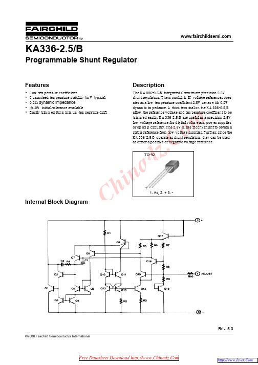
KA336_KA336B
Reverse Voltage (V)
w.China 1.27TYP ww [1.27 ±0.20]
1.27TYP [1.27 ±0.20]
14.47 ±0.40
ቤተ መጻሕፍቲ ባይዱ
0.38
+0.10 –0.05
3.60 ±0.20
3.86MAX
(0.25)
(R2.29)
+0.10 –0.05
KA336-2.5/B
m Figure 1. Reverse Voltage Change
Figure 2. Reverse Characteristics
www.Chinadz.Co Figure 3. Temperature Drift
Figure 4. Forward Characteristics
KA336-2.5/B
Programmable Shunt Regulator
Features
Description
• Low temperature coefficient
The KA336-2.5/B integrated Circuits are precision 2.5V
2. A critical component in any component of a life support device or system whose failure to perform can be reasonably expected to cause the failure of the life support device or system, or to affect its safety or effectiveness.
3362P 规格书
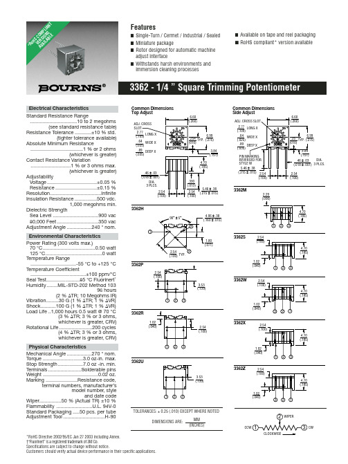
*RoHS Directive 2002/95/EC Jan 27 2003 including Annex.†“Fluorinert” is a registered trademark of 3M Co.Specifications are subject to change without notice.Customers should verify actual device performance in their specific applications.Electrical Characteristics Standard Resistance Range..................................10 to 2 megohms(see standard resistance table)Resistance Tolerance............±10 % std.(tighter tolerance available)Absolute Minimum Resistance......................................1 % or 2 ohms(whichever is greater)Contact Resistance Variation.............................1 % or 3 ohms max.(whichever is greater)AdjustabilityVoltage....................................±0.05 %Resistance..............................±0.15 %Resolution.....................................Infinite Insulation Resistance................500 vdc.1,000 megohms min.Dielectric StrengthSea Level .................................900 vac 80,000 Feet..............................350 vac Adjustment Angle..................240 °nom.Environmental Characteristics Power Rating (300 volts max.)70 °C......................................0.50 watt 125 °C.........................................0 watt Temperature Range.................................-55 °C to +125 °C Temperature Coefficient........................................±100 ppm/°C Seal Test........................85 °C Fluorinert †-STD-202 Method 10396 hours(2 % ∆TR; 10 Megohms IR)Vibration.........30 G (1 % ∆TR; 1 % ∆VR)Shock...........100 G (1 % ∆TR; 1 % ∆VR)Load Life ..1,000 hours 0.5 watt @ 70 °C(3 % ∆TR; 3 % or 3 ohms,whichever is greater, CRV)Rotational Life........................200 cycles(4 % ∆TR; 3 % or 3 ohms,whichever is greater, CRV)Physical CharacteristicsMechanical Angle..................270 °nom.Torque .............................3.0 oz-in. max.Stop Strength..................7.0 oz -in. min.Terminals........................Solderable pins Weight ........................................0.02 oz.Marking .......................Resistance code,terminal numbers, manufacturer’smodel number, styleand date codeWiper................50 % (Actual TR) ±10 %Flammability ..........................U.L. 94V-0Standard Packaging.....50 pcs. per tube Adjustment Tool..............................H-902.293362H3362M3362ZDIA.3362CLOCKWISEDIMENSIONS ARE:MM (INCHES)TOLERANCES: ±0.25 (.010) EXCEPT WHERE NOTED*Ro H S C O M P L I A N T V E R S I O N S A V A I L A B L ESpecifications are subject to change without notice.Customers should verify actual device performance in their specific applications.Resistance Resistance (Ohms)Code 1010020200505001001012002015005011,0001022,0002025,00050210,00010320,00020325,00025350,000503100,000104200,000204250,000254500,0005041,000,0001052,000,000205Standard Resistance TablePopular distribution resistance values listed in boldface. Special resistances available.REV. 04/06How to Order3362 P - 1 - 502 T __ LFModel StyleStandard or Modified Product Indicator-1 = Standard Product Resistance Code Optional Suffix LetterT =Knob*Packaging DesignatorBlank =Tube (Standard)R =Tape and Reel(M, U and P Pin Styles Only)A =Ammo Pack(M, U and P Pin Styles Only)TerminationsLF =100 % Tin-plated (RoHS compliant)Blank =90 % Tin / 10 % Lead-plated(Standard)*Knob option is available only in standard Tube packaging for terminal styles H, P , R and U.Consult factory for other available options.Packaging Specifications ALL PINS IN-LINE ON CENTERDIMENSIONS:1000/REEL/BOX2.54(.100) MM(INCHES) TOP ADJUST3362U-1, 3362P-1SIDE VIEW 3362U-1SIDE VIEW 3362P-1ALL PINS IN-LINE ON CENTERDIMENSIONS:750/REEL 1000/BOX2.54(.100) MM(INCHES) Meets EIA Specification 468.Top adjust models 3362H, P , R and U are available with a knob for finger adjustment.Add suffix letter “T” to order code.DIMENSIONS: MM/(INCHES)TOLERANCES: ±.25/(±.010) EXCEPT WHERE NOTEDProduct Dimensions。
BLC-120A规格书

型号:BLC-120规格书品名:直流无刷电机驱动器雨田电机有限公司YU TIAN MOTOR CO.,LTDBLC-120A该规格书适用于5A 的BLC-120A 直流无刷驱动器。
1 应用2 额定参数额定电压额定电流峰值电流额定转速DC12V ~30V5A8A适用电动机的最大转速20000RPM额定参数测量办法1 3362 3RVREF+DC-H A L L S E N S O RHW HV HU REF-M O T O R W V U DC+EN BRK F/R COM SV C O N T R O LRUN/ALMBLDC MOTOR DRIVERVDC: +12V ~ +30VPeak PowerP-sv TuneUnit:W12011010090807060504030BLC_120带动电动机自行运转。
连接或断开EN 端和COM 端的连接线可控制电动机的运行和停止。
当EN 端和COM 端连接时,电动机运行。
反之电动机停止运转。
4-2 方向控制连接或断开F/R 端和COM 端的连接线可实现电动机不同方向的运转。
当断开F/R 端和COM 端的连接线时,电动机顺时针运转。
当连接F/R 端和COM 端的连接线时,电动机逆时针运转。
当驱动器递交给客户的时,BRK 端和COM 端并未连接。
当接通电源时,驱动器BLD-120A 便能带动电动机自行运转。
连接或断开BRK 端和COM 端的连接线可控制电动机的自然运行和快速停止。
当断开BRK 端和COM 端的连接线时,电动机运转。
当连接BRK 端和COM 端的连接线时,电动机快速停止。
1 3362 34-3 快速停止4-4-2 通过外部电位器设定使用外部电位器进行调速时,电位器中间引出端连接SV 端,两侧的引出端分别连接REF+、COM 端。
此时的内置电位器(RV)需逆时针旋转至极限位置。
1 3362 33456789101112131514161712SV COM REF+4-4 调速方法4-4-1 通过内置电位器(RV)设定顺时针转动电位器(RV),电动机速度增大。
常用元件参数名称封装规格集总

1 W 1%色 环 金 属 膜 电 阻
2 W 1%色 环 金 属 膜 电 阻
3 W 1%色 环 金 属 膜 电 阻
自恢复保险丝瑞侃(Raychem)和泰科 贴 片 自 恢 复 保 险 丝
直 插 (DIP) 自恢复保险丝
贴 片 铝 电 解 电 容 系列:
(贴片.直插)二 三 极 管 系 列 :
S O T - 2 3 封 装
S O T - 8 9 封 装
T O - 3P 封 装
T O - 9 2 封 装
T O - 9 2 L 封 装
T O - 1 2 6 封 装
T O - 2 2 0 封 装
S O D - 1 2 3 (1206)
可 调 电 阻 3*3 (3 X 3)
可 调 电 容 3*4 (3 X 4)
可调电位器(精密电位器)系列:
3296W可调电位器
3266W可调电位器
3362P可调电位器
3386P可调电位器
3006P可调电位器
蓝白可调电位器(卧式)
功 率 电 感 器 系 列:
CD32 3.5*3.0*2.0mm
S O D - 3 2 3 (0805)
S O D - 5 2 3 (0603)
3 2 3 封 装
S O T - 3 6 3 封 装
S O D - 7 2 3 封 装
L L - 3 4 封 装
1/2W 0.5W (DO-35)稳 压
(SMD)贴 片 电 阻 系 列:
0201 5% (J) 1%(F) 电阻
0402 5% (J) 1%(F) 电阻
3362P503精密可调电阻

3 CW
3362 - 1/4 ” Square Trimming Potentiometer
Product Dimensions
The Model 3362P is available with a knob for finger adjustment. Add suffix letter “T” to order code.
Physical Characteristics
Mechanical Angle ..................270 ° nom. Torque .............................3.0 oz-in. max. Stop Strength ..................7.0 oz -in. min. Terminals ........................Solderable pins Weight ........................................0.02 oz. Marking .......................Resistance code,
-1 = Standard Product
Resistance Code
Optional Suffix Letter T = Knob*
Packaging Designator Blank = Tube (Standard) R = Tape and Reel (M, U and P Pin Styles Only) A = Ammo Pack (M, U and P Pin Styles Only)
Terminations LF = 100 % Tin-plated (RoHS compliant)
3362P精密可调电位器
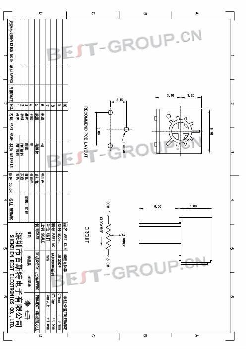
B.环境特性Environmental Characteristics
1.额定功率(最高工作电压300V) Rated Power(max. working voltage 300V) 2.工作温度范围Temperature Range 3.温度系数TCR 4.温度变化Temperature Variation 5.碰撞Collision 6.振动Vibration 7.气候顺序Climate Category +70℃ 0.5W,+125℃ 0W -55℃~ +125℃ ±200ppm/℃ △R≤±(2%R+0.1Ω),△(Uab/Uac)≤±2% 390m/s2,4000次 , △R≤±2%R 10~2000Hz,0.75mm,6h △R≤±1%R,△(Uab/Uac)≤±2% △R≤±3%R,R1≥100MΩ
3362p精密可调电位器精密电位器可调电位器精密导电塑料电位器多圈精密可调电阻精密可调电阻器可调电位器接法精密可调电阻电位器数字电位器电位器封装
产品规格书
PRODUCT SPECIFICATIONS
产品名称Product Name 精3362系列
料
号Part NO
6A1001004系列
A.电位器性能Electrical characteristics
1.阻值 Resistance 2.阻值偏差 Resistance Tolerance 3.阻值变化特性Resistance Taper 4.终端电阻Terminal Resistance □10Ω □20Ω □50Ω □100Ω □200Ω □500Ω □1KΩ □2KΩ □5KΩ □10KΩ□20KΩ □50KΩ □100KΩ□200KΩ □500KΩ□1MΩ □±10% □A □B □±20% □C □±30% □D □W □MN
