wisLink工业交换机说明书V
linksys交换机简要配置手册中文版(v1.1)

添加新管理员 system 点击 Add to ListUpdate 确认
第 8 页 共 13 页
设置完毕以后需要在下方工具条上选择保存配置
注意需要点击最下面的
北京能通万维网络科技有限公司内部文档
Save Settings Cancel Changes
修改 admin 密码,需要先创建一个用户例如 system 然后保存。
Interface Ingress Rate Limit Status
Port 20000
LAG
Egress Shaping Rate on Selected Port
Committed Information Rate(CIR)
50000
Committed Burst Size(CbS)
Update
Save settings 保持配置。
4. 把端口加入相应的vlan或trunk
设置端口作为 trunk 端口 点击 主菜单上的 VLAN Management 子选项 Port Setting 出现如下配置 默认情况下 端口都属于 access 接口,用户接入电脑用户,属于 vlan1 本例选择端口 1 作为 trunk 口作为 vlan 聚合端口以及上连链路
User Name:
admin
Password: Confirm Password:
(Alphanumeric)
第 3 页 共 13 页
北京能通万维网络科技有限公司内部文档
选项介绍 进入登录以后出现如下主界面 注界面为英文版,中文注解是本手册注解添加,实际使用中没有中文选项。
24-port 10/100 + 4-Port Gigabit Switch
SRW224G4
SIMATIC NET 工业以太网交换机 SCALANCE XC-200 操作说明说明书

SIMATIC NET工业以太网交换机SCALANCE XC-200操作说明02/2023法律资讯警告提示系统为了您的人身安全以及避免财产损失,必须注意本手册中的提示。
人身安全的提示用一个警告三角表示,仅与财产损失有关的提示不带警告三角。
警告提示根据危险等级由高到低如下表示。
危险表示如果不采取相应的小心措施,将会导致死亡或者严重的人身伤害。
警告表示如果不采取相应的小心措施,可能导致死亡或者严重的人身伤害。
小心表示如果不采取相应的小心措施,可能导致轻微的人身伤害。
注意表示如果不采取相应的小心措施,可能导致财产损失。
当出现多个危险等级的情况下,每次总是使用最高等级的警告提示。
如果在某个警告提示中带有警告可能导致人身伤害的警告三角,则可能在该警告提示中另外还附带有可能导致财产损失的警告。
合格的专业人员本文件所属的产品/系统只允许由符合各项工作要求的合格人员进行操作。
其操作必须遵照各自附带的文件说明,特别是其中的安全及警告提示。
由于具备相关培训及经验,合格人员可以察觉本产品/系统的风险,并避免可能的危险。
按规定使用 Siemens 产品请注意下列说明:警告Siemens 产品只允许用于目录和相关技术文件中规定的使用情况。
如果要使用其他公司的产品和组件,必须得到 Siemens 推荐和允许。
正确的运输、储存、组装、装配、安装、调试、操作和维护是产品安全、正常运行的前提。
必须保证允许的环境条件。
必须注意相关文件中的提示。
商标所有带有标记符号 ® 的都是 Siemens AG 的注册商标。
本印刷品中的其他符号可能是一些其他商标。
若第三方出于自身目的使用这些商标,将侵害其所有者的权利。
责任免除我们已对印刷品中所述内容与硬件和软件的一致性作过检查。
然而不排除存在偏差的可能性,因此我们不保证印刷品中所述内容与硬件和软件完全一致。
印刷品中的数据都按规定经过检测,必要的修正值包含在下一版本中。
Siemens AGDigital Industries Postfach 48 4890026 NÜRNBERG C79000-G8952-C442-14Ⓟ 02/2023 本公司保留更改的权利Copyright © Siemens AG 2016 - 2023.保留所有权利目录1简介 (7)2安全须知 (15)3安全建议 (17)4设备描述 (25)4.1产品总览 (25)4.2设备视图 (31)4.2.1SCALANCE XC206-2 (ST/BFOC) (31)4.2.2SCALANCE XC206-2 (SC) (32)4.2.3SCALANCE XC206-2G PoE (33)4.2.4SCALANCE XC206-2SFP (34)4.2.5SCALANCE XC208 (35)4.2.6SCALANCE XC208G PoE (36)4.2.7SCALANCE XC216 (37)4.2.8SCALANCE XC216-3G PoE (38)4.2.9SCALANCE XC216-4C (38)4.2.10SCALANCE XC224 (40)4.2.11SCALANCE XC224-4C (41)4.3附件 (41)4.4SELECT/SET 按钮 (47)4.5LED 指示灯 (49)4.5.1总览 (49)4.5.2“RM”LED (50)4.5.3“SB”LED (50)4.5.4“F”LED (50)4.5.5LED“DM1”和“DM2” (51)4.5.6LED“L1”和“L2” (51)4.5.7端口 LED (52)4.6C-PLUG (54)4.6.1C-PLUG 的功能 (54)4.6.2更换 C-PLUG (56)4.7组合端口 (57)4.8以太网供电 (PoE) (58)4.8.1符合标准的电源和电压范围 (58)4.8.2设备的 PoE 属性 (59)4.8.3电源传输和引脚分配 (30 W) (61)SCALANCE XC-200目录4.8.4电源传输和引脚分配 (60 W) (62)4.8.5组态 (62)5组装和拆卸 (63)5.1安装的安全注意事项 (63)5.2关于 SFP 收发器的一般说明 (66)5.3安装类型 (66)5.4在 DIN 导轨上安装 (67)5.4.1基于固定板的凹顶导轨安装 (67)5.4.2无固定板时的凹顶导轨安装 (69)5.5在标准 S7-300 导轨上安装 (70)5.5.1在带有固定板的标准导轨 S7-300 上安装 (70)5.5.2在不带固定板的标准导轨 S7-300 上安装 (71)5.6在标准导轨 S7-1500 上安装 (72)5.6.1在带有固定板的标准导轨 S7-1500 上安装 (72)5.6.2在不带固定板的标准导轨 S7-1500 上安装 (74)5.7基于固定板的墙式安装 (75)5.8更改固定销的位置 (76)5.9拆卸 (77)6连接 (79)6.1不使用 PoE 的设备的安全注意事项 (79)6.2PoE 设备的安全注意事项 (80)6.3有关在危险场所使用的安全注意事项 (82)6.4附加说明 (85)6.5接线规则 (86)6.624 V DC 电源 (87)6.754 V DC 电源 (88)6.8信号触点 (90)6.9功能性接地 (91)6.10串口 (92)6.11工业以太网 (94)6.11.1电气 (94)6.11.2光纤 (95)SCALANCE XC-200目录7维护和清洁 (97)8故障排除 (99)8.1使用 TFTP 下载新固件(无需 WBM 和 CLI) (99)8.2恢复出厂设置 (100)9技术规范 (101)9.1SCALANCE XC206-2 (ST/BFOC) 的技术规范 (101)9.2SCALANCE XC206-2 (SC) 的技术规范 (104)9.3SCALANCE XC206-2G PoE 的技术规范 (107)9.4SCALANCE XC206-2G PoE (54 V) 的技术规范 (110)9.5SCALANCE XC206-2G PoE EEC (54 V) 的技术规范 (113)9.6SCALANCE XC206-2SFP 的技术规范 (116)9.7SCALANCE XC206-2SFP G 的技术规范 (119)9.8SCALANCE XC206-2SFP EEC 的技术规范 (122)9.9SCALANCE XC206-2SFP G EEC 的技术规范 (125)9.10SCALANCE XC208 的技术规范 (128)9.11SCALANCE XC208G 的技术规范 (130)9.12SCALANCE XC208G PoE 的技术规范 (132)9.13SCALANCE XC208G PoE (54 V) 的技术规范 (134)9.14SCALANCE XC208EEC 的技术规范 (136)9.15SCALANCE XC208G EEC 的技术规范 (138)9.16SCALANCE XC216 的技术规范 (140)9.17SCALANCE XC216EEC 的技术规范 (142)9.18SCALANCE XC216-3G PoE 的技术规范 (144)9.19SCALANCE XC216-3G PoE (54 V) 的技术规范 (146)9.20SCALANCE XC216-4C 的技术规范 (150)9.21SCALANCE XC216-4C G 的技术规范 (153)9.22SCALANCE XC216-4C G EEC 的技术规范 (156)9.23SCALANCE XC224 的技术规范 (159)9.24SCALANCE XC224-4C G 的技术规范 (161)9.25SCALANCE XC224-4C G EEC 的技术规范 (164)9.26机械稳定性(运行时) (167)SCALANCE XC-200目录9.27射频辐射符合 NAMUR NE21 标准 (167)9.28电缆长度 (167)9.29交换特性 (168)10尺寸图 (171)11证书和认证 (179)索引 (189)SCALANCE XC-200简介1操作说明的用途这些操作说明适用于 SCALANCE XC-200 系列产品的安装和连接。
【推荐】国威交换机说明书-优秀word范文 (18页)

本文部分内容来自网络整理,本司不为其真实性负责,如有异议或侵权请及时联系,本司将立即删除!== 本文为word格式,下载后可方便编辑和修改! ==国威交换机说明书篇一:国威WS848-P型电话交换器说明书目录一、系统简介 .................................................................. ..................................................................... .....1.1概况 .................................................................. ....1.2主要功能 ..................................................................二、产品规格 .................................................................. ..................................................................... .....三、结构和安装 .................................................................. ......................................................................3.1外观说明 ..................................................................3.2安装环境 ..................................................................3.3接地方法 ..................................................................四、一般功能编程举例??????????????????????????????4.1 怎能样开通或关闭外线?????????????????????????4.2怎样录制电脑话务员的语音?????????????????????????4.3怎样开通电脑话务员?????????????????????????4.4怎样设置外线打进指定分机响铃???????????????????????4.5怎样设置分机打出直拨外线或拨9打外线???????????????????4.6怎样设置外线打出专线专用?????????????????????????4.7怎样设置长途自动加发IP?????????????????????????4.8怎样设置自编分机号?????????????????????????五、系统编程 .................................................................. ..................................................................... .....5.2如何进入编程状态5.2系统初始化 ................................................................5.3外线开通与关闭设置 ........................................................5.4外线打入响应方式选择 ......................................................5.5 外线打入指定分机响铃设置 ..................................................5.6分机打出方式设置 ..........................................................5.7 分机外线打出权限设置 ......................................................5.8 分机允许使用外线权限设置 ..................................................5.9分机国内长途、声讯台及限制电话权限设置 .....................................5.10分机国际长途电话权限设置 .................................................5.11分机外线通话时间设置 .....................................................5.12分机IP功能设置 ..........................................................5.13分机号码更改设置 .........................................................5.14 系统密码更改设置 .........................................................5.15 限制码设置 ...............................................................5.16 IP号码设置 .............................................................5.17 电脑话务员接通时间 ......................................................六、系统编程表 .................................................................. ......................................................................七、功能使用表 .................................................................. ......................................................................八、功能使用具体操作方法 .................................................................. ..................................................8.1呼叫内线分机 ..............................................................8.2外线打出 ..................................................................8.3指定外线打出 ..............................................................8.4外线打入响应 ..............................................................8.5日夜方式选择 ..............................................................8.6外线电话转接 ..............................................................8.7 外线保留及取回 ............................................................8.8遇忙转移及无人接转移 ......................................................8.9代接电话 ..................................................................8.10电脑话务员录制 ...........................................................一、系统简介1.1概况本集团电话是在综合国内外众多集团电话优点的基础上开发出来的新一代通信设备,并按照中华人民共和国信息产业部技术要求生产。
威而信程控用户交换机说明书

第二章系统编程2.0 注意事项2.0.1 必须在801分机上进行功能设置:2.0.2 本章所有操作均属高等级指令,非集团电话最高使用权限者(无系统密码者)将无法操作;2.0.3 本章所有操作均需在开锁(输入正确系统密码)后且未挂机前才有效,每次挂机系统自动上锁;2.0.4 按“*”键进入设置,按“#”键结束设置,在编程过程中发现输错可直接用“*”键重新开始,不必挂机;2.0.5 若总机己设为直拨外线状态时,用户必须先按一个”*”键进入内线,然后再按“*”开始设置;2.0.6 设置结束时,听到"-嘟-"一声表示设置正确,若为"-嘟-嘟-嘟-"则表示设置有误,请查明再设;2.0.7 属控制多用户的指令都有批处理操作方式,使用批处理操作可提高设置速度和准确性。
2.1 系统设置开锁格式: *01 ABCD#注释: “ABCD”为系统密码例如: 想修改系统设置,则在设置前,必须先开锁方能进行(假如系统密码为”1234”) 提801分机——输入“* 0 1 1 2 3 4 # ”——“嘟”一声——继续其它设置注意:系统将在“801”挂机时自动上锁,故“801”在开锁后不能挂断,在听到“嘟”一声后便可进行设置。
若遇挂机,则在设置前必须再次开锁。
2.2 更改系统密码格式: *02 ABCD#注释: “ABCD”为新密码例如: 若想将系统密码更改为”0000”,则提801分机开锁——输入“* 0 2 0 0 0 0 # ”——“嘟”一声——挂801分机注意:〈1〉.本集团电话系统原始密码为”1234”;〈2〉.在使用系统前,建议先更改密码;〈3〉.若密码遗忘,可在找到机器“出厂编号”后与本公司售后服务部联系。
〈4〉.以下各操作举例均为己开系统锁的设置步骤。
2.3 设置开通外线格式: * 3 a b c d e f #注释: a、b、c、d、e、f为欲开通的外线口号例如:某公司有四条外线,则可将外线接入一到四号外线口,且将系统设置为四条外线状态:提801分机开锁——输入“* 3 1234 # ”——“嘟”一声——挂801分机在使用中,有时有特殊需要,用户无需将外线顺序接入一至四号口,而可按需要接入,如接入二、四、五和第六口,则提801分机开锁——输入“ * 3 2456 # ”——“嘟”一声——挂801分机若用户没有外线而将集团电话作为内部交换机,可将系统设为无外线状态:提801分机开锁——输入“ * 3 # ”——“嘟”一声——挂801分机2.4 中继分组2.4.1 设置某外线为某几部分机的专线格式: * 4 1 A abc #注释: “A”为外线口号;”abc”为分机现时号例如: 将第三号外线设为”803”和”335”(335为某分机的现时号)的专线,设置如下: 提801分机开锁——输入“* 4 1 3 803 # ”——“嘟”一声后挂机——再提机开锁输入“ * 4 1 3 335# ”——“嘟”一声——挂801分机或用批处理方式:提801分机开锁——输入“* 4 1 3 803 # ”——“嘟”一声——继续输入“3 335 #”——“嘟”一声——挂801分机注意:(1)每根外线最多设置四部分机为其专线;(2)取消专线只需重新开通外线(见2.3项)即可。
英特威尔交换机快速入门指南说明书

Getting Started Guide December, 2017Tabl e o f ContentsP urpose (3)Before you start (3)1 L ogin to the switch v ia console port (4)Bring up networ k operating s y ste m I N OS (4)235 4 6 E nter pri v ileged m ode and execute C L I co mm ands (5)L ogin to the switch v ia m anage m ent port - ssh (6)E nter con f iguration m ode (9)Assign static I P address to m anage m ent port (10)Bare m etal switch pre-installed with O N I E (12)78Login to I N OS (5)PurposeThis getting started guide provides steps necessary (as shown below) to initially bring up the Inventec switches for configuration.1.Login to the switch via console port “CON”2.Bring up Inventec Network Operating System “INOS”3.Login to “INOS”4.Enter privileged mode and execute CLI command to show management IP address5.Login to the switch via management port “MGMT”6.Enter configuration mode and perform an simple configuration as an example to show how itworks7.Assign static IP address to the management port8.Bare metal switch preinstalled with ONIEFor additional installation and configuration information for the Inventec switches, see the Inventec switch documentations: INOS Administration Guide and INOS CLI Command Reference.Before you startRefer to the switch User Manual “Appendix A” to make sure the switch is properly positioned o n desktop or rack mounted. DHCP is enabled by default to acquire IP address on the network. To g et access to the IP address information by console, configure the terminal server or terminal-emulation program to use the following settings:Baud rate: 115200 bpsData bits: 8Parity: noneStop bit: 1Flow control: nonePlease note: This getting started guide shows how to access the switch by console, then by management port using IP address acquired by DHCP.To configure static IP address on management port to access the switch. Please refer to Step 7. “Assign static IP address to the management port.”Now connect a console cable from terminal server to the console port “CON” at the back of the switch.1.Login to the switch via console port “CON”To login to the switch. Please note, the first stop is the “Inventec Linux”. In which INOS is running as an application in the background. Use admin/inventec for login and password as shown below to login to Inventec Linux.2.Bring up Network Operating System INOSNext we need to bring up INOS. In order to do so, the root access is required. On command p rompt, type “sudo –s” and insert the default password “inventec” to change user login from “admin” to “root”. The command prompt will be changed from “admin@localhost” to “root@localhost”.Type “inos-console” to bring up INOS to exit current login and a new user login prompt will show up.3.Login to INOSTo login to INOS, type “admin” for User. Please note, there is no password for this. Press “Enter” key to bypass password query. When “(localhost)>” prompt is shown, system is ready for use.4.Enter privileged mode and execute CLI command to show management IP addressIn order to execute CLI command, command prompt needs to be on privileged mode.Type “enable” to enter privileged mode. The command prompt sign should change from “>” to “#”.Let’s try some basic CLI commands:Type “show version” to show basic information of the system.Type “show serviceport” to show management IP address. Record the IP address. You will be using the IP address to login to the switch.5.Login to the switch via management port “MGMT”Connect an Ethernet cable from management port “MGMT” at the back of the switch to network. Launch a terminal emulator program such as “PuTTY”. Use “SSH” to connect to the management IP address with port 22, as shown below. Select “Open” to continue.First time login it will show the warning that “the server’s host key is not cached in the registry. ……”. Press “YES” to continue.On login prompt, enter “admin” and “inventec” for user and password to login to “inventec Linux” as the same shown previously.Type “sudo –s” and enter password “inventec” to change user from “admin” to “root”.Type “inos-cli” to bring up INOS. Please note, this command is not the same as the one (“inos-console”) used in the console login shown previously.Next it will show “Initializing console session. Press ^Z to exit”. Press “Enter” key to continue.6.Enter configuration mode and perform a simple configuration as an example to show how it works Now you can change the command prompt from “localhost” to any name by typing “hostname <new name>”. For example, below shows how to change command prompt name from “localhost” t o “host123”.Next let’s do a basic configuration to turn on a port. Type the configuration b elow. Note the “config” command opens an editor to allow configuration. The “end” command exits the configuration mode. Below example shows how to enable port 1 of the switch.l oca l host:~#l oca l host :~# inos-cliconsole session. Press ^z to exit.l oca l host) #l oca l host) >l oca l host) >enl oca l host) #hostname host123#To verify the configuration. Type the show command as shown below. The output shows port 1 is configured to be enabled.7.Assign static IP address to the management portTo configure static IP address on management port to access the switch built with embedded platform, please refer to INOS Administration Guide, Section 2: Getting Started with Switch Configuration/“Configuring Service Port Information”. If you do not see the serviceport IP configuration commands, chances are you are working with a switch that’s built with x86 base platform, so p lease move on to the below paragraph.To configure static IP address on management port to access the switch built with x86 based platform, please use the following steps to configure static IP address for eth0 port in Linux environment: Steps to make the ip address of a system as static1.Make backup copy of the interface file (cp interfaces interfaces.bak)2.Open interface file (sudo vi /etc/network/interfaces) configureinterface 0/1no shutdownendshow running-config interface 0/13.Look forauto eth0 & iface eth0 inet dhcp4.Replace the above commands withauto eth0iface eth0 inet staticaddress 192.168.1.100(Enter desired ip here)netmask 255.255.255.0network 192.168.1.0broadcast 192.168.1.255gateway 192.168.1.15.Then exit the editor (press ESC and “:”, type “x”), and enter belowsudo ifdown eth0; sudo ifup eth08.Bare metal switch preinstalled with ONIEFor systems shipped as bare metal switches, Inventec provides the ONIE installerthrough which the supported vendor’s NOS can be installed. The followingexample shows the steps to install Pica’s OS image from the ONIE prompt using anexternal USB.1.First, copy the image to the USB formatted with FAT32, then plug the USB to the switch.2.Apply the below steps from ONIE prompt to mount the USB and install the image:3.mkdir /diagmount /dev/sdb1 /diagcd /diag4.ls –l verify the image is there.5.onie-nos-install <Image>rootmkdir /diagmount /dev/sdb1 /diagcd /diagls -lonie-nos-install picos-2.7.1.binAfter installation the switch boots up with PicOS v2.7.1admin pica8version。
4 口千兆环网工业交换机 用户手册说明书

4口千兆环网工业交换机用户手册版本:V2.01发布日期:10/2021大连德嘉工控设备有限公司目录1.产品概述 (3)2.产品特性 (3)3.产品外观 (4)4.安装指南 (5)5.网络拓扑结构 (5)近些年来,随着网络技术的飞速发展,以太网进入了工业自动化领域,形成了新型的工业以太网控制网络技术。
这是由于工业自动化系统向分布化、智能化控制方面发展,开放的、透明的通讯协议以及使用的简洁性已得到工控业界的广泛认可,致使越来越多的工控设备支持工业以太网通信。
以太网技术引入工业控制领域,其技术优势非常明显:(1)Ethernet是全开放网络,遵照网络协议不同厂商的设备可以很容易实现互联。
(2)以太网能实现工业控制网络与企业信息网络的无缝连接。
(3)软硬件成本低廉,以太网技术现已非常成熟,支持以太网的软硬件受到厂商的高度重视和广泛支持,有多种软件开发环境和硬件设备供用户选择。
(4)通信速率高,当前以太网的通信速率为10M、100M、1000M开始广泛应用4口千兆环网交换机具有4个1000M/100M/10M自适应以太网交换机接口,使用灵活方便,可组成总线型和星型以及冗余环网等各种较复杂的网络拓扑结构。
采用工业级标准设计,-10~+70℃宽温型工业级工作温度。
可广泛的用于PLC、HMI、DCS、工控机等各种基于工业以太网的工控设备,支持多种工业以太网协议,如PROFINET(IRT除外)、MODBUS TCP/IP、TCP/IP等。
整体设计采用“凹陷”网口设计,外观上和普通交换机大有差别,将网线水晶头能够有力的支撑保护住。
这样使用类似西门子网线金属头时,可将其前半部分掩盖住,不至于全都裸露在外面,可以能够有效地“拖住”网线,使网线水晶头也不会容易脱落,而且看起来还非常美观。
2产品特性●电源电压:标准工业24V直流电压供电。
●符合IEEE802.3x、10/100/1000Base-T、IEEE1000Base-X/IEEE100Base-FX工业以太网标准。
工业以太网交换机配置手册

管理型工业以太网交换机用户配置手册
工业以太网交换机 用户配置手册
管理型工业以太网交换机用户配置手册
手册约定
图形界面格式约定
格式 <>
意义 尖括号中的文字表示为按钮名,如单击<修改>按钮
【】
引号中的文字表示为窗口名、菜单名,如打开【快速上网向导】页面
--
简单的操作步骤连接符,如依次打Fra bibliotek[开始]--[控制面板]--[网络连接]
2.1 配置串口连接 ......................................................................................................... 12 2.2 用户名和密码 ......................................................................................................... 12 2.3 串口配置命令 ......................................................................................................... 13
SIWR-MS100-4G 三卡工业无线路由器使用说明书
SIWR-MS100-4G三卡工业无线路由器产品说明书Rev. 2.02020/08SIWR-MS100-4G三卡工业无线路由器使用说明书注意事项! 请勿带电插拔核心板及外围模块!! 请遵循所有标注在产品上的警示和指引信息。
! 请保持本产品干燥。
如果不慎被任何液体泼溅或浸润,请立刻断电并充分晾。
! 使用中注意本产品的通风散热,避免温度过高造成元器件损坏。
! 请勿在多尘、脏乱的环境中使用或存放本产品。
! 请勿将本产品应用在冷热交替环境中,避免结露损坏元器件。
! 请勿粗暴对待本产品,跌落、敲打或剧烈晃动都可能损坏线路及元器件。
! 请勿使用有机溶剂或腐蚀性液体清洗本产品。
! 请勿自行修理、拆卸本公司产品,如产品出现故障请及时联系本公司进行维修。
! 擅自修改或使用未经授权的配件可能损坏本产品,由此造成的损坏将不予以保修。
联系方式如产品使用过程中出现硬件故障可根据以下联系方式进行沟通:邮件:******************网址:地址:深圳市宝安区新安街道留仙大道2号汇聚创新园2栋2306SIWR-MS100-4G三卡工业无线路由器使用说明书目 录一、产品概述 (1)二、硬件接口说明 (2)三、产品操作说明 (2)3.1配置路由器 (4)SIWR-MS100-4G三卡工业无线路由器使用说明书一、产品概述SIWR-MS100-4G是一款多功能路由器设备,具有强大的异构网络通讯能力,支持百兆RJ45以太网和IEEE 802.11b/g/n标准多种连网方式,为客户提供便捷的有线和无线宽带接入方案。
本产品采用DC 9∽36V宽电压设计,更好的适应复杂的工业供电,并具备防雷击、防浪涌的供电保护设计。
本产品采用高性能网络处理器,基于高可靠Linux嵌入式操作系统开发,提供友好的可视化管理界面和安全的VPN接入功能,实现安全、稳定、高速的移动宽带接入。
本产品可广泛应用于工业自动化、智慧城市、仓储、物流、分拣、电力、大型机械设备、以及各类信息化/工业化改造。
Linksys SR2024 24-Port Gigabit 交换机用户说明书
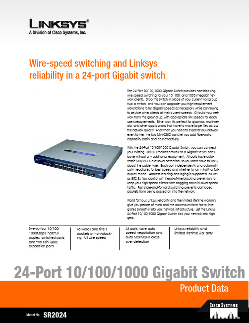
Wire-speed switching and Linksys reliability in a 24-port Gigabit switchTwenty-four 10/100/1000Mbps, half/full duplex, switched ports, and two Mini-GBIC expansion portsLinksys reliability and limited lifetime warrantyForwards and filters packets at non-block-ing, full wire speedAll ports have autospeed negotiation and auto MDI/MDI-X cross-over detectionThe 24-Port 10/100/1000 Gigabit Switch provides non-blocking, wire speed switching for your 10, 100, and 1000 megabit net-work clients. Drop this switch in place of your current workgroup hub or switch, and you can upgrade your high-requirement workstations to full Gigabit speeds as necessary, while continuing to service other clients at their current speeds. Or build your net-work from the ground up, with appropriate link speeds for each user's requirements. Either way, it's perfect for graphics, multime-dia, and other applications that have to move large files across the network quickly. And when you need to expand your network even further, the two Mini-GBIC ports let you add fiber-optic capability easily and cost effectively.With the 24-Port 10/100/1000 Gigabit Switch, you can connect your existing 10/100 Ethernet network to a Gigabit server back-bone without any additional equipment. All ports have auto-matic MDI/MDI-X crossover detection, so you don't have to worry about the cable type. Each port independently and automati-cally negotiates for best speed and whether to run in half- or full-duplex mode. Address learning and aging is supported, as well as 802.3x flow control with head-of-line blocking prevention to keep your high-speed clients from bogging down in lower-speed traffic. Fast store-and-forward switching prevents damaged packets from being passed on into the network.World famous Linksys reliability and the limited lifetime warranty give you peace of mind and the rackmount form factor inte-grates smoothly into your network infrastructure. Let the Linksys 24-Port 10/100/1000 Gigabit Switch kick your network into high gear.Features•24 RJ-45 ports for 10BASE-T/ 100BASE-TX/1000BASE-TX con-nections•Supports half duplex and full duplex modes auto-negotia-tion for all ports.•Auto MDI/MDI-X support on all ports for easy cable detec-tion•Efficient MAC Address learn-ing engine supports up to 8K MAC Addresses •Provides store-and-forward forwarding scheme.•Standard width and mounting kit (included) make it easy to be installed into a rack •Two mini-GBIC ports for easy expansion to other mini-GBIC equipped switchesLinksysA Division of Cisco Systems, Inc.18582 Teller AvenueIrvine, CA 92612 USAE-mail:************************************Web:Linksys products are available in more than 50 countries, supported by 12 Linksys Regional Offices throughout the world. For a complete list of local Linksys Sales and Technical Support contacts, visit our Worldwide Web Site at .Package Contents•One 24-Port 10/100/1000 Gigabit Switch •One AC Power Cord•One User Guide with Registration Card •One Set of Rack Mounting brackets24-Port 10/100/1000 Gigabit SwitchSpecificationsModel Number SR2024Standards IEEE 802.3, 802.3u, 802.3x, 802.3abPorts24 RJ-45 10/100/1000 + 2 Mini-GBIC portsCabling Type Category 5e or betterLEDs System, 1 through 24EnvironmentalDimensions432 mm x 45 mm x 349 mm(W x D x H)(17.01" x 1.75" x 13.74")Unit Weight7.98 lb. (3.62 kg)Power Input110-120VAC, 100WCertifications FCC Class B, CEOperating Temp.32ºF to 122ºF (0ºC to 50ºC)Storage Temp.-40ºF to 158ºF (-40ºC to 70ºC)Operating Humidity20% to 95%, Non-CondensingStorage Humidity5% to 95%, Non-CondensingSpecifications are subject to change without notice. Linksys and EtherFast are registered trademarks of Cisco Systems, Inc. Other brands and product names are trademarks or registered trademarks of their respective holders. Copyright © 2003 Cisco Systems, Inc. All rights reserved.SR2024-DS-80508A-KO。
SIEMENS 工业以太网交换机 说明书

SCALANCE — 性能可延展西门子全集成自动化理念已在全球各地成功演绎了无数次;通过共享工具和标准化机制,可实现集成解决方案。
最重要的基础工作之一就是致力于SIMATIC NET 工业通讯的发展。
SCALANCE 即是里程碑式成果,一种全新的有源网络部件,用于构建集成网络。
2SCALANCE XXWS安全性工业无线局域网工业以太网交换机SCALANCE S保证工业安全利用安全机制,如认证、数据加密或访问控制,SCALANCE S 可以保护网络和数据不受侵袭活动,操控和未经授权访问。
SOFTNET 安全客户机用于SCALANCE 保护下设备的安全访问。
SCALANCE W用于工业无线局域网的可靠无线电技术基于工业无线电局域网,SCALANCE W 将集成通讯拓展到一个过去很难甚至不可能进入的领域。
SCALANCE W 是通过专用的数据传输速率或监控无线连接做到这点。
SCALANCE W 采用了IEEE 802.11a / b / g / h / e / i无线局域网国际标准。
SCALANCE X从入门级到高性能网络工业以太网交换机SCALANCE X 提供一系列的不同功能的工业以太网交换机,例如:通过PROFINET 、SNMP 或是Internet诊断,以满足对网络结构、数据传输速率和端口数的不同需要。
这些有源网络部件可完美相互协同,旨在严酷的工业环境下能够集成、灵活、安全、高性能的构建网络。
工业环境下的通讯工业通讯与办公环境下的通讯有着根本上的不同。
在办公环境下,很多用户连接一台服务器;客户之间并没有交叉连接。
而这种数据传输在建立通讯连接时,多个用户同时连接服务器时会导致阻塞和延时。
这不能用于自动控制,因为循环的执行进程处理需要输入更新的数据来对组件发出适应的控制指令。
此外,应用技术,通讯关系和网络结构也必须各自能够适应严酷的工业环境。
工业网络必须能够反应灵活并在短时间内满足市场需求,重组必须快速而高效。
工业网络用户使用手册(赫思曼)
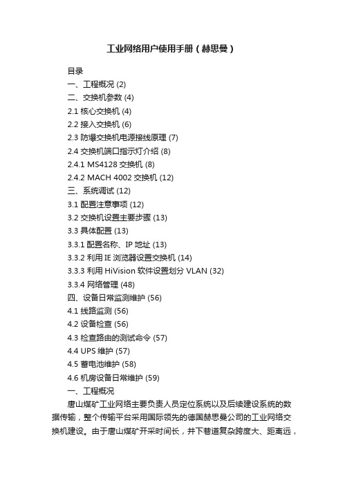
工业网络用户使用手册(赫思曼)目录一、工程概况 (2)二、交换机参数 (4)2.1 核心交换机 (4)2.2 接入交换机 (6)2.3 防爆交换机电源接线原理 (7)2.4 交换机端口指示灯介绍 (8)2.4.1 MS4128交换机 (8)2.4.2 MACH 4002交换机 (12)三、系统调试 (12)3.1 配置注意事项 (12)3.2 交换机设置主要步骤 (13)3.3 具体配置 (13)3.3.1配置名称、IP地址 (13)3.3.2 利用IE浏览器设置交换机 (14)3.3.3 利用HiVision软件设置划分VLAN (32)3.3.4 网络管理 (48)四、设备日常监测维护 (56)4.1 线路监测 (56)4.2 设备检查 (56)4.3 检查路由的测试命令 (57)4.4 UPS维护 (57)4.5 蓄电池维护 (58)4.6 机房设备日常维护 (59)一、工程概况唐山煤矿工业网络主要负责人员定位系统以及后续建设系统的数据传输,整个传输平台采用国际领先的德国赫思曼公司的工业网络交换机建设。
由于唐山煤矿开采时间长,井下巷道复杂跨度大、距离远,分A、B两区。
在网络设计时,井下设计20台防爆MS4128接入交换机,结合实际情况暂安装16台,其它留作后期网络扩展。
具体安装位置如下:A区:902泵房、11水平泵房、12水平泵房;B区:502配电室、8号井车房配电室、5021变电硐、7070机头配电室、702配电室、8070机头配电室、905泵房、8050配电室、南三泵房配电室、岳胥区变电硐、12号井变电硐、十一横管变电硐、八横贯配电室。
结合实际情况,将井下网络分为3个千兆光纤环形网络,A区1个千兆环、B区两个千兆环,通过地面机房的两台核心交换机实现互连、互通。
具体环网结构拓扑如下图:唐山煤矿工业网络拓扑图二、交换机参数德国赫思曼工业以太网交换机在煤矿自动化系统中的应用最广泛、也是是目前全球工业以太网技术的领导者。
wisLink工业交换机说明书V

目录
第一章 wisLink W-100 工业交换机技术说明书 第二章 wisLink W-1600 工业交换机技术说明书 第三章 wisLink W-1601 工业交换机技术说明书 第四章 wisLink W-1700 工业交换机技术说明书 第五章 wisLink W-802 工业环网交换机技术说明书 第六章 wisLink W-802M 工业环网交换机技术说明书 第七章 wisLink W-802G 工业交换机技术说明书 第八章 wisLink w-200 光电转换器技术和使用说明书 第九章 wisLink W-2000 工业以太网交换机技术说明书 第十章 wisLink W-2400 工业交换机技术说明书
2. 装置技术参数
交换技术:
符合标准
IEEE802.3 10BASE-T IEEE802.3u 100BASE-TX/100BASE-FX IEEE802.3x Flow Control and Back pressure IEEE802.3ad Port trunk with LACP IEEE802.1p Class of service IEEE802.1q VLAN
抗干扰性能 绝缘耐压标准
10M-14880 pps、100M-148800pps、1000M-1488000pps 4.8Gbps 存储转发 全双工 IEEE802.3x,半双工背压式 8 K、自动学习 < 5ms
第 3 页 共3页
wisLink W-1600 工业交换机 技术说明书
版本:V1.1
江苏金智科技股份有限公司
wisLink W-1600 工业交换机技术说明书(V1.1)
目录
1. 概述 ................................................................................................................................................................... 1 2. 装置技术参数.................................................................................................................................................... 1 3. 装置尺寸图........................................................................................................................................................ 2 4. 装置的机械安装和接线.................................................................................................................................... 3
Industrial_HiVision_Quick_Start_Guide_v1

Industrial HiVisionQuick Start Guidev1.0 August 2011ContentsINTRODUCTION (3)INSTALLATION (4)GETTING STARTED (13)NETWORK HIERARCHY (17)DEVICE DISCOVERY (28)TOPOLOGY DISCOVERY (39)STATUS DISPLAY (48)RUN MODE (54)CONCLUSION (56)INDUSTRIAL HIVISION EVALUATION GUIDE (57)IntroductionA Quick Start Guide with 57 pages may seem like a contradiction in terms. But most of the space in this document is taken up with screen shots.By comparing the screen shots in this document with the screens on your PC, you can be certain that you are on the right track to success.Three pages of densely packed text will not provide you with a valuable learning experience. In this case, a picture really is worth a thousand words.There is no Network Management system which works out of the box. Some configuration is always required.Industrial HiVision is a network configuration and supervision application designed from the ground up for use in industrial networking environments. It offers the innovative functionality which is required in this space, but does not require a lifetime of IT experience to get it running.This document will take you step by step through the basic configuration. By following these instructions you will get extensive knowledge about your network topology, and in-depth visibility into the day to day operation of your network.Of course, as a network administrator you will need more than this. And Industrial HiVision can provide it.But the instructions provided in this document will result in a solid foundation upon which you can build your comprehensive network configuration and management solution, based on Industrial HiVision..InstallationTo begin the installation, double click on the .exe setup file.The installation files will be extracted, and then the setup will begin.Select a language. The options are English and German. This selection is the language for the installation routine only. Once Industrial HiVision is installed, you will have a choice of six languages.If your PC operating system is in German, then German will be the default language. Otherwise the default language will be English.Click the “Next” button. You must then agree to the licensing terms.Select the folder in which to install Industrial HiVision.You will then have the option to install four different components.Server Installation – this installs the Industrial HiVision server, as well as the service and the database. The server must be installed on one PC in the network.Client Installation – this installs the Graphical User Interface. The GUI can be installed on the same PC as the Server, or on another PC. The GUI does not require a license, and can be installed on as many PCs as required.OPC Service – Industrial HiVision can convert SNMP variables and other parameters to OPC Tags. If you want to pass information about your network to a SCADA system using OPC, then install this option. If not, the option is not required.ActiveX Control – the Industrial HiVision GUI is available as an ActiveX control. This allows it to be embedded directly into a SCADA system. If this is not a requirement, then do not select this option.If your operating system supports it, you will see an option to install SMScom. This program is used to send SMS message from within Industrial HiVision.The installation will then begin.The Industrial HiVision service is required to monitor the network. If this installation will be monitoring the network permanently, select “Start services automatically…”. If Industrial HiVision will only be running periodically, select “Start services manually” to conserve system resources. In either case, the Service will be installed.Getting StartedStart Industrial HiVision by double clicking the icon on your PC desktop.Alternatively the program can be started from:Start -> Programs -> Hirschmann -> Industrial HiVision.The splash screen will appear.If the Industrial HiVision service is not running, because you selected the “Start services manually” option during installation or because you have stopped the service, you will be prompted to start the service.The service must be running in order for Industrial HiVision to supervise the network. If you select the “No” option, Industrial HiVision will not start. Select the “Cancel” option if you want to connect to an Industrial HiVision server on a different PC.The GUI will then connect to the Service and load the remaining components.The Industrial HiVision GUI consists of three main areas.The large central window contains your network topology maps, as well as lists of information about your devices, the ports on the devices, the connection between devices, and many other device parameters.The window on the left contains your network hierarchy. It works in the same way as Windows Explore. This allows you to create multiple levels of network maps, representing ever increasing detail about your network topology, in a well structured manner.The window at the bottom of the screen is the Event Log. This is where you will find messages about the status of your network, and actions performed by Industrial HiVision.If you would prefer to have the GUI in a different language, click the “Preferences” button at the top right of the screen. The Preferences window will open. Select “Appearance” from the left hand menu. Then select your preferred language.Network HierarchyYour first task is to design the hierarchy layout of your network. This will be a logical representation of the network layout.There is no limit to the number of sub-folder levels which can be created.The “New Devices” folder is used to store newly discovered devices, if no other default folder has been specified.The “Unused Devices” folder is used to store devices that you do not want to supervise, but you also do not want to delete.Start building your network hierarchy from the “My Network” folder.To rename the “My Network” folder, right click on it and select the “Properties” menu.In the “Name” field, enter the name of your network. Leave the other parameters in their default setting.To create sub-folders within the “Factory Network” (formerly “My Network”) folder, click the folder icon. In the topology window, right click on any white space.New -> FolderYou will now have a new folder called “New Folder”. The “Factory Network” folder now has a “+” symbol next to it, indicating that it contains subfolders.To give the new folder a meaningful name, right click it and select the “Properties…” menu item.Type the new name into the “name” field, and click the “OK” button.Create additional sub-folders and sub-sub-folders, and so on, until you have completed the logical layout of your network topology.By default the icon used for folders represents a folder. However this can be easily changed, to better clarify the contents of the folder. Some examples include: •An icon of a building, to represent the network inside the building.•An icon of a ring, to represent a network ring.•An icon of a network device, which when clicked will open a new map showing the connected end devices.To change the icon used by a folder, right click the folder and select the “Properties” menu item.Click the “Realistic” icon button.Select an icon from one of the built-in icon folders. There are many to choose from. Or use your own icon. The icons are 64 bit by 64 bit .png images, with a transparent background.An icon preview is available. Click the icon file once to see the icon in the right hand pane.Device DiscoveryNow you have created a structured hierarchy, which will be easily understood by your network operators. The next step is to populate the structure with network devices and end devices.Industrial HiVision offers two methods to discover network devices.The first is HiDiscovery. This is a mechanism proprietary to Hirschmann, and which therefore only works with Hirschmann network devices. HiDiscovery will enable you to find network devices on a single Ethernet network, even if those devices do not have IP addresses. HiDiscovery will also allow you to give IP addresses to Hirschmann devices.The second method is to scan IP address ranges. This method can discover any device which has an IP address and responds to pings, regardless of its type or manufacturer.By default Industrial HiVision puts all newly discovered devices into the “New Devices” folder. But for convenience, IP address ranges can be assigned to specific folders.Click the “Preferences” button at the top right of the main screen, and go to the “Discover Devices” menu.A default IP address range is already included. This address range is derived from the IP address and subnet mask of your PC’s network adapter.Right click the existing entry to edit it.If required, change the IP address range.Assign the address range to the relevant folder.Make the address range active by checking the “Active” check box.Configure the address ranges for all the folders.Note that network scanning is disabled by default. This results in the minimum network traffic.If you would like your network to be scanned periodically to discover new devices, check the “by Scanning the Network” check box, and set the polling interval.Click the “OK” button. If you have not enabled periodic scanning, a pop-up box will remind you that you need to scan the network by manually clicking the “Scan Network” button.Industrial HiVision scans a network by first pinging an IP address. If it gets a response, it attempts to identify the device using SNMP.For the identification to work, Industrial HiVision must know the SNMP user name and password for the device.A “Guess List” of standard user names and passwords is already included. Preferences -> SNMP ConfigurationIf the user name and password of your network devices is not included in the Guess List, you must add them. The read/write user must appear higher up the list than the read-only user.To view the existing entries, uncheck the “Hide Passwords” check box.To add a new entry, click the “New” button.Enter the user name and password, and then click the OK button.Now that the IP address ranges and device credentials are configured, it is possible to scan the network.Click the “Scan Network” button in the top menu.A blue progress bar will appear underneath the topology window. This provides a percentage value of how many address in the ranges have been scanned.In the Event Log window at the bottom of the screen, you will see entries for the devices which have been discovered using ping, and those that have responded correctly to SNMP requests.When the discovery process is finished, the discovered devices will have automatically been placed into the correct folders. A “+” sign next to the folder in the hierarchy window indicates that the folder contains devices.To view the devices in a folder, double click the folder, either in the Topology or Hierarchy windows.In the example below, the following devices have been discovered: •Three Hirschmann switches•Two Hirschmann EAGLE20 firewalls•Two Hirschmann BAT54 Rail access points• A PC (in this case the PC running Industrial HiVision)• A device which responds to pings but not SNMPThe device which is responding to pings, but not SNMP, is a printer. As Industrial HiVision cannot identify the device, it is represented by a brown box.You can change the device icon in the same way you changed the folder icon. Right click -> Properties -> Realistic IconTopology DiscoveryNow the network devices and end devices are correctly identified and located in the relevant folders. The next step is to ascertain how the devices are connected together. Industrial HiVision achieves this using two methods.The first is Link Layer Discovery Protocol (LLDP). LLDP is a communications protocol, which enables devices to forward information about themselves to their neighbors. This information can be gathered from the devices, and used to build a topology map.In the second method, Industrial HiVision reads the Learned Address Table of each switch, to determine where the end devices are connected.In Industrial HiVision, the process of discovering the connections between devices is known as Auto-topology Discovery.To start Auto-topology, right click a white space in the topology window, and select the Auto Topology menu item.The options in the Automatic Topology Discovery menu are very well described.When this function is run for the first time, it makes sense to select the following options: •Entire network – this discovers the connections of network infrastructure and end devices.•Unmanaged Nodes – select this option if your network contains unmanaged switches or hubs. Industrial HiVision will try to deduce the location of thesedevices, and display them with a cloud icon.•Automatic Layout – Industrial HiVision will decide where to place the icons on the screen.•Create New Topology – this makes sense for the first discovery.A progress bar will keep you informed about the duration of the auto-topology process. Any relevant messages will be displayed below.When the auto-topology process is finished, the connections between the devices will be displayed, together with the port numbers.Industrial HiVision automatically decides on a topology layout.In the example below, the dashed line indicates a redundant connection which is in standby mode. The zigzag connection indicates a wireless link between two Hirschmann access points.The window in the middle left allows you to scroll quickly around the topology display. Industrial HiVision also offers a zoom function. Right click in the middle left window.Industrial HiVision does not know the physical location of the devices. It just displays how the devices are connected together.To provide a friendly display for the network operator, it makes sense that the topology display should reflect the physical location of the devices.To save you some effort, there is an “Auto Layout” function. Select this by right clicking in any white space in the topology screen, and selecting the “Auto Layout” menu option. Industrial HiVision will then rearrange the icons. You can continue to do this until the topology display is similar to the physical device location. Then you can fine tune the display manually.Industrial HiVision offers some drawing tools to help you align the devices in the topology map.Select the icons you want to align, right click one of them, then select the “Drawing” menu item.In the topology map below, the cloud icon represents an unmanaged switch, which Industrial HiVision deduced automatically.By default, Industrial HiVision draws straight lines between devices. It is possible to manually add curves or angles to these lines, to better represent the real cable topology, or to produce a clearer diagram.To create a curved line, click the link once, and then drag the yellow circle to the required location.To create an angled line, click the link once, pause briefly, then click the link again. Drag the blue circle to the required location. This process can be repeated to create as many angles as required.To undo a change, double click the yellow or blue circles.Any topology screen can contain a background image. Typically this image would be a floor plan.To add a background image:Edit -> Background Image -> Select Background ImageStatus DisplayThe intelligence built in to Industrial HiVision ensures that the most important parameters are monitored automatically from the moment you create the topology map.These include:•Link status•Power supply status•Fan status•Bandwidth utilization thresholds•Device temperature•Redundancy status•And much moreThe screen shot below shows a link failure, and the failure of a power supply on two Hirschmann EAGLE20 firewalls. No manual effort was required to configure this status display.This method of status display relies on polling. The relevant parameters are polled anywhere between every 30 seconds and 5 minutes. So there is always a delay.SNMP offers a function known as a “Trap”. A Trap is an unsolicited message, sent from a network infrastructure device to the network management station (NMS), in response to a change in status. Traps ensure that the NMS is always up to date.For this to work, the device must know the IP address of the NMS. This is referred to as a “Trap Destination”.Industrial HiVision offers a feature called MultiConfig TM. This allows parameters across multiple devices to be configured simultaneously, saving a great deal of time and effort, and avoiding costly mistakes.To ensure that Industrial HiVision receives timely notifications of status changes, the trap destination must be set on the network infrastructure devices.In the Topology window, select the “All Devices” tab.Using your mouse, plus the Shift or CTRL keys, select the network infrastructure devices.Right click on one of the devices, and select the MultiConfig TM menu item.。
iSpirit2930G WEB页面操作手册

目录一、WEB页面综述 (2)1、WEB访问的特点 (2)2、WEB浏览的系统需求 (2)3、WEB浏览会话的登陆 (3)4、WEB页面基本组成 (3)5、导航树结构 (4)6、页面按钮介绍 (5)7、出错信息 (5)8、条目域 (6)9、状态域 (6)二、WEB页面介绍 (7)1、登录对话框 (7)2、主页面 (8)3、系统配置 (8)4、端口配置 (14)5、MAC绑定 (21)6、MAC过滤 (22)7、虚拟局域网(VLAN)配置 (24)8、SNMP配置 (26)9、ACL配置 (28)10、IP基本配置 (33)11、认证.授权.计费(AAA)配置 (35)天工iSpirit2930G WEB页面操作手册本手册主要对联想天工iSpirit2930G 交换机的WEB页面进行描述,用户可以通过交换机的WEB页面对交换机进行管理。
本手册只对各个WEB页面的操作进行简单的介绍,交换机的各个功能的介绍请参见《iSpirit2930G用户操作手册》。
本手册主要包括以下内容:1、WEB页面综述2、WEB页面介绍一、WEB页面综述1、WEB访问的特点联想天工iSpirit2930G 交换机为用户提供Web访问功能。
用户可以通过Web浏览器访问交换机,对交换机进行管理和配置。
WEB访问的主要特点是:z易于访问;用户可以从网络的任何地方轻松访问交换机。
z用户可以用熟悉的Netscape Communicator和Microsoft Internet Explorer等浏览器对联想天工iSpirit2930G 交换机的WEB页面进行访问,WEB页面以图形化和表格化的形式呈现给用户。
z i Spirit2930G 交换机提供了丰富的WEB页面,用户可以通过这些WEB页面对交换机的绝大部分功能进行配置和管理。
z WEB页面功能的分类整合,便于用户找到相关的页面进行配置和管理。
2、WEB浏览的系统需求Web 浏览的系统需求如表1所示。
江苏金智 wisLink W-200 光电转换器 说明书

版本:V1.01
江苏金智科技股份有限公司
wisLink W-200 光电转换器说明书(V1.01)
目录
1. 概述 ................................................................................................................................................................... 1 2. 主要性能参数.................................................................................................................................................... 1 3. 装置视图............................................................................................................................................................ 2 4. 装置端子定义图................................................................................................................................................ 3
OFF
OFF
OFF
57600
OFF
兆威 工业交换机说明书

兆威工业交换机说明书一、产品概述交换机适用于能源和电力行业等的恶劣环境。
可满足工程访问监控和数据采集,以及实时数据通讯的通信基础设施需求,并可提供与SEL保护继电器相同的可靠性。
二、产品特点1、可靠性。
具有极高的可用性,其设计、建造和功能测试满足恶劣环境比如变电站的需求。
可选的双电源支持热插拔,主、备用电源之间的相互连通。
2、灵活性。
的多个可选项能满足不同的网络配置并确保最大的灵活性。
以太网交换机的端口可由电口、单模光口和多模光口来组成。
当网络设计变更时利用四个小型可插拔模块来更改端口配置,这样可确保更大的灵活性。
3、易于性。
通过安全WEB页面可以很方便的设置和管理,使得配置和维护更简单。
使用软件可以进行离线设置,或将导出的配置文件修改好后导入到装置中。
三、简介和规格1、虚拟局域网络。
隔离流量和提高网络的组织和性能。
2、流量优先级。
通过四级别和基于VLAN分类的服务等级流量优先级来支持主要变电站信息。
3、快速生成树协议当链接或设备故障所导致拓扑结构改变后,可采用快速生成树协议来加快网络的恢复和收敛。
4、组播MAC地址过滤。
过滤组播流量,以减少施加到终端设备上的网络负载。
5、时间同步。
通过网络时间协议(NTP)来确保时间的同步。
时间调整事件和用户活动可在您的系统之外进行。
6、端口镜像。
监测入口和出口流量,以用于查看网络通缉和执行故障排除操作。
四、灯测试LAMP TEST(灯测试)按钮按下后所有的前面板指示灯将亮。
1、一般状态指示灯当设备在“up”状态时(说明已经通过自我测试并且准备就绪),ENABLED(启用)指示灯将变绿。
在启动过程中以及如果设备无法自检时该指示灯不亮。
报警灯一般是不亮的,除非设备发出报警。
报警灯显示红色并闪烁时表示轻微报警而显示红色并常亮时表示严重报警。
2、电源状态指示灯如果电源正常时PWR A或PWR B指示灯将是绿色的。
如果机器检测到故障问题时,该指示灯将变成红色。
如果没有接通电源时,则相应的指示灯将不亮。
WISI GT 12 W 交换机扩展模块说明书
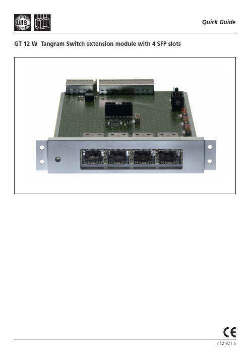
Quick Guide GT 12 W Tangram Switch extension module with 4 SFP slots1) Remove the right and the left part of the front panel by pulling at the side of either panel.2) Disconnect the cable at the backside of the right front panel.3) Remove the screws at both sides of the upper front cover.4) Insert the GT 12 W module into the empty slot.5) Fix the GT-module with the previously removed screws.Reconnect the cable and reapply the front panels.6) Insert the SFP modules into the slots, e.g. WISI OSFP 019/12excellence in digital ...WISI Communications GmbH & Co. KGEmpfangs- und VerteiltechnikWilhelm-Sihn-Straße 5-775223 Niefern-Oeschelbronn, GermanyTel.: +49 7233 - 66-0, Fax: 66-350,E-mail:************,http://www.wisi.deTechnical Modifications reserved. WISI cannot be held liable for any printing error.3. Support and further informationFor further information and help, please contact our support organisations:E-mail: ***********************Telephone: +49 (0)7233 / 66-621User manual and installation guide The user manual and the installation guide is available at the Website www.wisi.de.2. Technical dataStreaming InterfaceData format Unicast/Multicast SPTS/MPTS Encapsulation MPEG-TS over UDP/RTP P rotocol Internet P rotocolConnectors SF P cageStandard depends on SFP used Bitrate up to 1000 MbpsGeneralHousingType P CBSize 220 x 100 mmConnectorsBackplane 110 pin, Harting Type B22 55 pin, Harting Type C Transport Stream 4x SFP cageOperating conditionsOperating temperature range 0°C to +55°CStorage temperature range -25°C to +75°CHumidity non condensing < 95%。
文联工程公司三位自动交换器手册(模式WSSMSW3)说明书
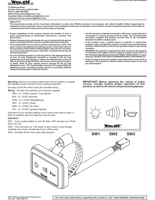
For warranty information regarding this product, visit /warranty ©2013 Whelen Engineering Company Inc.Form No. 14696 (052113) 3 Position Motorcycle Switch (Model WSSMSW3)Safety FirstThis document provides all the necessary information to allow your Whelen product to be properly and safely installed.Before beginning the installation and/or operation of your new product,the installation technician and operator must read this manual completely.Important information is contained herein that could prevent serious injury or damage.Mounting:Select a mounting location that will not interfere or impedethe operation and/or function of any existing equipment.Securely mount the switch using the provided clamp.Wiring:All fuses and switches are customer supplied.RED - to +12VDC (power) / Fuse @10ABLK - to -12VDC (ground)ORG - to +12VDC (Backlighting)GRY - to -12VDC (Siren)BRN - to -12VDC (Air Horn)YEL - to +12VDC (auxiliary lighting)Important! If your auxiliary lighting circuit draws more than 8 amps, arelay of sufficient size and capacity must be used.Operation:SW1 -Turns auxiliary lights on and off. Note: SW1 will also turn off thesiren if it is on.SW2 -Turns the siren on.This switch is also used to cycle throughavailable siren tones. Double-tap to turn off the siren.SW3 -Activates theIMPORTANT!Before returning the vehicle to active service,visually confirm proper operation of this product,as well as all vehicle components/equipment.•Proper installation of this product requires the installer to have a good understanding of automotive electronics,systems and procedures.•Whelen Engineering recommends the use of waterproof butt splices and/or connectors if that connector could be exposed to moisture.•The installer MUST be sure that no vehicle components or other vital parts could be damaged by the drilling process.Check both sides of the mounting surface before drilling begins.Also de-burr any holes and remove any metal shards or remnants.Install grommets into all wire passage holes.•Do not install this product or route any wires in the deployment area of your air bag.Equipment mounted or located in the air bag deployment area will damage or reduce the effectiveness of the air bag,or become a projectile that could cause serious personal injury or death.Refer to your vehicle owner's manual for the air bag deployment area.The User/Installer assumes full responsibility to determine proper mounting location,based on providing ultimate safety to all passengers inside the vehicle.•For this product to operate at maximum efficiency,a good electrical connection to chassis ground must be made.The recommended procedure requires the product ground wire to be connected directly to the NEG (-)battery post.•If this product uses a remote device to activate or control this product,make sure that this control is located in an area that allows both the vehicle and the control to be operated safely in any driving condition.•WARNING!All customer supplied wires that connect to the positive (+)terminal of the battery must be sized to supply at least 125%of the maximum operating current and FUSED “at the battery”to carry that load.DO NOT USE CIRCUIT BREAKERS WITH THIS PRODUCT!•Failure to follow these precautions and instructions could result in damage to the product or vehicle and/or serious injury to you and your passengers!®ENGINEERING COMPANY INC.51 Winthrop RoadChester, Connecticut 06412-0684Phone: (860) 526-9504SalesEmail:*******************CanadianSales:************************CustomerService:*******************Warnings to InstallersWhelen’s emergency vehicle warning devices must be properly mounted and wired in order to be effective and safe. Read and follow all of Whelen’s written instructions when installing or using this device. Emergency vehicles are often operated under high speed stressful conditions which must be accounted for when installing all emergency warning devices. Controls should be placed within convenient reach of the operator so that he can operate the system without taking his eyes off the roadway. Emergency warning devices can require high electrical voltages and/or currents. Properly protect and use caution around live electrical connections.Grounding or shorting of electrical connections can cause high current arcing, which can cause personal injury and/or vehicle damage, including fire. Many electronic devices used in emergency vehicles can create or be affected by electromagnetic interference.Therefore, after installation of any electronic device it is necessary to test all electronic equipment simultaneously to insure that they operate free of interference from other components within the vehicle. Never power emergency warning equipment from the same circuit or share the same grounding circuit with radio communication equipment.All devices should be mounted in accordance with the manufacturer’s instructions and securely fastened to vehicle elements of sufficient strength to withstand the forces applied to the device. Driver and/or passenger air bags (SRS) will affect the way equipment should be mounted.This device should be mounted by permanent installation and within the zones specified by the vehicle manufacturer, if any.Any device mounted in the deployment area of an air bag will damage or reduce the effectiveness of the air bag and may damage or dislodge the device. Installer must be sure that this device, its mounting hardware and electrical supply wiring does not interfere with the air bag or the SRS wiring or sensors. Mounting the unit inside the vehicle by a method other than permanent installation is not recommended as unit may become dislodged during swerving; sudden braking or collision. Failure to follow instructions can result in personal injury. Whelen assumes no liability for any loss resulting from the use of this warning device. PROPER INSTALLATION COMBINED WITH OPERATOR TRAINING IN THE PROPER USE OF EMERGENCY WARNING DEVICES IS ESSENTIAL TO INSURE THE SAFETY OF EMERGENCY PERSONNEL AND THE PUBLIC.Warnings to UsersWhelen’s emergency vehicle warning devices are intended to alert other operators and pedestrians to the presence and operation of emergency vehicles and personnel. However, the use of this or any other Whelen emergency warning device does not guarantee that you will have the right-of-way or that other drivers and pedestrians will properly heed an emergency warning signal. Never assume you have the right-of-way. It is your responsibility to proceed safely before entering an intersection, driving against traffic, responding at a high rate of speed, or walking on or around traffic lanes. Emergency vehicle warning devices should be tested on a daily basis to ensure that they operate properly. When in actual use, the operator must ensure that both visual and audible warnings are not blocked by vehicle components (i.e.: open trunks or compartment doors), people, vehicles, or other obstructions. It is the user’s responsibility to understand and obey all laws regarding emergency warning devices.The user should be familiar with all applicable laws and regulations prior to the use of any emergency vehicle warning device. Whelen’s audible warning devices are designed to project sound in a forward direction away from the vehicle occupants. However, because sustained periodic exposure to loud sounds can cause hearing loss, all audible warning devices should be installed and operated in accordance with the standards established by the National Fire Protection Association.。
wisLink工业交换机

•严酷环境下零丢包技术
可靠设计
•全工业级芯片 •全球一线品牌: Broadcom,TI,Freescale,Micron,MAXIM,Linear, Molex,JST,TE,Pulse,Avago,… … •PCB:兴森快捷 •机箱:上海宝钢板材
•电源:全定制工业电源
可靠设计
选型测试
光模块选型
可靠设计
第三方HALT测试
高加速寿命实验
可靠设计
第三方HALT测试
可靠生产
产品可追溯系统
可靠生产
全进口生产线
•英国DEK全自动丝网印刷机
•德国ERSA回流炉 •瑞典MYDATA,美国UNIVERSAL高速贴片机 •日本欧姆龙AOI检测仪
可靠生产
全进口测试仪
•美国Spirent的Smartbit-600B •满端口、全线速测试
首页工业交换机产品介绍july2015大纲公司介绍01交换机产品业绩03交换机产品资质02产品理念04可靠研发05可靠生产06可靠质控07公司介绍现状定位现状定位历史变电站二次主要产品工业交换机网分及录波pq源于金智完全独立系统智能辅助设备供应商qpmu时间同步系统资质荷兰kema认证国网a级认证资质国网智能变电站专用交换机认证国网网络安全认证资质交换机相关专利工信部入网证资质序号专利类型专利号专利名称1发明zl2012100353682一种数字化变电站智能控制设备的以太网收发器实现方法2发明zl2012100357467具备sdh网络精确对时功能的专用网络交换方法及设备3发明zl2012100357452基于sdh网络实现广域保护系统精确网络对时方法4发明zl2009100698332一种基于iec61850模型的交换机自动配置方法5实用新型zl2014201972044一种数字化变电站交换机在线监测装置6实用新型zl2014201972612一种支持功能扩展的交换机7实用新型zl2014200284009可根据报文类型自动调整发送策略的多网口fpga网卡8实用新型zl2009200978610具有精确对时功能的交换机产品序列站控层三层交换机导轨环网交换机变电站用交换机完整解决方案过程层交换机站控层交换机智能变电站专用交换机业绩交换机唯一供应商金智科技交换机网分录波pqpmu唯一供应商磐能电力南瑞继保主客户南瑞继保国电南瑞长园深瑞主要客户北京四方业绩向金智科技累计供货138种型号约13000台含国网集中采购6000台向磐能电力累计供货26种型号约1100台2013年至今
工业级交换式集线器W4S1-03B 05B 05C 说明书
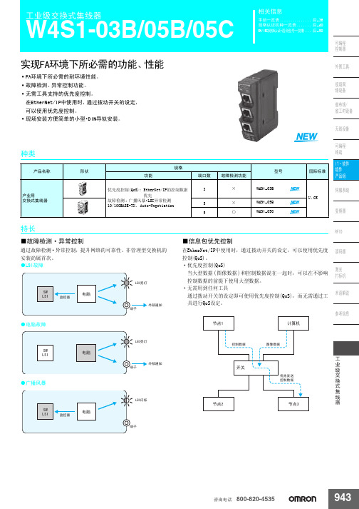
实现FA环境下所必需的功能、性能•FA环境下所必需的耐环境性能。
•故障检测、异常控制功能。
•无需工具支持的优先度控制。
在EtherNet/IP中使用时,通过拨动开关的设定,
可以使用优先度控制。
•现场安装方便简单的小型·DIN导轨安装。
■故障检测·异常控制
通过故障检测·异常控制,提升网络的可靠性。
非管理型交换机的安装尚属首次。
●LSI故障
●电脑故障
●广播风暴■信息包优先控制
在EtherNet/IP中使用时,通过拨动开关的设定,可以使用优先度控制(QoS)。
·优先度控制(QoS)
当大型数据(图像数据)和控制数据混在一起时,可以在不影响控制数据的前提下使用大型数据。
·无需用到任何工具
通过拨动开关的设定即可使用优先度控制(QoS),而无需通过工具进行QoS设定。
䆶⬉䆱 800-820-4535。
- 1、下载文档前请自行甄别文档内容的完整性,平台不提供额外的编辑、内容补充、找答案等附加服务。
- 2、"仅部分预览"的文档,不可在线预览部分如存在完整性等问题,可反馈申请退款(可完整预览的文档不适用该条件!)。
- 3、如文档侵犯您的权益,请联系客服反馈,我们会尽快为您处理(人工客服工作时间:9:00-18:30)。
wisLink W-1600 工业交换机技术说明书(V1.1)
1. 概述
wisLink W-1600 工业交换机是针对工业现场需要而开发的一种工业网络交换设备,用于工业 现场的以太网设备的互连,能够无缝地集成 10BASE-T 和 100BASE-TX 的设备,使之共处于一个网 络内而无须更改网络结构,提供了一种经济、有效的快速以太网解决方案。该装置采用了专用的工 业级低功耗交换芯片组,保证交换机在工业温度范围内正常工作。同时该交换机具有大容量的数据 缓冲区和 MAC 地址区,以及非常高的交换带宽,从而使每一个口都达到线速(100Mbps)数据流 量。
1 个 100BaseFX(SC/ST 可选)
光纤:
支持距离 波长 最小 TX 输出 最大 TX 输出 灵敏度
15 km-45km(单模),2 km(多模) 1310nm -12 dBm (单模), -19 dBm (多模) -5 dBm (单模), -14 dBm (多模) -37 dBm (单模),-33 dBm (多模)
第 1 页 共 4页
wisLink W-1600 工业交换机技术说明书(V1.1)
包交换速率 背板带宽 数据转发类型 流量控制 地址表大小 延迟
接口:
RJ45 口
电源:
输入电压 连接 最大功耗 过载电流保护 反向电压输入保护
机械特性:
包装及防护等级 尺寸
工作环境:
工作温度 工作相对湿度
抗干扰特性:
wisLink W-1600 在设计中考虑工业场合的应用需求和习惯,采用交直流供电方式,直流供电 让交换机和工业设备采用相同的电压输入,增加了可靠性,减少了施工复杂性。采用网线后出线的 方式,使得网线的布置整洁、美观;同时为了方便巡视,wisLink W-1600 前面板设置了显示各个网 口工作状态的灯,使得交换机的工作状态一目了然。由于 wisLink W-1600 针对工业用户,我们在设 计上严格按照 IEC-1613、IEC61000-6-5 以及 IEC61850-3 的标准,以满足工业现场的抗电磁干扰的 需求。在交换性能上,wisLink W-1600 完全满足 RFC2899 规定的交换性能要求。
4.1. 装置的机械安装....................................................................................................................................3 4.2. 装置的背板说明....................................................................................................................................4 4.3. 装置的面板说明................................................................................................................................大功耗
DC220V/110V(自适应) 接线端子 3W
第 1 页 共3页
wisLink W-100 工业交换机装置技术说明书(V1.0)
过载电流保护 反向电压输入保护
机械特性:
包装及防护等级 尺寸
工作环境:
工作温度 工作相对湿度
抗干扰特性:
抗干扰性能 绝缘耐压标准
支持,最大可承受 2.5 A 支持
wisLink W-100 工业交换机 技术说明书
版本:V1.0
江苏金智科技股份有限公司
wisLink W-100 工业交换机装置技术说明书(V1.0)
目录
1. 特性 ................................................................................................................................................................... 1 2. 装置技术参数.................................................................................................................................................... 1 3. 装置尺寸图........................................................................................................................................................ 2 4. 装置接线和面板说明........................................................................................................................................ 3
全封闭合金外壳,符合 IP 30 40MM×79MM×136.5MM(宽×深×高)
-40 ~ 80°C (14 ~ 158°F) 10% ~ 90% ,无凝结
符合国标 GB6162 满足部标 DL478
3. 装置尺寸图
第 2 页 共 3页
wisLink W-100 工业交换机装置技术说明书(V1.0)
2. 装置技术参数
交换技术:
符合标准
IEEE802.3 10BASE-T IEEE802.3u 100BASE-TX/100BASE-FX IEEE802.3x Flow Control and Back pressure IEEE802.3ad Port trunk with LACP IEEE802.1p Class of service IEEE802.1q
包交换速率 数据转发类型 流量控制 地址表大小 延迟
10M-14880 pps、100M-148800pps、1000M-1488000pps 存储转发 全双工 IEEE802.3x,半双工背压式 1K、自动学习 < 5ms
接口:
RJ45 口 光纤口
2 个 10/100BaseT(X),全/半双工模式自动协商,自动 MDI/MDIX 连接
第 3 页 共3页
wisLink W-1600 工业交换机 技术说明书
版本:V1.1
江苏金智科技股份有限公司
wisLink W-1600 工业交换机技术说明书(V1.1)
目录
1. 概述 ................................................................................................................................................................... 1 2. 装置技术参数.................................................................................................................................................... 1 3. 装置尺寸图........................................................................................................................................................ 2 4. 装置的机械安装和接线.................................................................................................................................... 3
wisLink W-1600 工业交换机具有以下特点: 16 个 10/100Mbps 端口 每个端口均支持全/半双工模式 网络配置的自动学习 流量控制,保护数据避免丢失 半双工模式背压流控 端口 MDI/MDIX 自动适应功能 简明内置的 LED 指示灯 交直流自适应供电方式 采用 1U 标准机箱,安装方便
如需相关产品、服务和支持的更多信息,请访问金智科技网 站/。
本公司有权对本说明书的内容进行定期变更,恕不另行通知。变更内容将会补充 到新版本的说明书中。
_____________________________________________________________
wisLink W-100 工业交换机装置技术说明书(V1.0)
1. 特性
1 个 100Base-FX 光纤端口(SC/ST 可选) 2 个 10/100Base-T,可以接入具有以太网的分散装置 DC220/110V 自适应供电 Auto MDI/MDI-X MAC 地址 1K,缓冲内存 64K 导轨安装,安装方便 工业级温度范围-40~+80 度
2. 装置技术参数
交换技术:
符合标准
IEEE802.3 10BASE-T IEEE802.3u 100BASE-TX/100BASE-FX IEEE802.3x Flow Control and Back pressure IEEE802.3ad Port trunk with LACP IEEE802.1p Class of service IEEE802.1q VLAN