中性室内温湿度传感器说明书模板
湿度与温度传感器产品说明书
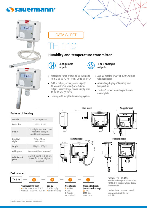
• Measuring range from 5 to 95 %HR and from 0 to 50 °C (1) or from -20 to +80 °C (2)• 0-10 V output, active, power supply24 Vac/Vdc (3-4 wires) or 4-20 mAoutput, passive loop, power supply from 16 to 30 Vdc (2 wires)• Housing with simplified mounting system• ABS V0 housing IP65(2) or IP20(1), with orwithout display • Alternating display of humidity and temperature • “¼ turn” system mounting with wall-mount plateFeatures of housingPart numberPower supply / Output A : Active 24 Vac/Vdc – 0-10 V P : Passive – 16/30 Vdc - 4-20 mA Display O : With display N : Without displayType of probe S : Ambient A : Duct D : Remote ES : StandardExample: TH 110-ANSHumidity and temperature transmitter TH 110, 0-10 V active, without display, ambient model.Caution: the TH 110 – POES model (passive with display) is not availableConfigurable outputs1 or2 analogue outputs(1)Ambient model / (2) Duct, remote and standard model.Ambient modelDuct modelProbe cable length (remote models only)( ): 2 m 05M: 5 m 10M: 10 mStandard modelTechnical specificationsConnectionsInside the front housing 1. Active switch (S1)2. Inactive switch3. LCC-S software connection4. Output terminal block5. Power supply terminal block6.Cable glandSimplified calibrationElectronic board and measuring element connected to the front side of the sensor, which allows toconfigure and calibrate your device without causing any damage.12Removable front face Fixed back housingGeneral features*Can be configured by switch.**All the accuracy indicated in this technical datasheet were stated in laboratory conditions, and can be guaranteed for measurements carried out in the same conditions, or carried out with calibration compensation.Measuring range Analogue output*654316354(standard model)Electrical connections as per NFC15-100 standardsThis connection must be made by a qualified and trained technician.IRH Vdc IT Vdc 1 2 hilos - +- +IRH Vdc IT Vdc IRH VdcIT Vdc IRH VdcIT Vdc symbol:F T _E N – T H 110 – 06/01/23 – N o n -c o n t r a c t u a ld o c u me n t – W e r e s e r v e t h e r i g h t t o m o d if y t h e c h a r a c t e r i s t i c s o f o u r p r o d u c t s w i t h o u t p r i o r n o t i c e .Only the accessories supplied with the device must be used.T o configure the transmitter , it must not be energized. Then, you can make the settings required, with the DIP switches (as shown on the drawing below).When the transmitter is configured, you can power it up.Please follow carefully the combinations beside with the DIP switch. If the combination is wrongly done, the following message will appear on the display of the transmitter “CONF ERROR”. In that case, you will have to unplug the transmitter , place the DIP switches correctly, and then power the transmitter up.1234Off OnActive switchUnit settingOutput setting On-off switch1234Active switch (S1)Please refer to the user manual of the LCC-S software to make the configuration.Set the DIP switches as shown beside. Connect the cable of the LCC-S to the connection of the transmitter .PC configurationSettings and use of the transmitterIt is possible to set the measuring ranges and the unit of the instrument either by switch and/or via software.Configurationis correctly installed. Ambient model does not have any mounting plate. 4 fixing holes are present inside the back Configuration via LCC-S software (option)It is possible to configure intermediate ranges, an offset...Example: for a 0-100 °C transmitter, minimum delta is 20 °C.The instrument can be configured from 0 to +20 °C or from -10 to +10 °C. In order to compensate a possible drift of the sensor, it is possible to add an offset to the displayed value by the TH 110 transmitter: it shows 48% RH, a standard instrument shows 45% RH. It is then possible, via the software, to integrate an offset of -3 to the displayed value by the TH 110 instrument.The configuration of the parameters can be done either with the DIP switch or via software (you can not combine both solutions).WarrantyInstruments have 1-year guarantee for any manufacturing defect.Maintenance:• Avoid any aggressive solvent.• Protect the transmitter and its probes from any cleaning product containing formalin, that may be used for cleaning rooms or ducts.Precautions for use: always use the device in accordancewith its intended use and within parameters described in the technical features in order not to compromise the protection ensured by the device.。
AHT20-F 产品手册 - 温湿度传感器说明书
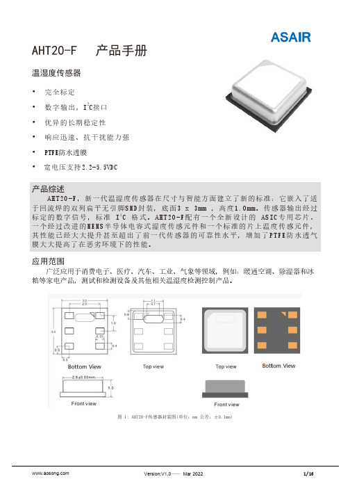
AHT20-F 产品手册温湿度传感器•完全标定•数字输出,I 2C接口•优异的长期稳定性•响应迅速、抗干扰能力强•PTFE防水透膜•宽电压支持2.2-5.5VDC产品综述AHT20-F,新一代温湿度传感器在尺寸与智能方面建立了新的标准:它嵌入了适于回流焊的双列扁平无引脚SMD封装,底面3 x 3mm ,高度1.0mm。
传感器输出经过标定的数字信号,标准 I2C 格式。
AHT20-F配有一个全新设计的ASIC专用芯片、一个经过改进的MEMS半导体电容式湿度传感元件和一个标准的片上温度传感元件,其性能已经大大提升甚至超出了前一代传感器的可靠性水平,增加了PTFE防水透气膜大大提高了在恶劣环境下的性能。
应用范围广泛应用于消费电子、医疗、汽车、工业、气象等领域,例如:暖通空调、除湿器和冰箱等家电产品,测试和检测设备及其他相关温湿度检测控制产品。
图 1: AHT20-F传感器封装图(单位:mm 公差:±0.1mm)传感器性能相对湿度表1 湿度特性表图2 25℃时相对湿度的典型误差和最大误差电气特性表2 电气特性1此精度为出厂检验时,传感器在25℃供电电压为3.3V条件下的测试精度。
此数值不包括迟滞和非线性,并只适用于非冷凝条件。
225℃和1m/s气流条件下,达到一阶响应63%所需时间。
3正常工作范围:0-80%RH,超出此范围,传感器读数会有偏差(在90%RH湿度下60小时后,漂移>3%RH)。
工作范围进一步限定在-40–85℃。
4如果传感器周围有挥发性溶剂、带刺激性气味的胶带、粘合剂以及包装材料,读数可能会偏移。
详细说明请参“设计指南”。
5供电电流和功耗的最小值和最大值都是基于VDD=3.3V和T<60℃的条件。
平均值为每两秒中进行一次测量的数值。
温度表3 温度特性表图3 温度典型误差和最大误差包装信息表4 包装信息6响应时间取决于传感器基片的导热率。
AHT20-F 用户指南1.扩充性能1.1 工作条件传感器在所建议工作范围内,性能稳定,见图4。
温湿度控制器使用说明书

恒温恒湿控制系统使用说明书天英科技创新协会一、 概述 恒湿恒温控制器用于封闭空间温湿度控制,通过传感器采集,与执行设备构成闭环回流系统。
温湿度传感器采用模拟器件设计,其抗干扰能力强,传输距离远,精度准确。
并具备抗潮湿、抗腐蚀等优点。
设备面板如下图所示:恒温恒湿控制器加湿温度湿度▲▲●加湿恒湿去湿定时加湿加温恒温制冷风机%RH 菜单 设定 设定 加数 减数 确定℃温度上限 温度下限 湿度上限 湿度下限实时温度实时湿度二、 功能特点1、 上电校准功能,可对温湿度传感器进行自动校准;2、 湿度范围可根据客户要求任意设定。
示例:如设定上限湿度95%,下限湿度75%,也就是说湿度在75%-95%之间范围内循环加湿和去湿动作。
如湿度低于74%值,立即启动加湿设备工作。
如湿度高于96%值,立即启动去湿设备工作;3、 定时模式+自动模式双重控制;4、 手动一键加湿;5、 可设定温湿度会差范围;6、 特殊客户要求型号:温度+湿度自动控制系统可定制;三、仪表输出四路继电器输出,每个继电器最大负载AC220V/10A。
四、技术指标1、测控范围:温度:0~100℃湿度:0~100%RH2、控温灵敏度:±0.1℃控湿灵敏度:±1%RH3、测温精度:±0.5%F.S.±1个字测湿精度:±3%RH F.S.±1个字4、电控定时范围:工作时间--0~99秒、0~99分停止时间--0~99秒、0~99分5、控制输出接点最大功率:控温、电流5A/AC220V;控湿、电流5A/AC220V;控时、电流5A/AC220V6、仪表工作环境:0~45℃,相对湿度不大于85%7、仪表工作电压:AC220V±10% 50HZ;仪表功耗:约6瓦五、使用方法时间按一下间和开启时间,通过加数、减数键设定大小,按确定键保存并退出。
湿度温度仪产品说明书
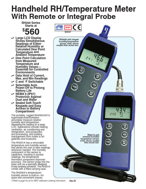
Hu-21RH200 Series Starts at$560RH200A with integral humidity/temperature sensor, $560, shown smaller than actual size.Handheld RH/Temperature MeterWith Remote or Integral ProbeߜLarge LCD Display Shows Simultaneous Readings of Either Relative Humidity or Calculated Dew Point Temperature and Ambient Temperature ߜDew Point Calculation from Measured Temperature and Humidity Values—Essential for Controlled EnvironmentsߜData Hold of Current, Max, and Min Readings ߜC and °F Switchable ߜSelectable AutoPower-Off to Prolong Battery Life ߜNEMA 6 (IP67)Protection Against Dust and Water ߜSealed Soft-Touch Keypads and Easy Access to Battery CompartmentRH201A with external humidity/temperature sensor,$750, shown smallerthan actual size.The portable, rugged RH200A/201A hygrometer/thermometers accurately measure relative humidity and temperature,displaying the reading on a large LCD. Applications include heating,ventilation, air conditioning and refrigeration, food production and processing, and building management from hotels to art galleries and museums.The RH201A has a removable temperature and humidity sensor that allows the user to take readings whenever needed. The humidity component of this sensor is capacitive, resulting in quicker readings; the temperaturethermistor component improves accuracy. The sensor plugs into the base unit via a specially designed 8-way lumberg connector. The RH201A comes with a fitted carrying case.The RH200A’s temperature/humidity sensor is built-in—for quick and convenient checks.† Refer to page Hu-22 for NIST calibration ordering information.Hu-22Ordering Examples: RH201A, hygrometer/thermometer with remote probe and carrying case, CAL-3-HU,NIST-traceable calibration,$750 + 135 = $885.RH200A, hygrometer/thermometer with integral probe, RCC-200A,hard carrying case, RH200-RB,protective rubber boot with wrist strap, $560 + 42 + 16 = $618.RH200A, $560,shown smaller than actual size.RH201A, $750,shown smaller than actual size.SpecificationsSensors:Humidity: HC 1000 capacitive sensor Temperature: 10K thermistor sensorMeasurement RangeHumidity: 0 to 100% RHTemperature: -20 to 60°C (-4 to 140°F)Scales: RH, °C, °F, DP Resolution:Humidity: 0.1% RH Temperature: 0.1°Accuracy:Humidity: 0 to 90% RH: ±2% RH;90 to 100% RH: ±3% RHTemperature: ±0.5°C (±0.9°F)Environmental Protection: IP67, BS5490, IEC529Operating Temperature Range: -20 to 60°C (-4 to 140°F)Response Time: 2 minutes in moving airBattery Type: 2 “AA” alkaline (included)Battery Life (Continuous):RH201A: 250-hr RH200A: 300-hr Dimensions:RH200A/RH201A:68/79 W x 183 L x 31 mm D (2.68/3.11 x 7.2 x 1.22")RH201A-RP (Sensor):200 L x 23 mm Dia. (7.8 x 0.92")Weight:RH200A and RH201A: 270 g (9.5 oz)RH201A-RP: 126 g (4.4 oz)CANADA www.omega.ca Laval(Quebec) 1-800-TC-OMEGA UNITED KINGDOM www. Manchester, England0800-488-488GERMANY www.omega.deDeckenpfronn, Germany************FRANCE www.omega.frGuyancourt, France088-466-342BENELUX www.omega.nl Amstelveen, NL 0800-099-33-44UNITED STATES 1-800-TC-OMEGA Stamford, CT.CZECH REPUBLIC www.omegaeng.cz Karviná, Czech Republic596-311-899TemperatureCalibrators, Connectors, General Test and MeasurementInstruments, Glass Bulb Thermometers, Handheld Instruments for Temperature Measurement, Ice Point References,Indicating Labels, Crayons, Cements and Lacquers, Infrared Temperature Measurement Instruments, Recorders Relative Humidity Measurement Instruments, RTD Probes, Elements and Assemblies, Temperature & Process Meters, Timers and Counters, Temperature and Process Controllers and Power Switching Devices, Thermistor Elements, Probes andAssemblies,Thermocouples Thermowells and Head and Well Assemblies, Transmitters, WirePressure, Strain and ForceDisplacement Transducers, Dynamic Measurement Force Sensors, Instrumentation for Pressure and Strain Measurements, Load Cells, Pressure Gauges, PressureReference Section, Pressure Switches, Pressure Transducers, Proximity Transducers, Regulators,Strain Gages, Torque Transducers, ValvespH and ConductivityConductivity Instrumentation, Dissolved OxygenInstrumentation, Environmental Instrumentation, pH Electrodes and Instruments, Water and Soil Analysis InstrumentationHeatersBand Heaters, Cartridge Heaters, Circulation Heaters, Comfort Heaters, Controllers, Meters and SwitchingDevices, Flexible Heaters, General Test and Measurement Instruments, Heater Hook-up Wire, Heating Cable Systems, Immersion Heaters, Process Air and Duct, Heaters, Radiant Heaters, Strip Heaters, Tubular HeatersFlow and LevelAir Velocity Indicators, Doppler Flowmeters, LevelMeasurement, Magnetic Flowmeters, Mass Flowmeters,Pitot Tubes, Pumps, Rotameters, Turbine and Paddle Wheel Flowmeters, Ultrasonic Flowmeters, Valves, Variable Area Flowmeters, Vortex Shedding FlowmetersData AcquisitionAuto-Dialers and Alarm Monitoring Systems, Communication Products and Converters, Data Acquisition and Analysis Software, Data LoggersPlug-in Cards, Signal Conditioners, USB, RS232, RS485 and Parallel Port Data Acquisition Systems, Wireless Transmitters and Receivers。
湿度 温度传感器HX400系列产品说明书
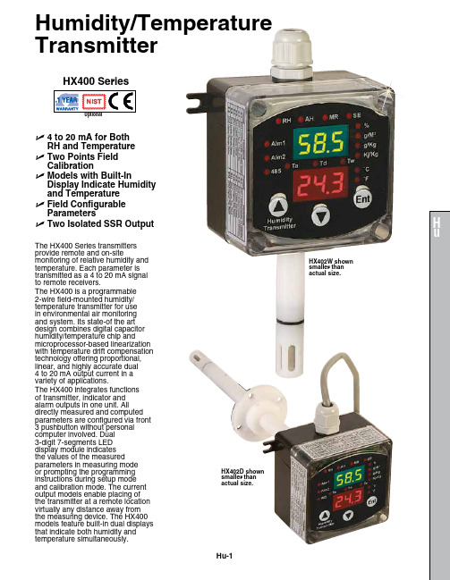
Humidity/Temperature TransmitterHu-1U 4 to 20 mA for Both RH and Temperature U T wo Points Field Calibration U M odels with Built-InDisplay Indicate Humidity and Temperature UF ield Configurable Parameters U Two Isolated SSR OutputHX400 SeriesThe HX400 Series transmitters provide remote and on‑sitemonitoring of relative humidity and temperature. Each parameter is transmitted as a 4 to 20 mA signal to remote receivers.The HX400 is a programmable 2‑wire field‑mounted humidity/temperature transmitter for use in environmental air monitoring and system. Its state‑of the art design combines digital capacitor humidity/temperature chip andmicroprocessor‑based linearization with temperature drift compensation technology offering proportional, linear, and highly accurate dual 4 to 20 mA output current in a variety of applications.The HX400 integrates functions of transmitter, indicator and alarm outputs in one unit. All directly measured and computed parameters are configured via front 3 pushbutton without personal computer involved. Dual 3‑digit 7‑segments LED display module indicates the values of the measured parameters in measuring mode or prompting the programming instructions during setup mode and calibration mode. The current output models enable placing of the transmitter at a remote location virtually any distance away from the measuring device. The HX400 models feature built‑in dual displays that indicate both humidity andtemperature simultaneously.HX402W shown smaller than actual size.HX402D shown smaller thanactual size.Hu-2SpecificationsLoop Power: 12 to 32 Vdc; dual 4 to 20 mA loop current; reverse polarity protected (Vloop = 24 Vdc, Tamb = 23 ±2°C, Rload = 250 Ω)Dual Isolated Solid State Relay Output: For output #1 and output #2; 15 mA maximum, 40 Vdc maximumAccuracy and Range of Output Current: ±0.02 mA; 4 to 20 mA (both channels)Accuracy @ 23°C and Scaleable Measurement Range: Without field calibrationRelative Humidity (RH): ±2%; 0 to 100%Temperature: ±0.5°C (0.9ºF)Dew Point: ±2°C (3.6ºF)Wet Bulb Temperature: ±2°C (3.6ºF), ‑20 to 80°C (‑4 to 176ºF)Repeatability of Relative Humidity and Temperature: ±1% RH, ±0.1°C Display Resolution: 0.1% RH, 0.1°C (temperature < 100°C)Response: 10 seconds (relative humidity); 30 seconds maximum (temperature)Filtering Ability of Sensor Cap: Stainless steel wire mesh; 0.05 mm Type of Fluid: Air and neutral gases Configuration Operation:Front 3 pushbutton with dual high bright 3‑digit LED moduleWorking Temperature:Electronics Device: ‑20 to 70°C (‑4 to 158ºF)Sensing Probe: ‑40 to 100°C (‑40 to 212ºF)Dual Miniature Loop-PoweredIndicators: Dual 3‑digits LED (green for humidity; red for temperature)Reading Rate: 1 update per secondDisplay AccuracyRelative Humidity: ±2% RH Temperature: ±0.5°C (1°F)Display Resolution:Relative Humidity: 0.1% RH Temperature: 0.1°C (0.2°F)Housing Material: POM(sensing probe); polycarbonate (electronics device)Protection: NEMA 4 (IP65) (electronic device); IP40 (sensing probe)Dimensions: 110 W x 80 L x 56 mm D (4.3 x 3.2 x 2.2")Weight: 250 g (8.8 oz)Probe Dimensions:Wall Mount Unit: L = 73 mm (2.87"), D = 15.5 mm (0.61")Remote Mount Unit: L = 100 mm (3.94"), D = 15.5 mm (0.61"), 100 cm (39.4") cable, 5.3 (0.21") diameter cableDuct Mount Unit: L = 200 mm (7.87"), D = 15.5 mm (0.61")RHCN-7000 U B right Green 3-Digit LED Display U 0 to 1 or 0 to 3 Vdc, 4 to 20 mA Inputs U 8 Amp Relay Output U S imple On/Off Control U C ompatible with RH Transmitters U O ptional RH ProbeRHCN-7001。
温湿度传感器产品说明书
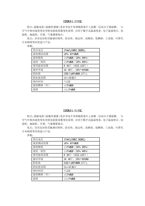
特点:湿敏电阻(湿敏传感器)是在导电半导体陶瓷基片上涂履一层高分子感湿膜,与空气中相对湿度变化导致电阻值系数变化原理。
应用于数字式温湿度表、电子温湿度计、加湿机、抽湿机、空调、气象测量场合。
优点:具有良好的灵敏感应特性、防水性、稳定性、高精度、低飘移,工业级,可替代日本韩国等同类进口产品。
SHR01-313K特点:湿敏电阻(湿敏传感器)是在导电半导体陶瓷基片上涂履一层高分子感湿膜,与空气中相对湿度变化导致电阻值系数变化原理。
应用于数字式温湿度表、电子温湿度计、加湿机、抽湿机、空调、气象测量场合。
优点:具有良好的灵敏感应特性、防水性、稳定性、高精度、低飘移,工业级,可替代日本韩国等同类进口产品。
特点:湿敏电阻(湿敏传感器)是在导电半导体陶瓷基片上涂履一层高分子感湿膜,与空气中相对湿度变化导致电阻值系数变化原理。
应用于数字式温湿度表、电子温湿度计、加湿机、抽湿机、空调、气象测量场合。
优点:具有良好的灵敏感应特性、防水性、稳定性、高精度、低飘移,高性价比,可替代日本神荣、北陆、韩国等同类进口产品。
SHR02-313K特点:湿敏电阻(湿敏传感器)是在导电半导体陶瓷基片上涂履一层高分子感湿膜,与空气中相对湿度变化导致电阻值系数变化原理。
应用于数字式温湿度表、电子温湿度计、加湿机、抽湿机、空调、气象测量场合。
优点:具有良好的灵敏感应特性、防水性、稳定性、高精度、低飘移,高性价比,可替代日本神荣、北陆、韩国进口等同类产品。
特点:湿敏电阻(湿敏传感器)是在导电半导体陶瓷基片上涂履一层高分子感湿膜,与空气中相对湿度变化导致电阻值系数变化原理。
应用于数字式温湿度表、电子温湿度计、加湿机、抽湿机、空调、气象测量场合。
优点:具有良好的灵敏感应特性、防水性、稳定性、高精度、低飘移,高性价比,可替代日本神荣、北陆、韩国进口等同类产品。
特点:电容式温湿度模块是将湿度传感器非线性电阻值转换为线性电压信号输出,体积小,使用方便,精度高。
温湿度传感器说明书
温湿度传感器说明书首部分:引言温湿度传感器是一种用于测量环境中温度和湿度的仪器。
它采用先进的技术和设计,可以提供高精度、快速响应和可靠性的温湿度数据。
本说明书将详细介绍温湿度传感器的工作原理、使用方法和注意事项。
第一部分:工作原理温湿度传感器利用测量元件和电路来获取环境中的温度和湿度数据。
测量元件通常是基于电容、电阻或半导体等原理,并通过准确测量元件的物理变化来计算温度和湿度值。
电路部分则负责放大、滤波和转换信号,以提供数字或模拟输出。
第二部分:使用方法1. 安装温湿度传感器通常需要正确安装才能获得准确的数据。
请将传感器放置在需要测量温湿度的位置,尽量避免遮挡或受到外部干扰。
保持传感器与被测区域的充分接触,并确保传感器与其他设备之间有足够的空间。
2. 连接温湿度传感器通常具有标准的接口和电源要求。
根据传感器的型号和要求,正确连接传感器到检测或控制系统。
注意接线的正确性和稳定性,以免影响数据的准确性和传输质量。
3. 校准为了获得更准确的数据,定期对温湿度传感器进行校准是必要的。
校准可以通过专业的仪器或参照标准数据进行。
校准过程应在环境条件稳定的情况下进行,并确保校准后的传感器能够正常工作。
第三部分:注意事项1. 温度和湿度范围不同型号和品牌的温湿度传感器具有不同的工作范围。
在选择和使用传感器时,请仔细阅读产品说明书,并确保传感器的工作范围符合您的需求。
超出工作范围可能导致数据的不准确或传感器的损坏。
2. 清洁和保养保持温湿度传感器的清洁和正常维护是确保长期准确运行的关键。
定期清理传感器表面和连接器,避免灰尘、污垢或液体进入传感器内部。
避免使用有害的化学物质清洁传感器,以免对其性能造成损害。
3. 环境干扰外部环境的干扰可能影响温湿度传感器的工作精度和稳定性。
避免将传感器放置在极端条件下,如强烈日光照射、高温高湿或强电磁场环境。
同时,避免传感器受到机械冲击或震动。
结尾部分:总结与展望温湿度传感器是现代生活中广泛应用的仪器,它可以在工业、农业、医疗、环境监测等领域发挥重要作用。
温湿度传感器产品说明书
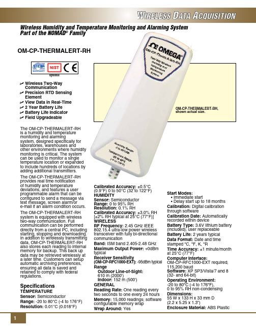
Dimensions: 55 W x 133 H x 33 mm D (2.2 x 5.25 x 1.3")
Enclosure Material: ABS Plastic
To Order
Model No.
Description
OM-CP-THERMALERT-RH
Wireless humidity and temperature transmitter
OM-CP-THERMALERT-RH-CERT Wireless humidity and temperature transmitter with NIST calibration certificate
Ordering Example: OM-CP-THERMALERT-RH-CERT, wireless humidity and temperature transmitter with NIST calibration certificate and OM-CP-RFC1000-EXT, wireless transceiver package.
OM-CP-RFC1000-IP69K Splash proof (IP69K) wireless transceiver package includes RF transceiver, USB cable, Windows software and operator’s manual (not CE approved)
Specifications
Temperature
Sensor: Semiconductor
湿度与温度传感器数据表说明书

• Measuring range from 5 to95% RH and from 0 to 50 °C(1)or from -20 to 80 °C(2)• 0-10 V output, active, powersupply 24 Vac/Vdc (3-4 wires)or 4-20 mA output, passive loop,power supply from 16 to 30 Vdc(2 wires)• ABS V0 housing IP65(2) or IP20(1),with or without display• Alternating display of humidity andtemperature• “¼ turn” system mounting withwall-mount plate• Housing with simplified mountingsystemFeatures of housingPart numberPower supply / OutputA: Active 24 Vac/Vdc – 0-10 VP: Passive – 16/30 Vac - 4-20 mADisplayO: With displayN: Without displayType of probeS: AmbientA: DuctD: RemoteExample: TH 110 – ANSHumidity and temperature transmitter TH 110,0-10 V active, without display, ambient model.(1) Ambient model / (2) Duct and remote modelDuct model, stainless steel probeProbe cable length (remote models only)( ): cable lentgh 2 m (standard model)05M: cable length 5 m10M: cable length 10 mTechnical specificationsConnectionsInside the front housing 1. Actif switch (S1)2. Inactive switch3. LCC-S software connection4. Output terminal block5. Power supply terminal block6.Cable glandSimplified calibrationElectronic board and measuring element connected to the front side of the sensor, which allows toconfigure and calibrate your device without causing any damage.12Removable front faceFixed back housing6543General features*Can be configured by switch.**All the accuracy indicated in this technical datasheet were stated in laboratory conditions, and can be guaranteed for measurements carried out in the same conditions, or carried out with calibration compensation.Electrical connections NFC15-100This connection must be made by a qualified and trained technician. To make the connection, the transmittermust not be energized.For TH 110-AOS, TH 110-ANS, TH 110-AOD, TH 110-AND,TH 110-AOA, TH 110-ANA models with 0-10 V output – active:For TH 110-POS, TH 110-PNS, TH 110-POD, TH 110-PND, TH 110-POA, TH 110-PNA models with 4-20 mA output – passive:To make a 3-wire connection, before powering up the transmitter, please connect the output ground to theinput ground. See drawing below.IRH VdcIT Vdc IRH VdcIT Vdc VT GND VRH VT GND VRH1 2 3 4 56 7 + - +- +1 2 3 4 5 6 7- +- +or IRH VdcIT Vdc 1 2 3 4 5 6 7- +- +IRH VdcIT Vdc 2 wiresSymbols usedFor your safety and in order to avoid any damage of the device, please follow the procedure described in this document and read carefully the notes preceded by the following symbol:The following symbol will also be used in this document, please read carefully the information notes indicated after this symbol:VT GND VRH+-IRH Vdc IT Vdc IRH Vdc IT VdcF T _E N – T H 110 – 15/01/2021– N o n-c o n t r a c t u a l d o c u m e n t – W e r e s e r v e t h e r i g h t t o m o d i f y t h e c h a r a c t e r i s t i c s o f o u r p r o d u c t s w i t h o u t p r i o r n o t i c e .Only the accessories supplied with the device must be used.T o configure the transmitter , it must not be energized. Then, you can make the settings required, with the DIP switches (as shown on the drawing below). When the transmitter is configured, you can power it up.Please follow carefully the combinations beside with the DIP switch. If the combination is wrongly done, the following message will appear on the display of the transmitter “CONF ERROR”. In that case, you will have to unplug the transmitter , place the DIP switches correctly, and then power the transmitter up.1234Off OnActive switchUnit settingOutput setting On-off switch1234Active switch (S1)Please refer to the user manual of the LCC-S software to make the configuration.Set the DIP switches as shown beside.Connect the cable of the LCC-S to the connection of the transmitter.PC configurationSettings and use of the transmitterIt is possible to set the measuring ranges and the unit of the instrument either by switch and/or via software.ConfigurationAmbient model does not have any mounting plate. 4 fixing holes are present inside the back housing. Use them to install the transmitter on the required location.Configuration via LCC-S software (option)It is possible to configure intermediate ranges, an offset...Example: for a 0-100 °C transmitter, minimum delta minimum is 20 °C. The instrument can be configured from 0 to +20 °C or from -10 to +10 °C. In order to compensate a possible drift of the sensor, it is possible to add an offset to the displayed value by the TH110 transmitter: it shows 48% RH, a standard instrument shows 45% RH. It is then possible, via the software, to integrate an offset of -3 to the displayed value by the TH 110 instrument. The configuration of the parameters can be done either with the DIP switch or via software (you can not combine both solutions).Maintenance:• Avoid any aggressive solvent.• Protect the transmitter and its probes from any cleaning product containing formalin, that may be used for cleaning rooms or ducts.Precautions for use: always use the device in accordancewith its intended use and within parameters described in the technical features in order not to compromise the protection ensured by the device.WarrantyInstruments have 1-year guarantee for any manufacturing defect.。
湿度传感器产品说明书.pdf_1718742584.1268241
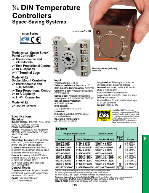
P-26To order, specify model number and range (from chart above.) To order 230V, add “-230V” to model number, no additional cost.Ordering Examples: 6132H-J-0-300C-230V, on/off controller with socket mounting and230 Vac power. OCW-2, extends standard 3-year warranty to a total of 5 years. 6102J-0-1000F proportional controller with socket mounting.Specifications Electrical Supply Voltage: 115 Vac (-15%, 20%), 50/60 Hz (optional) 230 Vac Power Consumption: 2 VAOutput: 10 A relay, SPST with power internally wired to contacts; 5 A relay, SPDT for 6132H Control Calibration Accuracy: ±2% of scale span or 4°C, whichever is greater (from 10 to 90% of scale span)Linearity-Resolution: Linearity 6%, resolution 1% maximum of scale span (dependent on sensor/range)Control Accuracy: ±0.4% FS at anambient of 22°C (72°F); ±2°C (3.6°F), at rated line voltage, after 30 minutes setting time; cycle time: 25 s, approximately Control Modes Time Proportional: Proportional with accelerated response to temperature variations; 3.5% band On/Off: Model 6132H only; 4°C (7°F) differentialModel 6103 “Space Saver” Panel ControllerU T hermocouple andRTD Models U T ime-Proportional Control U 10 A Capacity U 1⁄4" Terminal LugsInput Thermocouple:J, K, S External resistance: Maximum 100 ΩCold-Junction Compensation: AutomaticCommon Mode: Negligible effect up to 270V 50/60 Hz Series Mode: Negligible effect up to scale spread mV equivalent at 50/60 Hz Sensor Break Protection: Automatic upscale RTD Sensor: 100 Ω platinum a =0.00385General Indication: A high-brightness LED shows heat is on Operating Temperature: 0 to 50°C (32 to 122°F) Suppression: Filtering is provided for line and sensor input interference Dimensions:48 H x 48 W x 98 mm D(1.89 x 1.89 x 3.86")Construction:Flame-retardantpolycarbonate and ABS; bezel and knob coated with Nextel ®Connections: 1⁄4" standard terminal lugs or 11-pin connector Weight: 200 g (7 oz)Model 6102Socket Mount Controller U T hermocouple and RTD Models U T ime-Proportional Control U 10 A Capacity U 11-Pin Connector Model 6132U O n/Off Control 6102-J-0-300F 1⁄16 DIN.1⁄16 DIN Temperature Controllers Space-Saving SystemsOMEGACARE SMextendedwarranty program is available for models shown on this page. Ask your sales representative for full details when placing an order. OMEGACARE SMcovers parts,labor and equivalent loaners.Mounting bracket (included), actual size.。
温湿度传感器产品说明书 ZZ-THS-ST
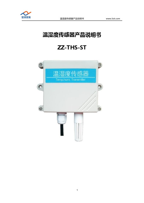
温湿度传感器产品说明书ZZ-THS-ST目录温湿度传感器产品说明书 (1)ZZ-THS-ST (1)1.产品简介 (3)1.1产品概述 (3)1.2功能特点 (3)2.参数详情 (4)2.1外形尺寸图 (4)2.2基本参数 (4)2.3模拟量参数含义 (5)2.3.1模拟量4-20mA电流输出 (5)2.3.2模拟量0-10V电压输出 (5)2.3.3模拟量0-5V电压输出 (6)2.4通讯协议 (6)2.4.1通讯基本参数 (6)2.4.2数据帧格式定义 (7)2.4.3寄存器地址 (9)2.4.4通讯协议示例以及解释 (9)3.安装使用 (11)3.1系统架构图 (12)3.1.1直接接电脑或者PLC (12)3.1.2网络传输使用 (13)3.2接口说明 (13)3.3接线说明 (14)3.3.1典型四线制接线方式 (14)3.3.2典型三线制接线方式 (16)3.4协议调试(只适用于485输出型) (17)4.包装售后 (21)4.1产品包装清单 (21)4.2联系方式 (21)4.3质保与售后 (21)4.4免责声明 (22)1.产品简介1.1产品概述该变送器广泛适用于农业大棚/花卉培养等需要温湿度监测的场合。
传感器内输入电源,感应探头,信号输出三部分完全隔离。
安全可靠,外观美观,安装方便。
1.2功能特点●探头灵敏度高●信号稳定,精度高●测量范围宽、线形度好●防水性能好、使用方便●便于安装、传输距离远等2.参数详情2.1外形尺寸图2.2基本参数参数技术指标温度测量范围-40℃-80℃(可定制)湿度测量范围0-100%RH温度测量精度±0.5℃(25℃典型值)湿度测量精度±3%RH(5%RH-95%RH,25℃典型值)(1)温度长期稳定性≤0.1℃/y温度长期稳定性≤1%/y通讯端口RS485Modbus协议/模拟量接口(电压型或者电流型)供电电源12V-24V DC最大功耗≤0.3W(@12V DC,25℃)外形尺寸110×85×44mm3电流输出类型4-20mA电流输出负载≤600欧姆电压输出类型0-5V/0-10V电压输出负载≤250欧姆工作压力范围0.9-1.1atm2.3模拟量参数含义2.3.1模拟量4-20mA电流输出电流值温度湿度4mA-45℃0%20mA115℃100%计算公式为P=(I-4mA)*6.25%其中I的单位为mA。
室内温湿度记录仪技术说明
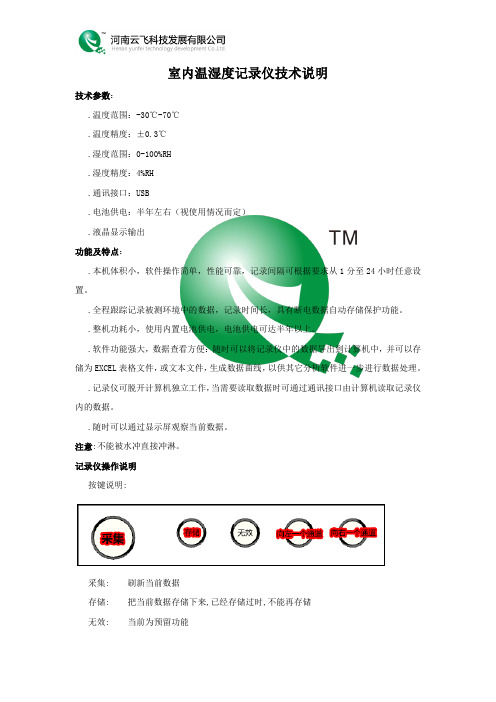
室内温湿度记录仪技术说明技术参数:.温度范围:-30℃-70℃.温度精度:±0.3℃.湿度范围:0-100%RH.湿度精度:4%RH.通讯接口:USB.电池供电:半年左右(视使用情况而定).液晶显示输出功能及特点:.本机体积小,软件操作简单,性能可靠,记录间隔可根据要求从1分至24小时任意设置。
.全程跟踪记录被测环境中的数据,记录时间长,具有断电数据自动存储保护功能。
.整机功耗小,使用内置电池供电,电池供电可达半年以上。
.软件功能强大,数据查看方便:随时可以将记录仪中的数据导出到计算机中,并可以存储为EXCEL表格文件,或文本文件,生成数据曲线,以供其它分析软件进一步进行数据处理。
.记录仪可脱开计算机独立工作,当需要读取数据时可通过通讯接口由计算机读取记录仪内的数据。
.随时可以通过显示屏观察当前数据。
注意:不能被水冲直接冲淋。
记录仪操作说明按键说明:采集: 刷新当前数据存储: 把当前数据存储下来,已经存储过时,不能再存储无效: 当前为预留功能向左一个通道: 查看左面一个通道,当通道为第一通道时,将不会再向左向右一个通道查看:右面一个通道,当通道为最后通道时,将不会再向右屏幕显示说明:空温: 当前显示的为空气温度数据空湿: 当前显示的是空气湿度数据充电说明在不连接USB数据线的情况下,设备中的指示灯为灭状态,当连接上USB数据线时,设备将自动进入充电状态,指示灯显示为红色,充满电时显示为绿色通讯线与记录仪的连接1.打开安装光盘下的<其它程序>目录,安装其中的USB数据线驱动2.取出随机附送的USB数据连接线,两端分别接入电脑及设备后,电脑会提示找到新硬件,并自动安装驱动。
3.打开记录仪软件,选择USB通讯线的端口,或选择自动选择端口,进行记录仪与电脑的连接。
4.连接上后,上位机的软件会进入主界面,具体操作请查看软件使用说明书。
5.如果连接不上,请检查电脑与记录仪之间的连接线是否有问题。
湿度温度传感器系统说明书

Mounting Cont'd.DIN Rail Mounting Bracket InstallationInput ConnectionThe UWRH can provide fast, accurate readings from aHumidity Probe with a M12 8 pin connector.Input Diagram for M12 8-pin ConnectorBattery ReplacementTo install or replace the battery in your device you must first loosen the one screw located on the lid of the enclosure. This will allow you to access the battery compartment.Your device is equipped with a “C” size lithium power cell assembly. To install a replacement battery assembly follow steps outlined here.A. Remove the old power cell from the battery holder.B. I nstall your new battery assembly into the housing in the same position as the old battery was located.C. Installation complete.WGS/START HERE ARRO 5WGS/START HERE ARRO6UWRH-2A-NEMA-M12, UWRH-2A-NEMA-M12-CABLE,Weather Resistant Wireless Relative Humidity/Temperature TransmitterMQS5044A-RH/0913System OperationA basic wireless RH system is comprised of only two main components; a signal conditioner with a built-in battery powered 2.4 GHz radio transmitter (End Device), and a USB powered 2.4 GHz radio receiver.End Device/ReceiverTransmit Rate vs. Battery LifeMany factors such as ambient temperature conditions and transmitting rate can have a large effect on the life of the battery used in your end device. Transmitting data places a large demand on the battery in your unit. The transmit rate is the single most contributing factor in the life of your battery. The slower the transmit rate you set, the longer the battery in your device will last. The table below gives some estimates on how long the battery should last vs. the transmit rate you selected when you setup your end device and under normal operating conditions. Transmission IntervalBattery Life (Months)2 Seconds 4 10 Seconds 7.5 30 Seconds 16.560 Seconds30SpecificationsTemperature Range: -17 to 49°C (2 to 120°F)/manuals/manualpdf/M5044-RH.pdf***********************®It is the policy of OMEGA Engineering, Inc. to comply with all worldwide safety and EMC/EMI regulations that apply. OMEGA is constantly pursuing certification of its products to the European New Approach Directives. OMEGA will add the CE mark to every appropriate device upon certification.The information contained in this document is believed to be correct, but OMEGA accepts no liability for any errors it contains, and reserves the right to alter specifications without notice.WARNING: These products are not designed for use in, and should not be used for, human applications.WARRANTY/DISCLAIMEROMEGA ENGINEERING, INC. warrants this unit to be free of defects in materials and workmanship for a period of 13 months from date of purchase. OMEGA’s WARRANTY adds an additional one (1) month grace period to the normal one (1) year product warranty to cover handling and shipping time. This ensures that OMEGA’s customers receive maximum coverage on each product.If the unit malfunctions, it must be returned to the factory for evaluation. OMEGA’s Customer Service Department will issue an Authorized Return (AR) number immediately upon phone or written request. U pon examination by OMEGA, if the unit is found to be defective, it will be repaired or replaced at no charge. OMEGA’s WARRANTY does not apply to defects resulting from any action of the purchaser, including but not limited to mishandling, improper interfacing, operation outside of design limits, improper repair, or unauthorized modification. This WARRANTY is VOID if the unit shows evidence of having been tampered with or shows evidence of having been damaged as a result of excessive corrosion; or current, heat, moisture or vibration; improper specification; misapplication; misuse or other operating conditions outside of OMEGA’s control. Components in which wear is not warranted, include but are not limited to contact points, fuses, and triacs.OMEGA is pleased to offer suggestions on the use of its various products. However, OMEGA neither assumes responsibility for any omissions or errors nor assumes liability for any damages that result from the use if its products in accordance with information provided by OMEGA, either verbal or written. OMEGA warrants only that the parts manufactured by the company will be as specified and free of defects. OMEGA MAKES NO OTHER WARRANTIES OR REPRESENTATIONS OF ANY KIND WHATSOEVER, EXPRESSED OR IMPLIED, EXCEPT THAT OF TITLE, AND ALL IMPLIED WARRANTIES INCLUDING ANY W ARRANTY OF MERCHANTABILITY AND FITNESS FOR A PARTICULAR PURPOSE ARE HEREBY DISCLAIMED. LIMITATION OF LIABILITY: The remedies of purchaser set forth herein are exclusive, and the total liability of OMEGA with respect to this order, whether based on contract, warranty, negligence, indemnification, strict liability or otherwise, shall not exceed the purchase price of the component upon which liability is based. In no event shall OMEGA be liable for consequential, incidental or special damages.CONDITIONS: Equipment sold by OMEGA is not intended to be used, nor shall it be used: (1) as a “Basic Component” under 10 CFR 21 (NRC), used in or with any nuclear installation or activity; or (2) in medical applications or used on humans. Should any Product(s) be used in or with any nuclear installation or activity, medical application, used on humans, or misused in any way, OMEGA assumes no responsibility as set forth in our basic WARRANTY/DISCLAIMER language, and, additionally, purchaser will indemnify OMEGA and hold OMEGA harmless from any liability or damage whatsoever arising out of the use of the Product(s) in such a manner.RETURN REQUESTS/INQUIRIESDirect all warranty and repair requests/inquiries to the OMEGA Customer Service Department. BEFORE RETU RNING ANY PRODU CT(S) TO OMEGA, PU RCHASER MU ST OBTAIN AN AUTHORIZED RETURN (AR) NUMBER FROM OMEGA’S CUSTOMER SERVICE DEPARTMENT (IN ORDER TO AVOID PROCESSING DELAYS). The assigned AR number should then be marked on the outside of the return package and on any correspondence.FOR WARRANTY RETURNS,please have the followinginformation available BEFOREcontacting OMEGA:1. Purchase Order number underwhich the product was P U RCHASED, 2. Model and serial number of the product under warranty, and 3. Repair instructions and/orspecific problems relative tothe product.FOR NON-WARRANTY REPAIRS, consult OMEGA for current repair charges. Have the following information available BEFORE contacting OMEGA:1. Purchase Order number tocover the COST of the repair or calibration,2. Model and serial number of theproduct, and 3. R epair instructions and/or specific problems relative to the product.OMEGA’s policy is to make running changes, not model changes,whenever an improvement is possible. This affords our customers the latest in technology and engineering.OMEGA is a registered trademark of OMEGA ENGINEERING, INC.© Copyright 2013 OMEGA ENGINEERING, INC. All rights reserved. This document may not be copied, photocopied, reproduced, translated, or reduced to any electronic medium or machine-readable form, in whole or in part, without the prior written consent of OMEGA ENGINEERING, INC.Patented: Covered by U.S. and International Patents and Patents Pending.The “Welcome to the TC Central Setup Wizard” screen should be visible on your computer screen. The installer will guide you through the steps required to install TC Central on your computer.Device ConfigurationFirst, connect the provided USB cable to yourconnector/transmitter unit and also to an available USB port on your computer.Now that you have connected your USB cable to your PC and transmitter you will complete the following steps to configure your device beforeplacing the unit into operation. You will be using the configuration software utility (TC Central>>End Device Configuration Wizard) that you installed onto your PC in the previous section. If you have not installed the configuration software utility you should do so now. During this procedure you will be setting the following parameters in your transmitter.Button Operation 1. “ON/OFF”The “ON/OFF” button on the front of your connector/transmitter is used to turn your unit “ON” or “OFF”.2. “SETUP”The “SETUP” button on the front of your connector/transmitter is only used during the setup and configuration of your unit.Indicator Lights1. Transmit (TX) Green Indicator LightThe green indicator light marked “TX” on the front of your connector/transmitter will blink every time the unit sends data to the receiving unit. Example: If you selected a 5 second sample rate the green TX LED will blink one time every 5 seconds.2. Low Battery (Low Bat) Red Indicator LightThe red indicator light marked “Low Bat” on the front of the connector/transmitter will turn on when the battery reaches a level at or below the power level required for normal operation. When this indicator turns on it’s time to install a fresh battery in your unit. For procedures on how to change your battery see the later section Battery ReplacementChannel NumberThis sets a unique address number into yourtransmitter. Later, when you set up your measurement software you will again set channel numbers to receive readings from the corresponding unit(s). Each unit must be set for a different channel number for your system tooperate correctly.WGS/START HERE ARROWGS/START HERE ARRO 2WGS/START HERE ARRO34Using This Quick Start Manual Use this Quick Start Manual with your UWRH-2A-NEMA –M12 Weather Resistant Wireless Relative Humidity/Temperature Transmitter for quick installation and basicoperation. For detailed information, refer to the User’s Guide (Manual # M5044)General DescriptionThe UWRH-2A-NEMA-12 and UWRH-NEMA-M12-CABLE Weather Resistant Wireless Relative Humidity/Temperature Transmitter feature a standalone, compact, battery powered NEMA rated design that transmits measurements back to a host receiver up to 120m (400’) away. When activated the wireless transmitter will transmit readings continuously at a pre-set time interval that was programmed by the user during initial setup. Each unit measures and transmits: Relative Humidity Reading, Ambient Temperature, RF Signal Strength and Battery Condition to thereceiver and is displayed on your PC in real time using the provided software.Main Transmitter BoardSoftware InstallationSystem Minimum Requirements:• Pentium Class processor • Hard Drive Space: 210 MB • RAM: 256 MB • 1 Available USB Port • 1 CD-ROM Drive• Windows 2000, XP , Vista, 7Insert the TC-Central User CD that was included with your receiver unit into the CD-ROM drive of your PC. Your system should begin the installation process Sample Rate:This will program your device to transmit 1 data reading to your receiver at a specified time interval. Available settings are 2, 3, 5, 15, 30, 45, 60, 75 or 90.STEP 1. Enter the “SETUP” mode.To place your transmitter into the “SETUP” mode for programming follow this procedure:Press and hold the “ON/OFF” button. While the “ON/OFF” button is being held, press the “SETUP” button one time and then release the “ON/OFF” button. The green (TX) indicator on the front of your device should be blinking at a steady rate. This indicates that your device is ready to run the configuration utility software.(Refer to Main Transmitter Board diagram for button locations)STEP 2. Launch Setup Utility Program.To launch the End Device Configuration Wizard, begin by accessing the “Programs” list under your “Start Menu”.Scroll through the list to find the Omega “TC-Central” folder, and then select the End Device Configuration Wizard.STEP 3. Programming the device settings .After starting the setup utility program, the ”Welcome to the Universal Wireless End Device Configuration Wizard” screen should be visible on your screen. The software will guide you through the steps required to program your device settings.Device InstallationWhen installing your device it is important to position your device in such a way as to optimize the antenna location within what is known as the “Fresnel Zone”.The Fresnel Zone can be thought of as a football-shaped invisible tunnel between two locations that provides a path for RF signals between your deviceIn order to achieve maximum range, the football-shaped path in which radio waves travel must be free of all obstructions. Obstacles in the path (especiallymetal) will decrease the communication rangebetween your device and your receiver. Also, if the antennas are mounted just barely off the ground, over half of the Fresnel zone ends up being obstructed by the earth resulting in significant reduction in range. To avoid this problem, the antennas should be mounted high enough off of the ground so that the earth does not interfere with is allowed. By definition co-location is when another radio device or the device's antenna is located within 20 cm of your connector/transmitter and can transmit simultaneously with your unit.MountingWhen mounting your end device, care should be taken to make sure it is as far away from any metal objects. If nearby metal gets too close to your unit, it has the potential to interfere with the way the unit radiates and may cause signal loss or possibly even the inability to communicate at all with yourTo install the DIN Rail Mounting Bracket accessory (UWM-DINRAIL) you must first remove the one screw located on the lid of the enclosure. This will allow you access to the mounting holes.Place all four #4-40 screws with threaded standoffs into each mounting hole. Screw on the DIN Rail Mounting Bracket sub assembly including the DIN Rail Adaptors to the bottom of the enclosure using the #4-40 screws.Close the unit by threading the one screw located on the lid of the enclosure to the bottom enclosure.。
温湿度传感器使用说明书

NO:S1*******使用说明书温湿度传感器目录1、产品介绍 (1)1.1概述 (1)1.2功能特点 (1)1.3外观尺寸 (1)2、性能参数 (2)3、使用方法 (4)3.1系统框架图 (4)3.2安装说明 (6)4、通信协议 (9)4.1通讯基本参数 (9)4.2数据帧格式定义 (9)4.3通讯基本参数 (11)4.4通讯协议示例以及解释 (12)5、常见问题及解决方法 (14)6、保养维护 (15)7、运输存储 (16)7.1运输要求 (16)7.2存储要求 (16)8、订货服务 (17)8.1订货方法 (17)8.2客户服务 (17)1产品介绍1.1概述本(系列)产品可在线监测环境温度和湿度信息,广泛用于开关柜仪表室、断路器室、电缆室等处的环境温湿度在线监测。
采用进口工业级微处理器芯片、进口高精度温度传感器,确保产品高精度和可靠性。
1.2功能特点◆进口的测量单元,测量精准。
◆专用的485电路,通信稳定。
◆宽电压范围供电,安装方便。
1.3外观尺寸(单位:mm公差:±0.5)2性能参数3使用方法3.1系统框架图本产品也可以多个传感器组合在一条485总线使用,理论上一条总线可以接254个485传感器,另一端接入带有485接口的PLC 、通过485接口芯片连接单片机,或者使用USB转485即可与电脑连接,使用我公司提供的传感器配置工具进行配置和测试(在使用该配置软件时只能接一台设备)。
3.2安装说明3.2.1注意事项1、传感器应尽量垂直放置,保证安装墙面时,温湿度探头在传感器本体的下方(传感器本体上的字体为正方向)。
2、安装高度为人体坐高或主要测量的环境区域。
3、避免在易于传热且会直接造成与待测区域产生温差的地带安装,否则会造成温湿度测量不准确。
4、安装在环境稳定的区域,避免直接光照,远离窗口及空调、暖气等设备,避免直对窗口、房门。
5、尽量远离大功率干扰设备,以免造成测量不准确,如变频器/电机等。
湿度传感器产品说明书.pdf_1719189628.4718778

2223 24 252627283634 24 31 323319Item Part Name Model8-025Model8-050Model8-075Model8-150Qty1 Pulley 602 602 727 1563 22 Frame 708303 708462 408452 408315 13 3/8-16x8 ½ Hex Cap Screw 433420 43342 N/A N/A 2 3 ½-13X10” Hex Cap Screw N/A N/A 43361 N/A 43 ¾-10X14” Hex Cap Screw N/A N/A N/A 43720 44 Name Plate 81002 81002 81002 2252 15 6-32x1/4” Self Tapping Screw 43876 43876 43876 43876 46 Table Plate 545 545 702 1534 27 V- Block 336 336 336 1576 28 Table Spacer 716692 568 716 1553 49 Table Channel 4100 4100 2243 4207 210 5/8” Lockwasher 43648 43648 43648 N/A 410 ¾” Lockwasher N/A N/A N/A 43649 411 5/8-11 HEX Nut 43917 43917 43917 N/A 411 ¾-10 Hex Nut N/A N/A N/A 43919 412 Table Pin 2256 2256 2256 N/A 412 Table Pin N/A N/A N/A 1555 613 Base Angle 566 566 566 1551 214 ½-13X1-1/4” Hex Cap Screw 43348 - 43349 1551 4 14 ½-13X1-1/2” Hex Cap Screw 4334914 5/8-11X1 ¾ Hex Cap Screw N/A N/A N/A 43365 415 ½” Lockwasher 43647 43647 43647 N/A 415 5/8 Lockwasher N/A 43648 N/A 43648 416 ½-13 Hex Nut 43916 43916 43916 N/A 416 5/8-11 Hex Nut N/A 43917 N/A 43917 417 Cable 580 580 580 1562 118 Cable Clamp 991 991 583 583 422 Hand Crank Assembly 701653 701653 701653 701653 123 Worm Shaft 384 7530 384 742 125 Worm Key 386 386 386 746 126 Worm 385 385 385 744 127 Hoist Frame 725 725 725 739 128 3/8-16x2 ½ Hex Cap Screw 43335 43335 43335 N/A28 3/8-16X2-3/4” Hex Cap Screw 43335 43335 43335 43353 2 30 3/8-16 Hex Nut 43912 43912 43912 N/A 230 ½-13 Hex Nut N/A N/A N/A 4391631 Drum Shaft 724 724 724 741 132 Drum Key 737 737 737 745 133 Worm Gear 736 736 736 743 134 Cable Drum 723 723 723 740 135 Retaining Ring 43983 43983 43983 -36 Retaining Ring - - - 4398236 Grooved Pin - - - 4406237 Tube Elbow 1252 1252 1252 1944 138 Bushing 1657 1657 1657 N/A 139 Wear Ring 37036 37041 37046 37051 240 T-Ring 17976 17878 17942 37052 141 Piston 35811 35563 35575 35585 142 Cylinder 34321 35561 35589 35584 143 O-Ring 29637 29638 37048 25823 144 T-Ring 37037 37044 36311 37054 145 Wear Ring 37038 37045 37050 37055 1or246 Oil Seal 944 1477 1357 1524 147 PistonGuide 34322 35562 35573 35592 148 Tube Valve to bot. cyl. - - - - 149 Tube valve to top cyl - - - - 150 Straight fitting 17920 17920 17920 17920 3Figure 151 Back up washer 37040 37043 37049 37053 152 Manual 4 way valve 29662 29662 29662 29662 153 Tube Valve to gauge - - - - 154 Panel decal 36590 36590 36590 36590 155 Gauge 71270 71271 71272 71273 156 10-24x2-3/4” mach. Flat hd. Screw 300248 300248 43821 43821 457 Control Panel 81395 813958139581395 158 Tube pump to valve - - - - 159 Tube valve to reservoir - - - - 160 Tube reservoir to pump - - - - 161 Tube elbow62 Tube elbow63 ½-13x1 Socket Hd Cap screw 43469 43347 43469 - 463 ½-13x1 ¼ 43470 43470 43470 43470 464 ½” Lockwasher 43647 43647 43647 - 465 ½-13x3/4 43345 43345 43345 - 466 10-24x3/8 Pan hd. Screw 43881 43881 43881 - 467 5/16-18x1 Hex Cap Screw 43315 43315 43315 - 468 5/16” Lockwasher 43644 43644 43644 - 469 5/16-18x3/4 Hex Cap Screw 43314 43314 43314 - 469 3/8-16x1 Hex Cap Screw - - - 43328 470 Pump 301756 301756 301756 29608 171 Pump Support 25916 25916 25916 36299 172 Coupling Guard 36761 36761 36761 - 173 Motor - 29744 - - 174 Coupling 28498 28498 28498 - 1Coupling Half - - - 29556 1 Coupling Half - - - 29557 1 Spider - - - 29942 175 Adapter Flange 1067 1181 1400 2029 176 Nose Piece 942 1150 3276 1987 177 Pump & Motor Base 36509A 36509A 36509A - 178 3/8-16 Nut hex 43912 43912 43912 - 479 3/8 Lockwashers 43645 43645 43645 - 480 Washers 2248 2248 2248 - 481 Reservoir 36510 36510 36510 36527 182 ¼ Soc pipe plug 1567 1567 1567 1567 183 ¾ Soc pipe plug 1745 1745 1745 1745 184 Breather Filter 29571 29571 29571 29571 185 Straight Fitting 17920 17920 17920 1943 186 3/4x1/2 Reducer - - - 1153 287 Tube Elbow 1252 1252 1252 17974 188 5/16 Lockwashers 43644 43644 43644 - 488 3/8 Lockwashers - - - 43645 489 1/8 Soc pipe plug 589 589 589 589 190 Repair Kit items 39, 40, 43, 44, 45,46, 51711016 711017 711018 711019N/A Table Hoist Assembly items22,23,24,25,26,27,31,32,33,34700112-S 700112-S 1Work head exploded viewItemPart NameModel 25 tonModel 50 tonModel 75 tonModel 150 tonQtyN Adaptor Flange 1067 1181 1400 2029 1 M Nose Piece 942 1150 3276 1987 1 L Piston 35811 35563 35575 35585 1 K Oil Seal 944 1477 1357 1524 1 J Piston Guide 34322 35562 35573 35592 1 H Teflon wear ring 37038 37045 37050 37055 2 G Palmetto ring 37037 37044 36311 37054 1 F Cylinder flange 86610 35565 35593 83880 1 E Back-up washer37040 37043 37049 37053 1 D O-ring29637 37048 25823 1 C Teflon wear ring 37036 37041 37046 37051 2 B Palmetto Ring 17976 17878 17942 37052 1 A Cylinder34321 35561 35589 35584 1 N/A Complete assembly7077257080777080557080781 Repair Kit items C, B, D, G, H, K, E 711016 711017 711018 711019Items 19,22,23,24 torque to 85 In lbsItem Part Name Part numberQty2-6 Pressure head repair kit one each of 2-6 54165 1 13 Grommet 47298 1 39 Handle 301328 1 41 Saddle 301329 1 48 Dual valve operating lever 301330 1* Kit Valve segment unit repair kit, includes one each of items 25and 30 thru 34, two each of items 14, 16, 18, 24, 26 and 28,four each of 15 thru 17, 6 each of 1367741 1 or 2**Kit Segment replacement, includes one each of 19 thru 23, 25, 27,30 thru 34, 41, 44 and 45, two each of 14, 16, 18, 24, 26, 28,29, 37, 38, 42 and 43.301735*Note: 1 pc. For a 3 way valve (new 3way valve part number is 29661) These Dynex valves have all ½” NPT port sizes2 pc. For 4 way valve (new 4 way valve part number is 29662)** Note: This kit is completely assembled and pre tested and ready for service.29662 Dynex valve replaces the Dake valve 26-300 and 26-302. Repair kit for the 26-300 is part number 710146. No repair kit available for the 26-302.29661 Dynex valve replaces the Dake valve 26-301. Repair kit for the 26-301 is part number 710146.Note: If replacing a Dake valve with a Dynex valve, the port location may be different than the Dake valve.THIS DIAGRAM IS FOR THE 25, 50 AND 75 TON MODELSONLYD# 33720Electrical parts listPart # Part description Qty302062 Starter enclosure 129796 Switch manual 1302187 Motor starter 220 volt 1Motor starter 440 volt 166244 Heater overload (150ton only) 3150 ton model onlyD# 81020Part Name25 ton50 ton75 ton150 tonQty1 Reservoir36510 36510 36510 36527 1 1 Reservoir filter breather 29571 29571 29571 29571 2 Motor – electric 301382 301382 301382 70901 1 3 Pump301756 301756 301756 29608 1 4 4 way valve w/relief valve 29662 29662 29662 29662 1 5 Work Head 707725 713717 708055 708078 1 6 Gauge71270 71271 71272 71273 1 N/A Cylinder bore 3 5/8” 5” 6” 8” N/A N/A Rod diameter 2 ¾” 4” 4 ¾” 6” N/A N/A Stroke 10” 10” 10” 16” N/A N/A PSI4845 5100 5305 5970 N/A N/A Piston Thread diameter ACME1 ½ - 62 – 62 ½ - 43 ½ - 4N/A724 Robbins RoadGrand Haven, MI 49417Phone: 616-842-7110 800-937-3253 Fax: 616-842-0859 800-846-3253 Web: E-mail: **************************** *****************************。
温湿度传感器使用说明书
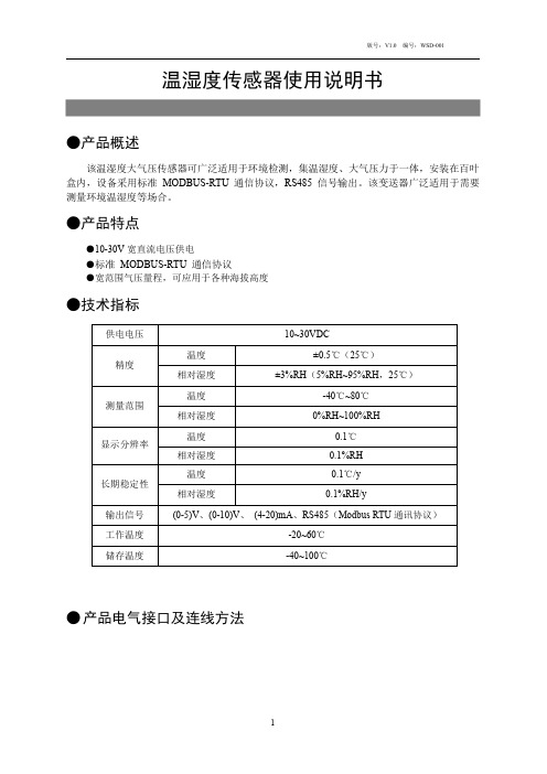
温湿度传感器使用说明书●产品概述该温湿度大气压传感器可广泛适用于环境检测,集温湿度、大气压力于一体,安装在百叶盒内,设备采用标准MODBUS-RTU通信协议,RS485信号输出。
该变送器广泛适用于需要测量环境温湿度等场合。
●产品特点●10-30V宽直流电压供电●标准MODBUS-RTU通信协议●宽范围气压量程,可应用于各种海拔高度●技术指标供电电压10~30VDC温度±0.5℃(25℃)精度相对湿度±3%RH(5%RH~95%RH,25℃)温度-40℃~80℃测量范围相对湿度0%RH~100%RH温度0.1℃显示分辨率相对湿度0.1%RH温度0.1℃/y长期稳定性相对湿度0.1%RH/y输出信号(0-5)V、(0-10)V、(4-20)mA、RS485(Modbus RTU通讯协议)工作温度-20~60℃储存温度-40~100℃●产品电气接口及连线方法数字RS485输出接线方式线色引线定义电源红色电源正(10~30V DC)黑色电源负通信绿色RS485-A 白色RS485-B模拟输出接线方式线色引线定义电源红色电源正(10~30V DC)黑色电源负通信绿色温度信号输出正白色温度信号输出负蓝色湿度信号输出正黄色湿度信号输出负注:接线方式以产品引线上说明为准●注意事项1打开产品包装后,请检查产品外观是否完好,核定产品使用说明书相关内容与产品是否一致,并妥善保管产品使用说明书一年以上;2严格按产品接线示意图接线,并在产品允许激励电压下工作,切勿过电压使用;3产品切莫敲打,以免损环外观和内部结构;4产品无客户自行维修部件,出现故障时请与我公司联系;5本公司产品正常情况下使用出现故障,保修期为一年(自我公司发货之日起至返回之日止13个月),是否属于正常情况下出现故障,以我公司质检员检测为依据。
超过期限维修,本公司收取成本费,本公司所有产品终身维修;6未尽之处,请查阅我公司网站或来电查询。
湿度传感器产品说明书
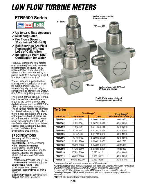
F-93U Up to 0.5% Rate Accuracy U 5000 psig Rated U F or Flows Down to 23 cc/min (0.006 GPM)U B all Bearings Are Field Replaceable Without Loss of Calibration U I ncludes 20-Point NIST Certification for WaterFTB9500 SeriesSPECIFICATIONSAccuracy: ±0.5% of reading with linearizationRepeatability: ±0.25% or reading Fluid Temperature Range: -268 to 232°C (-450 to 450°F)Materials of Construction: 304 SS housing, 440C SS ball bearings, 17.4 PH SS rotor, and FKM seals Weight:FTB9501 to FTB9508: 454 g (1 lb) FTB9509 to FTB9512: 907 g (2 lb)Connections: 1⁄2 MNPT std; 1⁄2" 37 degree flare optional Maximum Pressure Drop (at 1 CK): 10 psidMaximum Pressure: 5000 psig (std)Output: Non-linear sinewaveComes complete with operator’s manual and NIST certificate .* Approximate: 20-point calibration supplied with each unit. Calibrated for water. For fluids of different viscosities, please consult OMEGA’s Flow Engineering Department.For units with 37° Flare fittings, add suffix “-MS ” to model number, for additional cost.Ordering Examples: FTB9503-MS , flow meter with 40 to 700 cc/min range, and male 37° flare ports.FTB9510, flow meter with 275 to 5000 cc/min range.Models shown with NPT and 37° flare end fittingsModels shown smaller than actual size.For FLSC-64 series of signal conditioners, visit us online.Low FLow Turbine MeTersFTB9500 Series low flow meters offer extremely accurate low flow measurement of liquids. They utilize a Pelton wheel-like rotor whose motion is converted by a pickup coil into a frequency output that is proportional to flow.These units are supplied with a mating 2-wire connector and can be supplied with FLSC-60series integrally mounted signal conditioners to provide 4 to 20 mA, 0 to 5 V, or amplified pulse outputs.The output of the FTB9500 Series low flow meters is non-linear and requires the use of a linearizing digital indicator such as OMegA’s DPF-311-LIN Series indicators. These turbine meters are intended for clean fluid service only; where there is any doubt as to the purity of the process fluid, strainers are recommended. In addition, when using these units for fluids with viscosities other than 1 centistoke, special calibrations are available—consult OMegA’s Flow engineering Department.FTB9501FTB9507-MSFTB9512。
温湿度监测设备说明书

9LAN-based Temperature and Humidity Monitoring - Supports Simultaneous WiFi and HardwiredInterfaces 9-20°C to +60°C (-4°F to +140°F) Standard Temperature Measurement Range 910% to 90% Measurement Range with RH Sensor9Combined Temperature/Humidity or Temperature Only measurements on each of Four Ports 9-200°C to +200°C (-328°F to +392°F) Measurement Range with Optional Probe 9Built-in Web Server Accessible and Configurable via Any Standard Web Browser 9Programmable Alarm Limits Per Channel 9Real Time email Alerts9NTP Server Support for Accurate Time and Date Stamps 9Built-in Memory for Stand-alone Operation 9Server-based Real Time Graphical Display9Easy Access to XML Feed and Text File for Historical Data9Excel-compatible Format for Easy Analysis and Report Generation 9Administrative Access Protected by User Name Name and Password 9Optional NIST Calibration Available9Pre-drilled Flange Allows Mounting Temperature Alert to AnySurfaceTemperature AlertLAN-based Temperature and Humidity Data LoggerTemperature Alert is an affordable, local area network (LAN)-based device for real time monitoring of temperature, or temperature and humidity.Temperature Alert provides all the features you’d expect from much more costly solutions. It includes both a WiFi radio and a hard wired Ethernet interface to connect to your LAN. Once connected its built-in web server gives you access to all of the product’s features. You can set alarm levels on a channel-by-channel basis; program SMTP parameters to report real time alarms, data and status to any email address; retrieve a text file and XML feed for manual or programmatic access to historical data. Preference settings allow you to config -ure temperature reporting in °F or °C. Set your time zone to report time and date stamps in local time, and specify an NTP time server to keep Temperature Alert precisely synced to Internet-based time servers. Multiple Temperature Alerts may be deployed and individually named for your application (“Freezer Room”, “Archive Warehouse”, etc.), and access to them can be strictly controlled with user names and passwords. Full-featured LAN interface flexibility is built in, so Temperature Alert easily adapts to the most basic and most complex network configurations.Temperature Alert is provided with an AC adaptor power supply and one temperature probe, or a temperature and humidity probe (6 ft, 1.8 m) depending upon the model selected. A selection of optional temperature and humidity probe configurations is also available.Four LEDs for status indicationStatus - Single blink, normal operation Power - Reserved Warning - ReservedFailure - Single blink, no sensors detectedFull Email SupportSend alerts, status, complete data files, and daily high, low, and average readings to any email address. Features a quick configu-ration mode for any Google gmail account.Fast and Easy Setup With GmailDo the peculiarities of the SMTP elude you? Then use a free Google gmail account and Temperature Alert’s one button gmail configuration setup to send email to any email address. Just select “Gmail SMTP”, your gmail user name and password, and the email address where you’d like reports to be sent. It’s that easy. Support for Four SensorsMeasures temperature and/or humidity from each of four sensor ports to minimize deployment cost.Built-in Security EnhancementsAccess to Temperature Alert may be strictly controlled with a user name and password, and its built-in web server means that you access it using a standard web browser with no software installed on your computer. Supports SSL/TLS cryptographic protocols to provide communication security over the Internet. Operating System-independentSince Temperature Alert provides a built-in web server, it can be accessed from any computer running any operating system with any web browser.Graphical Waveform DisplayWhen accessed using any standard web browser, Temperature Alert’s home page features Flash-based graphics to convey histori-cal recorded data. The time frame may be compressed or expanded to display more or less time history as required.NTP Time Server SupportProvided that Temperature Alert has Internet access it can use NTP web-based network time protocol servers to automatically sync its clock to those web standards.Built-in Wireless and Hardwired Ethernet Inter-facesUse either or both depending upon your networking requirements. Flexible Naming OptionsEach Temperature Alert sensor port may be assigned a unique name to identify it in generated reports, and Temperature Alert mainframes also can be uniquely named to distinguish them from others when multiple units are deployed.Integral Mounting FlangeSecure Temperature Alert in any deployment orientation with the pre drilled mounting flange.Single Base StationTo Temp/RH Sensor 1To provided AC Adaptor **************Multiple Base StationsTo LAN or computerHard wiredEthernet Switch or WiFiUnit AUnit BUnit CTo Temp/RH Sensor 3To Temp/RH Sensor 4330-668-1444 5 Temperature Alert’s built-in web server gives you access to a multitude of powerful features, all from the convenience of your web browser, without any installed software, and regardless of computer operating system.Built-in SecurityTemperature Alert’s security features prevent unauthorized access by requiring a user name and password.Home Page Features Quick-look StatusCurrent temperatureand humidity.Real time trending Click and drag to show temperature and humidity at any time.Click feed andhistorical data links to download data in an ASCII format, or to access data programmatically.Click tabs to access other features and configuration items as needed.330-668-1444 7 Quick and Easy Email ConfigurationClick to have Temperature Alert automatically scan for available WiFi router, and then select the one you want.Full support for all networking protocols: Static, IP, DHCP, subnet masks, and more.It’s easy to test your configuration ... just click here.One click selects your gmail account as the email server to any email domain, or select a custom SMTP configuration.Specify an email address for daily status updates, which can be different fromalarm emails.Configure SNMP TrapsSNMP traps allow a base stationto proactively alert a LAN-based administrative computer to alarm conditions. This removes the need for the administrator to continuously poll the base station.SNMP settings are optional. PreferencesSpecify a unique name for the base stationto easily identify it in emails and status reports.Program the sample interval, from once perminute to one every9,999 minutes.Click to select if the base station sends email alerts via its WiFi or hard wired Ethernet link.Specify a password to control access to the basestation.Program the base station to report temperatures in °C or °F.Select whether the base station sendsan alert upon every sample interval while in an alarm state, or only once when it first occurs.Configure the current time and time zone, as well as Internet-based time servers that the Temperature Alert’s base station will use to keep its internal clock synchronized.. 8Email AlertsDaily Status EmailsTwo typical email alerts, one for temperature and another for humidity.Email routing was all handled via a free, standard gmail account (TempAlert) using Gmail’s SMTP server, which is a single click Temperature Alert configuration.Note that destination emails are not limited to gmail, since these were sent to sales@.Alternatively, a custom SMTP server may be configured.An example of the daily status report sent from the free gmail account. The base station is configured to send these once per day to the **************************.The report provides an overview of temperature and humidity activity, showingminimum, maximum, and average values.An attached text file provides 10 330-668-1444A typical text file attached to daily status emails, or accessible at any time via download directly from the base station provides all acquired temperature and humidity data. Time and date stamps are also provided for each sample.The file’s delimited format allows data to be easily imported to any presentation and analysis application, like Microsoft Excel.most popular is Microsoft Excel.DATAQ, the DATAQ logo and WinDaq are registered trademarks of DATAQ Instruments, Inc. All rights reserves. Copyright © DATAQ Instruments, Inc.The information on this data sheet is subject to change without notice.241 Springside Drive Akron, Ohio 44333Phone: 330-668-1444Fax: 330-666-5434Data Acquisition Product Links(click on text to jump to page)Data Acquisition | Data Logger。
湿度传感器产品说明书.pdf_1718756265.1307263

SPECIFICATIONAccuracy:+0.5°C temp;0.03% rdg. process typical Resolution:1°/0.1°; 10 μV process Temperature Stability:0.04°C/°C RTD;0.05°C/°C TC @ 25°C (77°F); 50 ppm/°C process Display:4-digits, 9-segments LED,10.2 mm (0.40") with red, green and amber programmable colors Input Types:Thermocouple, RTD, Analog Voltage and Current TC: (ITS 90)J, K, T, E, R, S, B, C, N, L RTD: (ITS 68)100/500/1000 ohm Pt sensor 2-, 3-, or 4-wire; 0.00385 or 0.00392 curve Input Impedance: 10 M Ω for 100 mV 1 M Ω for 1 or 10 Vdc Voltage:0 to 100 mV (+50 mV), 0 to 1 V, 0 to 10 Vdc Current:0 to 20 mA (5 Ω load)Output 1:not available Output 2†:Relay: 250 Vac @ 3 A Resistive Load (SPDT type can be configured as Alarm 2output); SSR:****************.5A (resistive load), continuous;DC Pulse: non-isolated 10Vdc @ 20mA†Only with -AL Limit Alarm optionAnalog Output 3:(Retransmission) Isolated Analog Voltage and CurrentCurrent: 10 V max @ 20 mA output Voltage: 20 mA max for 0 - 10 V output Options:Communication RS-232 / RS-485 orExcitation:24 Vdc @ 25 mAExc. not available for Low Power OptionLine Voltage/Power:90 - 240 Vac +10%, 50 - 400 Hz* or 110 - 375 Vdc, equivalent 5 W* No CE compliance above 60 HzLow Voltage Power Option:20 - 36 Vdc, 4 W****Units can be powered safely with 24 Vac but, No Certification for CE/UL are claimed.Dimensions:48 H x 48 W x 127 mm D (1.89 x 1.89 x 5")Weight:159 g (0.35 lb)Approvals:FM, UL, C-UL, CE per EN61010-1:2001Display color change sequence:GREEN | RED•-‰--------------------------------•----------------------------------------‰0 AL2.H=200Example 2:Alarm 2 setup: Deviation, Hi/Low, "ALR.H = 10", "ALR.L = 5"Color Display setup: "N.CLR"=Green, "2.CLR"=Amber Display color change sequence:AMBER | GREEN | GREEN |AMBER•-‰-------------------•--------------•--------------•-----------------------‰0195 200 210MQS5063/0213It is the policy of OMEGA to comply with all worldwide safety and EMC/EMI regulations that apply.OEMGA is constantly pursuing certification of its products to the European New Approach Directives.OMEGA will add the CE mark to every appropriate device upon certification.The information contained in this document is believed to be correct, but OMEGA Engineering,Inc.accepts no liability for any errors it contains, and reserves the right to alter specifications without notice.TRADEMARK NOTICE:®,®,, andare Trademarks ofOMEGA ENGINEERING, INC.®Panel Mounting Instruction:ing the dimensions from the panel cutout diagram shown above, cut an opening in the panel.2.Insert the unit into the opening from the front of the panel, so the gasket seals between the bezel and the front of the panel.3.Slide the retainer over the rear of the case and tighten against the backside of the mounting panel.Disassembly Instruction:If necessary, the board assembly may be removed from the front of the case housing.1.Remove the boardassembly from the case by pulling at the sides of the bezel. 2.The bezel along withthe board assembly will unlatch from the case housing.WIRINGWire the instrument according to the figure shown below.This Quick Start Reference provides information on setting up your instrument for basic operation. The latest complete Communication and Operational Manual as well as as free Software are available at /specs/iseries .SAFETY CONSIDERATIONThe instrument is a panel mount device protected in accordance with EN 61010-1:2001, electrical safetyrequirements for electrical equipment for measurement, control and laboratory.Remember that the unit has no power-on switch. Building installation should include a switch or circuit-breaker that must be compliant to IEC 947-1 and 947-3.SAFETY:•Do not exceed voltage rating on the label located on the top of the instrument housing.•Always disconnect power before changing signal and power connections.•Do not use this instrument on a work bench without its case for safety reasons.•Do not operate this instrument in flammable or explosive atmospheres.•Do not expose this instrument to rain or moisture.EMC:•Whenever EMC is an issue, always use shielded cables. •Never run signal and power wires in the same conduit.•Use signal wire connections with twisted-pair cables.•Install Ferrite Bead(s) on signal wire close to the instrument if EMC problems persist.*For abbreviations of Communication Option see Communication ManualOutput 2 is for -AL Limit Alarm Option only.。
- 1、下载文档前请自行甄别文档内容的完整性,平台不提供额外的编辑、内容补充、找答案等附加服务。
- 2、"仅部分预览"的文档,不可在线预览部分如存在完整性等问题,可反馈申请退款(可完整预览的文档不适用该条件!)。
- 3、如文档侵犯您的权益,请联系客服反馈,我们会尽快为您处理(人工客服工作时间:9:00-18:30)。
壁挂型温湿度变送器
用于相对湿度和温度
概述/用途 壁挂型温湿度变送器采用高精度温度/湿度传感器和数字化电路,多角度通风设计避 免内部温升影响测量精度,并且适用于壁挂和吊顶安装,选配的氛围灯和OLED 显 示屏可更直观展示环境舒适度。
选配多款多色彩镜片可搭配用户不同室内装修风格
用于相对湿度的测量精度和响应时间有较高要求的空调或室外场合, 测量范围涵盖了0~100%RH :
商业楼宇、影院及办公大楼 有净化要求的实验室、
医院、电子和制药、食品厂房
丝绸、造纸业,化工及储藏仓库、冷库计算机机房及博物馆、温室大棚等空间的 温湿度测量
室内露点温度,干湿球温度的参考测量
特点 • 高精度电容聚合物温湿度传感器
• 多向通风设计消除内部升温
• 宽泛的温度和湿度采集范围对应标准信号输出
• 独立接线背板,与变送器分离安装
• 特殊耐高湿涂层保证温湿度传感器长期稳定测量
• 多重校验在长时间内无需维护
• 选配氛围灯和OLED 显示,直观了解室内舒适
度 • IP30防护等级
性能 • 工作电压 18...35 VDC 或 24 VAC ±20% 50/60 Hz
• 信号输出 DC 0...10 V 或4…20 mA ,用于相对湿度
• 信号输出 DC 0...10 V/或4…20 mA 或 PT1000 或NTC20K 等各类电阻,用于温度
• 测量精度为舒适范围内的± 3 % 相对湿度,±2%可选
• 测量范围:0-100%RH,0-50°C/100°C 或其他电阻特性
• 安装形式:室内挂墙或吊顶
• 氛围灯选配 温度:青色(低)绿色(舒
适)红色(高) 湿度:黄色(低)蓝色
(舒适)紫色(高
• 接线端子材质:铜
•壳体材质:ABS+PC 精度误差
•精度误差: 湿度:±3%RH, 温度:±0.3℃@25℃
•温度耐受极限:80℃(壳体)
•环境:- 10~ 80℃,0~9 5% RH (无结露)
•规格尺寸:9 8 x 98 x 32 mm 重量:92 g (不含包接 线示 意图 (以下 为常 用输出 接线 示意 图 , 具体请 严格 按产品前盖 内侧 接线 图 接 线)
尺寸图 安装说明 旋开 底框 螺丝, 打开前盖 将背板 依照
右图所示安装于86底盒 壁 挂安 装时 确
保端子在上 。
将电缆从背板出线孔传出 并在断电后
依照接线图 正确接 线。
将前盖对正背 板后, 由挂 钩处由 上至下
向底 框螺丝处推入, 旋紧底框 螺丝。
品质保证 在质保期内, 基于正常 使用和 非人为损 坏,对(仅)产品提 供免 费工厂维修服务。
