丹佛斯PVG 100比例阀中文样本
丹佛斯比例阀
PVBZ基本模块技术文献版本修订历史目录概述 (3)剖视图 (4)功能 (5)技术参数 (6)PVP,泵侧模块-带T0口 (7)PVBZ,工作模块-带T0口 (8)PVB,工作模块-带T0口 (8)PVBZ,标准阀芯 (9)标准 FC- PVBZ阀芯 (电气和机械驱动) (10)标准 PVBZ悬浮阀芯 (电子驱动) (10)PVEH-F电气驱动 (10)PVST, 后端盖 (10)液压原理图 (11)驱动元件 (12)尺寸 (13)订购说明 PVBZ (14)订购说明 HPCO (15)© 2010 Sauer-Danfoss. 版权所有。
萨澳-丹佛斯对目录,说明书和其它出版物中可能存在的错误不负任何责任。
萨澳-丹佛斯有权不预先通知就更改其产品。
这同时也适用于已订购产品,尽管此类更改随后没有任何已认同的说明书中认为是必要的变化。
此资料中的所有商标都归属各自公司。
Sauer-Danfoss和Sauer-Danfoss标志为萨澳-丹佛斯集团商标。
2L1010371 • Rev CA • Jan 2010PVBZ基本模块技术文献PVBZ集成HPCO的PVP PVBZ模块是带有集成液控单向阀的工作模块。
PVBZ模块是为将集成了液控单向阀工作油口的泄露降到最低(低于1 cm3 [0.06 in3]每分钟)的应用而研发的。
PVBZ模块只能与本技术文献中提到的PVB工作模块和PVP泵侧模块结合使用,具有以下特征:• 集成低内泄液控单向阀• 集成热力安全阀• 标准 4/3(三位四通)阀芯• 4/4(四位四通)浮动阀芯• 阀芯可互换PVBZ(带独立回油口T0的PVB)模块是集成HPCO功能的PVG 32。
HPCO功能引导PVG 32阀组中多余的泵流通过HPCO口流到其它地方,如换向阀。
集成HPCO功能的新的PVP泵侧模块只能与本技术文献中提到的PVB、PVBZ和PVST模块配合使用,它具有以下特征:• HPCO功能• 优先保证PVG 32需要的流量• 节省油管概述3 L1010371 • Rev CA • Jan 2010PVBZ基本模块技术文献剖视图剖视图1 溢流阀2 先导油路减压阀3 压力表连接口4 堵头,开芯5 节流口,闭芯6 压力调节阀芯7 堵头,闭芯8 LS 连接口9 T0 连接口10 堵头 - 若T0内置,则移除 (仅157B5130,157B5131, 157B5330 和157B5331 )11 LS 信号12 POC先导阀13 梭阀14 液控单向阀, POC15 主阀芯16 压力补偿器17 梭针18 A和B口的最大油量调节螺钉19 PVE的先导油源20 独立回油口(T0)V310138.A4L1010371 • Rev CA • Jan 2010PVBZ基本模块技术文献功能功能当主阀芯(15)处于中位时,液控单向阀(POC)在弹簧力和工作压力的共同作用下保持关闭,工作压力经过阻尼孔作用于POC(14)的弹簧侧。
丹佛斯电动调节阀

☆ 阀门具有行程自检功能,能够自动检测阀杆的最高位和最低位,并将之分配给相应的电压信号。 ☆ 阀位显示功能,能够显示阀门的开度位置; ☆ 阀门正反向动作设定,能够方便地满足不同工况的要求; ☆ 手动操作功能,确保无电状态下的正常操作; ☆ 模拟量控制与三点控制方式选择; ☆ 可在驱动器上对阀体的调节特性在对数/线性之间选择;
三、安全可靠:
☆ 具有极限位置力敏开关,起过载保护作用,能够有效地防止烧坏驱动器; ☆ 接线安全保护功能,接线接错时不会烧坏驱动器; ☆ 故障报警功能,能够对驱动器出现的异常情况进行报警;
Date
功能及调试(AME 为例)
•接线
SN = 公共线 SP = 电源 (-15% +10% 24Vac) Y = 阀位给定信号 1 = 驱动轴向伸出方向运动 3 = 驱动轴向收缩方向运动 X = 阀位反馈信号
16 11 6 3 2 1
AME25 11
1000 15
AME35 3 600 15
AME55 8
2000 40
最大关闭压差(bar)
16
16
16
13
16
8
9
5
6
3
3
2
4.5
3
1.5
1
0.5
AME85 8
5000 40
3 1.5
Date
丹佛斯电动调节阀快速选型表
阀门口径
阀门型号
kv 值 (m3/h)
☆ 3:等百分比型:同样行程在
小开度时流量变化小,大开度时 流量变化大。
☆ 4:快开型:行程较小时,流
量就比较大,阀的有效行程<d/4, 多用于关断阀。
阀门理想流量特性的实现:阀芯形状
Danfoss自动差压式平衡阀
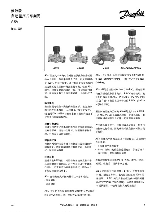
ASV-PV Plus的出厂设定为0.3bar(30kPa), 差压可在0.2bar-0.4bar(20kPa至40kPa)之间 设定。
ASV-PV出厂设定为0.1bar(10kPa),差压可 在0.05bar-0.25bar(5kPa至25kPa)之间设定。
ASV-P的差压为固定值,0.1bar(10kPa)。 ASV-PF DN50的阀门见单独样本。
2,98x1,78 G 1/16
产品编号 003L8155 003L8156 003L8157 003L8158 003L8158 003L8146 003L8147 003L8148 003L8149 003L8149 003L8143
003L8141
003L8145
003L8152
003L8153
ASV - PV 的差压控制范围为 0.05bar 至 0.25bar (5kPa至25kPa)。出厂设定为0.1bar(10kPa)。
SIBC
VD.A1.T2.41 C Danfoss 11/03
1
参数表
订货
SIBC
自动差压式平衡阀 ASV
型号
DN
mk3v/sh
内螺纹 ISO7 / 1
产品编号
15
15
1.6
R p 1/2
003L7 601
20
2.5
R p 3/4
003L7 602
25
4.0
R p1
003L7 603
32
6.3
R p1 1/4
003L7 604
40
10
R p1 1/2
003L7 605
型号
内螺纹 ISO228 / 1
G 1/2A
OMEGA PV100 电子控制比例阀说明书
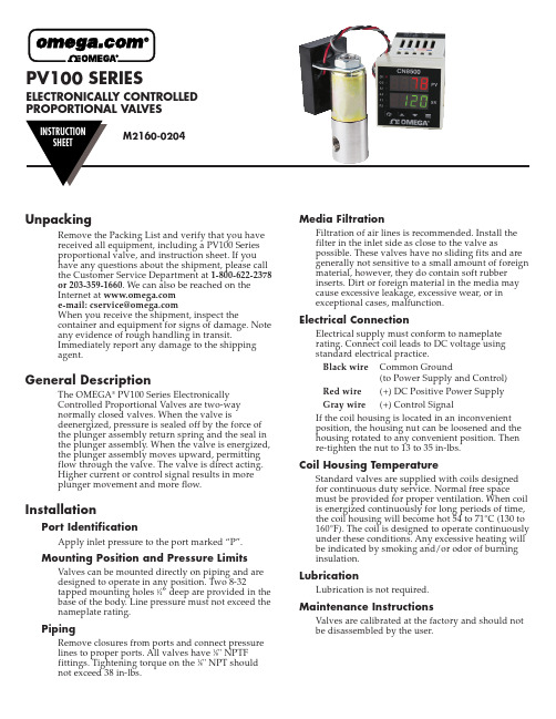
PV100 SERIES ELECTRONICALLY CONTROLLEDPROPORTIONAL VALVESUnpackingRemove the Packing List and verify that you havereceived all equipment, including a PV100 Seriesproportional valve, and instruction sheet. If youhave any questions about the shipment, please callthe Customer Service Department at 1-800-622-2378or 203-359-1660. We can also be reached on theInternet at e-mail:******************When you receive the shipment, inspect thecontainer and equipment for signs of damage. Noteany evidence of rough handling in transit.Immediately report any damage to the shippingagent.General DescriptionThe OMEGA®PV100 Series ElectronicallyControlled Proportional Valves are two-waynormally closed valves. When the valve isdeenergized, pressure is sealed off by the force ofthe plunger assembly return spring and the seal inthe plunger assembly. When the valve is energized,the plunger assembly moves upward, permittingflow through the valve. The valve is direct acting.Higher current or control signal results in moreplunger movement and more flow.InstallationPort IdentificationApply inlet pressure to the port marked “P”.Mounting Position and Pressure Limits Valves can be mounted directly on piping and aredesigned to operate in any position. Two 8-32tapped mounting holes 1⁄4” deep are provided in thebase of the body. Line pressure must not exceed thenameplate rating.PipingRemove closures from ports and connect pressurelines to proper ports. All valves have 1⁄8" NPTFfittings. Tightening torque on the 1⁄8" NPT shouldnot exceed 38 in-lbs.Media FiltrationFiltration of air lines is recommended. Install thefilter in the inlet side as close to the valve aspossible. These valves have no sliding fits and aregenerally not sensitive to a small amount of foreign material, however, they do contain soft rubberinserts. Dirt or foreign material in the media maycause excessive leakage, excessive wear, or inexceptional cases, malfunction.Electrical ConnectionElectrical supply must conform to nameplaterating. Connect coil leads to DC voltage usingstandard electrical practice.Black wire Common Ground(to Power Supply and Control) Red wire(+) DC Positive Power SupplyGray wire(+) Control SignalIf the coil housing is located in an inconvenientposition, the housing nut can be loosened and thehousing rotated to any convenient position. Thenre-tighten the nut to 13 to 35 in-lbs.Coil Housing TemperatureStandard valves are supplied with coils designedfor continuous duty service. Normal free spacemust be provided for proper ventilation. When coil is energized continuously for long periods of time, the coil housing will become hot 54 to 71°C (130 to 160°F). The coil is designed to operate continuously under these conditions. Any excessive heating will be indicated by smoking and/or odor of burninginsulation.LubricationLubrication is not required.Maintenance InstructionsValves are calibrated at the factory and should notbe disassembled by the user.Available ModelsFlow Ranges,SCCM Model Orifice Maximum At Maximum At Number Millimeters Inches C v Pressure Pressure10 PSI PV101-(*).801/320.02200 PSI0-50,0000-8,000 PV102-(*) 1.193/640.045100 PSI0-65,0000-17,000 PV103-(*) 1.591/160.0860 PSI0-75,0000-30,000 PV104-(*) 1.985/640.1240 PSI0-80,0000-45,000 *Specify Control Signal:MA for 4-20 MADC5V for 0-5 VDC10V for 0-10 VDCDimensions2SpecificationsValve Type:2-Way Normally ClosedWetted Parts:Stainless Steel with Viton SealsPower:12-24 VDCPower Consumption:7 Watts MaximumControl Signals:0-5 VDC, 0-10 VDC, 4-20 MADCAmbient Temperature Range:-10 to 50°C(14 to 122°F)Media Temperature Range:-18 to 82°C(0 to 180°F)Linear Control Range:15-85% of Full FlowResponse Time for Complete CycleOff - Full Open - Off:40 msec @ 0 pressure100 msec @ maximum pressureRepeatability:±5% when in operating linear control rangeElectrical Connection:18" color-coded lead wiresWiring:Red DC Power SupplyGray Control Signal (+)Black Common (to Power and Control) Pressure Connections:1⁄8" NPTFEnclosure:General Purpose, NEMA-13It is the policy of OMEGA Engineering, Inc. to comply with all worldwide safety and EMC/EMI regulations that apply. OMEGA is constantly pursuing certification of its products to the European New Approach Directives. OMEGA will add the CE mark to every appropriate device upon certification.The information contained in this document is believed to be correct, but OMEGA accepts no liability for any errors it contains, and reserves the right to alter specifications without notice.WARNING: These products are not designed for use in, and should not be used for, human applications.WARRANTY/DISCLAIMEROMEGA ENGINEERING, INC. warrants this unit to be free of defects in materials and workmanship for a period of 13 months from date of purchase.OMEGA’s WARRANT Y adds an additional one (1) month grace period to the normal one (1) year product warranty to cover handling and shipping time. This ensures that OMEGA’s customers receive maximum coverage on each product.If the unit malfunctions, it must be returned to the factory for evaluation. OMEGA’s Customer Service Department will issue an Authorized Return (AR)number immediately upon phone or written request. Upon examination by OMEGA, if the unit is found to be defective, it will be repaired or replaced at no charge. OMEGA’s WARRANTY does not apply to defects resulting from any action of the purchaser, including but not limited to mishandling,improper interfacing, operation outside of design limits, improper repair, or unauthorized modification. This WARRANTY is VOID if the unit shows evidence of having been tampered with or shows evidence of having been damaged as a result of excessive corrosion; or current, heat, moisture or vibration; improper specification; misapplication; misuse or other operating conditions outside of OMEGA’scontrol. Components in which wear is not warranted, include but are not limited to contact points, fuses, and triacs.OMEGA is pleased to offer suggestions on the use of its various products. However, OMEGA neither assumes responsibility for any omissions or errors nor assumes liability for any damages that result from the use of its products in accordance with information provided by OMEGA, either verbal or written. OMEGA warrants only that the parts manufactured by the company will be as specified and free of defects. OMEGA MAKES NO OTHER WARRANTIES OR REPRESENTATIONS OF ANY KIND WHATSOEVER, EXPRESSED OR IMPLIED, EXCEPT THAT OF TITLE, AND ALL IMPLIED WARRANTIES INCLUDING ANY WARRANTY OF MERCHANTABILITY AND FITNESS FOR A PARTICULAR PURPOSE ARE HEREBY DISCLAIMED. LIMITATION OF LIABILITY : The remedies of purchaser set forth herein are exclusive, and the total liability of OMEGA with respect to this order, whether based on contract, warranty, negligence, indemnification, strict liability or otherwise,shall not exceed the purchase price of the component upon which liability is based. In no event shall OMEGA be liable for consequential,incidental or special damages.CONDITIONS: Equipment sold by OMEGA is not intended to be used, nor shall it be used: (1) as a “Basic Component” under 10 CFR 21 (NRC), used in or with any nuclear installation or activity; or (2) in medical applications or used on humans. Should any Product(s) be used in or with any nuclear installation or activity, medical application, used on humans, or misused in any way, OMEGA assumes no responsibility as set forth in our basic WARRANT Y/DISCLAIMER language, and, additionally, purchaser will indemnify OMEGA and hold OMEGA harmless from any liability or damage whatsoever arising out of the use of the Product(s) in such a manner.Servicing North America:U.S.A.:One Omega Drive, Box 4047ISO 9001 CertifiedStamford, CT 06907-0047Tel: (203) 359-1660FAX: (203) 359-7700e-mail:**************Canada:976 BergarLaval (Quebec) H7L 5A1, Canada Tel: (514) 856-6928FAX: (514) 856-6886e-mail:*************For immediate technical or application assistance:U.S.A. and Canada:Sales Service: 1-800-826-6342 / 1-800-TC-OMEGA ®Customer Service: 1-800-622-2378 / 1-800-622-BEST ®Engineering Service: 1-800-872-9436 / 1-800-USA-WHEN ®TELEX: 996404 EASYLINK: 62968934 CABLE: OMEGAMexico:En Espan ˜ol: (001) 203-359-7803e-mail:*****************FAX: (001) 203-359-7807**************.mxOMEGAnet ®Online Service Internet e-mail***********************Servicing Europe:Benelux:Postbus 8034, 1180 LA Amstelveen, The Netherlands Tel: +31 (0)20 3472121FAX: +31 (0)20 6434643Toll Free in Benelux: 0800 0993344e-mail:*****************Czech Republic:Frystatska 184, 733 01 Karviná, Czech Republic Tel: +420 (0)59 6311899FAX: +420 (0)59 6311114Toll Free: 0800-1-66342e-mail:*****************France:11, rue Jacques Cartier, 78280 Guyancourt, France Tel: +33 (0)1 61 37 2900FAX: +33 (0)1 30 57 5427Toll Free in France: 0800 466 342e-mail:**************Germany/Austria:Daimlerstrasse 26, D-75392 Deckenpfronn, GermanyTel: +49 (0)7056 9398-0FAX: +49 (0)7056 9398-29TollFreeinGermany************e-mail:*************United Kingdom:One Omega Drive, River Bend Technology CentreISO 9002 CertifiedNorthbank, Irlam, Manchester M44 5BD United Kingdom Tel: +44 (0)161 777 6611FAX: +44 (0)161 777 6622Toll Free in United Kingdom: 0800-488-488e-mail:**************.ukRETURN REQUESTS /INQUIRIESDirect all warranty and repair requests/inquiries to the OMEGA Customer Service Department. BEFORE RETURNING ANY PRODUCT (S) T OOMEGA, PURCHASER MUST OBTAIN AN AUTHORIZED RETURN (AR) NUMBER FROM OMEGA’S CUSTOMER SERVICE DEPARTMENT (IN ORDER T O AVOID PROCESSING DELAYS). T he assigned AR number should then be marked on the outside of the return package and on any correspondence.The purchaser is responsible for shipping charges, freight, insurance and proper packaging to prevent breakage in transit.FOR WARRANTY RETURNS, please have the following information available BEFORE contacting OMEGA:1.Purchase Order number under which the product was PURCHASED,2.Model and serial number of the product under warranty, and3.Repair instructions and/or specific problems relative to the product.FOR NON-WARRANTY REPAIRS,consult OMEGA for current repair charges.Have the following information available BEFORE contacting OMEGA:1. Purchase Order number to cover the COST of the repair,2.Model and serial number of the product, and3.Repair instructions and/or specific problems relative to the product.OMEGA’s policy is to make running changes, not model changes, whenever an improvement is possible. T his affords our customers the latest in technology and engineering.OMEGA is a registered trademark of OMEGA ENGINEERING, INC.© Copyright 2004 OMEGA ENGINEERING, INC. All rights reserved. This document may not be copied, photocopied, reproduced, translated, or reduced to any electronic medium or machine-readable form, in whole or in part, without the prior written consent of OMEGA ENGINEERING, INC.。
丹佛斯产品册中文
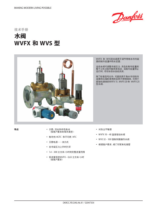
MAKING MODERN LIVING POSSIBLE特点y y介质:淡水和中性盐水(按客户要求的海水类型)yy y制冷剂:HCFC y和不可燃y HFC yy y无需电源——自力式yy y在冷凝压力上升时打开yy 1.4 – 300 立方米/小时的完整流量范围yy y低流量型的WVFX – 0,63 立方米/小时y(按客户要求)yy y对灰尘不敏感yy WVFX 10 – 40 直接驱动水阀yy WVS 32 – 100 强制伺服操作水阀y y y根据客户需求,阀门可配有毛细管技术手册水阀WVFX 和 WVS 型WVFX y和y WVS型水阀用于调节带有水冷冷凝器的制冷装置中的水流量。
这些水阀可调整冷凝压力,并且在制冷装置的整个工作过程中维持其恒定。
当制冷装置停止运行时,冷却水供水自动关闭。
除了标准型号以外,可提供用于海水冷却的冷凝器和压缩机使用的采用不锈钢阀体,可用于腐蚀性液体的WVFX 15、WVFX 20 和y WVFX 25型水阀。
参数表 水阀,WVFX 和 WVS 型技术参数1) k v值为水在通过阀的压差等于 1 bar时的流量,单位为[立方米/小时],密度ρ = 1000 千克/立方米。
2)完全打开阀则需要比使用压力范围为 3.5-16 bar的WVFX阀压力高y33%y的压力,3) WVFX 15、WVFX 20 和y WVFX 25型水阀可提供不锈钢阀体。
WVFX 10 – 40 为直接驱动调节阀yWVS 32 – 100 为伺服操作调节阀介质温度范围yWVFX 10 – 25: -25 – 130 °C yWVFX y32 – 40: -25 – 90 °C yWVS:y y-25 – 90 °C y如果一个WVS型调节器需要 1 - 10 bar y的开启压力差时,y必须更换阀的伺服弹簧。
见“订货”部分。
开启压力差yWVFX 10 – 25:yy最大 10 bar y WVFX 32 – 40:yy最大 10 bar y WVS 32 – 40:yy最小 0.5 bar:y y最大 4 bar y WVS 50 – 100:yy最小 0.3 bar;y y最大 4 bar y低于最大负荷的 20% 时,WVSy实际上将作为一个开关调节器。
丹佛斯Danfoss动态压差平衡阀ASV参数表-水力平衡
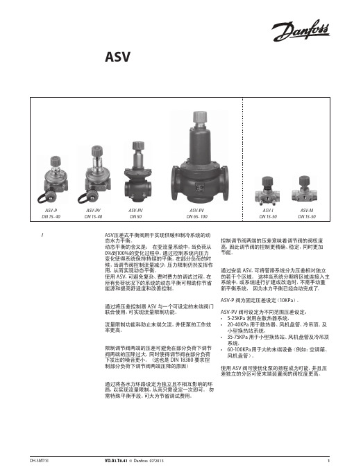
图 4 ASV用于地板采暖系统中分集水器前
ASV 阀用于地板采暖系统。为实现对每个环路的 流量限制,应将带有预设定的分集水器与 ASV-PV 阀提供的恒定压差控制配合使用。或者通过使用
具有设定功能 ASV-I 实现对整个分集水器的流量 限制。
如需不同的设定压差,ASV-PV 的设定压差具有数 个的可选范围。由于尺寸紧凑,ASV 动态压差平衡 阀易于安装于挂墙的分集水器安装盒内。
型号
备注
螺纹尾管(1 件)
焊接尾管(1 件)
连接至管道 R½ R¾ R1 R 1¼ R 1½
R2
DN 15 DN 20 DN 25 DN 32 DN 40
DN 50
注意: ASV-PV DN 50 (2½”) 和 ASV-I/M DN 50 (2¼”) 的接头口径不同。 1) 与 ASV-PV DN 50 阀配套使用 2) 与 ASV-I 和 ASV-M DN 50 配套使用。
ASV-P 阀为固定压差设定(10KPa)。
ASV-PV 阀可设定为不同范围压差设定: • 5-25KPa 常用在散热器系统, • 20-40KPa 用于散热器、风机盘管、冷吊顶、及
小型换热站系统, • 35-75KPa 用于小型换热站、风机盘管及冷吊顶
系统, • 60-100KPa 用于大的末端设备(例如:空调箱、
22
VD.A1.T8.41 © Danfoss 07/2013
DH-SMT/SI
DH-SMT/SI
VD.A1.T8.41 © Danfoss 07/2013
3
参数表 描述 / 应用 (续)
动态压差平衡阀 ASV
参数表
保温材料
图 +5 ASV 用于风机盘管系统
Danfoss 多压力放行阀值用户手册说明书
Revised 11/01/85AX437060129637en-000101Multi-Pressure Relief ValvesCG-(H)-06-*(V)-(P)*DG(L)-0*-(H)-*-20CG-(H)-10-*(V)-(P)*DG(L)-0*-(H)-*-20Parts Manualby Danfoss#3DG4S4-010N-*-51Pilot Valve(Refer to I-3471-S for parts information)DG4S4-010A-*-50Pilot Valve(Refer to I-3478-S for parts information)Model CodeFor satisfactory service life of these components in industrial applications,use full flow filtrationto provide fluid which meets ISO cleanliness code18/15or cleaner.Printed in U.S.A.Danfoss Power Solutions is a global manufacturer and supplier of high-quality hydraulic and electric components.We specialize in providing state-of-the-art technology and solutions that excel in the harsh operating conditions of the mobile off-highway market as well as the marine sector.Building on our extensive applications expertise,we work closely with you to ensure exceptional performance for a broad range of applications.We help you and other customers around the world speed up system development,reduce costs and bring vehicles and vessels to market faster.Danfoss Power Solutions –your strongest partner in mobile hydraulics and mobile electrification.Go to for further product information.We offer you expert worldwide support for ensuring the best possible solutions foroutstanding performance.And with an extensive network of Global Service Partners,we also provide you with comprehensive global service for all of our components.Local address:DanfossPower Solutions GmbH &Co.OHG Krokamp 35D-24539Neumünster,Germany Phone:+4943218710DanfossPower Solutions ApS Nordborgvej 81DK-6430Nordborg,Denmark Phone:+4574882222DanfossPower Solutions (US)Company 2800East 13th Street Ames,IA 50010,USA Phone:+15152396000DanfossPower Solutions Trading (Shanghai)Co.,Ltd.Building #22,No.1000Jin Hai Rd Jin Qiao,Pudong New District Shanghai,China 201206Phone:+862120806201Danfoss can accept no responsibility for possible errors in catalogues,brochures and other printed material.Danfoss reserves the right to alter its products without notice.This also applies to products already on order provided that such alterations can be made without subsequent changes being necessary in specifications already agreed.All trademarks in this material are property of the respective companies.Danfoss and the Danfoss logotype are trademarks of Danfoss A/S.All rights reserved.Products we offer:•Cartridge valves •DCV directional control valves•Electric converters •Electric machines •Electric motors •Gear motors •Gear pumps •Hydraulic integrated circuits (HICs)•Hydrostatic motors •Hydrostatic pumps •Orbital motors •PLUS+1®controllers •PLUS+1®displays •PLUS+1®joysticks and pedals•PLUS+1®operator interfaces•PLUS+1®sensors •PLUS+1®software •PLUS+1®software services,support and training •Position controls and sensors•PVG proportional valves •Steering components and systems •TelematicsHydro-Gear Daikin-Sauer-Danfoss。
丹佛斯Danfoss生活热水循环系统多功能恒温阀MTCV-水力平衡
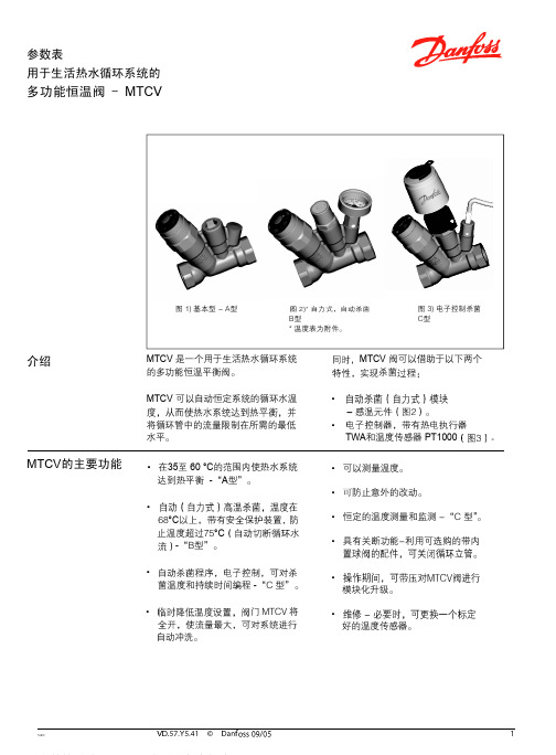
多功能恒温阀 - MTCV
50 ˚C下 在 35 ˚C下
在 60˚C下
流 量 水 温 温 度 ˚C
预设
预设
预设
预设
预设
预设
水温 ˚C
流量温度 ˚C
B型 C型
数据表 计算举例
多功能恒温阀 - MTCV
8 个立管进行计算。
VD.57.X1.02
•
q1 =10
*
*
- 管路的尺寸 - 绝热层的材料 - 装管子处的环境温度 - 绝热层的效率和条件
•
Tsup = 55 °C
•
∆T= 5 K
•
•
l = 10 m
•
I 基本操作
• 每个立管中热量损失的计算
Qr
Qh
Qr = l立管x q = (10+10) x10 = 200 m
Qh= l 水平 x q = 10 x 10= 100 m
•表3
立管
立管中 Qr
顶部 Qh
热量损失 每一部分的 总的损失
ΣQ 总
阀 – 基本型A型
产品编号
阀体 ................................................Rg 5 O型密封圈 ...................................EPDM
. 不锈钢
高温杀菌模块 -B型
描述
产品编号
ESMB PT1000用插座
CCR2控制器
• 模块化升级。
• 好的温度传感器。
数据表 功能
多功能恒温阀 - MTCV
1-A型。
当水温比设定值高 5°
MTCV 是一种自力式比例控制的恒温控制
丹弗斯PVG32系列比例多路阀样本
Revision history Table of revisionsTechnical InformationPVG 32 Proportional Valve Group2 | © Danfoss | August 2017520L0344 | BC00000038en-US0802General descriptionFeatures of PVG 32...........................................................................................................................................................................5PVG modules .....................................................................................................................................................................................5PVP, pump side modules..........................................................................................................................................................5PVB, basic modules.....................................................................................................................................................................5Actuation modules.....................................................................................................................................................................6Remote control units ......................................................................................................................................................................6PVG 32 with open center PVP......................................................................................................................................................7PVG 32 with closed center PVP....................................................................................................................................................8PVG 32 sectional view.....................................................................................................................................................................9Load sensing for variable displacement pump supply.......................................................................................................9Safety in applicationControl system example..............................................................................................................................................................12Examples of wiring block diagram.....................................................................................................................................14FunctionLoad sensing controls...................................................................................................................................................................16LS control with bleed orifice (do not use with PVG valves).......................................................................................16Integral PC function.................................................................................................................................................................16Load sensing system characteristics:.................................................................................................................................16Remote pressure compensated controls..............................................................................................................................16Remote pressure compensated system characteristics:............................................................................................17Typical applications for remote pressure compensated systems:..........................................................................17PVG 32 main spool with pressure compensated control................................................................................................17Pressure compensated system characteristics..............................................................................................................18Typical applications for pressure compensated systems...........................................................................................18PVPC adapter for external pilot oil supply............................................................................................................................18PVPC with check valve for open center PVP...................................................................................................................18PVPC without check valve for open or closed center PVP.........................................................................................19PVMR, friction detent....................................................................................................................................................................21PVMF, mechanical float position lock.....................................................................................................................................21PVBS, main spools for flow control (standard)....................................................................................................................21PVBS, main spools for flow control (linear characteristic)...............................................................................................21PVBS, main spools for pressure control.................................................................................................................................22Background.................................................................................................................................................................................22Principle.......................................................................................................................................................................................22Application..................................................................................................................................................................................23Sizing.............................................................................................................................................................................................23Limitation....................................................................................................................................................................................24PVPX, electrical LS unloading valve.........................................................................................................................................24PVG 32 technical dataPVH, hydraulic actuation.............................................................................................................................................................26PVM, mechanical actuation........................................................................................................................................................26PVE, electrical actuation..............................................................................................................................................................26PVPX, electrical LS unloading valve.........................................................................................................................................29Electrical actuationElectrical control of PVG..............................................................................................................................................................30Closed loop control.......................................................................................................................................................................31PVEO...................................................................................................................................................................................................32PVEM...................................................................................................................................................................................................32PVEA, PVEH, PVES, PVEU..............................................................................................................................................................33PVEP....................................................................................................................................................................................................33PVED-CC and PVED-CX.................................................................................................................................................................33PVHC...................................................................................................................................................................................................34Technical characteristicsGeneral...............................................................................................................................................................................................36PVP, pump side module.. (36)Technical InformationPVG 32 Proportional Valve GroupContents© Danfoss | August 2017520L0344 | BC00000038en-US0802 | 3PVB, basic modules oil flow characteristics..........................................................................................................................36Pressure-compensated PVB, open center PVP ..............................................................................................................37PVB without pressure compensation, open center PVP.............................................................................................38PVB without pressure compensation, closed center PVP..........................................................................................39PVLP, shock and PVLA, suction valves...............................................................................................................................41Pressure build-up for pressure controlled spools.........................................................................................................41Pressure control spool flow characteristics..........................................................................................................................41Examples of how to use the characteristics for pressure control spools...................................................................42Characteristics for float position main spools (43)Hydraulic systemsManually actuated PVG 32 – fixed displ. pump..................................................................................................................45Electrically actuated PVG 32 – variable displ. pump.........................................................................................................46Other operating conditionsOil.........................................................................................................................................................................................................47Particle content, degree of contamination...........................................................................................................................47Filtration............................................................................................................................................................................................47DimensionsPVM, control lever positions......................................................................................................................................................50Surface treatment.. (51)Modules symbols, description and code numbersPVP, pump side modules.............................................................................................................................................................52PVB, basic modules........................................................................................................................................................................54PVLA, suction valve (fitted in PVB)...........................................................................................................................................56PVLP, shock and suction valve (fitted in PVB)......................................................................................................................56PVM, mechanical actuation........................................................................................................................................................57PVH, hydraulic actuation.............................................................................................................................................................58PVS, end plate..................................................................................................................................................................................58PVAS, assembly kit.........................................................................................................................................................................58PVPX, electrical LS unloaded valve..........................................................................................................................................58PVPC, plug for external pilot oil supply..................................................................................................................................59Module selection chartStandard FC spools........................................................................................................................................................................60Standard FC spools, hydraulic actuation...............................................................................................................................61FC spools for mechanical float position, PVMF...................................................................................................................61FC spools for friction detent, PVMR.........................................................................................................................................62FC spools with linear flow characteristic ..............................................................................................................................62Standard PC spools .......................................................................................................................................................................63Standard PC spools, hydraulic actuation...............................................................................................................................64PVB, basic valves.............................................................................................................................................................................65PVP, pump side module..............................................................................................................................................................66PVE, electrical actuation..............................................................................................................................................................68Order specificationStandard and option assembly.................................................................................................................................................70Reordering........................................................................................................................................................................................70Pressure setting limits..................................................................................................................................................................70PVG 32 specification sheet (72)Technical InformationPVG 32 Proportional Valve GroupContents4 | © Danfoss | August 2017520L0344 | BC00000038en-US0802PVG 32 is a hydraulic load sensing valve designed to give maximum flexibility. From a simple load sensing directional valve, to an advanced electrically controlled load-independent proportional valve.The PVG 32 modular system makes it possible to build up a valve group to meet requirements precisely.The compact external dimensions of the valve remain unchanged whatever combination is specified.Features of PVG 32•Load-independent flow control:‒Oil flow to an individual function is independent of the load pressure of this function‒Oil flow to one function is independent of the load pressure of other functions •Good regulation characteristics •Energy-saving•Up to 12 basic modules per valve group •Several types of connection threads •Low weight•Compact design and installationPVG modulesPVP, pump side modules•Built-in pressure relief valve •Pressure gauge connection•Versions:‒Open center version for systems with fixed displacement pumps‒Closed center version for systems with variable displacement pumps ‒Pilot oil supply for electrical actuator built into the pump side module ‒Pilot oil supply for hydraulic actuation built into the pump side module ‒Versions prepared for electrical LS unloading valve PVPXPVB, basic modules•Interchangeable spools•Depending on requirements the basic module can be supplied with:‒Integrated pressure compensator in channel P‒Load holding check valve in channel P ‒Shock/suction valves for A and B portsTechnical InformationPVG 32 Proportional Valve GroupGeneral description© Danfoss | August 2017520L0344 | BC00000038en-US0802 | 5‒LS pressure limiting valves individually adjustable for ports A and B ‒Different interchangeable spool variants‒All versions suitable for mechanical, hydraulic and electrical actuationActuation modulesThe basic module is always fitted with mechanical actuator PVM and PVMD, which can be combined with the following as required:•Electrical actuator (11 - 32 V ===):‒PVES – proportional, Super‒PVEH – proportional, High performance ‒PVEH-F – proportional high performance, Float ‒PVEA – proportional low hysteresis ‒PVEM – proportional, Medium performance ‒PVEO – ON/OFF‒PVEH-U/PVES-U – proportional, voltage control, 0-10 V ‒PVED-CC – Digital CAN controlled J1939/ISOBUS ‒PVED-CX – Digital CAN controlled CANopen X-tra safety ‒PVEP – PWM voltage controlled (11-32 V)‒PVHC – High Current actuator for PVG•PVMR, cover for Mechanical detent •PVMF, cover for Mechanical Float •PVH, cover for Hydraulic actuationRemote control units•Electrical remote control units:‒PVRE, PVRET ‒PVREL ‒PVRES ‒Prof 1‒Prof 1 CIP ‒JS120‒JS1000 Ball grip ‒JS1000 PRO grip ‒JS2000‒JS6000‒JS7000•Hydraulic remote control unit: PVRHHTechnical InformationPVG 32 Proportional Valve GroupGeneral description6 | © Danfoss | August 2017520L0344 | BC00000038en-US0802Electrical and hydraulic remote control unitsPVRE, electrical control unit, 162F…PVREL, electrical control unit, 155U…PVRH, hydraulic control unit, 155N…155N0003 155N0001155N0004 155N0005 155N0002PVG 32 with open center PVPPVG 32 with open center PVP (fixed displacement pump) and PVB with flow control spool.When the pump is started and the main spools in the individual basic modules (11) are in the neutral position, oil flows from the pump, through connection P, across the pressure adjustment spool (6) to tank.The oil flow led across the pressure adjustment spool determines the pump pressure (stand-by pressure).When one or more of the main spools are actuated, the highest load pressure is fed through the shuttle valve circuit (10) to the spring chamber behind the pressure adjustment spool (6), and completely or partially closes the connection to tank to maintain pump pressure.Pump pressure is applied to the right-hand side of the pressure adjustment spool (6).The pressure relief valve (1) will open should the load pressure exceed the set value, diverting pump flow back to tank.In a pressure-compensated basic module the compensator (14) maintains a constant pressure drop across the main spool – both when the load changes and when a module with a higher load pressure is actuated.With a non pressure-compensated basic module incorporating a load drop check valve (18) in channel P,the check valve prevents return oil flow.The basic module can be supplied without the load drop check valve in channel P for functions with over-center valves.The shock valves PVLP (13) with fixed setting and the suction valves PVLA (17) on ports A and B are used for the protection of the individual working function against overload and/or cavitation.Technical InformationPVG 32 Proportional Valve GroupGeneral description© Danfoss | August 2017520L0344 | BC00000038en-US0802 | 7An adjustable LS pressure limiting valve (12) can be built into the A and B ports of pressure-compensated basic modules to limit the pressure from the individual working functions. Please see the sectional drawing PVG 32 sectional view on page 9 below for better understanding of this example.The LS pressure limiting valves save energy compared with the shock valves PVLP:•with PVLP all the oil flow to the working function will be led across the combined shock and suctionvalves to tank if the pressure exceeds the fixed setting.•with LS pressure limiting valves an oil flow of about 2 l/min [0.5 US gal/min] will be led across the LSpressure limiting valve to tank if the pressure exceeds the valve setting.PVG 32 with closed center PVPPVG 32 with closed center PVP (variable displacement pump) and PVB with flow control spool.In the closed center version of PVP an orifice (5) and a plug (7) have been fitted instead of the plug (4).This means that the pressure adjustment spool (6) will only open to tank when the pressure in channel P exceeds the set value of the pressure relief valve (1).In load sensing systems the load pressure is led to the pump control via the LS connection (8).In the neutral position the pump load sense control sets the displacement so that leakage in the system is compensated, to maintain the set stand-by pressure.When a main spool is actuated the pump load sense control will adjust the displacement so that the set differential pressure (margin) between P and LS is maintained.The pressure relief valve (1) in PVP should be set at a pressure of approx. 30 bar [435 psi] above maximum system pressure (set on the pump or external pressure relief valve).Technical InformationPVG 32 Proportional Valve GroupGeneral description8 | © Danfoss | August 2017520L0344 | BC00000038en-US0802PVG 32 sectional viewPVPPVBPVB1. Pressure relief valve11. Main spool2. Pressure reduction valve for pilot oil supply 12. LS pressure limiting valve3. Pressure gauge connection 13. Shock and suction valve, PVLP4. Plug, open center 14. Pressure compensator5. Orifice, closed center 15. LS connection, port A6. Pressure adjustment spool 16. LS connection, port B7. Plug, closed center 17. Suction valve, PVLA8. LS connection 18. Load drop check valve9. LS signal 19. Pilot oil supply for PVE10. Shuttle valve20. Maximum oil flow adjustment screws for A/B portsLoad sensing for variable displacement pump supplyThe pump receives fluid directly from the reservoir through the inlet line. A screen in the inlet lineprotects the pump from large contaminants.Technical InformationPVG 32 Proportional Valve GroupGeneral description© Danfoss | August 2017520L0344 | BC00000038en-US0802 | 9The pump outlet feeds directional control valves such as PVG-32, hydraulic integrated circuits (HIC), and other types of control valves.The PVG valve directs and controls pump flow to cylinders, motors and other work functions. A heat exchanger cools the fluid returning from the valve. A filter cleans the fluid before it returns to the reservoir.Flow in the circuit determines the speed of the actuators. The position of the PVG valve spool determines the flow demand. A hydraulic pressure signal (LS signal) communicates demand to the pump control.The pump control monitors the pressure differential between pump outlet and the LS signal, and regulates servo pressure to control the swashplate angle. Swashplate angle determines pump flow.Actuator load determines system pressure. The pump control monitors system pressure and will decrease the swashplate angle to reduce flow if system pressure reaches the pump control setting.A secondary system relief valve in the PVG valve acts as a back-up to control system pressure.Pictorial circuit diagramTechnical InformationPVG 32 Proportional Valve GroupGeneral description10 | © Danfoss | August 2017520L0344 | BC00000038en-US0802Safety in applicationAll types of control valves (incl. proportional valves) can fail, thus the necessary protection against theserious consequences of function failure should always be built into the system. For each application anassessment should be made for the consequences of pressure failure and uncontrolled or blockedmovements. To determine the degree of protection that is required to be built into the application,system tools such an FMEA (Failure Mode and Effect Analysis) and Hazard and Risk Analysis can be used.FMEA – IEC EN 61508FMEA (Failure Mode and Effect Analysis) is a tool used for analyzing potential risks. This analyticaltechnique is utilized to define, identify, and prioritize the elimination or reduction of known and/orpotential failures from a given system before it is released for production. Please refer to the standard IECFMEA 61508.Hazard and risk analysis ISO 12100-1/14121This analysis is a tool used in new applications as it will indicate whether there are special safetyconsiderations to be met according to the machine directives EN 13849. Dependent on the determinedlevels conformity this analysis will detirmine if any extra requirements for the product design,development process, production process or maintenance, example the complete product life cycle.W WarningAll brands and all types of directional control or proportional valves, which are used in many differentoperation conditions and applications, can fail and cause serious damage.Analyze all aspects of the application. The machine builder/system integrator alone is responsible formaking the final selection of the products and assuring that all performance, safety and warningrequirements of the application are met. The process of choosing the control system and safety levels isgoverned by the machine directives EN 13849 (Safety related requirements for control systems).Control system exampleExample of a control system for manlift using PVE Fault monitoring input signals and signals from external sensors to ensure the PLUS+1® maincontrollers correct function of the manlift.Safety in applicationElectrical block diagram for the above illustrationWWarningIt is the responsibility of the equipment manufacturer that the control system incorporated in the machine is declared as being in conformity with the relevant machine directives.PVG 32 – mainly used in system with fixed displacement pumps:•PVSK, commonly used in crane application - full flow dump •PVPX, LS dump to tankPVG 100 – alternative LS dump or pilot supply disconnect:•PVPP, pilot oil supply shut off•External cartridge valve connecting LS pressure or main pressure to tank PVG 120 – pump disconnect / block for variable pumps:Safety in applicationSafety in application•PVPE, full flow dump for the PVG 120•External cartridge valve connecting LS pressure to tankExamples of wiring block diagramExample of a typical wiring block diagram using PVEH with neutral power off switch and fault monitoringoutput for hydraulic deactivation.A– Emergency stop / man present switchB– PVE Fault monitoring signalsC– Neutral signal detection.D– Hydraulic deactivationSystem Control Logic e.g. PLUS+1® for signal monitoring and triggering signal for deactivation of thehydraulic system.W WarningIt is the responsibility of the equipment manufacturer that the control system incorporated in themachine is declared as being in conformity with the relevant machine directives.。
萨澳(SAUER DANFOSS)全系列产品介绍

转角传感器
控制手柄 (JS6000)
转向器 (OSPC LS) SASA
控制器 (PLUS+1™)
比例阀组 (PVG)
变量泵 (45系列)
CAN 总线
轮式装载机转向系统
工作系统
对于工作系统,萨澳-丹佛斯的解决方案不胜枚举。比如,我们所提供的人体工程学手柄,极大改善了操作舒
适度;利用LS技术,可以起到节能作用;不同的控制模式可供操作人员选择;零泄漏插装阀模块可选;通过
终端设备 (DP630)
摄像头 (CCC102)
传送
清选
马达
(OMH, OMP, OMS, OMV, OMR)
பைடு நூலகம்
比例阀组 (PVG32)
手柄 (JS1000)
拉线传感器
控制器 (PLUS+1™)
变量马达 (H1B)
ASC 防打滑阀
程序调试工具
前进/停止/ 后退
甜菜收割机控制系统
柱塞泵 (H1)
5
One of the Industry’s Broadest Product Portfolios
工厂位于
Nordborg 丹麦
工厂位于
Neumünster 德国
工厂位于
Shanghai 中国
工厂位于
Osaka 日本
全球网络
工厂位于
Ames, IA 美国
萨澳-丹佛斯总部 萨澳-丹佛斯工厂 萨澳-丹佛斯-大金总部 萨澳-丹佛斯-大金工厂
工厂
Älmhult, 瑞典 Ames, IA, 美国 Bielany Wroclawskie, 波兰 Bologna, 意大利 Caxias do Sul, 巴西 Dubnica nad Váhom, 斯洛伐克 Easley, SC, 美国 Freeport, IL, 美国 Kaiserslautern, 德国 Minneapolis, MN, 美国
丹福斯(Danfoss)Vane类单泵服务与零件手册说明书

I-3167-SRevised 10-01-89Vane Type Single Pump35VQ**A-86* - 20(L)36VQ**A-86 - 20(L)Service and Parts ManualDanfoss ®Vane PumpsAX432876936851en-000101– 3 –Model CodeViton SealsSeriesVane TypeSAE Rated CapacityPort ConnectionsMounting & Shaft SealsAssemblyShaftsPort PositionsDesignRotation(Omit if not required.)(Rating @ 1200 RPM - 100 psi)21 - 21 USgpm25 - 25 USgpm30 - 30 USgpm35 - 35 USgpm38 - 38 USgpmF - Foot (Single Shaft Seal Assy.)S - Flange (Double Shaft Seal Assy.)Omitted-Flange (Single Shaft SealAssy.)1 - Square Key4 - Splined11 - Splined86 - Square KeySee Chart BelowL - Left Hand (CCW Rotation)Omitted - Right Hand RotationFor satisfactory service life of these components, use full ow ltration to provide uid which meets ISO cleanliness code 16/13or cleaner. Selections from pressure, return, and in-line lter series are recommended.A - SAE 4-Bolt FlangePrinted in U.S.A.Danfoss Power Solutions is a global manufacturer and supplier of high-quality hydraulic and electric components. We specialize in providing state-of-the-art technology and solutions that excel in the harsh operating conditions of the mobile off-highway market as well as the marine sector. Building on our extensive applications expertise, we work closely with you to ensure exceptional performance for a broad range of applications. We help you and other customers around the world speed up system development, reduce costs and bring vehicles and vessels to market faster.Danfoss Power Solutions – your strongest partner in mobile hydraulics and mobile electrification.Go to for further product information.We offer you expert worldwide support for ensuring the best possible solutions foroutstanding performance. And with an extensive network of Global Service Partners, we also provide you with comprehensive global service for all of our components.Local address:DanfossPower Solutions GmbH & Co. OHG Krokamp 35D-24539 Neumünster, Germany Phone: +49 4321 871 0DanfossPower Solutions ApS Nordborgvej 81DK-6430 Nordborg, Denmark Phone: +45 7488 2222DanfossPower Solutions (US) Company 2800 East 13th Street Ames, IA 50010, USA Phone: +1 515 239 6000DanfossPower Solutions Trading (Shanghai) Co., Ltd.Building #22, No. 1000 Jin Hai Rd Jin Qiao, Pudong New District Shanghai, China 201206Phone: +86 21 2080 6201Danfoss can accept no responsibility for possible errors in catalogues, brochures and other printed material. Danfoss reserves the right to alter its products without notice. This also applies to products already on order provided that such alterations can be made without subsequent changes being necessary in specifications already agreed.All trademarks in this material are property of the respective companies. Danfoss and the Danfoss logotype are trademarks of Danfoss A/S. All rights reserved.Products we offer:•Cartridge valves •DCV directional control valves•Electric converters •Electric machines •Electric motors •Gear motors •Gear pumps •Hydraulic integrated circuits (HICs)•Hydrostatic motors •Hydrostatic pumps •Orbital motors •PLUS+1® controllers •PLUS+1® displays •PLUS+1® joysticks and pedals•PLUS+1® operator interfaces•PLUS+1® sensors •PLUS+1® software •PLUS+1® software services,support and training •Position controls and sensors•PVG proportional valves •Steering components and systems •TelematicsHydro-GearDaikin-Sauer-Danfoss。
DANFOSS-PVG100阀组
技术文献
概述 PVG 100 比例阀 技术文献 目录
概述 ................................................................................................................................................................... 4 阀组系统...................................................................................................................................................... 4 PVG 100 属性概述.................................................................................................................................... 4 PVP, 泵侧模块 ............................................................................................................................................ 4 PVB,工作模块............................................................................................................................................. 4 驱动模块...................................................................................................................................................... 4
100系列调节阀
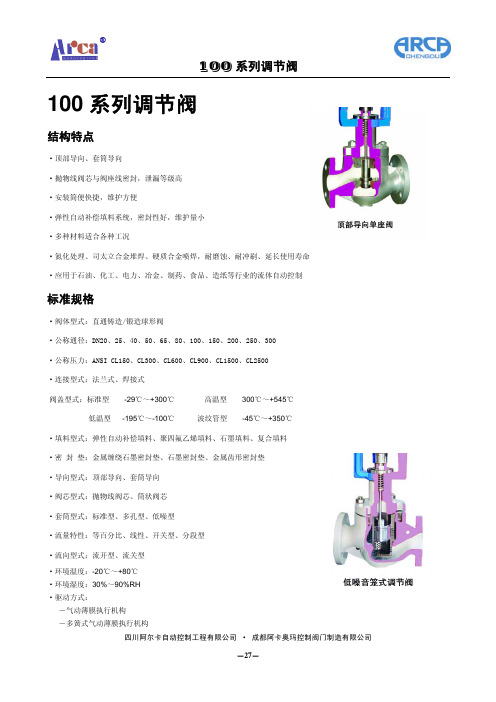
100 系列调节阀
结构长度
公称通径
公称压力
连接方式
20
25
40
50
65
80
100 150
200
250
300
3/4"
1"
1-1/2" 2" 2-1/2"
3"
4"
6"
8"
10"
12"
ANSI CL150
RF/SW/BW
184
184
222
254
276
298
352
451
543
673
737
RJ
-
197
235
316(1.4571)+(硬化处理)
304L(1.4306)+(硬化处理)
304L(1.4306)+(硬化处理)
316L(1.4404)+(硬化处理)
316L(1.4404)+(硬化处理)
2Cr13(1.4021)+硬化处理
2Cr13(1.4021)+硬化处理
304(1.4301)+(硬化处理)
304(1.4301)+PTFE
-ANSI 符合 ASME B16.34-2004;API 598-2004 -PN 符合 GB/T4213-1992;GB/T13927-1992
四川阿尔卡自动控制工程有限公司 · 成都阿卡奥玛控制阀门制造有限公司 -28-
100 系列调节阀
额定 Cv 值
·顶部导向单座阀 ·套筒导向单座阀 ·套筒导向笼式阀
17.5
11.5
丹佛斯多路阀
2
11048997 • Jun 2008
PVE(第四代) 技术文献 功能
功能
Sauer-Danfoss 的电液控制模块(PVE),将电子元件、传感器和驱动器集成为一个独立 单元,然后直接和比例阀的阀体相连。
闭环控制 集成式反馈传感器通过检测阀芯的运动产生反馈信号。根据反馈信号和输入信号对 比所得的偏差,通过一个电磁阀桥来控制主阀芯的运动方向、速度和位置。集成式 电子元件,可以补偿阀芯压力、内部泄漏、油液粘度变化、先导压力等所带来的影 响。这样可以保证系统的低迟滞和高精度。同时这些电子元件也为系统提供了内置 的安全装置,如故障监控装置、方向指示灯和LED显示灯。
新产品的设计开发由市场和客户需求决定。Sauer-Danfoss 公司对产品研发的投入促 进了产品的发展,从而维持和扩大了我们在电液控制阀领域内的市场领先地位。
用在PVE(第四代)上的技术,是基于成熟的电控原理的。这些原理来自于诸如汽车 工业领域以及我们在行走液压行业内对电控阀的长期应用经验。PVE(第四代)不仅 延续了PVE(第二代) 和PVE(第三代)所体现的高质量和高可靠性,而且在此基础 上对PVE模块进行了规范化改进 – 如环境保护因素。
11048997 • Jun 2008
比例驱动
PVE(第四代) 技术文献 电气驱动
PVES, 超高比例性能 PVES 推荐用在对迟滞和精度要求都 非常高的控制系统。
更多的技术参数请参考 PVEH
• Hirschmann, Deutsch 或 AMP 接头
液压原理图
PVEO
PVEO-R
12 KΩ 7 (3.5) W
8
11048997 • Jun 2008
PVE(第四代) 技术文献 技术参数
比例阀PV70-31中文.pdf
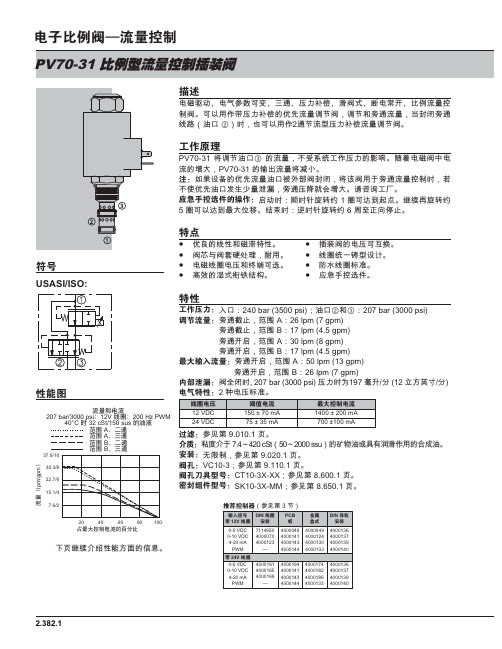
⩡ ℀ҷ䬬ÿ≭䛻䔜䟄箫洀┷ 䟄㺣莋蛖♾♧ ₘ抩 ☚┪嫴⌎ 袛梏㆞ 蛦䟄デ 秣√税摞虱Ⓟ梏 ♾芵䞷⇫サ☚┪嫴⌎䤓芼⏗税摞庒唑梏 庒唑✛礃抩税摞 ㇢⺐桼礃抩兎恾 㽈♲ 㢅 ⃮♾芵䞷⇫ 抩唑税⨚☚┪嫴⌎税摞庒唑梏҈ ⤲39 蓩庒唑㽈♲ 䤓税摞 ₜ♦籏兮ぴ⇫☚┪䤓砋❜ 椞詜䟄箫梏₼䟄税䤓盦⮶ 39 䤓戢茽税摞蓩⺞∔喝Ⱁ㨫幍䤓芼⏗税摞㽈♲缗盶肺梏⺐桼 蓩年梏䞷ℝ礃抩税摞虱Ⓟ㢅 啴ₜ∎芼⏗㽈♲♠䞮蓭摞秼䆞 礃抩☚鍟蓺芽盦⮶ 庆莧幱ぴ☑䔵Т⮰ ҈喝⚾┷㢅 欉㢅朗礈懻儵 皽♾才瘸怆䍈 其兼␜礈懻儵皽♾芵才瘸蜙⮶痒䲊 兢㧮㢅 釰㢅朗礈懻儵 ⛷綍㷲⚠痼㷱➥◥芼網䤓兎㊶✛箫袠襚㊶ 㙡遙梏䤓䟄☚♾疸㗱梏唾疭梏眀䫻⮓䚕 功䞷 兎皽兮枇⨚幍帰䟄箫兎皽䟄☚✛兗簖♾折 腋㻃兎皽㪖瘮舊磧䤓䄎㆞嫣材兢㨓 ㄣ㊴㓚虱折ↅ➥҈ 喝茤♲ EDU SVL 㽈♲ ✛ EDU SVL䄯㞮≭䛻喝礃抩硰㷱 喒⦃ $ OSP JSP礃抩硰㷱 喒⦃ % OSP JSP礃抩⚾ 喒⦃ $ OSP JSP礃抩⚾ 喒⦃ % OSP JSP䒿 ≭䛻喝礃抩⚾ 喒⦃ $ OSP JSP礃抩⚾ 喒⦃ % OSP JSP䘔⇰喝梏⏷桼㢅 EDU SVL ☚┪㢅 秧◖ ⒕ 簌礀喀⺇ ⒕䓳␐喝莋屐簛 欄Ϸ䉔喝伧矑⅚ℝ F6W VVX 䤓䪎䓸㽈㒥牑㦘䀵袛⇫䞷䤓⚗㒟㽈㷱喝蛭腏Ⓟ 莋屐簛 欄䬬 喝9& 莋屐簛 欄䬬 喝&7 ; ;; 莋屐簛 欄㏰Т 喝6. ; 00 莋屐簛 欄USASI/ISO:げ2.382.120DŽlpm/gpmDž207 bar/3000 psiǗ12V Ǘ200 Hz PWM40°C 32 cSt/150 susALjALjBLjBLj40608010037.9/1030.3/822.7/615.1/47.6/2㘩芚欄其兼⅚兜㊶賍礀槱䤓痥㋾䃎䉙2.382.2㘩 兼691000压降(bar/psi )流量(l p m /g p m )调节流量和压降二通;流量范围 A 240 bar/3500 psi ,进油口12V 线圈;200 Hz PWM 13820002073000276400037.9/1030.3/822.7/615.1/47.6/2691000压降( bar/psi )流量(l p m /g p m )调节流量和压降二通;流量范围 B 240 bar/3500 psi ,进油口12V 线圈;200 Hz PWM 13820002073000276400018.9/53.8/111.4/322.7/615.1/47.6/2 㷱䬬喝摜摞 ◒⏚ 箬ぴ⇫槱朱德₣兞扖䫻⮓䚕 盶缂槱柏枛 㪖瘮ₐ受蟇厅 2 ⨚皽✛㺮蟇厅㖰皽䬬 喝摜摞 ◒⏚箬 棂㨐㺶荩⮓䚕舊薦矑 7 杬⚗摠 欬着☚薦 EDU SVL 莋屐簛 欄 ⃮♾折䞷䚒犐枇材✛朱德梏⧦ ⻉⺇㦘硵ₜ⚛ 庆莧幱ぴ☑PV70 ㈧ ㏫ 喝摜摞 ◒⏚箬 兮䍼⫠⫠㠨⺐遙 + 儶Ⓔ功 舊䂸䆕癕兎 莋屐簛 欄PV70-31__ __ - __ __ __ - __ - __ __ __ __≭䛻㠯 ♑屐 A ㊶厌 B 㦁兎⩡ 0 㡯兎⦗ 12 9'& 24 9'&䬬 ⇥ 0 ⅔㖖㙡遙ↅ 6T 6$( 8T 6$(2B 喀⺇ %63 3B喀⺇ %63%63 梏⧦⅔棟ℝ喀⦌Ⓟ抯㪖ₐ受㳰厅 N 䭂㺮▥⚗䓸 V䔵Т 㡯 䴉䤌 ㄣ㊴㓚㘶 M ㄣ㊴ 㓚㘶サ≬棸 G㏫ ㏴〛 DS ♛蘷ㇱ碟⯃ DG ',1 DL ⺋兎DL/W ⺋兎 サ :HDWKHUSDN ®扭㘴⣷ E ㏫ ㏴〛 ER 'HXWVFK '7 3 䶵⚗ ,3 . 㪖⃮♾㙟∪␔函ℛ㨐丰䤓兎⦗ 庆✷幱ぴ☑。
丹尼逊样本
11 ~ 100 48 ~ 158 132 ~ 269 11 ~ 100
6 ~ 50
2800
275
2500
240
2200
240
2800
275
3600
300
T6*R
11 ~ 269
双联叶片泵, 定量
通用型
T6BB/T6BBS T6CC T67CB T7DB/T7DBS T67DC T7DD/T7DDS T7EB/T7EBS T67EC T7ED/T7EDS T7EE/T7EES 专用型
轴向柱塞式液压马达
3-SH 1806-A 3-SH 2301-A
3-SH 2401-A 3-SH 2401-A
变量液压马达
M 6 H/V
98
M 7 H/V
119
M 11 H/V
180
M 14 H/V
230
M 24 H
403
M 30 H
502
420
1.56
420
1.89
420
2.86
420
3.64
350
最高工作压力
bar
psi
PV/PVT 系列轴向柱塞式变量液压泵(开式回路用)
PV/PVT 6
14.4 0.88
30001)
310
PV/PVT 10
20.6 1.26
28001)
310
PV/PVT 15
34.2 2.09
25001)
310
PV/PVT 20
42.9 1.62
23001)
310
PVM/PVR 20
丹尼逊液压技术
产品样本目录
产品
轴向柱塞式液压泵 叶片泵 液压马达 方向控制阀 压力控制阀 流量控制阀 单向阀 座阀及插装阀(开关型) 叠加式液压控制阀 压力继电器 电子控制器 集成控制阀块 综合样本 技术资料
萨奥丹佛斯平衡阀样本Section09_Counterbalance_valves
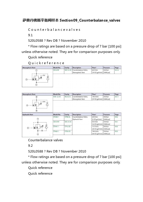
萨奥丹佛斯平衡阀样本Section09_Counterbalance_valvesC o u n t e r b a l a n c e v a l v e s9.1520L0588 ? Rev DB ? November 2010* Flow ratings are based on a pressure drop of 7 bar [100 psi] unless otherwise noted. They are for comparison purposes only.Quick referenceQ u i c k r e f e r e n c eCounterbalance valves9.2520L0588 ? Rev DB ? November 2010* Flow ratings are based on a pressure drop of 7 bar [100 psi] unless otherwise noted. They are for comparison purposes only.Quick referenceQuick referenceC o u n t e r b a l a n c e v a l v e s9.3520L0588 ? Rev DB ? November 2010Application notesA p p l i c a t i o n n o t e sA counterbalance valve provides several functions:· Free flow in one direction.· Leak-free load holding.· Protection against hydraulic line failure.· Protection against pressure shocks caused by external forces or overrunning loads · Cavitation-free motion control to match speed to pump flow when a load could cause loss of control of an actuator (cylinder or motor).·Smooth, modulated motion control when the directional valve is suddenly closed.COUNTERBALANCE VALVESCounterbalance valvesMotion control valves, also referred to as load holding valves, are used to control the motion of a load in the following ways:· Prevent a load from dropping in case of hose or tube failure.· Prevent a load from drifting caused by directional control valve spool leakage.·Provide smooth, modulated motion when the load is in a lowering or run-away mode.·Provide smooth, modulated motion when the directional control valve is suddenly closed.There are two basic types of motion control valves:·Pilot-operated, or pilot-to-open check valves will satisfy the first two of the above requirements.·Counterbalance valves will satisfy all four of the above requirements.MOTION CONTROL VALVESCounterbalance valves9.4520L0588 ? Rev DB ? November 2010Application notesApplication notesCounterbalance valves will positively hold a pressurized load and willcontrol the motion of the load based on application of a pressure signal to the pilot port. Counterbalance valves are available as individual cartridges or standard cartridge-in-body (CIB)packages.Individual cartridge counterbalance valveA typical circuit application for acounterbalance valve contains a pump, directional control valve, and an actuator. Without a counterbalance valve the load will drift down due to spool leakage if the directional control valve is centered with the load raised. Additionally there is no protection against the load dropping in the event of hydraulic line failure.Circuit without a counterbalance valveCircuit with a counterbalance valveAdding a counterbalance valve controls motion and provides protection against hose or tube failure. In this circuit, moving the directional control valve to the left causes the cylinder to extend, raising the load with free flow going through the check valve portion of the counterbalance valve. When thedirectional control valve is centered, the counterbalance valve will prevent leakage and lock the load in position. Moving the directional control valve to the right sends flow/pressure to the rod end of the cylinder. This pressure also acts to pilot open the counterbalance valve and allows the load to be lowered. Should the load cause the cylinder to run away from the pump, pilot pressure to the counterbalance valve will decrease and the counterbalance valve willmodulate to match the cylinder speed to the pump flow.COUNTERBALANCE VALVES (continued)C o u n t e r b a l a n c e v a l v e s9.5520L0588 ? Rev DB ? November 2010Application notesA p p l i c a t i o n n o t e sThe pressure required to pilot open the counterbalance valve can be calculated as follows:P = (Ps ? Ab) - W (load retracts cylinder) (Ab ? R) + ArP = (Ps ? Ar) - W (load extends cylinder) (Ar ? R) + Ab W = LoadPs = Counterbalance valve relief setting; see below for more information Ab = Cylinder bore area Ar = Cylinder rod area R = Counterbalance valve pilot ratio; see below for more informationNote that these equations are idealized and do not consider any backpressure in the circuit, which is additive to the pressure required to pilot open the check valve.Some additional guideline s for counterbalance valve applications:·Specify the counterbalance valve relief setting high enough to stop any motion (flow) at the maximum expected actuatorpressure. Generally it is recommended to use a setting of 1.3 multiplied by the maximum load pressure.·Use low pilot ratios (3:1 and 4.5:1) for applications where loads may vary widely. Low pilot ratios require higher pilot pressure and are less efficient but provide stable, precise control for varying loads.·Use high pilot ratios (8:1 and 10:1) for applications where loads are relativelyconstant. High pilot ratio valves require lower pilot pressure, have faster response, and are more efficient, but lack stability and precision in response to varying loads.·Do not oversize counterbalance valves. There is no pressure drop operating limit forcounterbalance valves and in fact some pressure drop is required to maintain valve operation.·Locate counterbalance valves at or near the actuator to provide maximum load holding protection in the event of hydraulic line failure.·Do not use counterbalance valves with closed-center directional control valves. Pressure trapped between the directional control valve and the actuator can pilot the counterbalance valve open and result in undesired load motion.·Do not use counterbalance valves with tandem-center directional control valves.Backpressure in the system can prevent the counterbalance valve from opening.COUNTERBALANCE VALVES (continued)Counterbalance valves9.6520L0588 ? Rev DB ? November 2010ORDERING INFORMATIONSPECIFICATIONSDIMENSIONSOPERATIONmm [in]154 SUS (33 cSt) hyd.oil @ 100° F (38° C)573psi bar P r e s s u r e d r o p4L/min Flow 1.1US gal/min2025301452182903634358 1216202.13.24.25.3P102 375EP102 376E1P102 360ECP448-1-B -6S -E -B -150-4.5-040 SealsSeal kit B =Buna-N 120238V =Viton 120239Free flow check crack pressurebar[psi]040=2.76Pilot ratio 3.0:14.5:18.0:1Pressure rangeAdjustment option E =ExternalPilot ratio 3.0bar [psi]A =41-103[600-1500]Std.setting 69[1000]B =69-207[1000-3000]Std.setting 103[1500]C =124-345[1800-5000]Std.setting 172[2500]Pilot ratio 4.5bar [psi]A =55-172[800-2500]Std.setting 103[1500]B =103-345[1500-5000]Std.setting 172[2500]Pilot ratio 8.0bar [psi]A =103-345[1500-5000]Std.setting 172[2500]P102 102ECrack pressureCode x 10 = psiExample:150 = 1500 psiXXX = Std.setting w/no stampingHousing and ports Housing P/N 0=No Housing No Housing2B =AL,1/4 BSP CP08-3L-2B 3B =AL,3/8 BSP CP08-3L-3B 4S =AL,#4 SAE CP08-3L-4S 6S =AL,#6 SAE CP08-3L-6SOther housings available This is a pilot-operated counterbalance valve.Theoretical performanceCross-sectional viewCP448-1CP448-1Hydraulic VentC o u n t e r b a l a n c e v a l v e s9.7mm [in]520L0588 ? Rev DB ? November 2010ORDERING INFORMATIONSPECIFICATIONSDIMENSIONSOPERATION100barpsi 26 cSt [121 SUS] hyd.oil at 50°C [122°F]P 104 883P102 376E16 - 20 Nm [12-15 lbf*ft]Type E:4mmStd.setting45 = 45 bar [650 psi] Set in Spring 1 For Pilot Ratio Z 60 = 60 bar [870 psi] Set in Spring 2 For Pilot Ratio Z 70 = 70 bar [1015 psi] Set in Spring 1 For Pilot Ratio A 100 = 100 bar [1450 psi] Set in Spring 3 For Pilot Ratio Z 100 = 100 bar [1450 psi] Set in Spring 1 For Pilot Ratio B 100 = 100 bar [1450 psi] Set in Spring 2 For Pilot Ratio A,B175 = 175 bar [2537 psi] Set in Spring 3 For Pilot Ratio A,B 175 = 175 bar [2537 psi] Set in Spring 1 For Pilot Ratio C Seal kit 23000102035401519Spring RangeFor Pilot Ratio Z (1.5:1)1 = 20-70 bar [290-1015 psi]2 = 30-90 bar [435-1305 psi]3 = 50-140 bar [725-2030 psi]For Pilot Ratio A (3:1)1 = 35-110 bar [507-1595 psi]2 = 60-150 bar [870-2175 psi]3 = 80-230 bar [1160-3335 psi]For Pilot Ratio B (4.5:1)1 = 55-180 bar [797-2610 psi]2 = 75-240 bar [1087-3480 psi]3 = 90-350 bar [1305- 5075 psi]For Pilot Ratio C (10:1)1 = 90-350 bar [1305-5075 psi]Body and ports 00 = Cartridge only 6S = Aluminium,#6 SAE 8S = Aluminium,#8 SAE SE3B = Aluminium,3/8'' BSPP SE4B = Aluminium,1/2'' BSPP Seals B = Buna-N V =Viton CB10-HV-1-A-1-E-70-B-XXXXAdjustment typeE = external adjustmentF = tamper resistant Body Nomenclature No Body SDC10-3S-6S SDC10-3S-8S SDC10-3S-SE3B SDC10-3S-SE4B Pilot Ratio Z = 1.5 to 1A = 3 to 1B = 4.5 to 1C = 10 to 1P103 324EThis is a pilot-operated counterbalance valve.Theoretical performanceCross-sectional viewC B 10 H VCB10-HVHydraulic VentCounterbalance valves9.8mm [in]520L0588 ? Rev DB ? November 2010 ORDERING INFORMATION SPECIFICATIONSDIMENSIONSOPERATIONP102 376E1P102 355ECP441-1-B -12S -E -B -250-4.5-015SealsSeal kit B =Buna-N 120335V =Viton120336Pressure rangeAdjustment optionE =External adjustmentPilot ratio 3.0bar [psi]A =34-103[500-1500]Std.setting 69[1000]B =103-207[1500-3000]Std.setting 172[2500]Pilot ratio 4.5bar [psi]A =34-138[500-2000]Std.setting 103[1500]B =103-345[1500-5000]Std.setting 207[3000]Pilot ratio 10.0bar [psi]A =69-345[1000-5000]Std.setting 172[2500]Free flow check CrackPressurebar[psi]005=.34[5]015=1.03[15]P102 097EPilot ratio 3.0:14.5:110.0:1Crack pressure Code x 10 = psiExample:250 = 2500 psiXXX=Std.setting w/no stampingHousing and ports Housing P/N 0=No Housing No Housing 4B =AL,1/2 BSP CP12-3S-4B/2B 6B =AL,3/4 BSP CP12-3S-6B/2B 10S =AL,#10 SAE CP12-3S-10S/4S 12S =AL,#12 SAE CP12-3S-12S/4SOther housings availableThis is a pilot-operated counterbalance valve.Cross-sectional viewCP441-1CP441-1Hydraulic VentC o u n t e r b a l a n c e v a l v e s9.9mm [in]520L0588 ? Rev DB ? November 2010ORDERING INFORMATIONSPECIFICATIONSDIMENSIONSOPERATION154 SUS (33 cSt) hyd.oil @ 100° F (38° C)229psi bar P r e s s u r e d r o p50L/minFlow 13.2US gal/min 4681012145887116145174203100 150********.439.652.866.0P103 320P102 376E1/4 inCP443-1-B -16S -E -A -100-3.0-015SealsSeal kit B =Buna-N 120380V =Viton120381Pressure rangeAdjustment option E =ExternalPilot ratio 3.0bar [psi]A =34-103[500-1500]Std setting 69[1000]B =103-207[1500-3000]Std setting 172[2500]Pilot ratio 4.5bar [psi]A =34-138[500-2000]Std setting 103[1500]B=103-345[1500-5000]Std setting 207[3000]Pilot ratio 10.0bar [psi]A =69-345[1000-5000]Std setting 172[2500]Free flow check Cracking Pressurebar [psi]015=1.00[15]P103 257Pilot ratio =3.0 3.0:14.5 = 4.5:110.0 = 10.0:1Cracking pressureCode x 10 = psiExample:100 = 1000 psiXXX = Std.setting w/no stampingHousing and ports Housing P/N 0=No Housing No Housing 8B =AL,1 BSP CP20-3S-8B/2B 10B =AL,1-1/4 BSP CP20-3S-10B/2B 16S =AL,#16 SAE CP20-3S-16S/4S 20S =AL,#20 SAE CP20-3S-20S/4SOther housings available This is a pilot-operated counterbalance valve.Theoretical performanceCross-sectional viewC P 443-1CP443-1Hydraulic VentCounterbalance valves9.10mm [in]520L0588 ? Rev DB ? November 2010ORDERING INFORMATIONSPECIFICATIONSDIMENSIONSOPERATION100barpsi 26 cSt [121 SUS] hyd.oil at 50°C [122°F]P 104 883P103 325Type E:4mmStd.setting45 = 45 bar [650 psi] Set in Spring 1 For Pilot Ratio Z 60 = 60 bar [870 psi] Set in Spring 2 For Pilot Ratio Z 70 = 70 bar [1015 psi] Set in Spring 1 For Pilot Ratio A 100 = 100 bar [1450 psi] Set in Spring 3 For Pilot Ratio Z 100 = 100 bar [1450 psi] Set in Spring 1 For Pilot Ratio B 100 = 100 bar [1450 psi] Set in Spring 2 For Pilot Ratio A,B175 = 175 bar [2537 psi] Set in Spring 3 For Pilot Ratio A,B 175 = 175 bar [2537 psi] Set in Spring 1 For Pilot Ratio C Seal kit 23000102035401519Spring RangeFor Pilot Ratio Z (1.5:1)1 = 20-70 bar [290-1015 psi]2 = 30-90 bar [435-1305 psi]3 = 50-140 bar [725-2030 psi]For Pilot Ratio A (3:1)1 = 35-110 bar [507-1595 psi]2 = 60-150 bar [870-2175 psi]3 = 80-230 bar [1160-3335 psi]For Pilot Ratio B (4.5:1)1 = 55-180 bar [797-2610 psi]2 = 75-240 bar [1087-3480 psi]3 = 90-350 bar [1305- 5075 psi]For Pilot Ratio C (10:1)1 = 90-350 bar [1305-5075 psi]Body and ports 00 = Cartridge only 6S = Aluminium,#6 SAE 8S = Aluminium,#8 SAE SE3B = Aluminium,3/8'' BSPP SE4B = Aluminium,1/2'' BSPP Seals B = Buna-N V =Viton CB10-AV-1-A-1-E-70-B-XXXXAdjustment typeE = external adjustmentF = tamper resistant Body Nomenclature No Body SDC10-3S-6S SDC10-3S-8S SDC10-3S-SE3B SDC10-3S-SE4B Pilot Ratio Z = 1.5 to 1A = 3 to 1B = 4.5 to 1C = 10 to 1P103 327E This is a pilot-operated counterbalancevalve with an atmospheric vent.Theoretical performanceCross-sectional viewCB10 AVCB10-AVAtmospheric VentC o u n t e r b a l a n c e v a l v e s9.11520L0588 ? Rev DB ? November 2010 ORDERING INFORMATION SPECIFICATIONSDIMENSIONSOPERATION50100150200250psibar US gal/minPressure dropP103 758E10mm128Max17mm 13-17 Nm [9-12 lbf*ft][2.6][0.63]3[?1.48]37.5165-70 Nm [47-52 lbf*ft]38mmM 33x2P103 747Spring range Pilot ratio A & C1=25 to 140 bar [363 to 2031 psi]2=70 to 250 bar [1015 to 3626 psi]3=105 to 350 bar [1523 to 5076 psi]Pilot ratio B 1=25 to 120 bar [363 to 1740 psi]2=60 to 200 bar [870 to 2901 psi]3=90 to 280 bar [1305 to 4061 psi]SealsV =VitonPilot ratio:A = 6.9:1B = 4.7:1VCB 12-CN-2-A-SE3/8-VP103 859Housing and ports Housing P/N 00=No Housing No Housing SE1/2=AL,1/2 BSP NCS12/3-SE-1/2SE3/4=AL,3/4 BSP NCS12/3-SE-3/4SE8S =AL,#8 SAE NCS12/3-SE-8S SE12S =AL,#12 SAE NCS12/3-SE-12SOther housings availableSeal kit 230000360To order this valve with a specific factory setting,contact yourSauer-Danfoss representativeOmit = Buna N230000130This is a pilot-operated counterbalance valve with an atmospheric vent.Theoretical performanceCross-sectional viewV C B 12-C NVCB 12-CNAtmospheric VentCounterbalance valves9.12520L0588 ? Rev DB ? November 2010ORDERING INFORMATIONSPECIFICATIONSDIMENSIONSOPERATIONmm [in]This valve is a dual counterbalance valve with make up checks. Cross-sectional view1EEC111EEC11Dual CounterbalanceC o u n t e r b a l a n c e v a l v e s9.13mm [in]520L0588 ? Rev DB ? November 2010 ORDERING INFORMATION SPECIFICATIONSDIMENSIONSOPERATIONP102 379EP102 74988.90CP448-2-4S-B-0-E-B-150-4.5-040 Housing and ports4S = AL,#4 SAE 6S = AL,#6 SAEother housings available,consult factory SealsSeal kits B = Buna N 120238V =Viton 120239Adjustment option E = External Check crack pressure 040= 2.8 bar [40 psi] Crack pressure Code x 10 = psi Example:050 = 500 psi1.5 3.0 4.58.0A14-55 bar 41-124 bar 55-186 bar 103-345 bar [200-300 psi][600-1800 psi][800-2700 psi][1500-5000 psi]C55-207 bar 124-345 bar [800-3000 psi][1800-5000 psi]Pilot ratioPressure range B 34-117 bar 69-241 bar 103-345 bar [500-1700 psi][1000-3500 psi][1500-5000 psi]P102 750EThis valve is a dual counterbalance valve. It uses two CP448-1 cartridges.Cross-sectional viewC P 448-2CP448-2Dual CounterbalanceCounterbalance valves9.14mm [in]520L0588 ? Rev DB ? November 2010SPECIFICATIONSOPERATIONP102 379E100barpsi 26 cSt [121 SUS] hyd.oil at 50°C [122°F]P 104 883Seal kit 1100267211002673Body and ports Body P/N 6S = Aluminium,#6 SAE8S = Aluminium,#8 SAE 11001779SE3B = Aluminium,3/8'' BSPP 922518510SE4B = Aluminium,1/2'' BSPP 922518610SealsB = Buna-N V =VitonDCB10-HV-1-B-1-E-100-B-8SAdjust typeE = External adjustmentF =Tamper resistantPilot ratio Z = 1.5 to 1A = 3 to 1B = 4.5 to 1C = 10 to 1Check crack pressure1 = 1 bar (14.5 psi)Std.setting45 = 45 bar [650 psi] Set in Spring 1 For Pilot Ratio Z 60 = 60 bar [870 psi] Set in Spring 2 For Pilot Ratio Z 70 = 70 bar [1015 psi] Set in Spring 1 For Pilot Ratio A 100 = 100 bar [1450 psi] Set in Spring 3 For Pilot Ratio Z 100 = 100 bar [1450 psi] Set in Spring 1 For Pilot Ratio B 100 = 100 bar [1450 psi] Set in Spring 2 For Pilot Ratio A,B 175 = 175 bar [2537 psi] Set in Spring 3 For Pilot Ratio A,B 175 = 175 bar [2537 psi] Set in Spring 1 For Pilot Ratio CSpring rangeFor plot ratio Z (1.5:1)1 = 20-70 bar [290-1015 psi]2 = 30-90 bar [435-1305 psi]3 = 50-140 bar [725-2030 psi]For pilot ratio A (3:1)1 = 35-110 bar [507-1595 psi]2 = 60-150 bar [870-2175 psi]3 = 80-230 bar [1160-3335 psi]For pilot ratio B (4.5:1)1 = 55-180 bar [797-2610 psi]2 = 75-240 bar [1087-3480 psi]3 = 90-350 bar [1305- 5075 psi]For pilot ratio C (10:1)1 = 90-350 bar [1305-5075 psi]11002669P 104 884S6S = Steel, #6 SAE 11009171S6S = Steel, #8 SAE 11009170This is a dual counterbalance valve with hydraulic vent. This assembly uses 2 CB10-HV cartridges.210 bar with aluminum housingTheoretical performanceCross-sectional view SAE - PortedDCB10-HVDCB10-HVDual CounterbalanceC o u n t e r b a l a n c e v a l v e s9.15mm [in]520L0588 ? Rev DB ? November 2010ORDERING INFORMATIONSPECIFICATIONSDIMENSIONSOPERATION154 SUS (33 cSt) hyd.oil @ 100° F (38° C)573psi bar P r e s s u r e d r o pL/min Flow10.6US gal/min101520253014521829036343521.131.7P102 368EP102 379ECP441-2-12S -B -E -B -250-4.5-015Seals Seal kit B =Buna-N 120414V =Viton 120415Housing and ports Housing P/N 10S = AL,#10 SAE 22075212S= AL,#12 SAE 2207536B =AL,3/4 BSP 4B =AL,1/2 BSPother housings available,consult factory Free flow check Cracking pressurebar [psi]005=.34[5]015=1.03[15]Pilot ratioPressure rangeAdjustment optionE =External adjustmentPilot ratio 3.0bar [psi]A =34-103[500-1500]Std.setting 69[1000]B =103-207[1500-3000]Std.setting 103[1500]Pilot ratio 4.5bar [psi]A =34-138[500-2000]Std.setting 103[1500]B =103-345[1500-5000]Std.setting 103[1500]Pilot ratio 10.0bar [psi]A =69-345[1000-5000]Std.setting 172[2500]B =N/a N/a P102 089ECrack pressureCode x 10 = psiExample:250 = 2500 psi This valve is a dual counterbalance valve. It uses two CP441-1 cartridges.Theoretical performanceCross-sectional viewC P 441-2CP441-2Dual CounterbalanceCounterbalance valvesCounterbalance valves 9.16mm [in]520L0588 ? Rev DB ? November 2010SPECIFICATIONSOPERATION100barpsi 26 cSt [121 SUS] hyd.oil at 50°C [122°F]P 104 883P104 885Seal kit 1100267211002673Body and ports Body P/N 6S = Aluminium,#6 SAE8S = Aluminium,#8 SAE11001779SE3B = Aluminium,3/8'' BSPP 922518510SE4B = Aluminium,1/2'' BSPP 922518610SealsB = Buna-N V =VitonDCB10-AV-1-B-1-E-100-B-8SAdjust typeE = External adjustmentF =Tamper resistantPilot ratio Z = 1.5 to 1A = 3 to 1B = 4.5 to 1C = 10 to 1Check crack pressure1 = 1 bar (14.5 psi)Std.setting45 = 45 bar [650 psi] Set in Spring 1 For Pilot Ratio Z 60 = 60 bar [870 psi] Set in Spring 2 For Pilot Ratio Z 70 = 70 bar [1015 psi] Set in Spring 1 For Pilot Ratio A 100 = 100 bar [1450 psi] Set in Spring 3 For Pilot Ratio Z 100 = 100 bar [1450 psi] Set in Spring 1 For Pilot Ratio B 100 = 100 bar [1450 psi] Set in Spring 2 For Pilot Ratio A,B 175 = 175 bar [2537 psi] Set in Spring 3 For Pilot Ratio A,B 175 = 175 bar [2537 psi] Set in Spring 1 For Pilot Ratio CSpring rangeFor plot ratio Z (1.5:1)1 = 20-70 bar [290-1015 psi]2 = 30-90 bar [435-1305 psi]3 = 50-140 bar [725-2030 psi]For pilot ratio A (3:1)1 = 35-110 bar [507-1595 psi]2 = 60-150 bar [870-2175 psi]3 = 80-230 bar [1160-3335 psi]For pilot ratio B (4.5:1)1 = 55-180 bar [797-2610 psi]2 = 75-240 bar [1087-3480 psi]3 = 90-350 bar [1305- 5075 psi]For pilot ratio C (10:1)1 = 90-350 bar [1305-5075 psi]P 104 88711002669S6S = Steel, #6 SAE 11009171S6S = Steel, #8 SAE 11009170This is a dual counterbalance valve with atmospheric vent. This assembly uses the CB10-AV valve.210 bar with aluminum housingTheoretical performanceDCB10-AVDCB10-AVDual Counterbalance Cross-sectional view。
Omega PV100 Series 低成本电子比例阀说明书
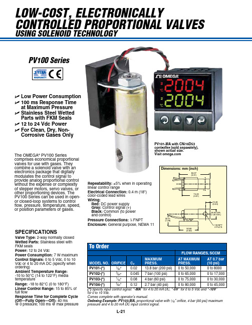
L-21low-cost, electronically controlled proportional valves using solenoid technologyU Low Power ConsumptionU 100 ms Response Time at Maximum PressureU Stainless Steel Wetted Parts with FKM SealsU 12 to 24 Vdc PowerU For Clean, Dry, Non-Corrosive Gases OnlySPECIFICATIONSValve Type: 2-way normally closedWetted Parts: Stainless steel withFKM seals Power: 12 to 24 VdcPower Consumption: 7 W maximumControl Signals: 0 to 5 Vdc, 0 to 10Vdc or 4 to 20 mA DC (specify when ordering)Ambient Temperature Range: -10 to 50°C (14 to 122°F) media temperatureRange: -18 to 82°C (0 to 180°F)Linear Control Range: 15 to 85% offull flow Response Time for Complete Cycle (Off—Fully Open—Off): 40 ms @ 0 pressure; 100 ms @ max pressure The OMEGA ®PV100 Seriescomprises economical proportional valves for use with gases. They combine a solenoid valve with an electronics package that digitally modulates the control signal to provide analog proportional control without the expense or complexity of stepper motors, servo valves, or other proportioning devices. The PV100 Series can be used in open- or closed-loop systems to control flow, pressure, temperature, speed, or position parameters of gases.PV101-MA with CNi16D53 controller (sold separately), shown actual size. Visit for 0 to 10 es complete with operator’s manual.Ordering Example: PV103-MA, proportional valve with 1⁄16" orifice, 4 bar (60 psi) maximumpressure and 4 to 20 mA DC input control signal.Wiring:Red: Gray: Black: Enclosure:pv100 series。
- 1、下载文档前请自行甄别文档内容的完整性,平台不提供额外的编辑、内容补充、找答案等附加服务。
- 2、"仅部分预览"的文档,不可在线预览部分如存在完整性等问题,可反馈申请退款(可完整预览的文档不适用该条件!)。
- 3、如文档侵犯您的权益,请联系客服反馈,我们会尽快为您处理(人工客服工作时间:9:00-18:30)。
修订内容 更改代码 新的封底 添加4页: 应用安全章节 大幅修订 大幅修订
版本号 CD CF DA DB EA
样本修订
PVG产品的样本修订
名称 PVG 32 农机模块-公制油口 PVG 100 比例阀 PVG 120 比例阀 PVBZ 基本模块 PVSK 模块,集成了分流和P口切断功能 PVED-CC 电控模块 PVED-CX 电控模块,系列 4 PVE 系列 4 PVPV / PVPVM 泵侧模块 PVHC 电控模块,用于PVG32和PVG100 PVGI 过渡模块 PVSP/M 优先模块 PVBM “Meter-in” “Meter-out” 模块 类型 产品样本 维修手册 产品样本 产品样本 产品样本 产品样本 产品样本 产品样本 产品样本 产品样本 产品样本 产品样本 样册 代码 11051935 11048807 520L0356 520L0721 520L0556 520L0665 11070179 520L0553 520L0222 11064912 520L0405 520L0291 L1117392
PVG 100 功能
PVG 100 阀组带开芯 PVPF .............................................................................................................................................9 PVG 100 阀组带闭芯 PVPV / PVPVP / PVPVM ....................................................................................................... 11 PVG 100 闭芯转向优先模块 PVPVP ................................................................................................................. 12 PVG 100 闭芯模块 PVPVM ................................................................................................................................... 12 PVG 100 工作模块 PVB ........................................................................................................................................... 12 PVG 100 回油模块 ................................................................................................................................................... 12 负载敏感控制................................................................................................................................................................... 14 远程压力补偿控制 ......................................................................................................................................................... 15 远程压力补偿系统特性: ........................................................................................................................................ 15 典型实例:远程压力补偿系统........................................................................................................................... 15 PVG 100 主阀芯,带压力补偿控制......................................................................................................................... 16 压力补偿系统特性 ................................................................................................................................................... 16 典型实例:压力补偿系统 .................................................................................................................................... 16 PVMR, 摩擦定位 .............................................................................................................................................................. 17 PVMF, 机械浮动位置锁定. ......................................................................................................................................... 17 PVBS, 流量控制主阀芯 (标准)................................................................................................................................. 18 PVBS, 流量控制主阀芯 (线性特性) ............................................................................................................................. 18 安全建立 ............................................................................................................................................................................ 19 FMEA (故障模式及影响分析) IEC EN 61508 ................................................................................................... 19 故障模式及影响分析 ISO 12100-1 / 14121..................................................................................................... 19 实例:控制系统. ........................................................................................................................................................... 20 PVG 100 – LS卸荷或先导油切断可选 ............................................................................................................... 22
MAKING MODERN LIVING POSSIBLE
产品样本
比例阀 PVG 100
产品样ቤተ መጻሕፍቲ ባይዱ 修订版本
修订版本
PVG 100 比例阀
修订日期 2010年1月 2010年12月 2011年9月 2013年3月 2013年8月
页码 14, 17, 41 44 39-42 All All
PVG 100样本中含有带T0通道的模块,更多关于T0通道的内容请见 PVG 32 公制油口, 11051935 和 PVBZ 基本模块, 520L0721.
2
11034399 • EA • Aug 2013
产品样本 内容
概述
PVG 100 比例阀
缩写 .........................................................................................................................................................................................6 概述 .........................................................................................................................................................................................7 阀组系统 .........................................................................................................................................................................7 PVG 100 综合特性, 负载独立的流量控制 ..........................................................................................................7 PVP - 泵侧模块 .............................................................................................................................................................7 PVB – 工作模块 .............................................................................................................................................................8 驱动模块 .........................................................................................................................................................................8 远程控制单元 ...............................................................................................................................................................8