无线加速度节G102使用手册
华测X10GNSS产品使用说明书
10
2 接收机外业工作要求
注意事项: 1 电台模式,基准站脚架和电台鞭装天线脚架之间距离建议>3m 以上, 避免电台干扰卫星信号。 2 基准站应架设在地势较高、视野开阔的地方,避免高压线、变压器等强 磁场,以利于 UHF 无线信号的传输和卫星信号的接收,网络模式还需要注意假 设点的运营商网络覆盖情况。 3 电台模式,若移动站距离较远,还需要增设电台天线加长杆。 4 基准站若是架设在已知点上,要做严格的对中整平。 5 电源线和蓄电池的连接要注意红正黑负,避免短路情况。 6 电台工作时要确保接外接天线,否则长时间工作会导致发送信号被电台 自身吸收而烧坏电台。 7 在连接电缆的时候,注意 Lemo 头红点对红点的连接。 8 采用 GPRS 模式作业,每小时 GPRS 流量在 0.5M-1.5M 左右(与卫星颗 数和网络环境有关)。 基站外挂电台架设图示如下:
电源开关要依次打开; 11 禁止在没有切断电源的情况下对各连线进行插拔; 12 各连接线材破损后请不要再继续使用,应及时购买更换新的线材,避免造
安控科技 无线压力传感器 说明书

无线压力传感器使用手册(第二版)一、 外型二、 主要功能✓自动测量压力值。
✓自带液晶显示器及键盘。
✓远程修改工作参数﹙主动上传数据﹚。
✓锂电池供电。
三、 特点1.设备简单,只有一个与传统压力变送器相似的终端组成。
2.安装方便,与传统的压力变送器安装方法相同。
3.使用方便,自带液晶显示器及按键,可以随时读值及修改参数。
4.运行稳定,使用电池供电,可消除外界电网干扰。
5.技术先进,采用了先进的ZigBee技术。
四、 主要技术指标1.压力测量精度0.5%2.压力测量范围0~25MPa/0~35MPa3.工作温度范围-40 ~ 70℃4.液晶显示温度-20 ~ 50℃5.工作湿度范围 5 ~ 95%6.工作电压 3.6V7.采用IEEE802.15.4通讯模式 2.4GHz多频/多址8.数据传输距离(空旷距离)30米9.最大功耗1mW10.接收灵敏度-100dBm11.重量<1.5kg12.外型尺寸见下图五、 型号说明SZ903测压范围0-25 MPaSZ905测压范围0-35 MPa1六、 安装● 检查无线压力变送器,应无伤痕等异常情况。
● 设置通讯频段,组号,站号。
● 接通电池电源,检查电源灯应闪烁。
● 按照常规压力变送器的安装方法,将该压力变送器安装在井口管线上。
注意:安装和拆卸时,用扳手拧在压力头的六角螺母上,不能直接转动压力变送器外壳,否则容易损坏压力变送器。
仪表显示与按键示意图1. 上电。
接通电池,LED 指示灯先亮3~5秒然后连续快闪10次,并且LCD 全显则程序初始化正确,如不闪烁则为电台初始化不正确需要检查电路,全显一段时间后液晶显示初始界面,电路进入测试状态,大概经过一分半钟后,才进入正常工作状态。
在测试状态时通过手操器可以修改仪表的参数。
2. 在显示压力界面下,长按确认键大概5秒,可从测试状态快速进入正常工作状态,如果在正常工作状态,按此键5秒,也可从正常工作状态,快速进入测试状态,此时的状态可以和手操器进行连接,也可以通过手操器进行以下的设置。
LINK USB无线模拟器控制器使用说明说明书

T urn on the power of the PC and connect the WSC-1 to the USB port of the PC.A setup complete message will be displayed and automatically recognized.Use the link button to link with the transmitter S-FHSS 2.4GHz system to be used.* When operating the link, bring the transmitter within 8 inches.1 Bring the transmitter and the receiver closeChecking WSC-1 on Windows Right-click the game controller icon (WSC-1) and click "Game Controller Settings" in the displayed menu.displayed on the controller (it may be displayed as 8-axis 0 button), and the status is displayed as "OK".Thank you for purchasing the WSC-1 Wireless Simulator Control for S-FHSS 2.4GHz System. This WSC-1 is a USB interface that enables the S-FHSS 2.4GHz system Futaba transmitter to be used wirelessly as a controller for Real Flight RF8 / 9 or later. (The S-FHSS 2.4GHz system Futaba transmitter can also be used as a game controller for Windows ®.)Mini screwdriverLink to the transmitterController settingsClick Settings ...1. Click the mark3. Click [Edit] buttonDisplayed as WSC-1 (Active)2. Click the FutabaClick Select Controller...To use it as a real flight controller, register the Futaba transmitter by following the steps below.Transmitter settingsS-FHSS 2.4GHz system When using the Futaba transmitter as a substitute for the real flight InterLink Controller, set the SW / VR functions of the transmitter after CH5 as shown in the figure.Click ControllerSet the Deadband Percentage (%) number to "0".2 or3 pos SWCH53 pos SW CH82 or3 pos SWCH7VR CH6After making changes to your controller profile, you will want to save all modifications. Note that you cannot make changes to stock profiles that are included with RealFlight. Click the [Save As] button to save the profile under a different name.Input (Example Mode change: Mode 2 to Mode 1)changing the stick movement from mode 2 to mode 1, first change the operating axis of the elevator channel. Channe l 2 -Elevator Click Input at the far right of the display. The Input Detection screen will be displayed. Operate the elevator stick in mode 2 of the transmitter. When the elevator settings are complete, you will be returned to the Edit Profile screen. Then perform the same operation on the throttle side. This completes the mode If you use mixing, dual rate, expo programmed on your radio.Enable Software Radio Mixes ------OFFEnable Software Radio Dual Rates and Expo ------OFF*In this case, SW / VR is not set using the AUX CH (AUX channel) function of the transmitter.*For detailed explanation, please read the instruction manual of RF8 / 9.If you need to change the direction of operation by operating a stick, switch, etc., click the check box of Reverse to add or remove the mark.Calibrationis necessary to calibrate the stick neutral position and operating range of the transmitter with [Calibration]. please read the instruction manual of RF8 / 9.1. Click the [Save As...] button.U n c h e ckand later versions, do not click Input for channels after Channel 7. If you click it, either the smoke ON / OFF switch or the throttle hold switch will not operate. click it, do not save it, close the screen, and try again.ThrottleElevatorMode 1Input Detection screenRF8 Edit ProfileRF9 Edit ProfileReverse:Change the operating directionInput: Change of operation stick, switch, etc.2. Enter a new name.3. Click the [OK] button.。
Futaba10C-10CH中文说明书(1)

项设置或者功能的时候,都包含了大量的解释、描述文字,突出进行该项设置的“目的”、 该功能的“用途”,不像 14 通道或 12 通道设备配备的说明书,大量的篇幅用来说明菜单系 统、屏幕格局。此外,10C 说明书还注重功能设置、数据与和实际动作、设备的紧密联系, 对设置产生的实际效果描述十分清晰。 2. 英文说明书中对屏幕按键的使用方法写得“极为”详细,例如滚轮、导航键的组台使用方法 在几乎存在于每一页的设置举例中,这些表格看起来很复杂,但其实很简单,对于已经使用 过 Futaba9 通道遥控设备的用户,不必每 1 页的操作动作指引都看,按键使用方法与其它的 设备近似。之所以写得如此详细,是为了便于未接触过遥控器的初学者使用。 3. 对于各种类犁飞机、各重要功能项的基本设置原则介绍,是 10C 英文说明书中最“精华”的 内容,引导使用者进行正确的、快速的设置,请初次接触航空模型的用户多多注意,通过阅 读、揣摩,可以学到很多有用知识,本来译者有翻译 14z 说明书的成功先例,以为 10c 的说 明书会相对容易翻译一些,但仔细看过 10c 英文说明书后,即觉得它几乎是一本遥控模型设 置的基本手册,其间不乏模犁技术、原理、应用举倒,有些内容译者自己能理解,但用文字 正确表述出来,让爱好者在实际使用时能明白含义并且设定正确,确实让我们颇费番脑筋。 其中广泛涉及到各种倾斜盘操纵方式的直升机;各种空气动力布局的固定翼(3A 和滑翔机) 各种尾翼的操纵形式,让我们在翻译说明书的同时,对相对应的空气动力知识进行补充学习, 这个过程对我们自身的专业知识也是一个促进和提高。 4. 不同功能之间的关联性描述得十分清楚。例如在解释一项舵面混控功能之后,会列出与之相 关的多个混控项,并给出页码。 5. 不仅说明书正文通俗易懂,而且说明书的最后附有名词解释(专业词汇表),这也是其“贴 心”设计的重要表现。对文字理解有困难的用户可以用作参考。
骏晔科技-DL-S24G-102-微波人体感应传感器-使用说明书

24G新型微波传感模组说明书产品名称: 微波人体感应传感器 产品型号:DL-S24G-102文件版本号:V1.1使用本模块产品前,注意以下重要事项:仔细阅读本说明文档本模块属于静电敏感产品,安装测试时请在防静电工作台上进行操作。
本模块默认使用外接天线,天线可选用导线天线或者标准的UHF天线,具体天 线的客户请根据实际情况进行选择,如果所应用的终端产品是金属外壳,请务 必把天线安装于金属外壳之外,否则会导致射频信号严重衰减,影响有效使用距离。
金属物体及导线等应尽量远离天线。
安装模块时,附近的物体应保证跟模块保持足够的安全距离,以防短路损坏。
绝不允许任何液体物质接触到本模块,本模块应在干爽的环境中使用。
使用独立的稳压电路给本模块供电,避免与其他电路共用,供电电压的误差不应大于5%。
局限性说明:本模块是为了嵌入到客户的终端产品应用,本身并不提供外壳,不建议客户未经允许的情况下直接把本模块作为最终产品批量转售。
本系列模块各项指标符合常用的国际认证,客户应用本模块的产品如需通过某 些特殊认证,我司会根据客户的需求对某些指标进行调整。
本模块不可应用于生命救助,生命保障系统,以及一切由于设备故障会导致人 身伤害或生命危险的场合,任何组织或个人开展上述应用需自行承担一切风险, 骏晔科技不承担任何连带相关的责任。
骏晔科技不承担任何应用了本模块的产品所引起的直接或间接造 成的破坏,伤害,利益损失。
文件版本更新管理日期 软件版本 说明2016-8-5 标准版本V1.0 标准版本2018-5-20 升级版本V1.1模块介绍1、特点简介DL-S24G是一款多普勒微波感应器。
其拥有适用性极强的平面微带微波天线及微小的功耗,在近距离探测目标的移动及智能控制方面得到广泛的应用,高性能微波器件及专业工艺制程控制,结合行业深度应用的软件算法使我们的微波传感模块一直保持着独特的技术优势与品质保障。
模块组件大大缩短项目研发周期、提高产品量产一致性。
首先感谢您选择购买并使用本产品

声明首先感谢您选择购买并使用本产品,为了您能够更好的使用本产品的所有功能,请您在正式使用本产品前仔细阅读本手册内所提及的在产品使用过程中应注意的事项以及详细功能操作说明。
本手册内所描述之产品组件已申请并注册国家专利,任何仿冒均属侵权行为,须承担牵连之法律责任。
本产品组件符合国家低压电子产品安全标准。
本产品机身及包装盒标贴的专有系列号码标签是产品保修时的重要凭证,当产品需要保修时,用户需出示产品的系列号条码标签。
如果该标签遭到破坏,无法辨认或撕毁,本公司将不予保修。
本产品享有三个月保换,两年免费保修的售后服务。
并非所有的使用环境都适合本产品的使用;本公司仅对产品本身质量按照本公司承诺的保修条款提供售后服务,但对由于使用本产品导致的数据资料损失,或者其它相关责任,本公司不予负责。
因为技术上或者其他外部因素导致本产品设计规格上的变更,本公司将不再另行单独通知。
免除义务条款1.本公司对因地震、雷电等自然灾害、不是因为本公司的责任而发生的火灾、第三方操作、失盗、损坏、意外事故因在不正常情况下使用(如不正常的操作、误操作或其他问题)引起的损失不承担任何责任。
2.本公司对因使用本产品或不能使用本产品而带来的损失(利润损失、工作中断等)不承担任何责任。
3.本公司对因未遵守本使用说明书而引起的任何损失不承担任何责任。
4.本公司对因与本公司无关的设备或软件结合使用而引起的故障造成的任何损失不承担任何责任。
5.本公司对磁盘的损坏以及数据的丢失不承担任何法律责任6.本公司对软件使用界面与实际产品不符合、软件BUG未及时升级、说明书内容、光盘内容等与实际产品不符甚至不能操作,主机按键标识或者遥控器的按键标识与实际有误等不承担任何有关法律的责任。
商标NOONTEC为本公司专有之使用商标。
本使用说明书内涉及的所有其他商标或者产品名称,皆为本公司的商标或注册商标。
安全注意事项本产品的设计与制造充分考虑了使用的便利与人体的安全性能等问题,任何不妥当的使用都可能会引起不必要的麻烦与损失。
博联科技 短距离WSN采集节点系列BLM2100D(开关量)说明书

短距离WSN采集节点系列BLM2100D(开关量)__________________________________________________________用户手册苏州博联科技有限公司江苏省苏州市工业园区林泉街399号邮编:215123电话**************/2/3传真:*************网址:目录第一章产品概述 (3)1.1 概述 (3)1.2系统功能与特点 (4)1.3产品图片 (4)1.4典型应用示意图: (4)第二章规格型号 (6)2.1产品尺寸 (6)2.2性能指标 (6)2.3射频参数 (6)2.4网络性能 (7)第三章安装指南 (8)3.1采集点及其配件 (8)第四章通信协议 (9)第一章产品概述本章概要介绍短距离无线数据终端产品—无线门开关信号采集节点BLM2100D的结构、特点、工作原理等。
1.1 概述无线传感器网络是新一代的传感器网络,具有非常广泛的应用前景,其发展和应用,将会给人类的生活和生产的各个领域带来深远影响。
无线传感器网络技术是一种应用于短距离、低传输数据速率下的电子设备之间的无线通信技术。
具有功耗低、数据传输可靠、网络容量大、兼容性好、安全性、实现成本低等特点。
苏州博联科技出品的无线门开关信号采集节点BLM2100D,采用了最新无线传感器网络技术,符合工业标准应用的无线数据通信设备,包括无线门开关传感器A和无线门开关传感器B,每间隔5秒采集一次开关信号,当A和B相距3cm范围内时,为关闭信号,当二者超出此范围时,为打开信号。
无线开关门传感器A可以将检测到的开关门信号数据转换成电信号,并经发射模块通过无线方式发送出去。
该产品由苏州博联科技自主研发,提供快速完善的产品技术支持和定制服务,我们还可以协助用户进行系统设计,提供组网服务。
产品具有优良的数据传输可靠性和广泛的适用性,是各行业专用数据通信系统理想的选择。
本说明书将为您更好地使用无线门开关信号采集节点BLM2100D提供帮助。
霍比路由器配置指南说明书
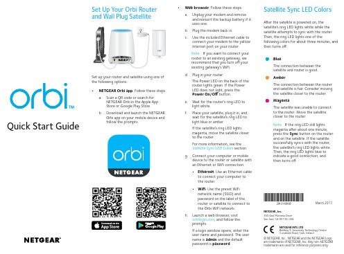
a. Place your Orbi satellites in opposite corners of your house, but still within range of theOrbi router.If your house has multiple floors, place your Orbi satellites on different floors.b. Connect an Orbi satellite to a power source.The Power LED on the back of the Orbi satellite lights green. If the Power LED does not light, press the Power On/Off button.The Orbi satellite’s ring LED lights white while the satellite attempts to sync with the Orbi router.2. Place Your Orbi Satellites (Continued)Orbi router Orbi satelliteOrbi satellite After the Orbi satellite’s ring LED lights white, it lights one of the following colors for about three minutes and then turns off:BlueThe connection between the Orbi router and Orbi satellite is good.AmberThe connection between the Orbi router and Orbi satellite is fair. Consider movingthe Orbi satellite closer to the Orbi router.MagentaThe Orbi satellite was unable to connect to the Orbi router. Move the Orbi satellitecloser to the Orbi router.Note: If the ring LED still lights magenta after about one minute, press the Syncbutton on the back of the Orbi router and on the back of the Orbi satellite. If the Orbi satellite successfully syncs with the Orbi router, the satellite’s ring LED lights whitethen lights blue to indicate a good connection, and then turns off.a. Connect your computer or mobile device to the Orbi router or satellites with anEthernet or WiFi connection:• Ethernet. Use an Ethernet cable to connect your computer to the Orbi router or satellites.• WiFi. Use the preassigned WiFi network name (SSID) and password on the label of the Orbi router or satellites to connect to the Orbi WiFi network.b. Set up your network using one of the following options:• NETGEAR Orbi app. Download the NETGEAR Orbi app on your mobile device. You can scan a QR code on the other side of this quick start guide to get the app. Launch the app and follow the onscreen instructions.• Web browser. Launch a web browser and visit . If a login window opens, enter the user name and password. The user name is admin and the defaultpassword is password. Follow the onscreen instructions.The Orbi router’s ring LED turns off after the setup is complete.SupportThank you for purchasing this NETGEAR product. You can visit/support to register your product, get help, access the latest downloads and user manuals, and join our community. We recommend that you use only official NETGEAR support resources.For the current EU Declaration of Conformity, visit/app/answers/detail/a_id/11621/.For regulatory compliance information, visit /about/regulatory/.See the regulatory compliance document before connecting the power supply.NETGEAR INTL LTDBuilding 3, University Technology CentreCurraheen Road, Cork, IrelandNETGEAR, Inc.350 East Plumeria Drive San Jose, CA 95134, USA© NETGEAR, Inc., NETGEAR and the NETGEAR Logo are trademarks of NETGEAR, Inc. Any non‑NETGEAR trademarks are used for reference purposes only.December 2016Orbi router (Model RBR50)Orbi satellites (2)(Model RBS50)Ethernet cablePower adapters (3)Ring LED (not shown in image)Sync button (also used for WPS connection)Internet port (the Orbi satellite does not include an Internet port)Ethernet ports2134128218USB portPower On/Off button and Power LED DC Power connector Reset button5678Download the NETGEAR Orbi AppUse the NETGEAR Orbi app to set up and manage your network. To find the app, scan one of the following QR codes or search for NETGEAR Orbi in the Apple App Store or Google Play Store.。
海伍伊无线加速器说明书

MOBILE DEVICE STORAGEData SheetSeagate Wireless Plus, mobile storage you can access withoutwires or WebWith Seagate® Wireless Plus, you can enjoy your media and access your fileswithout wires or the Internet. This mobile storage device broadcasts its ownWi-Fi network, so you can wirelessly stream your media and files to your tabletor smartphone on-the-go and off-the-grid. You can even bring your files storedon Dropbox® or Google Drive with you. Easily synchronize your cloud files to yourWireless Plus and access them even when you are not connected to the Internet.The free Seagate Media app available for iOS, Android® tablets and smartphones,Kindle Fire and Windows® 8|RT, tablets and computers makes it easy to navigateand enjoy content wherever you go.Forget about having to choose which files to load onto your tablet or smartphonebefore a trip. Bring it all with you! Wireless Plus comes with 500GB, 1TB or 2TB ofbuilt-in storage, which means you can load hundreds of movies or thousands ofsongs, photos and documents.1 Simply drag-and-drop to load files wirelesslyfrom your PC or Mac® computer or use the USB 3.0 adapter to load files up to10× faster than Wi-Fi N.Wireless Plus allows up to eight tablets and smartphones to access and storecontent at the same time. Leave it in your bag, set it on the table, place itanywhere in the car—with a range of up to 150 ft, you’ll never feel tethered toyour storage. Best of all, by creating its own Wi-Fi network, there is no need for anInternet connection, and you don’t have to use your data plan.1 Quantitative usage examples for various applications are for illustrative purposes. Actual quantities will vary based on factors,including file size, file format, features and application software.AMERICAS Seagate Technology LLC 10200 South De Anza Boulevard, Cupertino, California 95014, United States, 408-658-1000 ASIA/PACIFIC Seagate Singapore International Headquarters Pte. Ltd. 7000 Ang Mo Kio Avenue 5, Singapore 569877, 65-6485-3888 EUROPE, MIDDLE EAST AND AFRICASeagate Technology SAS 16–18, rue du Dôme, 92100 Boulogne-Billancourt, France, 33 1-4186 10 00© 2014 Seagate Technology LLC. All rights reserved. Seagate, Seagate Technology and the Wave logo are registered trademarks of Seagate Technology LLC in the United States and/or other countries. All other trademarks or registered trademarks are the property of their respective owners. When referring to drive capacity, one gigabyte, or GB, equals one billion bytes and one terabyte, or TB, equals one trillion bytes. Your computer’s operating system may use a different standard of measurement and report a lower capacity. In addition, some of the listed capacity is used for formatting and other functions, and thus will not be available for data storage. Quantitative usage examples for various applications are for illustrative purposes. Actual quantities will vary based on various factors, including file size, file format, features and application software. Complying with all applicable copyright laws is the responsibility of the user. Exact battery life subject to product model, normal usage conditions and configurations. Dispose of used batteries properly. Seagatereserves the right to change, without notice, product offerings or specifications. DS1771.2a 1406 APAC1 One gigabyte, or GB, equals one billion bytes and one terabyte, or TB, equals one thousand billion bytes when referring to drive capacity.Navigating your media library is simple with the Seagate Media app. Sort through large media libraries with cover art, metadata, filters, keyword search, folder and media views. Download movies and other media to your device, so you can enjoy your content later, when not connected to Wireless Plus. When you need more storage capacity on your smartphone or tablet, you can easily off-load photos and videos from your device’s camera roll by uploading them to your Wireless Plus storage device using the Seagate Media app.At home, Wireless Plus can stream media to your TV too. Game consoles, smart TVs, connected Blu-ray players and other DLNA devices can access the content on Wireless Pluswhenever you have it connected to your home network via Wi-Fi. If you have an Apple TV ®, your iPad, iPhone and iPod touch can use AirPlay ® to take your media from small screen to big screen. Additionally, with Samsung Smart TVs, Blu-ray players and select streaming players, you can directly install the Seagate Media app and experience your content with an interface optimized for living room viewing and easy remote-control navigation.MOBILE DEVICE STORAGE。
HOBBYWING XR10 Justock 高性能传感器无线电速控器用户手册说明书
01Introduction03Features02Warnings04Specifications05Connections06ESC SetupESC/Radio CalibrationThank you for purchasing the XR10 Justock, HOBBYWING’s highperformance sensorless brushless motor electronic speed controller! Brushless power systems can be very dangerous. Any improper use may 1USER MANUALXERUN XR10 JustockBrushless Electronic Speed Controller• Compact design for easy installation.• Compatible with sensored/sensorless brushless motors. In sensored mode, it’s compatible with most popular sensored brushless motors on the market. In sensorless mode, it’s compatible with 99% of brushless motors on the market.• Aluminum housing top with excellent heat dissipation and great current endurance.• The timing has been permanently set to 0 degree. With the identical competition motor, this ensures that every driver will have the same power system and have a really just STOCK race. • Proportional brake with 4 steps of maximum brake force, 8 steps of drag brake force and 4 steps of initial brake force.• 9 levels of acceleration/ punch from “soft” to “aggressive” for different vehicles, tires and tracks.• Multiple protections: motor lock-up protection, low-voltage cutoff protection, thermal protection and fail safe (throttle signal loss protection).• Single-button ESC programming and factory reset.• Advanced programming via portable LED program card or multifunction LCD program box.• Firmware upgrade via HOBBYWING multifunction LCD program box (item sold separately).1. Motor WiringThe sensored motor wiring is a little different from the sensorless motor wiring; please make sure that you will strictly follow the introductions below. A. Sensored Motor WiringThere is strict wiring order from the ESC to the motor, the three A/B/C ESC wires must connect to the three A/B/C motor wires correspondingly and then connect the ESC sensor port and the motor sensor port with the stock 6-pin sensor cable.Note 1: If you don’t plug the sensor cable in, your ESC will still work in sensorless mode even if you’re using a sensored motor. B. Sensorless Motor WiringThere is no polarity on the A/B/C wires between ESC and motor, so do not worry about how you connect them initially. You may find it necessary to swap two wires if the motor runs in reverse. 2. Receiver WiringPlug the throttle control cable (also called Rx cable) on the ESC into the throttle (TH) channel on receiver. The red wire in the throttle control cable will output the BEC voltage of 6V to the receiver and servo, so please do not connect any additional battery to the receiver. Otherwise, your ESC may be damaged.3. Battery WiringProper polarity is essential here! Make absolutely sure positive (+) of ESC connects to positive (+) of battery, and negative (-) of ESC connects to negative (-) of battery when you plug in your battery! If reverse polarity is applied to your ESC from the battery, it will damage your ESC. This will not be covered under warranty!In order to make the ESC match the throttle range, you must calibrate it when you begin to use a new ESC, or a new transmitter, or after you change the settings such as the TRIM, D/R, EPA Warning Tones2Turn on the ESC in the normal way (that is to turn it on without holding the SET button); the motor will beep the number of LiPo cells you have plugged in. For example, 2 beeps indicate a 2S LiPo, 3 beeps indicate a 3S LiPo.Programmable Items3(Those "black backgroud and white text" options are the factory default settings)1. Running ModeOption 1: Forward with BrakeThe vehicle can go forward and brake but cannot reverse in this mode. This mode is usually for racing. Option 2: Forward/Reverse with BrakeThis mode provides the braking function, it’s usually for training. “Forward/Reverse with Brake” mode adopted the “DOUBLE-CLICK” method, that is your vehicle only brakes (won’t reverse) when the 1st time you push the throttle trigger forward (away from you) (1st push). If the motor stops when you quickly release the throttle trigger and then re-push the trigger quickly (2nd push), the vehicle will reverse. If the motor does not stop, then your vehicle won’t reverse but brake, you need to push the throttle trigger one more time. The vehicle only reverses after the motor stops. This method is for preventing vehicle from being accidentally reversed. Option 3: Forward/ReverseThis mode used the “SINGLE-CLICK” method to make the car go backward. When you move the throttle trigger from forward zone to backward zone, the car will go backward immediately. This mode is usually used by special vehicles like the rock crawler.2. Drag Brake ForceDrag brake is the braking power produced when releasing the throttle trigger to neutral zone. This is to simulate the slight braking effect of a neutral brushed motor while coasting. (Attention! Drag brake will consume much power, so please apply it cautiously.)3. Cutoff Voltage (or Low Voltage Cutoff Threshold)Sets the voltage at which the ESC lowers or removes power to the motor in order to keep the LiPo battery at a safe minimum voltage. The ESC will monitor the battery voltage all the time, it will gradually reduce the power to 30% in 3 seconds (at this time, racer should pull the car aside and drop out of the race immediately to avoid blocking the track or hitting by some car comes behind.) and cutoff the output 10 seconds later when the voltage goes below the cutoff threshold. The RED LED will flash a short, single flash that repeats (☆-, ☆-, ☆-) to indicate the low-voltage cutoff protection is activated. If necessary, you can customize the cutoff voltage at the precise step of ±0.1V through a multifunction LCD program box (item sold separately)for different battery packs like NiMH, LiFe and etc. 4. Start Mode / Punch /AccelerationYou can choose the punch from level 1 (very soft) to level 9 (very aggressive) as per the track, tires, grip, your preference and etc. This feature is very useful for preventing tires from slipping in the starting-up process. In addition, “level 7”, “level 8 and “level 9” have strict requirement on battery’s discharge capability. It may affect the starting-up if the battery discharges poorly and cannot provide large current in a short time. The car stutters or suddenly loses power in the starting-up process indicating the battery’s discharge capability is not good; you need toreduce the punch or increase the FDR (Final Drive Ratio).5. Brake Amount/ Max. Brake ForceThis ESC provides the proportional braking function; the braking effect is determined by the position of the throttle trigger. It sets what percentage of available braking power is applied with full brake. Large amount will shorten the braking time but it may damage your pinion and spur. Please select the most suitable brake amount as per your car condition and your preference.6. Reverse Amount/ Max. Reverse ForceDifferent reverse amount will bring different reversing speed. For the safety of your vehicle, we recommend using a low amount.7. Maximum Reverse Force:Sets how much power will be applied in the reverse direction. Different value makes different reverse speed. 8. Throttle Neutral RangeAdjust the throttle neutral zone as per your preference (as shown). Because the neutral position on some transmitters is not stable and it can cause the vehicle to go forward/backward slowly, so please set the throttle neutral width to a bigger value when this issue happens. 9. Timing:This item has been permanently set to “0” degree. 10. Overheat Protection:If this item is activated, the output will be automatically cut off when the ESC temperature or the internal temperature of the sensored brushless motor goes above the factory preset value. The Green LED will flash when this protection is activated. The output won’t resume until the ESC/motor cools down. When the ESC is overheated, the Green LED will flash a short, single flash that repeats “☆-, ☆-, ☆-”.When the motor is overheated, the Green LED will flash a short, double flash that repeats “☆-☆-, ☆-☆-, ☆-☆-”.Note: The motor overheat protection is only available to the sensored brushless motor manufactured by the same manufacturer of this ESC. For motors made by other manufacturers, this function may not be available or the protection point doesn’t match the design of the ESC, please disable the overheat protection in this case.(For more information, please refer to the user manual of the LCD program box.)You can program this ESC through a 3-in-1 LCD program box or through a 3-in-1 LCD program box and a PC (HOBBYWING USB LINK software needs to be installed on the PC). Before theprogramming, you need to unplug the throttle control cable (or Rx cable) from the receiver and plug it into the programming/ESC port on the program box, then the boot screen will show up on the LCD, press any button on the program box to initiate the communication between your ESC and the program box,. The “CONNECTING ESC” will be displayed, a few seconds later; the program box will display the current mode like profile 1 and then the 1st programmable item like running mode. You can adjust the setting through “ITEM” & “VALUE” buttons, and then press the “OK” button to save new settings to your ESC.07Explanations for Different Status LEDs08Trouble ShootingFactory Reset5• Restore the default values with the SET buttonPress and hold the SET button for over 3 seconds anytime when the throttle trigger is at the neutral position (except during the ESC calibration and programming) can factory reset your ESC. RED & GREEN LEDs flash simultaneously indicating you have successfully restored all the default values within your ESC. Once you power the ESC off, and then back on, your settings will be back in the default mode.• Restore the default values with the LED program boxAfter connecting the program box to the ESC, press the “RESET” button and the “OK” button to factory reset your ESC.• Restore the default values with a multifunction LCD program boxAfter connecting the program box to the ESC, continuously press the “ITEM” button on the program box until you see the “RESTORE DEFAULT” item, and then press “OK” to factory reset your ESC.1. During the Start-up Process• The GREEN LED flashes “N” times indicating the number of LiPo cells you have connected to the ESC.2. In Operation• The RED LED flashes rapidly when the throttle trigger is in the throttle neutral zone.• The RED LED turns on solid when your vehicle runs forward. The GREEN LED will also come on when pulling the throttle trigger to the full (100%) throttle endpoint.• The RED LED turns on solid when you brake your vehicle. The GREEN LED will also come on when pushing the throttle trigger to the full brake endpoint and setting the “brake amount/maximum brake force” to 100%.• The RED LED turns on solid when you reverse your vehicle.3. Some Protection is Activated• The RED LED flashes a short, single flash that repeats (☆-, ☆-, ☆-) indicating the low voltage cutoff protection is activated. • The GREEN LED flashes a short, single flash that repeats (☆-, ☆-, ☆-) indicating the ESC thermal / overheat protection is activated. • The GREEN LED flashes a short, double flash that repeats (☆☆-, ☆☆-, ☆☆-) indicating the motor thermal /overheat protection is activated.Trouble(s)Solution(s)Possible Causes1. No power was supplied to the ESC.2. The ESC switch was damaged.1. Check if all ESC & battery connectors have been well soldered or firmly connected.The ESC was unable to start the status LED, the motor, and thecooling fan after it was powered on.• Ensure all wires and connections are well insulated before connecting the ESC to related devices, as short circuit will damage your ESC.• Ensure all devices are well connected, in order to prevent poor connections that may cause your vehicle to lose control or other unpredictable issues like damage to the device.• Read through the manuals of all power devices and chassis and ensure the power configuration is rational before using this unit. • Please use a soldering iron with the power of at least 50W to solder all input/output wires and connectors.• Stop using the ESC when its casing temperature exceeds 90℃/194℉; otherwise your ESC will get destroyed and may also get your motor damaged.• Always disconnect and remove batteries after use, as the ESC will continue to consume current if it’s still connected to batteries (even if the ESC is turned off). Long-time contact will cause batteries to completely discharge and result in damage to batteries or ESC or both. This will not be covered under warranty.)20170109。
1024说明书

1024说明书1024 DMX控制器⽤户⼿册⽬录1综述1.1功能描述1.2规格参数2安装2.1设备与附件2.2注意事项2.3连接灯具3操作使⽤3.1⾯板图3.2常⽤词汇介绍4配接4.1创建4.1.1配接常规灯4.1.2配接电脑灯4.1.3查看配接信息4.2编辑4.2.1重新配接灯具地址码4.2.2删除配接4.2.3灯具参数5控制灯具5.1灯具的选择与反选5.2修改属性值5.3灯具区推杆功能的切换5.4电脑灯的⾼级控制5.5扇形6图形⽣成器6.1图形调⽤6.2图形编辑6.3图形删除6.4改变图形运⾏⽅向6.5重演参数7单步场景7.1创建7.2导⼊7.3复制7.4删除7.5时间7.6运⾏8多步场景8.1创建8.2删除步8.3步时间8.4导⼊步8.5全局时间8.6删除场景8.7复制场景8.8运⾏8.9连接8.10⾼级控制选项9素材9.1存储素材9.2调⽤素材9.3删除素材10设置10.1擦除重演数据10.2擦除所有数据10.3语⾔切换11升级12灯库编辑器1综述1.1功能描述1024 电脑灯光控制台可同时控制96台电脑灯。
读取珍珠R20格式灯库,内置⼏⼗种图形效果,能同时运⾏10个场景、执⾏5个内置图形,可使⽤推杆运⾏场景并调整场景的调光通道的亮度等级。
1.2规格参数2安装1.1设备与附件产品包装箱内物件清单:1024 电脑灯控台1台电源线⼀条选配:航空箱鹅颈灯U盘1.2注意事项务必使⽤12V的电源适配器请注意防潮防尘1.3连接灯具控台台后板有4个DMX512 输出信号卡侬座,两个为三芯XLR 结构,另两个位五芯XLR结构。
卡侬座的1 脚为信号地线,2 脚为信号负端,3 脚为信号正端。
DMX512 连接电缆采⽤屏蔽式双绞电缆。
电缆的两端需⾃⾏焊接XLR 插头,屏蔽⽹接XLR 插头的第1 脚,双绞线(由不同颜⾊区分)则分别连接XLR 插头的2、3 脚,切勿反接。
插座引⼊脚编号电缆芯线1屏蔽⽹层2信号负端3信号正端3.操作使⽤3.1⾯板图该控台主要由若⼲个区组成:灯具区:由16个灯具键、16根预置推杆和6个灯具换页键组成。
雷兹COBRA Pro无线游戏滑鼠进阶指南说明书

RAZER COBRA PRO進階指南具備 Razer Chroma™ RGB 功能的無線遊戲滑鼠Razer Cobra Pro助你輕鬆迎戰,技驚四座。
搭載 Razer™ HyperSpeed Wireless 及 11 個可個別編程的發光區域,讓你自由設定燈光效果,享受更具沉浸感的遊戲體驗。
目录1. 內含 (3)2. 使用需求 (4)3. 註冊即可享有保固 (5)4. 技術規格 (6)5. 設定你的 RAZER COBRA PRO (7)6. 使用滑鼠 (11)7. 透過 RAZER SYNAPSE 設定你的 RAZER COBRA PRO (13)8. 安全與保養 (31)9. 法律條文 (33)1. 內含▪Razer Cobra ProA.滑鼠左鍵B.滑鼠右鍵C.滾輪D.DPI 分段調升按鍵*E.DPI 分段調降按鈕*F.滑鼠按鍵 5G.滑鼠按鍵 4B Type C 連接埠I.PTFE 材質滑鼠腳J.設定檔指示燈K.設定檔切換鍵L.Razer™ Focus Pro 30K 光學感測器M.滑桿開關•藍牙模式•電源關閉模式•Razer™ HyperSpeed Wireless(2.4 GHz) 模式N.無線傳輸器收納槽 / 蓋板***DPI 分段為 400、800、1600(預設)、3200 及 6400,並可使用 Razer Synapse 自訂。
**可替換為 Razer Wireless Charging Puck,以透過Razer Mouse Dock Pro 進行無線充電(皆需另外購買)。
▪Razer HyperSpeed Wireless Dongle + USB 傳輸轉接器▪USB Type A 轉 USB Type C Speedflex 纜線▪重要產品資訊指南2. 使用需求產品需求▪USB Type A 連接埠或藍牙連線功能RAZER SYNAPSE 需求▪Windows® 10 64 位元(或更新版本)▪網際網路連線(供下載安裝軟體)3. 註冊即可享有保固產品序號標示於此處。
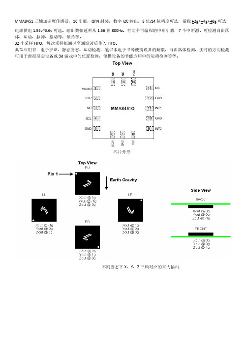
MMA845x_加速度、倾角传感器中文操作手册
2、XYZ_DATA_CFG Register
地址:0x0E,读/写
功能说明:用于配置高通输出数据以及量程设定
Bit7
Bit6
Bit5
Bit4
Bit3
0
0
0
HPF_OU
0
T
0
0
0
0
0
Bit2
Bit1
0
FS1
0
1
Bit0 FS0
0
HPF_OUT: 1:使能高通输出数据 0:关闭高通输出数据 FS[1:0]: 00:2g 01:4g 10:8g 11:待定
芯片外形
不同姿态下 X、Y、Z 三轴对应的重力输出
典型连接
引脚定义如下:
引脚编号 引脚名称
引脚描述
1
VDDIO
内部电源供电(1.62~3.6v)
2
BYP
旁路电容
3
NC
悬空引脚
4
SCL
I2C 串行时钟
5
GND
接地
6
SDA
I2C 串行数据
7
SA0
I2C 最低有效位地址
8
NC
悬空引脚
9
INT2
中断请求引脚 2
1、INT_SOURCE: System Interrupt Status Register
地址:0x0C,只读,
功能说明:用于获取当前中断源
Bit7
Bit6
Bit5
Bit4
Bit3
Bit2
Bit1
Bit0
SRC_ASLP
0
SRC_TRA SRC_LND SRC_PUL SRC_FF_
0
SRC_DRD
罗技 B175 M185 M186 M220 M221 无线鼠标使用说明书
B175 - M185/M186/M220/M221 Setup Guide · 設定指南 · 설치 설명서 · 设置指南LANGUAGESEnglish 5繁体中文 6한국어7简体中文 83© 2016 Logitech Logitech, Logi and other Logitech marks are owned by Logitech and may be registeredAll other trademarks are the property of their respective owners Logitech assumes no responsibility for any errorsthat may appear in this manual Information contained herein is subject to change without notice版權所有 © 2016 年羅技。
羅技、Logi 和其他羅技商標均歸羅技所有,並或已註冊所有其他商標均是其各自所有人的財產。
羅技對於本手冊中可能出現的任何錯誤不承擔任何責任。
手冊內容如有更改,恕不另行通知。
© 2016 Logitech Logitech, Logi 및기타 Logitech 상표는 Logitech의소유이며등록상표일수있습니다그밖의모든상표는해당소유자의자산입니다 Logitech은이설명서에명시된어떤오류에대해서도책임지지않습니다이설명서에있는정보는예고없이변경될수있습니다版权所有 © 2016 年罗技。
罗技、Logi 和其他罗技商标均归罗技所有,并或已注册。
所有其它商标均是其各自所有者的财产。
罗技对于本手册中可能出现的任何错误不承担任何责任。
本手册中包含的信息如有更改,恕不事先通知。
621-000025 002。
WG102用户指南中文操作手册_2009
WG102中文操作指南NETGEARWG102用户指南2009年5月目录1引言 (4)1.1NETGEAR公司概况 (4)1.2WG102介绍 (5)1.2.1产品介绍 (5)1.2.2特性介绍 (5)2硬件描述 (6)2.1前面板 (6)2.2后面板 (7)3基本安装和配置 (8)3.1观察放置和范围指南 (8)3.2安装WG102接入点 (10)3.3怎样使用默认IP地址登录WG102 (13)3.4基本IP设置 (14)3.5基本无线设置 (15)3.5.1配置802.11a无线设置 (15)3.5.2配置802.11b/g无线设置 (16)3.6了解WG102无线安全选项.................................................................. 错误!未定义书签。
3.7配置安全概要 (18)3.7.1(Profile)配置文件定义 (19)3.7.2网络认证 (19)3.7.3数据加密 (20)3.7.4无线客户端的安全隔离 (20)3.7.5VLAN ID (21)3.7.6SSID和无线安全设置表格 (21)3.8配置RADIUS服务器 (22)3.9怎样根据MAC地址限定无线接入 (23)4管理和信息 (24)4.1改变管理员口令 (24)4.2远程管理 (24)4.3升级无线接入点软件 (25)4.4配置文件管理 (26)4.4.1保存和检索配置 (27)4.4.2把WG102恢复到出厂默认设置 (27)4.4.3使用复位按钮恢复出厂默认设置 (27)4.5查看一般信息 (28)4.6查看S YSLOG和活动日志信息 (30)4.7查看相连设备列表 (30)4.8查看统计信息 (31)5高级配置 (32)5.1无线客户端配置高级IP设置 (32)5.2配置热点设置 (34)5.3高级无线设置 (34)5.4无线桥接和中继 (34)5.4.1点对点桥接配置 (35)5.4.2多点桥配置 (36)5.4.3中继模式 (38)6WG102技术参数 (39)1 引言1.1NETGEAR公司概况全球中小规模网络与无线网络的先驱和领导者美国网件(NETGEAR)于1996年1月创立,长期致力于为中小规模企业用户与SOHO用户提供简便易用并具有强大功能的网络综合解决方案。
SDS1000X-C数字示波器快速指南说明书

SDS1000X-C 数字示波器快速指南了解下列安全性预防措施,以避免人身伤害,并防止本产品或与其相连接的任何其它产品受到损坏。
为了避免可能发生的危险,请务必按照规定使用本产品。
使用适当的电源线--只允许使用所在国家认可的本产品专用电源线。
将产品接地--本产品通过电源电缆的保护接地线接地。
为了防止电击,在连接本产品的任何输入或输出端之前,请务必将本产品正确接地。
正确连接信号线--信号线与地电势相同,请勿将地线连至高电压。
查看所有终端额定值--为了避免火灾或电击,请查看本产品的所有额定值和标记说明。
请在连接产品前阅读产品手册,以便了解有关额定值的详细信息。
使用合适的过压保护--确保没有过电压(如由雷电造成的电压)到达该产品,否则可能导致操作人员遭受电击。
防静电保护--静电会造成仪器损坏,应尽可能在防静电区进行测试。
连接电缆到仪器前,应将其内外导体短暂接地以释放静电。
保持良好的通风 --通风不当会引起仪器温度升高,进而引起仪器损坏。
使用时应保持良好的通风,定期检查通风口和风扇。
避免电路外露 --电源接通后,请勿接触外露的接头和元件。
请勿开盖操作--请勿在仪器机箱打开时运行本产品。
使用合适的保险丝 --只允许使用本产品指定规格的保险丝。
请勿在潮湿或易燃易爆的环境下操作注意搬运安全 --为避免仪器在搬运时滑落,造成仪器面板上的按键、旋钮或接口等部件损坏,请在搬运仪器的过程中注意安全。
怀疑产品出故障时,请勿操作 --如怀疑产品有故障,请联系SIGLENT授权的维修人员进行检测。
任何对于本产品的维护、调整或零件更换必须由SIGLENT授权的维修人员执行。
SDS1000X-C 快速指南-IIIII-SDS1000X-C 快速指南本产品上可能出现如下标记:安全术语和标记本产品上使用的术语 本产品上会出现如下术语:-DANGER:表示标记附近有直接伤害危险存在。
-WARNING:表示标记附近有潜在的伤害危险。
-CAUTION:表示对本产品及其他财产有潜在的危险。
网易讯《快速启用指南蓝色版》说明书
For regulatory compliance information, visit /about/regulatory/.
For more information, see the Satellite Sync LED Colors section.
g. Connect your computer or mobile device to the router or satellite with an Ethernet or WiFi connection:
• Web browser. Follow these steps:
a. Unplug your modem and remove and reinsert the backup battery if it uses one.
b. Plug the modem back in.
c. Use the included Ethernet cable to connect your modem to the yellow Internet port on your router.
Satellite Sync LED Colors
After the satellite is powered on, the satellite’s ring LED lights white while the satellite attempts to sync with the router. Then, the ring LED lights one of the following colors for about three minutes, and then turns off:
华测X10GNSS产品使用说明书
成不必要的伤害; 13 各连接线材破损后请不要再继续使用,请及时购买更换新的线材,避免造
成不必要的伤害; 14 对中杆破损后应及时维修、更换,不得残次使用; 15 对中杆尖部容易伤人,使用棒状天线和对中杆时,注意安全。
相关信息
您可以通过以下途径找到该说明书: 1、购买华测 X10 产品后,仪器箱里会配赠一本《华测 X10GNSS 产品使用 说明书》,方便您操作仪器。 2、登陆华测官方网站 ,在【技术支持】→【华测相关 下载】→【说明书】可下载该电子版说明书。
III
目录
前 言.........................................................................................................II 1 产品介绍.................................................................................................. 5
组合键
按住静态切换键,连按 5 次开关机键板卡复位,重新 搜星。
1.2 下壳
下壳主要包含 IO 接口:可使用三代数据线(7 芯)外接供电、串口输出自定义数据、使用 电台数传线(7 芯)输出差分数据; USB+OTG 接口:可使用 USB 电源数据线(7 芯)下载静态数据、OTG 数 据线(7 芯)使用 U 盘升级固件; TNC 接口:连接棒状天线; 主机铭牌:包含仪器型号、SN 号、PN 号等。
辅助量高器
- 1、下载文档前请自行甄别文档内容的完整性,平台不提供额外的编辑、内容补充、找答案等附加服务。
- 2、"仅部分预览"的文档,不可在线预览部分如存在完整性等问题,可反馈申请退款(可完整预览的文档不适用该条件!)。
- 3、如文档侵犯您的权益,请联系客服反馈,我们会尽快为您处理(人工客服工作时间:9:00-18:30)。
G102无线加速度节点
使用手册
北京必创科技有限公司
2008年
引言
G102无线加速度节点是一种新型的数据采集系统,该系统基于802.15.4协议,可以自组织形成星型、线型和网状网等多种网络拓扑结构。
G102无线加速度节点使用简单方便,外接超低频测振仪,无线数字信号传输方式消除了长电缆传输带来的噪声干扰,整个测量系统具有极高的测量精度和抗干扰能力。
无线传感器节点可以组成庞大的无线传感器网络,支持上千个测点同时进行大型结构试验。
节点结构紧凑,体积小巧,由电源模块、采集处理模块、无线收发模块组成,封装在Ryton PPS 塑料外壳内。
节点内置三相加速度传感器,支持10G加速度测量。
采集的数据既可以实时无线传输至计算机,也可以存储在节点内置的2M 数据存储器,保证了采集数据的准确性。
节点的空中传输速率可以达到250K BPS,有效室外通讯距离可达100m。
节点设计有专门的电源管理软硬件,在实时不间断传输情况下,节点功耗仅25mA,使用内置的可充电电池,可连续测量十几个小时。
G102无线加速度节点介绍
一. 外观介绍:
接线端子的定义如下表:
二. 外部接口描述
2.1 电源开关
打开电源,在模块电源关闭的情况下,按下电源开关,直到运行指示灯黄色灯亮,松开电源开关即可;关闭电源,在模块打开的情况下,按下电源开关,直到运行指示灯黄色灯亮,此时继续按住电源开关,直到黄色灯变灭。
2.2 运行指示灯
运行指示灯即可指示电源状态也可指示充电状态,其各个状态的指示如下表:
2.3 连接指示灯
连接指示灯指示的是网络的通信状况,其状态的指示如下表:
2.4 外接电源/充电器插孔
外接电源/充电器插孔使该模块可以使用外部电源供电或者为内部的锂电池充电,外接电源的电压范围是:4.5V~12V
三. 外接传感器参数设置
G102无线加速度节点外接超低频测振仪,以型号941B型超低频测振仪为例,它采用无源闭环伺服技术,设有加速度、小速度、中速度和大速度四档,每档有相应的输出灵敏度,参考说明书,例如:
当选用需要的档位时,根据所选档位,将对应的灵敏度值的倒数填入用户K 值内,并对通道进行清零操作。
例如选择小速度档,则在K值出填入1/22.84,即0.04378,开始采样后进行清零操作,数值显示正常速度值。
四. 通讯距离说明
4.1 无线加速度节点射频特性,使用必创提供的全向天线:
4.2 影响通讯距离的因素
可能影响通讯距离的因素包括:地形特性,障碍物,天线增益,天线高度,方向,其它无线电干扰,天气情况等多方面(此处列出因素条件不代表全部)。
根据实际测量及使用,我们总结出几条提高通信质量的方法,建议如下:
1、使发射节点的天线方向正对接收节点或网关的天线;
2、尽量使传感器节点之间没有直接障碍物,可尽量使设备处于较高且不被
遮蔽的位置;
3、尽量使网关置于开阔没有遮挡的地方,如果必要,请使用配套的USB延
长线;
4、如果需要将传感器节点放置在地面或路面,请使用竖立鞭状天线;
5、可使用必创高增益馈线天线。
4.3 通讯距离参考
注:本表仅供参考,实际的通讯距离视使用环境条件具体确定。
五. 电池的使用与保养
必创加速度传感器节点内部装配有一块聚合物锂离子可充电电池。
电池主要技术参数:
注意事项:
1、请不要在极热的环境内使用传感器节点或充电,否则,电池可能会着火,降低电池的性能,缩短电池的寿命!
2、当传感器节点电源指示灯黄色灯闪烁时,表示电池已经用完,请及时充电,不要使电池长时间处于低电量状态!
3、请务将传感器节点投入火中!
充电维护:
正确的日常维护可以提高电池的使用寿命!
1、正在充电时,传感器节点的电源指示灯变为绿色并开始闪烁,当电池充满时,电源指示等变为绿色长亮;
2、传感器节点内部设计有完善的充电电路,您可以使用原厂配套的充电器进行充电,也可以使用外接直流电源直接充电(电压5-12V,电流容量大于800 mA);
3、您可以购买必创科技生产的多通道充电器,对多个传感器节点同时进行充电;
4、电池在出厂时已经充入50%左右的电量,在首次使用之前,请给电池充电8小时以上;
5、在长时间不使用节点的时候,请将电池充满,并搁置于凉爽、干燥的地方。