USB转串口(RS232)线用户手册V14
USB串行转换器说明书
USB Serial Converter USB Serial Converter20116.0520Rev. 1.0.0.000Rev. 11Contents1.1.Introduction Introduction (2)1-1. Overview.............................................................................. 2 1-2. Package Contents................................................................ 2 1-3. System Requirements and Restrictions.............................. 2 1-4. DB9(RS-232C) connector Pin Assignment..........................32.I nstallation on nstallation on Windows PC Windows PC (4)2-1. Installation on Windows 10/8.1/8/7/VistaServer2012 R2/Server2012/Server2008 R2/Server2008........ 4 2-2. Confirmation........................................................................ 8 2-3. Uninstallation on Windows 10/8.1/8/7/VistaServer2012 R2/Server2012/Server2008 R2/Server2008 (9)3. . Sp Sp Specification ecification ecifications s (11)*All trademarks and logos are the properties of their respective holders. *The specifications and pictures are subject to change without notice.21.1.Introduction Introduction Introduction1-1.1. Overview Overview Overview● REX-USB60F is a USB to serial converter.Compatible with Universal Serial Bus specifications Rev. 1.1. ● Up to 230.4Kbps data transfer rate. ● Standard USB (A type Male) Easy to connect PC.●Virtual COM port driverREX-USB60F can be used with FTDI’s VCP drivers to provide a COM port on a PC.●LED indicatorsREX-USB60F has “PWR/TXD/RXD” LED indicators for monitoring communication status.PWR: power / TXD: transmit / RXD: receive1-2. Package C Package Contents ontents ontentsThis product is shipped with the following items: ● REX-USB60F USB Serial Converter ● Setup CD-ROM. ● Installation Guide● Warranty Card in Japanese1-3. System Requirements and Restrictions System Requirements and RestrictionsHost machine●Windows PC with free Standard USB A type portOperating System● Windows 10, Windows 8.1, Windows 8, Windows7, Windows Vista● Windows Server 2012 R2, Windows Server 2012, Windows Server 2008 R2, Windows Server 200831-4. DB9(DB9(RS RS RS--232C 232C)) connector connector Pin Assignment Pin Assignment Pin AssignmentThe pin assignment of the connector is below:This DB9pin connector is compatible with ANSI/EIA/TIA-574 specifications.Signal Name Name Direction Direction DTE DTE – DCE. DCE.Meaning Meaning1 DCD <--- Data Carrier Detected2 RXD <--- Received Data3 TXD ---> Transmitted Data4 DTR ---> Data Terminal Ready5 GND - Signal Ground6 DSR <--- Data Set Ready7 RTS ---> Request to Send8 CTS <--- Clear to Send 9RI<---Ring Indicator1 2 3 4 56 7 8 942. Installation Installation on on on Windows PC Windows PC Windows PCPlease make sure that the Windows PC meets the following specifications: • USB port is Standard-USB A • Windows version is Vista or later2-1.1. Installation Installation on Windows 10/8.1/8/7/Vista/on Windows 10/8.1/8/7/Vista/on Windows 10/8.1/8/7/Vista/Server 2012Server 2012 R2/Server2012R2/Server2012/Server 2008 R2/ Server 2008/Server 2008 R2/ Server 2008/Server 2008 R2/ Server 2008Before connecting the REX-USB60F USB serial converter to a USB port, follow the instructions below:1) Insert the setup CD-ROM for the REX-USB60F into your CD-ROM drive. Navigate to the [Setup] folder on the CD that contains the USB60F_Setup.exe Double click USB60F_Setup.exe.2) A “User Account Control” dialog box may appear. Click [Yes] to proceed with the installation.3) The InstallShield Wizard for RATOC REX-USB60F Installer will start. Click [Next] to proceed with the installation.4) A “RATOC REX-USB60F Installer“ will start.Click [Install] to proceed with the installation.55) A “Windows Security” dialog box will appear.Click [Install] to proceed with the installation.6) A “Windows Security” dialog box will appear again. Click [Install] to proceed with the installation.67) The screen will automatically complete and then change to the one below:Click [Finish]. The “RATOC REX-USB60F Installer” has finished. Connect the REX-USB60F to a spare USB port on your PC.The necessary drivers will be found.It will start installation and automatically finish.Proceed to (2-2) Confirmation of setting REX-USB60F to confirm the installation has finished properly.72-2.ConfirmationConfirmationFor confirming the installation has finished properly.Open the Device Manager and select “View > Devices by Connection”. Under the “Ports(COM/LPT)”category, the label “USB Serial Port” with an additional COM port will appear.If the label “USB Serial Port” shows without yellow “!” mark, the installation is done properly.892-3. Uninstallation on Wind Uninstallation on Windo o ws 10/8.1/8/7/Vista ws 10/8.1/8/7/Vista Server 2012Server 2012 R2/R2/Server 2012/S Server 2012/S Server 2012/Server 2008erver 2008erver 2008 R2/Server 2008R2/Server 2008Open the [Program and function] at the [Control Panel].Select the [RATOC REX-USB60F Installer] and click [Uninstall].The InstallShield Wizard for RATOC REX-USB60F Installer will start.The following dialog will appear. Click [Yes] to proceed with the uninstallation.The screen will automatically complete and then change to the one below:Click [Finish] to finish with the uninstallation.103. SpecificationSpecifications sProduct Name REX-USB60FSerial Input/Output level RS-232C levelUSB Specification USB(Universal Serial Bus) Specifications Rev. 1.1 Connector USB :Standard-USB Type A maleRS-232C:D-Sub9 male (with anchor [#4-40]) Number of I/O ports 1 portUnit Dimensions 3.35[L] x 1.1[W] x 0.43[H] in (85[L] x 28[W] x 11[H] mm) Cable Length Approx. 2.83 ft (85 cm)Weight 0.194 oz (55 g)Data transfer mode Asynchronous (Start stop synchronization)Data transfer Rate (Baud) 300/600/1,200/2,400/4,800/9,600/19,200/38,40057,600/115,200/230,400 bpsTransmit Distance Within 50ft (15m)Power Voltage DC+5V (Powered for USB Bus)Power Consumption Average: 36mA(5V) Max.: 60mA(5V)Serial Parameter Data bit: 7/8 Start bit:1 Stop bit: 1/2Parity bit: even/odd/noneRS-232C connector D-SUB9PIN RS-232C connector MaleANSI/EIA/TIA-574LED Indicators PWR:Power LEDIf 5V power from USB bus is properly suppliedfrom USB bus, this indicator LED will be on.TXD:Transmit data indicator (Host to Device)RXD:Receive data indicator (Device to Host) Operating Environment Temperature: 32ºF to 122ºF (0ºC to 50ºC)Humidity: 10 to 90% (non condensing)Storage Environment Temperature: -4ºF to 149ºF (-20ºC to 65ºC)Humidity: 10 to 90%(non condensing)Note:1.Do not remove while the application is communicating. System will beunstable.2.Do not operate to suspend while the application is communicating.System will be unable to resume properly.3.This product does not support the serial mouse for connecting to RS-232Cport.1112。
USB TO RS232 485 TTL 用户手册说明书
USB TO RS232/485/TTL用户手册产品概述简介USB TO RS232/485/TTL是一款工业级USB转RS232/485/TTL隔离型转换器,采用原装FT232RL,内置电源隔离、ADI磁耦隔离和TVS等保护电路,铝合金外壳设计。
USB TO RS232/485/TTL操作简单,零延时自动收发转换,具有通信速度快、稳定、可靠、安全等特点,可适用于各种通信要求较高的工控设备或应用。
产品特性⚫支持USB转RS232、USB转RS485、USB转TTL(UART)通信⚫采用原装FT232RL,高速通信稳定、可靠、兼容性好⚫板载一体式电源隔离,可提供稳定的隔离电压,隔离端无须额外供电⚫板载一体式ADI磁耦隔离,可进行信号隔离,可靠性高、抗干扰强、功耗低⚫板载TVS(瞬态电压抑制管),可有效抑制电路中的浪涌电压和瞬态尖峰电压,防雷防静电⚫板载自恢复保险丝和保护二极管,可确保电流和电压稳定输出,防过流过压,抗冲击能力强⚫板载零延时自动收发转换电路,确保USB端与不同接口能快速稳定通信、互不干扰⚫板载TTL串口3.3V和5V电平转换电路,用户可通过开关切换TTL通信电平⚫铝合金外壳,氧化磨砂处理,CNC数控开孔,牢固耐用、工艺精美⚫外置3个LED指示灯,方便查看电源和信号收发状态⚫高品质USB-B和RS232接口材料,插拔顺畅,坚固可靠产品参数⚫产品类型:工业级光电隔离型转换器⚫通信速率:300-921600bps⚫主机接口:USB⚫设备接口: RS485/RS232/TTL⚫USB接口:◼工作电平:5V◼接口形式:USB-B型接口◼接口保护:200mA自恢复保险丝,隔离输出◼传输距离:约5米⚫RS485接口:◼接口形式:接线端子◼接口引脚:A+、B-、GND◼方向控制:硬件自动判别和控制数据传输方向◼接口保护:提供600W防雷、浪涌和15KV静电保护(预留120R平衡电阻焊盘) ◼传输距离:约1200米◼传输模式:点对多(至多32个节点,16个节点以上建议加中继器)⚫RS232接口:◼接口形式:DR9 公口◼接口保护:TVS管保护,浪涌和静电保护◼传输距离:约15米◼传输模式:点对点◼TTL(UART)接口:◼工作电平:3.3V或5V◼接口形式:接线端子◼接口引脚:TXD、RXD、GND◼接口保护:提供钳位保护二极管,防过压负压,抗冲击干扰◼传输模式:点对点⚫指示灯:◼PWR:电源指示灯,接入USB,检测到电压则亮红灯◼TXD:发送指示灯,有数据从USB口发出时亮绿灯◼RXD:接收指示灯,有数据从设备接口发回时亮蓝灯⚫使用环境:◼温度范围:-15℃~ 70℃◼湿度范围:5%RH ~ 95%RH⚫操作系统:Windows 10 / 8.1 / 8 / 7 / XP备注:RS485(板载预留120R平衡电阻焊盘,客户可以根据通讯数量考虑是否加入,建议在起止端加入也就是主机和最后一个设备上面各加一个120Ω的匹配电阻。
ARB-0612 USB转RS232 422 485 485-4W TTL转换器手册说明书
ARB-0612Converter USB – RS 232/422/485/485-4W/TTLManualARB-0612_v1_01Update date:10/2018r.Symbols & Marks (3)General installation and safety rules (3)1.Destination of device (4)2.Device parameters (5)2.1.Technical parameters (5)2.2.Description of connectors (6)2.3.Block diagram (8)2.4.Dimensions (8)3.Wiring (9)4.Instalation (10)4.1.Installation of USB drivers (10)4.2.Changing the COM port assignment in Windows (11)4.3.Exploitation (14)5.Contact details (14)General installation and safety rulesThe device should be installed in accordance with this manual.The fulfillment of this condition is the basis for ensuring safety and correct operation of the device. The fulfillment of this condition is the basis for ensuring safety and correct operation of the device.The manufacturer is not liable for damages resulting from using the device in the wrong way or not according to the purpose.Modifications to the device are not allowed and can be a source of danger.The ARB-0612 converter converts the USB signal into a serial communication standard RS232/RS422/RS485,RS485-4W/TTL-3.3,TTL-5V. The device is powered directly from the USB port. The converter supports two RS485 standards (2-wire and 4-wire), can act as HUB USB to 2xRS485 2-wire.Works with32 and 64bit operating systems.Remember to use the appropriate drivers. The device is intended for the USB 2.0 standard. When connected to the 3.0 standard, the converter works as if it was connected to the standard 2.0. It is possible to choose one of four serial transmission standards, i.e. RS232, RS422, RS485 or TTL. The converter provides 1500V, 2500V, 3000V or 5000V isolation between the USB port and the other serial ports. In addition, the RS422 and RS485 port has overvoltage protection. The operating system creates a virtual COM serial port that can be used by applications as an ordinary COM port. The user has the option of assigning a different COM port number than the one that automatically assigned the system. All parameters of the COM port (for example: baudrate, parity check), are determined by the application using the converter ARB-0612.Application:–Protecting your PC or laptop from overvoltages and from damage that may occur when using serial communications.–Creating or adding an additional serial port from 1 to 256.–The RS232 port is equipped with all transmission and reception lines, which allows for safe programming of controllers and other devices requiring serial communication and using additional RS232 port signals.–The ARB-0612 converter has an internal reset signal, thus it can be used for permanent operation in applications that have the option of automatically rebuilding the serial port.2.1.Technical parametersTechnical parameters of the converter are presented in Table 2.1.1.2.2.Description of connectorsThe view of the ARB-0612 converter is shown in Figure 2.2.1. A description of its connectors is presented in Table 2.2.1. A description of the function of connectors, DB9 sockets, dip-switch and LED indicators is presented in Table 2.2.2.Fig. 2.2.1. View of the converter ARB-0612Male socket- A denotes the D + line, B denotes the D - line.** - switch operations must be carried out in pairs.*** - OFF position - active RS485; ON position - active RS422 / RS485-4W.The block diagram of the ARB-0612 converter is shown in Figure 2.3.1.Fig. 2.3.1. Block diagram of ARB-06122.4.DimensionsDimensions of the ARB-0612 converter are shown in Figure 2.4.1.Fig. 2.4.1. Dimensions of the ARB-0612Table 2.5.1 presents the available versions with catalog numbers.3.WiringThe device should be connected to a computer using a USB cable. One of the selected RS232, RS422, RS485, RS485-4W or TTL ports should be selected. The method of connecting the RS port is shown in Figure 3.1.USB/RS422,485-4W USB/RS232USB/TTLPołączenie Null Modem3-TxD2-RxD5-GND*opis połączenia null modem wtab. 3.1Fig. 3.1. The method of connecting the RS ports.4.Instalation4.1.Installation of USB driversBefore you start the proper operation, you must install the appropriate USB drivers on the computer with which the converter should work. The type of drivers depends on the operating system installed on your computer.The drivers and instructions for installing them are available at: /FTDrivers.htm.To change the assignment of the COM port, it is necessary to start the Device Manager while the converter ARB-0612is connected from the USB side to the computer.Menu: Start->Control Panel->System->Hardware->Device ManagerSelect USB Serial Port whose settings you want to change.Press the right mouse button and select Properties from the expanded menu.In the Port Settings tab, please select Advanced options ...In case the selected port is already occupied by another device,the following message will appear:If you have to use this port, press YES4.3.ExploitationAfter correct installation of the drivers and connecting the converter to the USB port in the device manager should be visible COM port assigned to the converter. The device is signaled by sound and blinking of DL and UL diodes. The PWR diode should be permanently illuminated.5.Contact detailsASPAR s.c.ul. Oliwska 112,80-209 Chwaszczyno, POLANDphone +48 58 351-39-89; +48 58 732-71-73****************www.ampero.eu。
艾维通 BB-USOPTL4-2P 4P 4 通道 RS-232 转以太网转换器 使用手册说明书
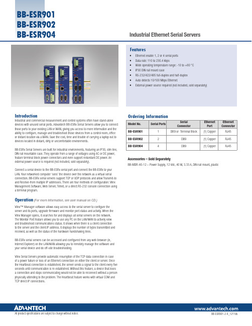
IntroductionIndustrial and commercial measurement and control systems often have stand-alone devices with unused serial ports. Advantech BB-ESRx Serial Servers allow you to connect those ports to your existing LAN or WAN, giving you access to more information and the ability to configure, manage and troubleshoot those devices from a control room, office or distant location via a WAN. Save the cost, time and trouble of carrying a laptop out to devices located in distant, dirty or uncomfortable environments.BB-ESRx Serial Servers are built for industrial environments, featuring an IP30, slim line, DIN rail mountable case. They operate from a range of voltages using AC or DC power, feature terminal block power connectors and even support redundant DC power. An external power source is required (not included, sold separately).Connect a serial device to the BB-ESRx serial port and connect the BB-ESRx to your LAN. Your networked computer ‘sees’ the device over the network as a virtual serial connection. BB-ESRx serial servers support TCP or UDP protocols and allow Transmit-to and Receive-from multiple IP addresses. There are four methods of configuration: Vlinx Management Software, Web Server, Telnet, or a direct RS-232 console connection using a terminal program.Operation(For more information, see user manual on CD.)Vlinx™ Manager software allows easy access to the serial server to configure the server and its ports, upgrade firmware and monitor port status and activity. When the Vlinx Manager opens, it searches for and displays all serial servers on the network. The Monitor Port feature allows you to use any PC on the LAN/WAN to actively view and troubleshoot communications status. It shows when there is a client connectionto the server and the client IP address. It displays the number of bytes transmitted and received, as well as the status of the hardware handshaking lines.BB-ESRx serial servers can be accessed and configured from any web browser (ie, Internet Explorer) on the LAN/WAN allowing you to remotely manage the software and your serial device and do off-site troubleshooting.Vlinx Serial Servers provide automatic resumption of the TCP data connection in caseof a power failure or loss of an Ethernet connection on either the client or server. Once the Heartbeat connection is established, the server sends a signal to the client every five seconds until communication is re-established. Without this feature, a device that loses a connection and stops communicating would not be able to reconnect without a person physically attending to the problem. The Heartbeat feature works with virtual COM and TCP direct IP connections.• Ethernet enable 1, 2 or 4 serial ports• Data rate: 110 to 230.4 kbps• Wide operating temperature range: -10 to +80 °C• IP30 DIN rail mount case• RS-232/422/485 full-duplex and half-duplex• Auto detects 10/100 Mbps Ethernet• External power source required (not included, sold separately)FeaturesAccessories – Sold SeparatelyBB-MDR-40-12 – Power Supply, 12 Vdc, 40 W, 3.33 A, DIN rail mount, plastic BB-ESR904BB-ESR901 BB-ESR902 BB-ESR904。
USB转串口使用手册
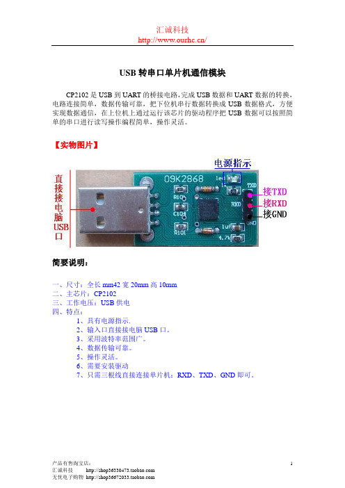
USB转串口单片机通信模块
CP2102是USB到UART的桥接电路,完成USB数据和UART数据的转换,电路连接简单,数据传输可靠,把下位机串行数据转换成USB数据格式,方便实现数据通信,在上位机上通过运行该芯片的驱动程序把USB数据可以按照简单的串口进行读写操作编程简单,操作灵活。
【实物图片】
简要说明:
一、尺寸:全长mm42宽20mm高10mm
二、主芯片:CP2102
三、工作电压:USB供电
四、特点:
1、具有电源指示.
2、输入口直接接电脑USB口。
3、采用波特率范围广。
4、数据传输可靠。
5、操作灵活。
6、需要安装驱动
7、只需三根线直接连接单片机:RXD、TXD、GND即可。
驱动安装:
1、将串口模块与计算机电脑连接,电脑提示;
2、电脑设备管理器出现下图(感叹号);
3、电脑自动弹出硬件安装向导;
4、如上图选择,然后,点击:“下一步”,提示下图,选择安装路
径;
5、点击“下一步,开始安装驱动程序;
6、提示安装完成,点击安装完成USB驱动。
7、系统再次提示安装硬件对话框,如下图操作;
8、如下图操作;
9、系统安装串行通信驱动;
10、完成安装!
串口通信测试1、查看串口号;
2、打开串口调试工具;
3、选择与设备管理器对应的串口号;
4、将串口模块的输出端TXD、RXD端接,如下图;
5、点击串口工具“手动发送”按钮;
6、如果接收区,显示内容与发送去内容相同,证明串口模块可以
正常使用!。
rs232串口用户手册usermanual
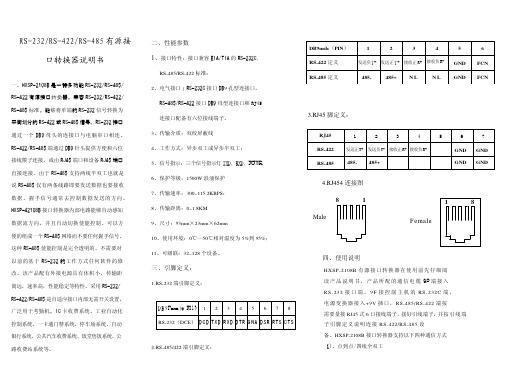
主控机 PC 机
HXSP-2108B 型转换器
485+ 485-
RS-485 通信设备
HXSP-2108B 型转换器
RS-232 通信设备
RS-485 通信设备
五、电源及防浪涌接地保护 1、外 接 电 源 HX SP - 2 1 0 8B 接 口 转 换 器 可 以 采 用 产 品 已 配 的 9V 电 源 适 配 供 电 , 也 可 以 从 其 它 直 流 电 源 或 设 备 供 电 , 供 电 电 压 力 +9V, 电 流为 100Ma。 2、浪 涌 接 地 保 护 : 普 通 的 接 口 转 换 器 没 有 配 备 大能量的保护装置,由于线路感应在接口 数据线上的瞬态高压,试图从设备的最小电 阻路径释放能量到地线。因此容易造成接口 器件的损坏。接口转换器在使用过程中为了 保证通信的安全可靠接地避免悬空。
发送负T- 发送正 T + 接收正 R+ 接收负R- GND
RS-485 定义
485-
485+ N L
N L GND
6 FCN FCN
3.RJ45 脚定义:
RJ45
1
2
3
4
5
6
RS-422
发送正T+ 发送负T- 接收正R+ 接收负R-
GND GND
RS-485 485- 485+
GND GND
4.RJ454 连接图
三、引脚定义:
1.RS-232 端引脚定义:
D B 9Female(PI N) 1 2 3 4 5 6 7 8 RS-232(DCE) D C D TXD R XD D TR G N A D SR R TS C TS
RS232串口使用说明
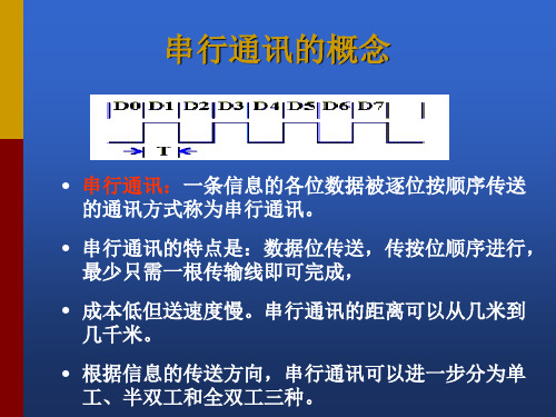
串口通讯--接口电路
能够完成上述“串<- ->并”转换功能的电路,通常称为“通用异步收 发器” (UART:Universal Asynchronous Receiver and Transmitter), 典型的芯片有:Intel 8250/8251,16550。
波特率
波特率 (bps) 110 300 1200 2400 4800 9600 1 号电缆传输距离(英尺) 5000 5000 3000 1000 1000 250 2 号电缆传输距离(英尺) 3000 3000 3000 500 250 250
RS-232C的接口信号 RTS CTS
• 请求发送(Request to send-RTS)——用来表示DTE请求 DCE发送数据,即当终端要发送数据时,使该信号有效 (ON状态),向MODEM请求发送。它用来控制 MODEM是否要进入发送状态。
• 允许发送(Clear to send-CTS)——用来表示DCE准备 好接收DTE发来的数据,是对请求发送信号RTS的响应 信号。当MODEM已准备好接收终端传来的数据,并向 前发送时,使该信号有效,通知终端开始沿发送数据 线TxD发送数据。
数据位与停止位
• 数据位:1位、2位
• 停止位:1位、1.5位、2位
流控制
.流控制在串行通讯中的作用 解决丢失数据的问题 .硬件流控制 硬件流控制常用的有RTS/CTS(请求发送/清除发送) 流控制和DTR/DSR(数据终端就绪/数据设置就绪)流 控制 .软件流控制
一般通过XON/XOFF来实现软件流控制。
• 在RTS、CTS、DSR、DTR和DCD等控制线上: • 信号有效(接通,ON状态,正电压)=+3V~+15V
关于用户手册接口USB RS232的补充信息说明书
Supplementary information relating to the users‘ manual Interfaces USB/RS232Versions 773/774IIContents 1 General 41.1 Information about the operating instructions1.2 Explanation of symbols2 Security 62.1 Security2.2 Proper use of the interfaces3 Connection 74 Setting the additional function codes 85 Programming assistant 105.1 General5.2 Installing the programming assistant5.3 Connecting the counter6 Configuring with the programming assistant 156.1 Writing and reading configuration data6.2 Configuring via USB stick6.3 Text messages7 Communication interface 197.1 Definition of the communication interface7.2 Overview of generic interface functions7.3 List of commands7.4 Syntax for read, write and function commands7.5 Command examples8 Technical data 269 Ordering information 27 Accessories 28III1 General1 General1.1 Information about the operating instructionsThese operating instructions are intended to supplement the operatinginstructions for 0773xxx and 0774xxx counters, and describe the addi-tional functions of the USB and RS232 interfaces. They contain impor-tant information for working with the multifunctional counter. Thisapplies particularly to the section on security. Compliance with all ofthe security information and procedural instructions is essential to en-sure work safety.Information about liability restrictions, copyrightprotection, warranty provisions and customerservice can be found in the operating instructions2772058.1.2 Explanation of symbolsWarningsSymbols are used to denote warnings in these operating instructions.These warnings are introduced by signal words that describe the magni-tude of the risk. Observance of these warnings is absolutely compulsory, and due caution must be exercised at all times to prevent accidents,injury and property damage.Danger!Indicates an immediate threat that will result indeath or severe injury if not avoided.41 General Warning!Indicates a possibly dangerous situation that can result in death or severe injury if not avoided. Caution!Indicates a possibly dangerous situation that can result in minor injury if not avoided.Note!Indicates a possibly dangerous situation that can result in property or environmental damage if not avoided.Tips and recommendationsHighlights useful tips and recommendation, together with information for efficient, trouble-free operation.52 Security2 Security2.1 SecurityOperating instructions 2772058 form an integral part of these operating instructions and must be observed in full. They contain safety warningsand procedural instructions for the multifunction counter. These operat-ing instructions address additional security aspects relating to the USBand RS232 interfaces.Ignoring the procedural instructions and safetyinformation in these instructions could produceextremely dangerous situations.Warning!Danger from ignoring the safety information! Anynon-compliance with the safety information, andspecifically with the warnings in this operatinginstructions, can produce dangerous situations. 2.2 Proper use of the interfacesThe interfaces can be used to configure the counter, read out oroverwrite values, and perform functions. Values can be read out at anytime. Values may only be overwritten or functions performed when themachine is stationary. If and to the extent that values have to be over-written or functions performed during the process flow, the manufac-turer of the control unit must ensure that these actions do not pose any risks for people or property.Danger!Writing values and performing function during anongoing process can produce dangerous situations.673ConnectionIf both USB connectors on the counter are occupied, the host (USB cable) takes precedence. The drive (USB stick) is automatically deactivated in suchcases.(factory setting)3 Connection4 Setting the additional function codesThese function codes apply for all basic functions, over and above the operating instructions 2772058. The factory setting is compulsory when using the USB stick and/or working with the programming assistant.Programming mode Changefunctionsettings:Save, move tonext function:Return todisplay mode:+o.Keep pressed and turnon the voltage at thesame timepress press pressAlternative display offunction codes+The function codes are displayed in text form in row 1. Press both keys simultaneously to switch to numerical display F 0 to F 35. Press again to display the number of the selection options as well. These settings are saved.4 Setting the additional function codes8Function code F24, Display, row 1Baud rate interface 01200 12400 24800 39600 419200 5*38400Parity0none1*even2oddStop bit0 1 Stop bit1* 2 Stop bits4 Setting the additional function codes95 Programming assistant5 Programming assistant5.1 Programming assistant, generalHaving decided to buy a VersaCount XP counter with interface, you now have the option of using our programming assistant to quickly program the counter. You can download the assistant free of charge from our home page at .You must install Microsoft .Net Frame Work 3.5 before you can use the pro-gramming assistant. The needed files are part of the installation file. Depending on the version, the counter can be connected to a PC and pro-grammed using a USB or RS232 cable, the USB version of the counter can also be programmed using a USB stick. The program can be used, both to transfer the programming to the counter, and to read out the counter’s current pro-gramming.The programming assistant maps all of the function codes and their values that are also set in the counter. The clear structuring of the screen allows you to save considerable time compared with conventional programming using the counter keypad.In addition, the program offers various help functions to aid you in correctly programming your counter.Apart from help texts, you will also find preset programs for standard applica-tions, which you can simply adjust to your specific application.In addition to easily programming the counter, you also have the option to archive your various program settings in electronic or hard copy format. Linking the program settings to the serial number of the counter allows you to avoid mistakenly using the wrong program settings when operating several counters.So why not visit our home page now (.) and download your free copy of the programming assistant.10115.2 Installing the programming assistantWhen you start installing the program, it will first check whether you have in-stalled .Net Framework. If not, you will see the following message: To install .Net Framework please accept the license terms. Once you have readthrough the terms carefully, please click on Accept. .Net Framework is then in-stalled automatically, you do not need to do anything else. Once theinstallation is complete, you will see the following window:Please click “Next” to start the installation.5 Programming assistant12Use the “Browse...” button to select the installation path. Once you are happy with the installation path, click “Next”.You will be asked again if you really want to install the program; confirm by clicking “Next” again to start the installation.5 Programming assistant13Installation has been successfully completed if you see this window. You can now connect your counter and start programming.5.3 Counter connectionOnce you have installed the programming assistant, you can connect the counter to the computer for installation purposes. The following window should appear about 10 seconds after connecting the counter by USB. Click“Yes, just this once” and then “Next” to start driver installation.5 Programming assistant5 Programming assistantThen click “Automatically install software (recommended)”, followed by “Next”.1415Installation is complete; you can click “Finish” and start setting your counter with the aid of the programming assistant.6Configuring with the programming assistant6.1Writing and reading configuration dataThe counter can be programmed straight from a computer using the program-ming assistant. The counter must be connected to the computer. Click the but-ton “Begin transfer” in the File/Transfer menu to transfer the configuration data to the counter. Click the button “Read” to read out the configuration data on the computer.6 Configuring with the programming assistant6 Configuring with the programming assistant 6.2 Configuring via USB stickThe USB stick can contain one global file or any number of individual configu-ration files. Any counter can be programmed with a global configuration file, whereas single files can only be used for the counter with the matching serial number. The files must be stored in the “VersaCount XP” folder on the stick.If the USB stick is inserted or if the voltage is turned on when the USB stick is inserted, the counter automatically starts configuring and looks for configura-tion files. The display first shows: USB search, followed by USB Single or USB Global. Single or Global are displayed for about 10s. If E is pressed on the key-board during this period, the new configuration file is read and saved. The dis-play then shows USB Config followed by USB done.If E is not pressed within 10s, the configuration is aborted, the previous config-uration remains active and the display shows USB abort.6.3 Text messagesDescription of the text messages generated by the USB interface on the counter.USB SEArCH Searching driveOnce a USB drive is inserted, it is checked for the existence of the “VersaCount XP“ directory and the configuration file(s) in the directory.• Global file: T_000000.CFG (irrespective of serial number)• Single file: T_003231.CFG (only for use with the counter bearing serial number 3231)USB no dir No directory foundThe interface has not found a directory called …VersaCount XP“. The configuration process has been aborted.The display returns to standard view after a couple of seconds.166 Configuring with the programming assistantUSB noFILE No file foundNeither a global nor single configuration file has been found. The configuration process has been aborted. The display re-turns to standard view after a couple of seconds.USB GLObAL Global configuration file foundA global configuration file has been found. Press “E” to con-firm and start the configuration process. Press any other key to abort the process. If no keys are pressed within 10 seconds, the process is, again, automatically aborted.USB SInGLE Single configuration file foundA single configuration file has been found. Press “E” to confirm and start the configuration process. Press any other key to abort the process. If no keys are pressed within 10 seconds, the process is, again, automatically aborted.USB COnFIG Counter is being configuredThe counter is configured using the file it has found.USB no CFG No configuration command executedA configuration file has been found and the configuration started, but no command has been executed. Very probably, the file does not contain any configuration commands (com-ments not excluded).USB donE Configuration completeThe configuration was completed without error. In order to re-configure the counter, remove the USB drive and insert again.USB E1Error 1: Drive was removed before configuration started A configuration file was found, but the interface could no lon-ger detect a drive when the configuration process was started manually. The process is aborted and a restart prevented since no configuration has taken place. The display returns to stan-dard view after a couple of seconds.176 Configuring with the programming assistantrESEt E2Error 2: Drive was removed during the configuration pro-cessThe USB drive was removed during configuration. The process is aborted. The counter must be restarted to reset any possible errors in the configuration. This is shown by the message “rE-SEt” on the display. Press any key on the counter to restart it. In order to reconfigure the counter, remove the USB drive and insert again.rESEt E3 XXX Error 3: A configuration command has produced an error messageA command error has occurred during configuration of the counter, i.e., one of the commands in the configuration file re-ported an error. The digits shown here as XXX (e.g., 014) refer to the command error in the configuration file. It represents the sequential number of the executed commands, not the row number. Example: If error “14” is displayed, the error is con-tained in the 14th command in the configuration file, irrespec-tive of how many comments are noted.USB Abort Configuration has been abortedThis message appears in the display if the configuration pro-cess is not started within the specified time after finding the configuration file, or if the process is manually aborted. The display returns to standard view after a couple of seconds.187 Communication interface 7 Communication interface7.1 Definition of the communication interfaceGeneric Interface for VersaCount 77xGeneral:Explanation of the term “Generic Interface”The generic interface provides basic functions for reading/writing counter values and function settings to/from the counter. An ASCII protocol is used for communication, but other, higher protocols can be set. This documentation describes the functionality of the generic interface between the counter and the interface PCB.Following is only an overview of the generic interface. For detailed view, please visit our webpage .Hardware protocol:The generic interface is based on RS232.Baud rate: 38.4 kBdBits: 8Parity: evenStop bits: 1Software protocol:The generic interface between VersaCount 77x and the interface PCB is based on ASCII commands and data values in ASCII format.The internal counter structure of the values is binary and optimized for high counting speeds. The values exchanged via the generic interface are ASCII values. The counter converts the values into its internal format.197 Communication interface7.2 Overview of generic interface functions:Basic functions:1. Read / write the basic counter functions2. Read / write the function codes3. Read / write the USER monolayer timesRead / write values:1. Read / write the preset values2. Read / write the prescaler value3. Read / write the counter values4. Read the tachometer valueSpecial functions:1. Reset the counting values2. Reset the counter3. Activate/deactivate status reports (changes in preset status)4. Read the software version5. Read the software number6. Save all values to the EEPROM7. Direct access to the display, e.g., for messages7.3 List of commands:Command R / W / F Value DescriptionBFN R/W0..4Set the basic function F00W0 / 1Set the default values F01R / W See Manual Function code 1 ( F01 ) ::R / W::::F35R / W::Function code 35 ( F35 ) UT1R / W 000.01 to 599.99Output user monolayertime 1207 Communication interface UT2R / W 000.01 to 599.99Output user monolayertime 2UT3R / W 000.01 to 599.99Output user monolayertime 3PR0R / W-999999 .. .999999Value for preselect 0PR1R / W-999999 .. .999999Value for preselect 1PR2R / W-999999 .. .999999Value for preselect 2PSC R / W000001 .. 999999Prescaler valueCNT R / W-999999 .. 999999Counting valueTAV R-999999 .. 999999Tachometer valueTOT R / W000000 .. 999999TotalizerBAT R / W000000 .. 999999Batch counterSU1R / W000000 .. 999999Sub-total 1SU2R / W000000 .. 999999Sub-total 2SWR R YYYY Software versionSWP R XXXXXX Software numberSNR R XXXXXX Counter serial number OST R XYZ Starting status X,Y,Z =P0,P1,P2RST F Reset counter deviceRSC F Reset counting values MON F Output monitoring ON MOF F Output monitoring OFF STV F Save values to EEPROM NOP F No functionPNG F Ping ->response =“VersaCount 772”217 Communication interfaceCSE F Checksum enableCSD F Checksum disableBLI R / W0 .. 15Brightness setting fordisplay illumination REM W0 .. 99Function for display access WFK W0 .. 99Wait for key to be pressedby operatorD00W0 .. 255Delete display when ac-cessing displayD01-D15W0 .. 255Write sample to displayR = ReadW = WriteF = Function227 Communication interface 7.4 Syntax for read, write and function commands Syntax for read commands:The commands are comprised of the command name (3 characters) followed by a space and the code for read (“R”). The command ends with CR (0Dh). (0Dh)C MD R CRThe counter responds by repeating the command name and indicates the return value, separated by a space. The response ends with CRC M D-123456CR Unknown (incorrect) commands generate the following response:E R R CRSyntax for write commands:The commands are comprised of the command name (3 characters) followed by a space and the code for write (“W”) and the value to be written, which con-sists of up to 6 digits and the algebraic sign. The command ends with CR (0Dh).C MD W-123456CRThe counter responds by repeating the name of the command, followed by “OK” if the command has been executed or “ER” if the command could not be executed, e.g., because of an invalid value. The response ends with CR. Command has been executed:C MD O K CR237 Communication interfaceCommand error:C MDE R CRSyntax for function commands:Function commands are commands for calling up functions within the counter, without reading or writing values.C MD CRResponse:Command has been executed:C MD O K CRCommand error:C MDE R CR7.5 Sequence for setting and alteringSequence for setting valuesSome values / settings can be transferred whenever you like, others require adherence to a specific sequence.1. If the basic function of the counter is altered, the default values assignedto the basic function are automatically loaded. As such, function codes must always be changed after altering the basic function. Otherwise the counter will overwrite the changes made to the function codes.2. All counting values are automatically deleted if the prescaler is altered. So changes to the prescaler must always be made before altering the counting values.247 Communication interface 3. Initially, all values are altered only in the working memory. Once the values have been transferred, they must be saved to the EEPROM using the STV com-mand. Changes to function codes do not become effective until the counter has been restarted/reset (“RST”).The following sequence should be adhered to when changing values:- Set basic function (BFN)- Set default values (F00)- Set function codes (F01 (35)- Save values to EEPROM (STV)- Reset/restart counter to activate the changes (RST)- Set the prescaler (PSC)- Set the preselect values (PR0 .. PR2)- Set the counting values (CNT, TOT, SU1, SU2)- Save all values to EEPROM (STV)Any function not mentioned here does not have to adhere to a specific sequence. All read functions can be used at any time.258 Technical data8 Technical dataThese operating instructions only contain the supplementary technical data for the interfaces. Further technical data can be found in the operating instruc-tions 0772058.RS-232 interface (VersaCount 774)Also known as EIA-232, it is one of the stan-dards for serial interfaces.Socket on the counter:Micro Fit 3.0 from Molex, 3-pinData cable:Micro Fit 3.0 socket to 9-pin D-Sub connector(S/UTP CAT-5 cable)Cable length:max.15 mBaud rate:38.400 baud / Parity: even / 8 bit / Stop bits: 1(factory setting, see section 4 for settingoptions)USB interface (VersaCount 773)The Universal Serial Bus (USB 2.0) is a serial bus system for connecting external appliances during operation.Socket on the counter: for USB stick: Type Afor USB stick: Type Mini ABData cable: A connector to B-Mini connector, 5-pin Cable length: max. 3 mUse USB cables with noise filters to suppressinterference.For a failure-free operation we recommendour USB-cable No. 3 539 835269 Ordering information 9 Ordering informationUSB USB Display Relay12 - 30 VDC100 - 240 VAC LCD reflective1VC773-101VC773-141 LCD reflective2VC773-102VC773-142 LCD transflective positive1VC773-201VC773-241 LCD transflective positive2VC773-202VC773-242 LCD transmissive white1VC773-301VC773-341 LCD transmissive white2VC773-302VC773-342 LCD transmissive red1VC773-401VC773-441 LCD transmissive red2VC733-402VC773-442 LCD transmissive green1VC773-501VC733-541 LCD transmissive green2VC773-502VC773-542RS232RS232 Display Relay12 -30 VDC100 - 240 VAC LCD reflective1VC774-101VC774-141 LCD reflective2VC774-102VC774-142 LCD transflective positive1VC774-201VC774-241 LCD transflective positive2VC774-202VC774-242 LCD transmissive white1VC774-301VC774-341 LCD transmissive white2VC774-302VC774-342 LCD transmissive red1VC774-401VC774-441 LCD transmissive red2VC774-402VC774-442 LCD transmissive green1VC774-501VC774-541 LCD transmissive green2VC774-502VC774-542 Reflective: Black digits, light reflection backgroundTransflective positive: Black digits, illuminated backgroundTransmissive white: White lit digits, black backgroundTransmissive red: Red lit digits, black backgroundTransmissive green: Green lit digits, black background2710 Accessories10 AccessoriesAccessoriesUSB cable, ASS 3953 CA / 1.5 m G3539835G3539839 "USB stick 2.0 - 2GB (includes the soft-ware for the programming assistant)"Cable RS232 3m G1774001 Cable RS232 5m G1774002 Cable RS232 10m G1774003 Cable RS232 15m G177400428293031Version: 1 200713 HF1Danaher Sensors and Controls Specialty Products 2100 West Broad Street | Elizabethtown NC, 28337 1-800-390-6405 | 。
新代系统RS232传输软件接线及使用说明
新代系统RS232传输软件接线及使用说明1、硬件要求1.1、本系统使用前需要一台支持RS232协议的计算机;1.2、需要一个RS232串行接口线;1.3、需要连接一个RS232转USB适配器(如果计算机没有RS232接口)。
2、接线步骤2.1、将RS232转USB适配器连接至计算机;2.2、将RS232串行接口线的一端连接至RS232转USB适配器;2.3、将RS232串行接口线的另一端连接至目标设备的RS232串行接口。
3、软件安装及配置3.1、最新版本的新代系统RS232传输软件并进行安装;3.2、打开软件并选择菜单中的“设置”选项;3.3、在设置界面中选择适配器端口,确保选择的端口与步骤2中接线的端口一致;3.4、配置通信波特率、数据位、校验位和停止位,确保与目标设备的要求一致;3.5、保存并关闭设置界面。
4、软件使用4.1、打开新代系统RS232传输软件;4.2、在软件的主界面中,选择要进行的传输操作(如、删除等);4.3、根据软件界面的提示,按照需求输入相应的文件路径或指令;4.4、开始传输按钮开始传输过程;4.5、传输完成后,根据软件界面的提示,进行相应的操作(如重启目标设备等)。
5、附件本文档涉及的附件请参考附件列表。
6、法律名词及注释6.1、RS232协议:RS232是一种串行通信协议,用于计算机与外部设备之间的数据传输;6.2、波特率:波特率指每秒钟传输的波特数,是衡量数据传输速率的单位;6.3、数据位:数据位指每个数据字节中包含的数据位数;6.4、校验位:校验位用于检测数据传输中的错误,并进行纠正;6.5、停止位:停止位用于指示数据传输的开始和结束。
电脑USB转TTL串口RS232串口模块

电脑USB转TTL串口/RS232串口模块对于一些学校、工业、科研客户来说,电脑的串口非常重要,很多设备都必须采用串口和电脑端软件连接,很多电路模块可以非常直观方便地利用串口调试软件进行调试,很多仪器必须通过串口进行通讯和数据交换。
但是目前笔记本电脑因为空间的限制和其他方面考虑的原因都没有串口,甚至一些台式电脑也取消了串口配置,这让我们迫切需要串口的客户非常苦恼。
USB转串口模块全称为USB to Serial port Module,它可以将USB接口虚拟成一个串口,解决客户无串口的苦恼。
现在市面上的USB转串品的设备可谓是琳琅满目,质量也是参差不齐。
造成这种现象的根本原因就在于控制芯片的不同。
现在USB转串口桥接芯片有很多,比如CP2102、FT232、PL2303等等。
但并非每一种芯片都可以用作ISP下载。
经过测试CP2102是不能下载的,而FT232可以下载,但其价格实在不菲。
最为适中的就是台湾生产的PL2303,可以稳定下载,并可以支持多种操作系统。
PL2303HX采用28脚贴片SOIC封装,工作频率为12MHZ,符合USB 1.1通信协议,可以直接将USB信号转换成串口信号,波特率从75~1228800,有22种波特率可以选择,并支持5、6、7、8、16共5种数据比特位,是一款相当不错的USB转串口芯片。
产品1:采用PL2303芯片的USB转TTL串口模块每个12元含一根4芯杜邦连接线这是我们用PL2303芯片开发的USB转串口模块,采用机器自动焊接都经人工检测,电路板只有30*16*7毫米,模块一共引出5根脚,引脚电平为TTL,引脚定义如下:+5V、P3.0 TXD 、P3.1 RXD 、GND 地线、+3.3V 。
其中+5V和+3.3V电源输出线一般情况下都不用的,不需要连接。
现在购买PL2303模块我们还赠送一根30厘米长的杜邦连接线,它一头是四位一体的插座可以直接插到我们的2303模块上,另一头是四个独立的杜邦头,可以灵活插到设备上,非常方便。
USB-RS232驱动程序安装说明
USB-RS232驱动程序安装说明来源: 作者:概述USB-RS232电缆是通过将电脑的USB口模拟成传统的串行口系统要求请在使用USB编程电缆之前确认你的电脑是IBM PC兼容型并具备以下最低系统要求:● Intel兼容586DX4-100MHz中央处理器或更高● 一个标准的USB接口(4-pin A型插座)驱动程序的安装驱动程序的安装非常简单,只需按提示进行即可,以Windows XP为例,按以下步骤进行:1、 打开电脑主机,插入驱动程序光盘。
2、 将USB-RS232电缆插入电脑的USB接口,Windows将检测到设备并运行添加新硬件向导帮助你设置新设备,并单击下一步继续。
如果Windows没有提示找到新硬件,那么在设备管理器的硬件列表中,展开“通用串行总线控制器”,选择带问号的USB设备,单击鼠标右键并运行更新驱动程序。
3、 Windows将检测到安装信息,并出现如下没有通过Windows徽标测试的信息框,单击“仍然继续”。
4、 继续安装,让Windows拷贝驱动程序文件到你的硬盘。
5、 当Windows显示完成找到新硬件向导,单击“完成”结束安装。
6、 安装完成后,请确认在Windows的“开始设置控制面板系统硬件设备管理器”菜单的“端口(COM和LPT)”展开条目中出现“Prolific USB- to-Serial Bridge (COMx)”,这个COMx就是USB编程电缆使用的COM口号,该端口号与电脑有关,一般为COM3或COM4,以后每次使用只要插入编程电缆就会出现该COM口,你只需在编程软件或通信软件等应用软件中选中该COM口号即可通信。
驱动程序的删除删除驱动程序是为了释放COM口资源以便其他设备使用,或驱动程序故障时需将其删除后重新安装,按下面步骤删除驱动程序:1、 从你的电脑上拔下USB编程电缆。
2、 运行面板中的添加或删除程序”,选择“Prolific USB- to-Serial Bridge (COMx)”,单击删除按钮。
RS232到USB无线转接器说明书
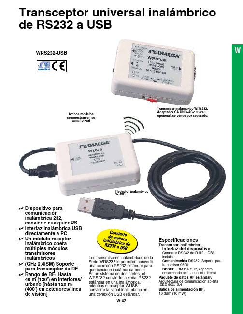
Transceptor universal inalámbrico de RS232 a USBU D ispositivo paracomunicación inalámbrica 232, convierte cualquier RSU I nterfaz inalámbrica USB directamente a PC U U n módulo receptor inalámbrico opera múltiples módulos transmisores inalámbricos U (GHz 2,4ISM) Soporte para transceptor de RF U R ango de RF: Hasta 40 m (130') en interiores/urbano [hasta 120 m (400') en exteriores/línea de visión]Los transmisores inalámbricos de la Serie WRS232 le permiten convertir una conexión RS232 estándar para que funcione inalámbricamente. Es un sistema de dos partes, el WRS232 convierte la señal RS232 estándar en una inalámbrica, mientras el receptor WUSB convierte la señal inalámbrica en una conexión USB estándar.Especificaciones Transmisor inalámbrico I nterfaz del dispositivo : Conector RS232 de RJ12 a DB9 incluido Comunicación RS232: Soporte para transmisor 9600 BPSRF:ISM 2,4 GHz, espectroensanchado por secuencia directa Paquete de datos RF estándar: Arquitectura de comunicación abierta IEEE 802.15.4Salida de alimentación RF:10 dBm (10 mW)Transmisor inalámbrico WRS232. Adaptador CA UNIV-AC-100/240opcional, se vende por separado.Receptor inalámbrico WUSB.Ambos modelos se muestran en su tamaño realC o nv i e r t ed e m a n er ai n al ám b r i c ad e R S 232 a U S B W WRS232-USBUsando el transceptor inalámbrico RS232 a USBNota: Debido a las normas de frecuencia de transmisión, este producto únicamente puede ser utilizado en Estados Unidos, Canadá y Europa Completo de serie con software y manual del operador.Ejemplo de pedido: Módulos transmisores y receptores inalámbricos WRS232-USB , cable RS232 con conector RJ12 a DB9,conector macho/macho DB9 y cable USB.Opción de comunicación inalámbrica RS232 para regulador de temperatura iSeries.Voltaje de suministro: Directamente del instrumento central, mediante conexión RJ12 o adaptador CA opcionalCorriente de suministro: 60 mAAdaptador CA: 100 a 240 Vca, 50 a 60 HzTensión de salida: 9 Vcc @ 1,7 AClavija de salida (hembra): Centro positivo, coax. 2,0/5,5/10 mmReceptor inalámbricoInterfaz de PC: Compatible con USB 1.1 y USB 2.0Tipo de cable: USB 4P(A) macho a mini 5P(B) macho 1,8 m (6') de largo incluidoRango de RF: Hasta 40 m (130'): E n interiores/urbano H asta 120 m (400'): E n exteriores/línea de visión Condiciones de entorno operativo: 0 a 50 °C, 0 a 90% de HR (sin condensado)Dimensiones: 70 de largo x 51 de ancho x 20 mm de altura (2,75 x 2 x 0,80")Termómetro infrarrojo manual Serie OS533 con opción inalámbrica RS232.Transmisor inalámbrico PATENTEPATENTADORegistrador de gráfico circular Serie CTXLReceptor Transmisor inalámbricoTM。
RS232端口测试仪操作手册
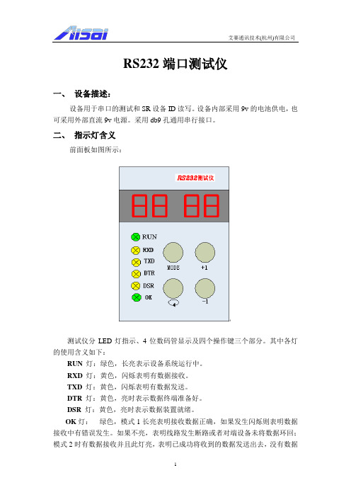
RS232端口测试仪一、设备描述:设备用于串口的测试和SR设备ID读写。
设备内部采用9v的电池供电,也可采用外部直流9v电源。
采用db9孔通用串行接口。
二、指示灯含义前面板如图所示:测试仪分LED灯指示、4位数码管显示及四个操作键三个部分。
其中各灯的使用含义如下:RUN 灯:绿色,长亮表示设备系统运行中。
RXD灯:黄色,闪烁表明有数据接收。
TXD灯:黄色,闪烁表明有数据发送。
DTR 灯:黄色,亮时表示数据终端准备好。
DSR 灯:黄色,亮时表示数据装置就绪。
OK灯:绿色,模式1长亮表明接收数据正确,如果发生闪烁则表明数据接收中有错误发生。
如果不亮,表明线路发生断路或者对端设备未将数据环回;模式2时有数据接收并且此灯亮,表明已成功将收到的数据发送出去,没有数据接收时此灯为暗;模式3~11时长亮表明在此速率下与对端设备通信正常,此时右侧数码管显示数值为被测设备工作速率。
四个数码管显示分如下两种:(1)模式1~11(b)时只显示三个数码管,最左侧数码管显示为模式值,表示端口测试仪的当前工作模式,显示值用16进制表示,范围从1到b(”1~9”表示模式1至9,字母”A”表明模式10,字母“b”表示模式11);右侧两个数码管显示串口工作速率信息,模式一和二波特率固定值为9.6,即工作速率为9600bps。
3~11模式下默认值为9.6,此时,让本测试仪自动循环或按+1或-1键都可以改变其波特率值,如果未与对端设备建立有效通讯,则OK灯不亮,同时一定时间间隔后速率将变为19200(显示19),如果仍未建立有效通讯则间隔一定时间后再变为1200(显示1.2),如此自动循环,右边数码管显示值依次为…9.6—19—1.2—2.4—4.8—9.6…;自动变化的同时可以按+1键对其进行操作,如显示9.6时按+1键则显示变为19,即速率从9600变为了19200bps,再按一次为1.2,如此下去依次显示9.6—19—1.2—2.4—4.8—9.6…;同理按-1键则可依次显示9.6—4.8—2.4—1.2—19—9.6…,其中1.2代表1200bps,2.4代表2400bps,4.8代表4800bps,9.6代表9600bps,19代表19200 bps。
RS232串口使用说明.
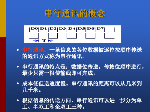
RTS
CTS DELL
4
5 22
请求发送
清除发送 振铃指示
RTS
CTS DELL
2、RS-232C的接口信号 DSR DTR
• RS-232C规标准接口有25条线,4条数据线、11条控制 线、3条定时线、7条备用和未定义线,常用的只有9根, 它们是: • (1)联络控制信号线: • 数据装置准备好(Data set ready-DSR)——有效时 (ON)状态,表明通信装置处于可以使用的状态。 • 数据终端准备好(Data set ready-DTR)——有效时(ON) 状态,表明数据终端可以使用。 • 这两个信号有时连到电源上,一上电就立即有效。这 两个设备状态信号有效,只表示设备本身可用,并不 说明通信链路可以开始进行通信了,能否开始进行通 信要由下面的控制信号决定。
数据位与停止位
• 数据位:1位、2位
• 停止位:1位、1.5位、2位
流控制
.流控制在串行通讯中的作用 解决丢失数据的问题 .硬件流控制 硬件流控制常用的有RTS/CTS(请求发送/清除发送) 流控制和DTR/DSR(数据终端就绪/数据设置就绪)流 控制 .软件流控制
一般通过XON/XOFF来实现软件流控制。
• (2)数据发送与接收线:
RS-232C的接口信号 ---TxD RxD
• 发送数据(Transmitted data-TxD)——通过TxD终端将串 行数据发送到MODEM,(DTE→DCE)。
• 接收数据(Received data-RxD)——通过RxD线终端接收 从MODEM发来的串行数据,(DCE→DTE)。
• 在RTS、CTS、DSR、DTR和DCD等控制线上: • 信号有效(接通,ON状态,正电压)=+3V~+15V
RS232 接口的U盘读写器 使用说明
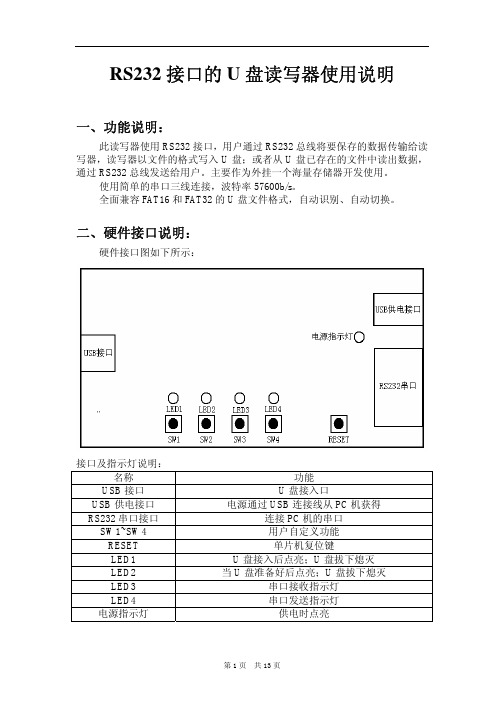
一、功能说明:
此读写器使用 RS232 接口,用户通过 RS232 总线将要保存的数据传输给读 写器,读写器以文件的格式写入 U 盘;或者从 U 盘已存在的文件中读出数据, 通过 RS232 总线发送给用户。主要作为外挂一个海量存储器开发使用。 使用简单的串口三线连接,波特率 57600b/s。 全面兼容 FAT16 和 FAT32 的 U 盘文件格式,自动识别、自动切换。
1 结果
2~5 0
(8)获得磁盘剩余空间:
命令格式: 命令字节 内容 1 0x07 2~37 无意义
命令说明: 获得磁盘的剩余空间。 命令应答: 应答字节 内容
1 结果
2~5 返回的数据长度(4)
4 个字节 磁盘的剩余空间(以字节为单位)
(9)检测 U 盘是否准备好:
命令格式: 命令字节 内容 1 0x08 2~37 无意义
(12)返回上一级目录:
命令格式: 命令字节 内容 1 0x0b 2~37 无意义
命令说明: 返回到当前目录的上一级目录中。 命令应答: 应答字节 1 2~5 内容 结果 0 注:正确返回上一级目录后,以后的操作都是在该目录下进行的,除非使用命令 跳转到其他子目录或根目录。
(12)返回到根目录:
命令格式: 命令字节 内容 1 0x0c 2~37 无意义
第5页 共 13 页
注意:在写入过程中 U 盘指示灯会快速闪烁,此时不可拔下 U 盘,否 则会丢失数据甚至损坏文件。
(7)删除文件或目录:
命令格式: 命令字节 内容 1 0x06 2~5 无意义 6~16 11 个字节的文件名或目录名 17~37 无意义
命令说明: 删除文件或目录。 注:在删除目录前请先删除该目录下的文件和子目录,包括其子目录中的 文件和目录。 命令应答: 应答字节 内容
RS232串口使用说明

RS-232C的接口信号 RTS CTS
• 请求发送(Request to send-RTS)——用来表示DTE请求 DCE发送数据,即当终端要发送数据时,使该信号有效 (ON状态),向MODEM请求发送。它用来控制 MODEM是否要进入发送状态。
• 允许发送(Clear to send-CTS)——用来表示DCE准备 好接收DTE发来的数据,是对请求发送信号RTS的响应 信号。当MODEM已准备好接收终端传来的数据,并向 前发送时,使该信号有效,通知终端开始沿发送数据 线TxD发送数据。
并行接口
• 目前,计算机中的并行接口主要作为打印机端口,接口使用的不再是36 针接头而是25针D形接头。所谓“并行”,是指8位数据同时通过并行线 进行传送,这样数据传送速度大大提高,但并行传送的线路长度受到限 制,因为长度增加,干扰就会增加,容易出错。 • 现在有五种常见的并口:4位、8位、半8位、EPP和ECP,大多数PC机配 有4位或8位的并口,许多利用Intel386芯片组的便携机配有EPP口,支持 全部IEEE1284并口规格的计算机配有ECP并口。
星辰科技 USB 到 RS232 RS422 RS485 串行适配器产品说明说明书
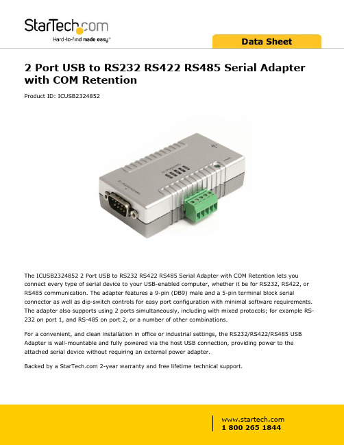
2 Port USB to RS232 RS422 RS485 Serial Adapter with COM RetentionProduct ID: ICUSB2324852The ICUSB2324852 2 Port USB to RS232 RS422 RS485 Serial Adapter with COM Retention lets you connect every type of serial device to your USB-enabled computer, whether it be for RS232, RS422, or RS485 communication. The adapter features a 9-pin (DB9) male and a 5-pin terminal block serial connector as well as dip-switch controls for easy port configuration with minimal software requirements. The adapter also supports using 2 ports simultaneously, including with mixed protocols; for example RS-232 on port 1, and RS-485 on port 2, or a number of other combinations.For a convenient, and clean installation in office or industrial settings, the RS232/RS422/RS485 USB Adapter is wall-mountable and fully powered via the host USB connection, providing power to the attached serial device without requiring an external power adapter.Backed by a 2-year warranty and free lifetime technical support.Certifications, Reports and Compatibility Applications•Adapting and expanding POS systems•Great for Industrial programmers looking to test new code with serial devices•Connect serial RS232, RS422, or RS485 devices to notebooks ortablet PC’s through the USB port•Perfect for controlling, monitoring, and diagnosing manufacturing machines (CNC, Process Control Equipment, Bar Code Scanners,Serial Printers)•Security device control (key panels, cameras, card readers)Features•Backwards compatible with USB 1.1•USB-powered; No additional external power adapter required •Both ports can function simultaneously with mixed or matchedcommunication protocols•Includes a bracket for wall mounting the USB to Serial adapter •Features rugged screw-lock USB port to ensure cords are not accidentally disconnected•Ability to rename devices for easy recognition•COM Port assignments maintained after reboot•Port 1 (DB9) configurable for RS232, RS422, or RS485; Port 2 (Terminal Block) configurable for RS422 or RS485•Multiple interface modes, including: 4 wire RS422(TxD+/-, RxD+/-), and 2 wire RS485 (DATA+, DATA-)•Supports RS-485 Auto Transceiver Turn Around by Unique Featured ATTA Hardware•External power adapter can be used (not required) if your device needs extra power beyond what the USB host can provide •Transmission Echo for RS485 collision detection•USB to 2 Port Straight-Through RS232/422/485 Serial AdapterWarranty 2 YearsHardware Bus Type USB 2.0Chipset ID FTDI - FT2232HInterface SerialPort Style External HubPorts2Performance Data Bits7, 8FIFO128 BytesFlow Control Xon/Xoff, Hardware, and NoneMax Baud Rate921.6 KbpsParity Odd, Even, Mark, Space, and NoneSerial Protocol RS-232/422/485Stop Bits1, 2Connector(s)Connector Type(s) 1 - USB Type-A (4 pin) USB 2.0 MaleExternal Ports 1 - DB-9 (9 pin, D-Sub) Male1 - Terminal Block (5 Wire)Software OS Compatibility Windows® CE (4.2, 5.0, 6.0), XP Embedded, 98SE, 2000,XP, Vista, 7, 8, 8.1, 10Windows Server® 2003, 2008 R2, 2012, 2012 R2, 2016,2019Mac OS X® 10.6 to 10.15Linux 2.4.x to 4.4.x LTS Versions onlyIndicators LED Indicators 1 - Red - Power LEDPower Center Tip Polarity PositiveOutput Current0.385AOutput Voltage 5 DCPlug Type BPower Source Not Included (not required for standard applications) Environmental Humidity5~95% RHOperating Temperature0°C to 55°C (32°F to 131°F)Storage Temperature-20°C to 85°C (-4°F to 185°F)PhysicalColor GrayCharacteristicsEnclosure Type PlasticProduct Height0.9 in [2.3 cm]Product Length 3.2 in [82.3 mm]Product Width 1.7 in [44.2 mm]Weight of Product10.6 oz [300 g]PackagingPackage Height 1.6 in [40 mm]InformationPackage Length8.2 in [20.8 cm]Package Width 5.7 in [14.4 cm]Shipping (Package) Weight10.9 oz [310 g]What's in the Box Included in Package 1 - Wall mounting bracket1 - USB to RS232/RS422/485 Adapter1 - USB A to B Cable1 - Driver CD1 - Installation GuideProduct appearance and specifications are subject to change without notice.。
- 1、下载文档前请自行甄别文档内容的完整性,平台不提供额外的编辑、内容补充、找答案等附加服务。
- 2、"仅部分预览"的文档,不可在线预览部分如存在完整性等问题,可反馈申请退款(可完整预览的文档不适用该条件!)。
- 3、如文档侵犯您的权益,请联系客服反馈,我们会尽快为您处理(人工客服工作时间:9:00-18:30)。
USB转串口(RS232)线用户手册V1.4
感谢你购买USB转串口线,这种独特的连接产品
能够使你通过USB口连接更多的标准串口(RS232)设备
同时可获得更高的传输速率(最高的达1.2Mbps)
适用对象:
Modem、ISDN-TA、数码相机、条码扫描器、Palm、掌
上电脑PDA(WinCE系统)、标签打印机、POS系统、工业
控制机、安全门禁系统等。
甚至可组成多个Modem池。
包装清单
此USB转串口线产品包装内包含以下物品
●USB转串口线
●驱动程序软件安装盘
●本用户手册
概述
此USB转串口线可使你在串口(RS232)和USB口之间非常容易地建立建立可靠的连接。
通过利用USB接口具有的即插即用和热插拔的能力可以给串口(RS232) 外围设备提供非常容易使用的环境。
它的设计可以让你方便地连接诸如手提电话、数码相机、ISDN-TA、Modem等设备,并提供高达230Kbps的传输速率。
(某些特殊情况下甚至可达到1Mbps以上的速率)。
此USB转串口线和驱动程序无需对软硬件系统做任何改动就可以模拟一个串行口(通常为COM3),传统的串行口(RS232)外围设备无需做任何改动即可通过USB口使用。
功能
此USB转串口线提供如下功能:
●单片(ASIC) USB端口到串行端口通信
●支持Windows98/Me和Windows2000
●完全兼容USB v1.1和USB CDC V1.1规范
●USB全速连接
●USB总线直接取电,无需外接电源
●支持自动握手协议
●高达1 Mbps以上的传输速率
●支持RS232标准串行端口
●支持远程唤醒和电源管理
系统要求
请在使用此USB转串口线线前,请确定你的电脑是IBM PC兼容型并具备以下最低的系统要求:
●Intel兼容486DX4-100 MHz中央处理器或更高
●一个标准的USB接口(4-pin)并有此符号
●运行的操作系统为Windows 98/Me 或 Windows 2000
驱动程序安装
请按照下面的步骤安装USB转串口线线驱动程序:
1. 打开将要连接USB转串口线的电脑的电源,并确定将要连接的USB口已经启动并正常工
作。
2.将USB转串口线插入USB接口,Windows将检测到设备,并运行添加新硬件向导帮助你设置新
设备,单击下一步继续。
3.插入USB转串口线驱动程序盘,并单击下一步继续。
选择为硬件搜索最新的驱动程序然后单
击下一步,选择从软盘安装然后单击OK。
4.Windows将检测到安装信息(Serwpl.inf)并显示
USB-to Serial设备, 单击下一步继续安装。
5.单击下一步继续,让Windows拷贝必要的文件到你的硬盘。
6.当Windows显示安装了新设备USB-to Serial Cable所必需的软件,单击完成。
设置串口设备(以Modem为例)
请按照下面的步骤来连接Modem到PC的USB接口:
1. 关闭Modem电源,将USB转串口线的串口连接头插入到你的Modem。
如果Modem上已经插有
普通串口线,请请将它连接到USB转串口线来取代它。
然后打开打印机电源。
2.打开你的电脑并将USB转串口线的USB连接头插入USB接口。
3.然后按照正常的安装方法,单击开始,设置,添加新硬件。
4.在安装过程中根据提示设置Modem端口到COM3:(USB to Serial Port Cable).
5.当提示你成功安装以后,请运行调制解调器,诊断,看看是否正常。
驱动程序删除
按照下面的步骤从Windows系统里删除USB转串口线驱动程序:
1.从你的电脑上拔下USB转串口线。
2.运行USB转串口线驱动盘里的DRemover98_2K.exe程序,并按照提示进行。
3.重新启动计算机。
拒绝条款
此文件以提供信息为目的,里面条目和内容在修改时并不另行通知。
因为此说明文件中的内容或变更所引起的直接或间接或与此相关的任何损失和错误,厂商均不负责任。
此文件的任何部分在未经厂商允许的情况下,均不允许以任何电子或书面的方式散播(包括复印、记录、电子拷贝等)。
所有商标名称和产品名称是它们各自生产厂商的商标或注册商标。
FCC 声明
This device generates and uses radio frequency and may cause interference to radio and television reception if not installed and used properly. This has been tested and found to comply with the limits of a Class B computing device in accordance with the specifications in Part 15 of FCC Rules. These specifications are designed to provide reasonable protection against such interference in a residential installation. However, there is no guarantee that interference will not occur in a particular installation.
If this device does cause harmful interference to radio or television reception, which can be determined by plugging the device in and out, the user can try to correct the interference by one or more of the following measures:
●Reorient or relocate the receiving antenna.
●Increase the separation between the device and receiver.
●Connect the computer into an outlet on a circuit different from that to which the receiver is
connected.
●Consult the dealer or an experienced radio/TV technician for help.
Copyright ©2001 All rights reserved.。
