ANSYS轴承单元
轴承支架的ANSYS分析
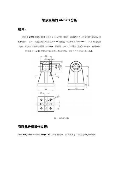
轴承支架的ANSYS分析题目:试应用ANSYS有限元软件分析图1所示支座(铸造)内部的应力、应变和变形分布,并校核强度。
已知,底板上有四个直径为14mm的圆孔(距离端面均为30mm),其圆面受到全约束,已知材料的弹性模量E=210Gpa,泊松比μ=0.3,许用应力[σ]=160MPa,右端φ60的孔端面(A-B)受到水平向左的分布力作用,分布力的合力大小为15kN。
图1 零件尺寸图有限元分析操作过程:GUI:Utility Menu→File→Change Title,弹出新菜单,如下图所示,命名为file_dazuoyeGUI :MainMenu→Preprocessor→Modeling→Creat→Keypoints→In Active CS,打开创建关键点对话框。
在【Keypoint number】文本框中输入1,在【Location in active CS】文本框中分别输入0,0,0,单击apply按钮。
同理建立另外三个关键点,编号为2至4,分别为(140,0,0)、(140,140,0)、(0,140,0)GUI:MainMenu→Preprocessor→Modeling→Creat→Areas→Arbitrary→Through Kps,弹出拾取线对话框,依次拾取刚刚建立的4条个关键点,需要安顺时针或者逆时针顺序。
点击OK 按钮。
GUI:MainMenu→Preprocessor→Modeling→Creat→Areas→Circle→Solid Circle,弹出拾取线对话框,按照下图所示进行设置输入。
点击OK。
同理在底部建立另外三个孔,半径均为7mm,输入坐标分别为(110,30)、(30,110),(110,110),最终建立图形如下所示。
GUI:MainMenu→Preprocessor→Modeling→Operate→Booleans→Divide→Area By Area,弹出拾取面对话框,先拾取大面,点击OK,再次弹出拾取面对话框,再拾取四个小面,点击OK,进行面切割,切割完图形如下所示。
基于ANSYS的空气静压轴承有限元分析
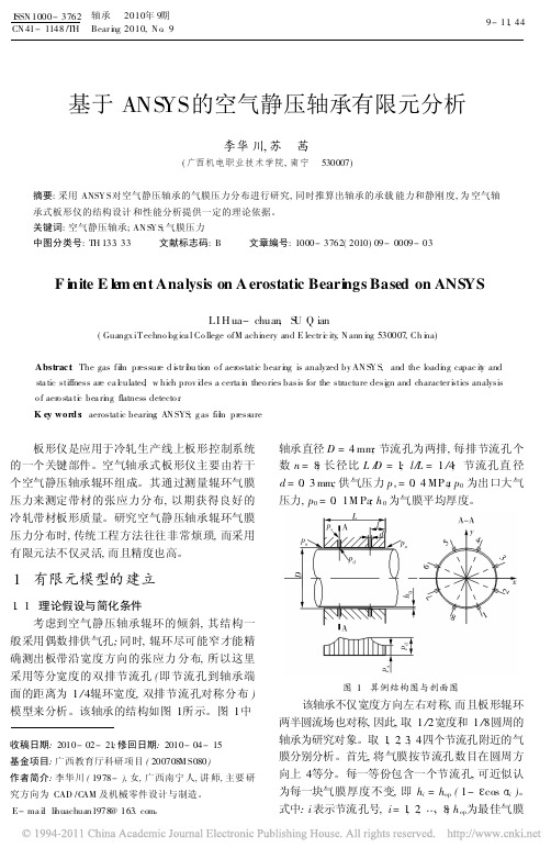
基于ANS YS 的空气静压轴承有限元分析李华川,苏 茜(广西机电职业技术学院,南宁 530007)摘要:采用ANSY S 对空气静压轴承的气膜压力分布进行研究,同时推算出轴承的承载能力和静刚度,为空气轴承式板形仪的结构设计和性能分析提供一定的理论依据。
关键词:空气静压轴承;AN S Y S ;气膜压力中图分类号:TH 133.33 文献标志码:B 文章编号:1000-3762(2010)09-0009-03F i nite E l e m ent Analysis on A erostatic Beari ngs Based on ANS YSLI H ua-chuan ,S U Q ian(Guangx iT echno l og ica l Co llege ofM achi nery and E lectr i c ity ,N ann i ng 530007,Ch i na)Abstrac t :The gas fil m pressure d i str i bu tion o f aerostatic bear i ng is analyzed by AN S Y S ,and the loadi ng capac it y and sta tic stiffness are ca l culated ,w hich prov i des a certa i n theo ries basis for the structure desi gn and character i stics analysis o f aero sta ti c bea ri ng flatness detecto r .K ey word s :aerostatic bearing ;AN SYS ;g as fil m press ure板形仪是应用于冷轧生产线上板形控制系统的一个关键部件。
空气轴承式板形仪主要由若干个空气静压轴承辊环组成。
ANSYS-轴承座 (3-D实体结构) 有限元分析

练习:轴承座 (3-D实体结构)有限元分析1.启动ANSYS(1)Utility Menu→File→Change Directory…改变工作目录(2) Utility Menu→File→Change Jobname…定义文件名(3) Utility Menu→File→Change Title…定义分析标题2.定义分析类型GUI:Main Menu→Preferences,在对话框中选择分析类型为Structural,程序分析方法为h-Method.3.定义单元类型:定义10-节点四面体实体结构单元(SOLID92)Main Menu: Preprocessor →Element Type→Add/Edit/Delete →Add,在弹出的对话框中左边选择Structural Solid ,右边框选择Tet 10 Node 92→OK4. 定义材料特性Main Menu:Preprocessor→Material Props→Material Models,Structural→Linear→Elastic→Isotropic。
输入弹性模量EX=3e7,泊松比PRXY=0.3,OK。
5.创建几何模型该模型是左右对称结构,只需创建对称部分。
整体坐标原点设在对称面与基座底面的后交点处。
(1)创建底座Main Menu: Preprocessor →Modeling →Create →Volumes →Block→By 2 Corners & Z 在弹出的对话框中分别输入:WPX,WPY,Width,Height,Depth(0,0,3,1,3)→OK。
即第一个角点在局部坐标系中的坐标值及体的宽度和高度(即第二个角点的坐标);Depth(3)为体的高度,沿WZ坐标轴。
取正值时图形沿局部坐标正向,取负值时图形沿局部坐标负方向绘出。
Utility Menu→PlotCtrls→ Pan,Zoom,Rotate→Iso绘正等侧视图。
基于ANSYS WORKBENCH轴承的模态分析
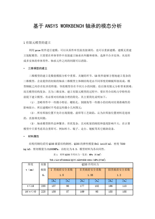
基于ANSYS WORKBENCH轴承的模态分析1有限元模型的建立利用proe软件进行建模,可以从原件库里面直接调用,也可以重新建模,建模无需建立装配模型,只需要在单体零件中直接建立轴承内外圈和球体,选择不合并实体,从而形成多实体的单体零件。
轴承元件之间的间隙可以消除。
•三维模型的建立三维模型的建立是数值模拟分析中重要、关键的环节。
UG软件能够方便地建立复杂的三维模型,企业提供的初始的轴承三维模型主体钢结构是由不同厚度的钢板焊接而成,模型钢板之间存在较多的焊缝,导致模型存在不同大小的间隙,给后继有限元分析带来困难,而且模型结构复杂,且为三维实体,建立有限元模型的过程中,要在符合结构力学特性的前提下建立模型,有必要对结构做合理的简化。
其主要简化说明如下:(1).忽略零件中一些微小特征。
螺栓孔、倒圆角等一些微小的结构对结果准确性的影响很小,所以建模时不考虑这些微小几何图元;(2).所有焊接位置不允许出现裂缝、虚焊等工艺缺陷,认为在焊接位置材料是连续的,直接填充间隙;(3).轴承模型附件品种繁多,形状复杂,且对机架的刚度和强度影响不大,在计算模型中只要考虑其自重即可,例如料斗、辊子、走台、链板等其它辅助设备。
•材料属性结构用钢均采用Q235碳素结构钢材,Q235的弹性模量E=2.1e11N/m2,密度7830kg/m3,剪切模量为81000MPa,泊松比为0.3,模型材料为各向同性。
表1 材料Q235许用应力一览表: MPa (N/mm2)Tab.1 List of Material Q235 Allowable stress: MPa (N/mm2)40<t≤100215 143 83 162 93 179 103•网格划分有限元网格数目过少,容易产生畸变,并影响计算精度;而数目过大,不仅对提高精度作用不大,反而大大增加了计算工作量[2]。
因此网格划分前对模型进行了体切割与粘接布尔用算,再采用自由划分方式,以满足计算精度与控制计算量的要求。
基于ANSYS的弹性轴承设计方法
义 N + 1 个橡胶层的 各层厚度可以不同
厚度
由大端到小端依次定
义 N 个钢片层的厚
度
大端球面锥角
小端球面锥角
大端最外球面的球半 小端球面半径由各
径
层厚度决定
rad _b ig_ho le rad_sm l_hole hh1 hh2
num _rubber_elem
大端中心孔半径 小端中心孔半径 大端块体延伸长度 小端块体延伸长度 每层橡胶厚度方向单 元划分数
覃海鹰 1 ,刘晓宁 2 ,王丁伟 1
(1. 中国直升机设计研究所 ,景德镇 , 333001; 2. 北京理工大学 ,北京 , 100081)
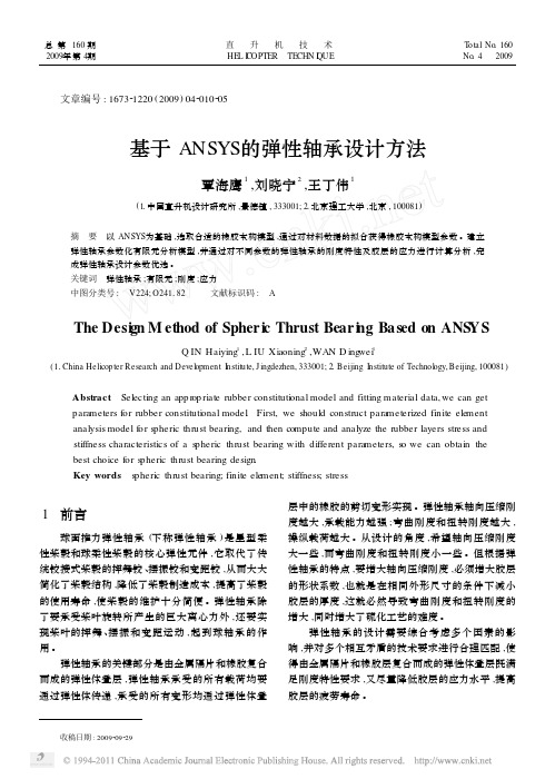
摘 要 以 ANSYS为基础 ,选取合适的橡胶本构模型 ,通过对材料数据的拟合获得橡胶本构模型参数 。建立 弹性轴承参数化有限元分析模型 ,并通过对不同参数的弹性轴承的刚度特性及胶层的应力进行计算分析 ,完 成弹性轴承设计参数优选 。 关键词 弹性轴承 ;有限元 ;刚度 ;应力 中图分类号 : V224; O241182 文献标识码 : A
图 3 轴向压缩载荷计算模型
4. 2. 3 弯曲刚度及胶层应力分析 弯曲刚度分析采用 1 /2对称模型 ,如图 4所示 。
固定大接头 ,在小接头上施加弯矩 ,可以得到在橡胶 线性变形范围内弯矩随小接头弯曲变形的关系曲 线 ,利用该曲线可以求出对应弯矩下的弯曲刚度 。
图 2 实验与拟和本构曲线
4. 2 弹性轴承刚度及胶层应力分析 4. 2. 1 边界条件
δ om ax
= 42°
金属橡胶叠层最小球 面半 径处 胶层 外径 角 :
δ om in
= 30°
图 1 工程应力 (σ) —工程应变 (ε)曲线
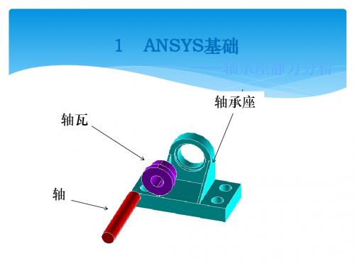
基于ANSYS的轴承座分析详解
20
(6)生成两个圆柱体 Main Menu: Preprocessor>Modeling>Create>Volumes>Cylinder> Solid Cylinder 在对话框中Radius输入1/Depth-0.2,Apply 再输入Radius输入0.8/Depth-2,点击OK。
21
(7)生成外围1/4圆柱体 Main Menu: Preprocessor>Modeling>Create>Volumes>Cylinder> Partial Cylinder+ 在对话框中输入Rad-2=1.3, Theta-2=90 Depth=-0.8 OK
40
41
8. 求解
Main Menu: Solution -> Solve>Current LS (1)浏览 status window 中出现的信息, 然后关闭此窗口。 (2)OK (开始求解). 关闭由于单元形状检Байду номын сангаас而出现的警告信息。 (3)求解结束后,关闭信息窗口。
9. 绘等效应力 (von Mises) 图.
(4)平移工作平面到关键点 Utility Menu>WorkPlane>Offset WP to >Keypoints+ 在刚刚生成的实体块的左上角拾取关键点,OK。
19
(5)旋转工作平面 Utility Menu>WorkPlane>Offset WP by Increments XY,YZ,ZX Angles输入0,90点击OK。
39
7. 在轴承孔的下半部分施加径向压力载荷,这 个载荷是由于受重载的轴承受到支撑作用而产生 的。
基于ANSYS的轴承-转子系统动力特性研究

式 中 : 、[ 】 和 【 分 别 表 示 系 统 整 体 的 质 量 【 C
矩 阵、 尼 矩 阵 和 刚度 矩 阵 ; £ )、{ t )、 阻 {( ) ( ) { ( )分别表示加速度 向量、 f ) 速度 向量 、 位移响应 向量 ; F £ )为动激励载荷向量。 {( ) 在进行模态分析时 , 通常可以通过研究无阻尼的 自由振动来 进行求解。在这种情况下 , ( ) 式 1 中的 【 】{ ( )和 { () c xt ) F )就不存 在 了。于是对 转子
() 4
自由振动时, 结构 的各个节点 的振幅 不全为
作者简介 : 何新荣(98 )男 , 18一 , 江西赣州人 , 在读硕士 , 研究方 向: 旋转机械故障诊断。
・
3 ・ 9
研 究 与 分析
・
机械研究与应用 ・
进行进一步的修正 , 即可得到需要 的有限元模型 ; 也 可 以在 A S S系统 中采用 直接 实体 建模 的方法 来完 NY 成。本文采用直接在 A S S N Y 建立模型。本模型 的难 点是如何建立弹簧 一 阻尼单元来模拟滑动 轴承与转 子之间的油膜 , 建立时主要通过 分块划分 网格 的形 式, 使转子和轴承上具体位置生成节点 , 然后连接转 子和轴承上 的节点来生成 弹簧 一 阻尼单元 。最后通 过改变弹簧一 阻尼单元的刚度和阻尼系数看转子系 统 的动力特性变化 , 验证了该模型的合理性。
D t [ I一∞ [ e( K MI)=0 () 5
2 模 态分析基本理论
对于一个实际连续的转子系统 , 经离散化后就变 成一个多 自由度系统 。根据弹性力学有限元理论 , 对 于一个 N 自由度线性弹性系统 , 其基本运动微分方
基于ANSYS的轴承座结构分析
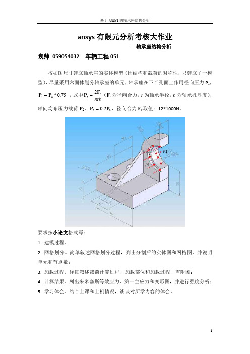
ansys 有限元分析考核大作业—轴承座结构分析袁帅 059054032 车辆工程051按如图尺寸建立轴承座的实体模型(因结构和载荷的对称性,只建立了一模型),尽量采用六面体划分轴承座的单元,轴承座在下半孔面上作用径向压力P 1,75.0*01P P = ,式中rbr πF P 20=(F r 为径向合力,r 为轴承半径,b 为轴承孔厚度),轴向均布压力载荷P 2,022.0P P =,径向合力F r 取值:12*1000N 。
要求按小论文格式写:1. 建模过程。
2. 网格划分。
简单叙述网格划分过程,列出分割后的实体图和网格图,并说明单元和节点数;3. 加载过程。
详细叙述载荷计算过程、加载部位和加载过程,需附图;4. 计算结果。
列出来米塞斯等效应力、第一主应力和变形图,并进行强度分析;5. 学习体会。
结合上课和上机情况,谈谈对所学内容的体会。
有限元分析考核大作业—基于ANSYS的轴承座结构分析山东矿业学院喜Confident /lfengxi一、有限元单元法与ANSYS简介有限元法是一种基于变分法(或变分里兹法)而发展起来的求解微分方程的数值计算方法,该方法以计算机为手段,采用分片近似、进而整体逼近的研究思想求解物理问题。
简而言之,其基本思想是里兹法加分片近似,可以归纳如下:首先,将物体或解域离散为有限个互不成叠仅通过节点相互连接的子域(即单元),原始边界条件也被转化为节点上的边界条件,此过程称为离散化。
其次,在单元内,选择简单近似函数来分片逼近未知的求解函数,即分片近似。
最后,基于与原问题数学模型(基本方程和边界条件)等效的变微分原理或加权残值法,建立有限元方程(即刚度方程),从而将微分方程转化为一组以变量或其导数的节点为未知量的代数方程组,进而借助矩阵和计算机求解代数方程组得到原问题的近似解。
ANSYS是在20世纪70年代由ANSYS公司开发的工程分析软件,开发初期是为了应用于电力工业,现在已经广泛应用于航空航天、汽车工业、生物医学、桥梁、建筑、电子产品、重型机械、微机电系统、运动器械等领域。
基于ANSYS的轴承座有限元分析

摘 要 :基 于 A YS软 件 对 某型搬 运 设备 的轴承 座进 行 强度 分析 。先通 过选 择 单元 类型 、划分 网格 、施加 边界 NS
条件 等 步骤 建 立轴 承座 的有 限元模 型 ,再对 某型搬 运设 备 的轴 承 座进 行 强度 和 变形分 析 ,找 出结构 最 易破 坏 的位 置 。 计 算结 果表 明该轴 承座 强度 符 合设 计要 求 ,轴 瓦孔 变形 远 小于轴 承 间 隙 ,能满 足最 小 油膜厚 度 的要 求 。 关 键 词 :轴承 座 ;有 限元 ; 最 小油膜 尺 寸
,
( . rn n eE gn eigColg , h iz u n 5 0 3 C ia 2 Me h nz t nIfnr a e , 1 O d a c n ie r l e S  ̄ah a g0 0 0 , hn ; . c a iai a t Ac d my n e o n y S 0a h a g0 0 8 , hn ; . b i iigC mmu iain&Co srcinL dC .S 0 ah a g0 0 1 h izu n 5 0 3 C ia 3 He e xn o Ha nc t o n t t t. , h iz u n 5 0 u o O 1 C ia 4 No 6 1 1 io L Z a  ̄ik u0 6 5 , hn ) hn ; . . 6 9 t f A, h n a o 7 1 1 C ia Un P
中 图 分 类 号 :T 2 7 P 7 文献 标 识码 :A
Fi t e e t n l sso a i a s d o SY S nieEl m n a y i fBe rng Se tBa e nAN A
LI .i n 一 W ANG n — i LIXi o f i Ze ta , Xi g we 。 a —e
ANSYS大作业_轴承座有限元分析

轴承座轴瓦 轴四个安装孔径向约束 (对称) 轴承座底部约束 (UY=0)沉孔上的推力 (3000 psi.) 向下作用力 (15000 psi.) 基于ANSYS 的轴承座有限元分析一、 问题描述在我们机械设计课程中曾经学习过轴系,主要是学习了轴的设计、受力分析以及轴承的设计等等。
但没有对轴承座的承受能力进行分析,所以我在这里主要是对一种简单的轴承座进行了有限元分析。
在查阅了相关资料之后,可将分析的轴承座示意如下图。
在实际当中,考虑到工艺的要求,图中相应的边缘处须设置有圆角、倒边等等。
但在有限元模型中忽略了这些要素。
二、 力学模型的分析与建立如下图所示在查阅了相关资料后可将上面描述的问题简化成上述模型,其中的载荷参考了网上的相关资料,在沉孔面上垂直于沉孔面上作用有3000psi.的推力载荷,在轴承孔的下半部分施加15000psi.的径向压力载荷,这个载荷是由于受重载的轴承受到支撑作用而产生的。
由于轴承座一般固定于机身上,所以可以在其底部施加法向位移约束,并且四个安装孔要受到螺栓的约束,所以可以在四个螺栓孔中施加径向对称约束(在ansys中体现为Symmetry B.C.)三、力学模型的有限元分析1.建立模型1)创建基座模型生成长方体Main Menu:Preprocessor->Modeling->Create->Volumes->Block->By Dimensions输入x1=0,x2=3,y1=0,y2=1,z1=0,z2=3平移并旋转工作平面Utility Menu>WorkPlane->Offset WP by IncrementsX,Y,Z Offsets 输入2.25,1.25,.75 点击ApplyXY,YZ,ZX Angles输入0,-90点击OK。
创建圆柱体Main Menu:Preprocessor->Modeling->Create->Volumes->Cylinder> Solid CylinderRadius输入0.75/2, Depth输入-1.5,点击OK。
滚动轴承ANSYS分析陈强
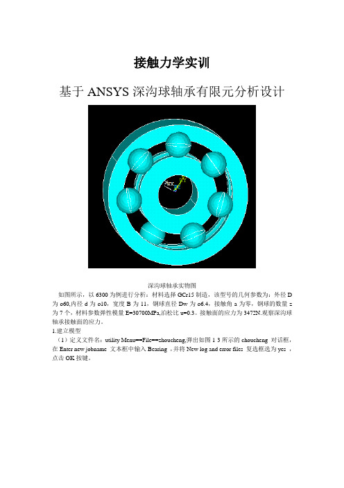
接触力学实训基于ANSYS深沟球轴承有限元分析设计深沟球轴承实物图如图所示,以6300为例进行分析:材料选择GCr15制造,该型号的几何参数为:外径D 为ø60,内径d为ø10,宽度B为11,钢球直径Dw为ø6.4,接触角a为零,钢球的数量z 为7个,材料参数弹性模量E=30700MPa,泊松比u=0.3。
接触面的应力为3472N.观察深沟球轴承接触面的应力。
1.建立模型(1)定义文件名:utility Menu==File==zhoucheng,弹出如图1-3所示的choucheng 对话框,在Enter new jobname 文本框中输入Bearing ,并将New log and error files 复选框选为yes ,点击OK按键。
图1-1 ANSYS开始界面图1-2 命名命令图1-3 命名对话框(2):定义单元类型:Main Menu==Preprocessor==Element Type==Add/Edit/Delete,弹出Element Types 对话框,如图1-4展现的,点击Add 按钮,出现1-5所示的Library of Element Types 对话框,点击选择Structural Solid 和Brick 8node 185 ,点击OK按键,然后点击Element Types 对话框出现的close按键,退出。
图1-4 Element Types 对话框图1-5 Library of Element Types 对话框(3):定义材料性质:Main Menu==Preprocessoe==Material Props==Material Models,出现如图1-7所示的 Define Material Model Behavior 对话框,在 Material Models Available 出现的选项中依次点击Structural==Linear==Elastic==Isotropic ,出现如图1-8所示 Linear Isotropic Propertities for Material 对话框,在EX 框中输入3E006,在PRXY 框中输入0.3,点击OK 按键。
基于ansys深沟球轴承有限元的分析

应力是时时变化的。当滚动体进入承载区后,所受 载荷即由0逐渐增加Q。。、Q。。,直到最大值Q一, 然后再逐渐减低到Q:。、Q。+直至0。滚动轴承工作 时,可以是外圈固定、内圈转动,也可以是内圈固 定、外圈转动。对于固定套圈,处于承载区内的各 接触点,按其所在位置的不同,将受到不同的载 荷。处于Q…作用线上的点将受到最大的接触载 荷,对于每一个具体的点,每当一个滚动体滚过 时,便承受一次载荷,其大小是不变的,也就是承 受稳定的脉动循环载荷的作用¨q o,如图1所示。
中图分类号:S
220
文献标志码:A
文章编号:0528-9017(2012)07—1053-03
滚动轴承是广泛应用的机械支承,一般由内 圈、外圈、滚动体和保持架组成。向心球轴承是最 常用的一类滚动轴承,适用范围宽,生产批量大。 它主要用于承受径向载荷,轴承摩擦系数小,适宜 于高速运转,且内部结构简单,易于达到较高的制 造精度。影响轴承寿命的主要因素是接触疲劳和磨 损,而这2种失效又与接触应力密不可分。 在实际工作中,轴承的负荷分布是一个静不定 问题,因此采用有限元分析方法会有比较好的效 果,为此,采用ansys有限元分析软件建立深沟球 轴承的有限元分析模型并尽量模拟其工作时的受载 情况进行加载求解,以得到比较有效的静力学接触 分析结果。 赫兹理论是赫兹1881年求得的关于接触应力
万方数据
1(154
澎江右尊矸学
取综合曲率半径为尺,则有百1=可1+瓦1。
若2球体材料相同,取肛=0.3,则有盯Ⅳ=
2’012年第7期
为泊松比。
…。
¨88浯。
当球面与平面接触时,取R:趋近于无穷大, R=R。,带人式中可得接触应力口“j。 但是当轴承的沟曲率半径系数工<0.6时,由 赫兹理论所计算出的结果与实际情况的误差开始变 大o¨,不能满足分析精度需要,此时,采用有限 元法计算会有好的效果。 3建模、约束条件、施加载荷和求解
ansys在轴承设计中的应用
ansys在轴承设计中的应用ANSYS是一种广泛应用于工程领域的有限元分析软件,它具有强大的计算能力和丰富的工具库,被广泛应用于轴承设计中。
轴承是一种常见的机械元件,用于支撑和定位旋转机械的轴。
在轴承设计中,需要考虑多个因素,如载荷、速度、温度、摩擦等。
通过使用ANSYS软件,可以对轴承进行全面的仿真和分析,以提高轴承的性能和寿命。
ANSYS可以帮助工程师模拟轴承的受力情况。
通过输入轴承的载荷、速度和几何参数,ANSYS可以计算出轴承内部的应力和变形情况。
这有助于工程师了解轴承在不同工况下的受力情况,从而优化轴承的设计。
ANSYS还可以模拟轴承的摩擦和磨损情况。
轴承在工作过程中会产生摩擦,摩擦会导致轴承磨损和能量损失。
通过使用ANSYS,工程师可以模拟轴承的摩擦行为,评估轴承的摩擦损失,并优化轴承的设计,减少能量损失和磨损。
ANSYS还可以模拟轴承的温度分布。
在高速和高负荷工况下,轴承会产生摩擦热,导致温度升高。
过高的温度会降低轴承的寿命和性能。
通过使用ANSYS,工程师可以模拟轴承的温度分布,评估轴承的热稳定性,并优化轴承的设计,提高轴承的散热性能。
ANSYS还可以模拟轴承的动态响应。
在高速旋转和不平衡载荷的情况下,轴承会产生振动和噪声。
通过使用ANSYS,工程师可以模拟轴承的动态响应,评估轴承的振动和噪声水平,并优化轴承的设计,减少振动和噪声。
ANSYS在轴承设计中的应用非常广泛。
通过使用ANSYS,工程师可以对轴承进行全面的仿真和分析,以提高轴承的性能和寿命。
在未来,随着ANSYS软件功能的不断更新和完善,轴承设计也将进一步发展和创新。
基于ANSYS的轴承座结构分析
基于ANSYS的轴承座结构分析一、有限元单元法与ANSYS简介有限元法是一种基于变分法(或变分里兹法)而发展起来的求解微分方程的数值计算方法,该方法以计算机为手段,采用分片近似、进而整体逼近的研究思想求解物理问题。
简而言之,其基本思想是里兹法加分片近似,可以归纳如下:首先,将物体或解域离散为有限个互不成叠仅通过节点相互连接的子域(即单元),原始边界条件也被转化为节点上的边界条件,此过程称为离散化。
其次,在单元内,选择简单近似函数来分片逼近未知的求解函数,即分片近似。
最后,基于与原问题数学模型(基本方程和边界条件)等效的变微分原理或加权残值法,建立有限元方程(即刚度方程),从而将微分方程转化为一组以变量或其导数的节点为未知量的代数方程组,进而借助矩阵和计算机求解代数方程组得到原问题的近似解。
ANSYS是在20世纪70年代由ANSYS公司开发的工程分析软件,开发初期是为了应用于电力工业,现在已经广泛应用于航空航天、汽车工业、生物医学、桥梁、建筑、电子产品、重型机械、微机电系统、运动器械等领域。
ANSYS软件主要包括三个部分:前处理模块,分析计算模块和后处理模块。
前处理模块提供了一个强大的实体建模及网格划分工具,用户可以方便地构造有限元模型;ANSYS 分析计算模块包括结构分析(可进行线性分析、非线性分析和高度非线性分析)、流体动力学分析、电磁场分析、声场分析、压电分析以及多物理场的耦合分析,可模拟多种物理介质的相互作用,具有灵敏度分析及优化分析能力;ANSYS后处理模块可将计算结果以彩色等值线显示、梯度显示、矢量显示、粒子流迹显示、立体切片显示、透明及半透明显示(可看到结构内部)等图形方式显示出来,也可将计算结果以图表、曲线形式显示或输出。
ANSYS 软件提供了100种以上的单元类型,用来模拟工程中的各种结构和材料。
二、实体模型的建立建立实体模型可以通过自上而下和自下而上两个途径:1、自上而下建模,首先要建立体(或面),对这些体或面按一定规则组合得到最终需要的形状。
(完整word版)基于ANSYS的轴承座有限元分析
轴承座的有限元分析摘要:在ANSYS环境下对轴承座进行建模,划分网格,生成有限元模型,并对其进行约束,加载,从而得到轴承座在工作载荷条件下的变形,应力,并对结果进行分析。
关键词:轴承座ANSYS 建模有限元0 引言轴承座在机械生产中很常见,在各类机器、机构中都有它存在的身影,由于轴承座本身结构并不是太复杂,所以本文并没有借助其他类型的三维软件建模,而是在ANSYS环境下建立的模型。
轴承座的受力主要是分布在轴承孔圆周上,还有轴承孔的下半部分的径向压力载荷。
本文将分析在这些载荷的作用下,轴承孔的变形,应力等,并显示强大的ANSYS的求解结果。
一、轴承座有限元模型的建立1.1、轴承座三维模型的创建由于轴承座为整体对称的结构,所以建模的总体思路为先建立模型的一半,然后在用ANSYS中的镜像命令创建另一半。
首先建立基座模型,输入基座长方体的两个对角顶点(0,1,0)和(3,1,3),建立一个长方体,然后平移工作平面,在基座上创建两个半径为0.325的圆柱,从长方体上减去两个圆柱便形成了两个圆柱孔,这样基座便建立好了。
然后再建立支撑部分,支撑分三部分建立,先建立一个长1。
5,宽0.75,高1。
75的长方体的块,在建立一个半径为1。
5的四分之一圆柱,最后建立轴承孔,值得注意的是建立轴承孔时需要建立两个半径分别为1和0。
85的圆柱为生成孔做准备,然后再依次剪掉两个圆柱,形成孔。
接着创建肋板不分,先通过三个点创建一个三角形的面,然后将该三角形拉成一个三棱柱,便建好了肋板。
然后将模型沿坐标平面镜像生成对称部分,最后粘贴所有体1。
2 、划分网格生成有限元模型首先定义材料属性,设置弹性模量EX为30e6,泊松比为0。
3。
然后用划分网格工具Mesh Tool将几何模型划分单元。
由于结构较复杂且为三维模型,故选择智能划分网格,即Smart Sizing,结果如图.二、施加边界与载荷先约束四个安装孔,依次选择四个安装孔的八个(每个圆柱面包括两个面)柱面,使其自由度为0,再在整个底座施加竖直方向上的位移约束,选择基座底面的所有外边界线,选择Uy作为约束自由度。
ANSYS在求解轴承接触问题中的应用
!&-
赫兹解和 )*+,+ 求解结果的比较 在表 " 中对赫兹解和几种尺寸单元网格下的
)*+,+ 解进行了比较。当单元尺寸大于接触圆 的半径时, )*+,+ 结果与赫兹解差距甚远。其计 算结果精度太差, 是不能采用的。因此在求解接 触问题时要保证有限元模型的单元尺寸不大于接 触椭圆的短半轴。 当有限元模型的网格边长尺寸与接触椭圆的
!%6 % 7" % % 7 " & !-’ % % 7 % & """ % & %54 7 - 3%’ & 3 接触
4’%! 7 % & %"! 7" % % & %47 " & !!% % % 7 % & !"3 % & !-3 7 - ’"6 & " 接触
4$5$ 7 % & %!$ ’ 7" % % & %37 " & -3! % % 7 % & "$! % & "3" 7 - $6$ & 6 接触
图! 钢球和半空间体接触的有限元 "#$ 模型
为单元边长为 % & %"! ’ (( 时, )*+,+ 求解的 !" 剖面内接触区及附近外表面节点的解。
表"
单元尺寸 / (( %&" % & %’ % & %!’ % & %"! ’
因此可提取节点的 面的节点上施加了 " 向的力, 载荷 !& , 如果 !& . %, 则节点处于接触状态, 否则 为非接触状态。
ANSYS轴承单元

ANSYS轴承单元!COMBI214 Element DescriptionCOMBI214 has longitudinal as well as cross-coupling capability in 2-D applications. It is a tension-compression element with up to two degrees of freedom at each node: translations in any two nodal directions (x, y, or z). COMBI214 has two nodes plus one optional orientation node. No bending or torsion is considered.The spring-damper element has no mass. Masses can be added by using the appropriate mass element (MASS21). The spring or the damping capability may be removed from the element.A longitudinal spring/damper with torsion capabilities is available via the COMBIN14 element. A general spring or damper is also available in the stiffness, damping or mass matrix element MATRIX27. Another spring-damper element having its direction of action determined by the nodal coordinate directions is COMBIN40.For more information about this element, see COMBI214 - 2-D Spring-Damper Bearing in the ANSYS, Inc. Theory Reference.Figure 214.1 COMBI214 GeometryCOMBI214 Element DescriptionCOMBI214 has longitudinal as well as cross-couplingcapability in 2-D applications. It is a tension-compression element with up to two degrees of freedom at each node: translations in any two nodal directions (x, y, or z). COMBI214 has two nodes plus one optional orientation node. No bending or torsion is considered.The spring-damper element has no mass. Masses can be added by using the appropriate mass element (MASS21). The spring or the damping capability may be removed from the element.A longitudinal spring/damper with torsion capabilities is available via the COMBIN14 element. A general spring or damper is also available in the stiffness, damping or mass matrix element MATRIX27. Another spring-damper element having its direction of action determined by the nodal coordinate directions is COMBIN40.For more information about this element, see COMBI214 - 2-D Spring-Damper Bearing in the ANSYS, Inc. Theory Reference.COMBI214 Input DataThe geometry, node locations, and coordinate system for this element are shown in Figure 214.1: "COMBI214 Geometry". The element is defined by two nodes. It has stiffness characteristics K11, K22, K12 and K21 and damping characteristics C11, C22, C12 and C21. The stiffness coefficients should have units of Force/Length, and the damping coefficient units are Force*Time/Length. (The damping capability is not used for static or undamped modal analyses.)The third node is for orientation and applies to nonlinear analyses only.For stiffness and damping real constants, either numerical values or tabular array inputs can be specified. If specifying tabular inputs, enclose the table name within “%” characters (%tabname%). These real constants can vary with the amplitude of the rotational velocity vector (defined via the OMEGA or CMOMEGA command). Use the *DIM command and the primary variable OMEGS to dimension the table and identify the variable. Because the amplitude of the rotational velocity vector is an absolute value, only positive values of OMEGS in the table parameter are valid. For more information about using tabular inputs, see Array Parameters in the ANSYS APDL Programmer's Guide, Applying Loads Using TABLE Type Array Parameters in the ANSYS Basic Analysis Guide, and Performing a Thermal Analysis Using Tabular Boundary Conditions in the ANSYS Thermal Analysis Guide.KEYOPT(2) = 0 through 2 options define the element plane. The element operates in the nodal coordinate system.The KEYOPT(3) = 0 and 1 options specify whether or not the element is symmetric. When symmetric, cross-coupling terms in stiffness and damping coefficients are equal (that is, K12 = K21 and C12 = C21).A summary of the element input is given in "COMBI214 Input Summary". A general description of element input is given inElement Input.COMBI214 Input SummaryNodesI, J, K (The K orientation node is optional and for nonlinear analyses only.)Degrees of FreedomUX, UY (KEYOPT (2) = 0)UY, UZ (KEYOPT (2) = 1)UX, UZ (KEYOPT (2) = 2)Real ConstantsK11, K22, K12, K21 , C11, C22, C12, C21Kij - (i=1,2 j=1,2) Stiffness coefficientsCij - (i=1,2 j=1,2) Damping coefficientsNoteReal constants may be defined as table parameters as a function of omega (using primary variable OMEGS).Material PropertiesNoneSurface LoadsNoneBody LoadsNoneSpecial FeaturesStress stiffeningLarge deflectionsBirth and deathKEYOPT(2)Degrees of freedom selection:0 --Element lies in a plane parallel to the XY plane. The degrees of freedom are UX and UY. This value option is the default.1 --Element lies in a plane parallel to the YZ plane. The degrees of freedom are UY and UZ.2 --Element lies in a plane parallel to the XZ plane. The degrees of freedom are UX and UZ.KEYOPT(3)Symmetry:0 --Element is symmetric: K12 = K21 and C12 = C21. This option is the default.1 --Element is not symmetric.COMBI214 Output DataThe solution output associated with the element is in two forms:Nodal displacements included in the overall nodal solutionAdditional element output as shown in Table 214.1: "COMBI214 Element Output Definitions".The Element Output Definitions table uses the following notation:(1) and (2) indicate the first and second axis of the element plane defined by KEYOPT(2). For example, if KEYOPT(2) equals 0, then (1) is the X axis and (2) is the Y axis.A colon (:) in the Name column indicates the item can be accessed by the Component Name method [ETABLE, ESOL]. The O column indicates the availability of the items in the file Jobname.OUT. The R column indicates the availability of the items in the results file.In either the O or R columns, Y indicates that the item is always available, a number refers to a table footnote that describes when the item is conditionally available, and a - indicates that the item is not available.Table 214.1 COMBI214 Element Output DefinitionsName Definition O REL Element Number Y YNODES Nodes - I, J Y YXC, YC, ZC Location where results are reported Y 1FORC1 Spring force along (1) Y YFORC2 Spring force along (2) Y YSTRETCH1 Stretch of spring along (1) Y YSTRETCH2 Stretch of spring along (2) Y YVELOCITY1 Velocity along (1) - YVELOCITY2 Velocity along (2) - YDAMPING FORCE1 Damping force along (1) -- Zero unless this is a transient analysis (ANTYPE,TRANS) and damping is present Y YDAMPING FORCE2 Damping force along (2) -- Zero unless this is a transient analysis (ANTYPE,TRANS) and damping is present Y YAvailable only at centroid as a *GET item.Table 214.2: "COMBI214 Item and Sequence Numbers" lists output available via the ETABLE command using the Sequence Number method. See Chapter 5: "The General Postprocessor (POST1)" in the ANSYS Basic Analysis Guide and The Item and Sequence Number Table in this document for more information. The following notation is used in Table 214.2: "COMBI214 Item and Sequence Numbers":NameOutput quantity as defined in Table 214.1: "COMBI214 Element Output Definitions"ItemPredetermined Item label for the ETABLE commandESequence number for single-valued or constant element dataOutput data for COMBI214 consists of the following:Table 214.2 COMBI214 Item and Sequence NumbersOutput Quantity Name ETABLE and ESOL Command Input Item EFORC1 SMISC 1FORC2 SMISC 2STRETCH1 NMISC 1STRETCH2 NMISC 2VELOCITY1 NMISC 3VELOCITY2 NMISC 4DAMPING FORCE1 NMISC 5DAMPING FORCE2 NMISC 6COMBI214 Assumptions and RestrictionsNodes must lie in the plane defined by KEYOPT(2).The following applies to a nonlinear analysis:-- The orientation node K is required.-- The length of the spring-damper element must not be zero (that is, nodes I, J and K should not be coincident because the node locations determine the spring orientation).Line (IJ) must be parallel to (1). Line (JK) must be parallel to (2).The element allows only a uniform stress in the springs.The following applies when KEYOPT(3) = 0 (symmetric):-- If K12 is non-zero and K21 is zero, then K21 is set to K12.-- If C12 is non-zero and C21 is zero, then C21 is set to C12.The spring or the damping capability may be deleted from the element by setting all Kij (i=1,2 j=1,2) or all Cij (i=1,2 j=1,2) equal to zero, respectively.The degrees of freedom are specified in the nodal coordinate system and are the same for both nodes. (For more information, see Elements that Operate in the Nodal Coordinate System.) If the nodal coordinate systems are rotated relative to each other, the same degree of freedom may be in different directions (thereby giving possibly unexpected results).No moment effects are included; that is, if the nodes areoffset from the lines of action, moment equilibrium may not be satisfied.The element is defined such that a positive displacement of node J relative to node I tends to stretch the spring. If, for a given set of conditions, nodes I and J are interchanged, a positive displacement of node J relative to node I tends to compress the spring.COMBI214 Product RestrictionsWhen used in the product(s) listed below, the stated product-specific restrictions apply to this element in addition to the general assumptions and restrictions given in the previous section.ANSYS Professional. Structural Analysis:No damping capability; Cij (i=1,2 j=1,2) are not allowed.Only stress stiffening and large deflections are allowed.。
- 1、下载文档前请自行甄别文档内容的完整性,平台不提供额外的编辑、内容补充、找答案等附加服务。
- 2、"仅部分预览"的文档,不可在线预览部分如存在完整性等问题,可反馈申请退款(可完整预览的文档不适用该条件!)。
- 3、如文档侵犯您的权益,请联系客服反馈,我们会尽快为您处理(人工客服工作时间:9:00-18:30)。
A longitudinal spring/damper with torsion capabilities is available via the COMBIN14 element. A general spring or damper is also available in the stiffness, damping or mass matrix element MATRIX27. Another spring-damper element having its direction of action determined by the nodal coordinate directions is COMBIN40.
The spring-damper element has no mass. Masses can be added by using the appropriate mass element (MASS21). The spring or the damping capability may be removed from the element.
None
Body Loads
None
Special Features
Stress stiffening
Large deflections
Birth and death
KEYOPT(2)
Degrees of freedom selection:
0 --
Element lies in a plane parallel to the XY plane. The degrees of freedom are UX and UY. This value option is the default.
Note
Real constants may be defined as table parameters as a function of omega (using primary variable OMEGS).
Material Properties
None
Surface Loads
Nodes
I, J, K (The K orientation node is optional and for nonlinear analyses only.)
Degrees of Freedom
UX, UY (KEYOPT (2) = 0) UY, UBiblioteka (KEYOPT (2) = 1)
A summary of the element input is given in "COMBI214 Input Summary". A general description of element input is given in Element Input.
COMBI214 Input Summary
For more information about this element, see COMBI214 - 2-D Spring-Damper Bearing in the ANSYS, Inc. Theory Reference.
Figure 214.1 COMBI214 Geometry
!
COMBI214 Element Description
COMBI214 has longitudinal as well as cross-coupling capability in 2-D applications. It is a tension-compression element with up to two degrees of freedom at each node: translations in any two nodal directions (x, y, or z). COMBI214 has two nodes plus one optional orientation node. No bending or torsion is considered.
KEYOPT(2) = 0 through 2 options define the element plane. The element operates in the nodal coordinate system.
The KEYOPT(3) = 0 and 1 options specify whether or not the element is symmetric. When symmetric, cross-coupling terms in stiffness and damping coefficients are equal (that is, K12 = K21 and C12 = C21).
1 --
Element lies in a plane parallel to the YZ plane. The degrees of freedom are UY and UZ.
2 --
Element lies in a plane parallel to the XZ plane. The degrees of freedom are UX and UZ.
A longitudinal spring/damper with torsion capabilities is available via the COMBIN14 element. A general spring or damper is also available in the stiffness, damping or mass matrix element MATRIX27. Another spring-damper element having its direction of action determined by the nodal coordinate directions is COMBIN40.
The spring-damper element has no mass. Masses can be added by using the appropriate mass element (MASS21). The spring or the damping capability may be removed from the element.
The solution output associated with the element is in two forms:
For more information about this element, see COMBI214 - 2-D Spring-Damper Bearing in the ANSYS, Inc. Theory Reference.
COMBI214 Input Data
The geometry, node locations, and coordinate system for this element are shown in Figure 214.1: "COMBI214 Geometry". The element is defined by two nodes. It has stiffness characteristics K11, K22, K12 and K21 and damping characteristics C11, C22, C12 and C21. The stiffness coefficients should have units of Force/Length, and the damping coefficient units are Force*Time/Length. (The damping capability is not used for static or undamped modal analyses.)
KEYOPT(3)
Symmetry:
0 --
Element is symmetric: K12 = K21 and C12 = C21. This option is the default.
1 --
Element is not symmetric.
COMBI214 Output Data
The third node is for orientation and applies to nonlinear analyses only.
For stiffness and damping real constants, either numerical values or tabular array inputs can be specified. If specifying tabular inputs, enclose the table name within “%” characters (%tabname%). These real constants can vary with the amplitude of the rotational velocity vector (defined via the OMEGA or CMOMEGA command). Use the *DIM command and the primary variable OMEGS to dimension the table and identify the variable. Because the amplitude of the rotational velocity vector is an absolute value, only positive values of OMEGS in the table parameter are valid. For more information about using tabular inputs, see Array Parameters in the ANSYS APDL Programmer's Guide, Applying Loads Using TABLE Type Array Parameters in the ANSYS Basic Analysis Guide, and Performing a Thermal Analysis Using Tabular Boundary Conditions in the ANSYS Thermal Analysis Guide.
